EP2357363A1 - Operational management device for a positive displacement pump, pump system and method of operating such - Google Patents
Operational management device for a positive displacement pump, pump system and method of operating such Download PDFInfo
- Publication number
- EP2357363A1 EP2357363A1 EP10001449A EP10001449A EP2357363A1 EP 2357363 A1 EP2357363 A1 EP 2357363A1 EP 10001449 A EP10001449 A EP 10001449A EP 10001449 A EP10001449 A EP 10001449A EP 2357363 A1 EP2357363 A1 EP 2357363A1
- Authority
- EP
- European Patent Office
- Prior art keywords
- pump
- operating
- operating parameter
- mode
- pressure
- Prior art date
- Legal status (The legal status is an assumption and is not a legal conclusion. Google has not performed a legal analysis and makes no representation as to the accuracy of the status listed.)
- Granted
Links
Images

Classifications
-
- F—MECHANICAL ENGINEERING; LIGHTING; HEATING; WEAPONS; BLASTING
- F04—POSITIVE - DISPLACEMENT MACHINES FOR LIQUIDS; PUMPS FOR LIQUIDS OR ELASTIC FLUIDS
- F04C—ROTARY-PISTON, OR OSCILLATING-PISTON, POSITIVE-DISPLACEMENT MACHINES FOR LIQUIDS; ROTARY-PISTON, OR OSCILLATING-PISTON, POSITIVE-DISPLACEMENT PUMPS
- F04C2/00—Rotary-piston machines or pumps
- F04C2/08—Rotary-piston machines or pumps of intermeshing-engagement type, i.e. with engagement of co-operating members similar to that of toothed gearing
- F04C2/12—Rotary-piston machines or pumps of intermeshing-engagement type, i.e. with engagement of co-operating members similar to that of toothed gearing of other than internal-axis type
- F04C2/14—Rotary-piston machines or pumps of intermeshing-engagement type, i.e. with engagement of co-operating members similar to that of toothed gearing of other than internal-axis type with toothed rotary pistons
- F04C2/16—Rotary-piston machines or pumps of intermeshing-engagement type, i.e. with engagement of co-operating members similar to that of toothed gearing of other than internal-axis type with toothed rotary pistons with helical teeth, e.g. chevron-shaped, screw type
-
- F—MECHANICAL ENGINEERING; LIGHTING; HEATING; WEAPONS; BLASTING
- F04—POSITIVE - DISPLACEMENT MACHINES FOR LIQUIDS; PUMPS FOR LIQUIDS OR ELASTIC FLUIDS
- F04B—POSITIVE-DISPLACEMENT MACHINES FOR LIQUIDS; PUMPS
- F04B49/00—Control, e.g. of pump delivery, or pump pressure of, or safety measures for, machines, pumps, or pumping installations, not otherwise provided for, or of interest apart from, groups F04B1/00 - F04B47/00
- F04B49/02—Stopping, starting, unloading or idling control
- F04B49/022—Stopping, starting, unloading or idling control by means of pressure
-
- F—MECHANICAL ENGINEERING; LIGHTING; HEATING; WEAPONS; BLASTING
- F04—POSITIVE - DISPLACEMENT MACHINES FOR LIQUIDS; PUMPS FOR LIQUIDS OR ELASTIC FLUIDS
- F04B—POSITIVE-DISPLACEMENT MACHINES FOR LIQUIDS; PUMPS
- F04B49/00—Control, e.g. of pump delivery, or pump pressure of, or safety measures for, machines, pumps, or pumping installations, not otherwise provided for, or of interest apart from, groups F04B1/00 - F04B47/00
- F04B49/06—Control using electricity
- F04B49/065—Control using electricity and making use of computers
-
- F—MECHANICAL ENGINEERING; LIGHTING; HEATING; WEAPONS; BLASTING
- F04—POSITIVE - DISPLACEMENT MACHINES FOR LIQUIDS; PUMPS FOR LIQUIDS OR ELASTIC FLUIDS
- F04B—POSITIVE-DISPLACEMENT MACHINES FOR LIQUIDS; PUMPS
- F04B7/00—Piston machines or pumps characterised by having positively-driven valving
- F04B7/02—Piston machines or pumps characterised by having positively-driven valving the valving being fluid-actuated
-
- F—MECHANICAL ENGINEERING; LIGHTING; HEATING; WEAPONS; BLASTING
- F04—POSITIVE - DISPLACEMENT MACHINES FOR LIQUIDS; PUMPS FOR LIQUIDS OR ELASTIC FLUIDS
- F04C—ROTARY-PISTON, OR OSCILLATING-PISTON, POSITIVE-DISPLACEMENT MACHINES FOR LIQUIDS; ROTARY-PISTON, OR OSCILLATING-PISTON, POSITIVE-DISPLACEMENT PUMPS
- F04C14/00—Control of, monitoring of, or safety arrangements for, machines, pumps or pumping installations
- F04C14/06—Control of, monitoring of, or safety arrangements for, machines, pumps or pumping installations specially adapted for stopping, starting, idling or no-load operation
-
- F—MECHANICAL ENGINEERING; LIGHTING; HEATING; WEAPONS; BLASTING
- F04—POSITIVE - DISPLACEMENT MACHINES FOR LIQUIDS; PUMPS FOR LIQUIDS OR ELASTIC FLUIDS
- F04C—ROTARY-PISTON, OR OSCILLATING-PISTON, POSITIVE-DISPLACEMENT MACHINES FOR LIQUIDS; ROTARY-PISTON, OR OSCILLATING-PISTON, POSITIVE-DISPLACEMENT PUMPS
- F04C14/00—Control of, monitoring of, or safety arrangements for, machines, pumps or pumping installations
- F04C14/08—Control of, monitoring of, or safety arrangements for, machines, pumps or pumping installations characterised by varying the rotational speed
-
- F—MECHANICAL ENGINEERING; LIGHTING; HEATING; WEAPONS; BLASTING
- F04—POSITIVE - DISPLACEMENT MACHINES FOR LIQUIDS; PUMPS FOR LIQUIDS OR ELASTIC FLUIDS
- F04C—ROTARY-PISTON, OR OSCILLATING-PISTON, POSITIVE-DISPLACEMENT MACHINES FOR LIQUIDS; ROTARY-PISTON, OR OSCILLATING-PISTON, POSITIVE-DISPLACEMENT PUMPS
- F04C2240/00—Components
- F04C2240/80—Other components
- F04C2240/81—Sensor, e.g. electronic sensor for control or monitoring
-
- F—MECHANICAL ENGINEERING; LIGHTING; HEATING; WEAPONS; BLASTING
- F04—POSITIVE - DISPLACEMENT MACHINES FOR LIQUIDS; PUMPS FOR LIQUIDS OR ELASTIC FLUIDS
- F04C—ROTARY-PISTON, OR OSCILLATING-PISTON, POSITIVE-DISPLACEMENT MACHINES FOR LIQUIDS; ROTARY-PISTON, OR OSCILLATING-PISTON, POSITIVE-DISPLACEMENT PUMPS
- F04C2270/00—Control; Monitoring or safety arrangements
- F04C2270/18—Pressure
Definitions
- the present invention relates to an operation control apparatus according to the preamble of the main claim, further to a pump system and a method for operating a pump system.
- a (three-spindle) screw pump has proven and enforced as a positive displacement pump, due to its low-pulsation and uniform conveying characteristics, combined with high wear resistance.
- screw pumps in a system with associated equipment (eg, the machine tool) require a pressure control valve to maintain a (predetermined) pump pressure constant.
- the pumps are operated at a constant speed and provide an approximately constant flow rate due to their displacement characteristics.
- One each in a machine tool used tool requires at the predetermined pressure a fluid flow rate, which is usually below the amount provided by the pump; Accordingly, the excess flow rate (differential flow rate) is derived via the pressure control valve, whereby the efficiency of the system compared to the (in principle possible) high efficiency of the positive displacement pump is reduced, since the necessary for the pressure build-up in the differential flow pump capacity is not used.
- a shut-off valve is installed in the supply line to the machine tool, or the pump is switched off;
- the pump will continue to operate (with the shut-off valve closed) at full power via the pressure regulator, with consequent detrimental effects on efficiency.
- a controllable pressure control valve is often used, which can be depressurized in the working cycles.
- valves used for pressure control are disadvantageous in systems for coolant supply of machine tools, the switching of the valves leads to pressure pulsations, which load the system heavily, possibly even causing mechanical damage.
- the variation of the rotational speed of the pump motor by means of a frequency converter is known. It is intended to return the pressure in the system after the pump via a pressure sensor as a control variable to the frequency converter and impart the pump motor speed as a control variable by means of a PI control (via the inverter) on the pump motor.
- the object of the present invention is therefore to provide an operating control device for a positive displacement pump having a pump motor, which after activating the target variables, such as a target pressure and / or a target speed in the shortest possible time and without over or undershoot effects in Control process achieved.
- target variables such as a target pressure and / or a target speed in the shortest possible time and without over or undershoot effects in Control process achieved.
- high equipment costs, in particular additional effort through shut-off and / or pressure control valves to avoid.
- the drive means according to the invention are assigned operating mode means so that they can specify a plurality of operating modes (outside a switch-off state).
- the inventive approach allows in the first drive mode and in response to the detected operating parameter change in the predetermined time interval, adaptive and dependent on the with minimal rise time to increase the pump pressure (operating pressure, as a typical implementation of the operating parameter) and then according to the invention upon reaching or exceeding the first operating parameter threshold (ie, about a pressure or Drehiereschwellwerts) switch to the second control mode, which, to approximate the operating parameter target value (ie, about the desired pressure or a target speed) a less steep and thus overshooting allows avoidance of operation; Subsequently, the setpoint value would then also be adjusted in otherwise known manner in stationary operation in this second operating mode.
- the first operating parameter threshold value is defined as a predetermined fraction of the operating parameter target value or is calculated according to the invention, whereby this fraction according to preferred embodiments of the invention in the range between 90% and 98% of the desired value, in particular in the range between 94% and 96% of the target value, moves.
- this fraction according to preferred embodiments of the invention in the range between 90% and 98% of the desired value, in particular in the range between 94% and 96% of the target value, moves.
- the operating mode means additionally use a second operating parameter threshold value (that is to say pressure threshold value) which lies below the first operating parameter threshold value and triggers the detection of the parameter change (relative to the time unit) according to the invention;
- a second operating parameter threshold value that is to say pressure threshold value
- This inventive aspect is based on the inventive finding that favorable detection conditions do not already exist immediately after activating or switching on, but rather only after reaching a threshold (determined by the second operating parameter threshold), for example a pressure threshold, which according to preferred developments the invention in the range between about 15% and 25%, preferably 20%, for example, based on the operating parameter target value.
- control behavior in the first and in the second operating mode by a control behavior, such as a PI control behavior to map, while providing a demarcation between the Anêtmodi, such as by changing the control gain factor.
- a control behavior such as a PI control behavior to map
- the operating pressure pump pressure
- Both the first threshold value and the second threshold value are then present with this setpoint pressure as the pressure threshold value.
- the state sensor means are realized by means of a pressure sensor which detects and provides this operating pressure (preferably continuously).
- the operating pressure as an operating parameter not directly by means of a sensor, but to determine it from other system and pump parameters (in otherwise known manner) which are present within the pump system, in particular using the (Pump) motor voltage, the motor current, the motor speed, a motor rotational acceleration or other (about constant) pump parameters of a respective positive displacement pump used which are suitable for operating pressure determination and charged in an otherwise known manner for pressure determination.
- the operating parameter setpoint and the at least one threshold need not necessarily be the same size (e.g., pressure).
- the operation control device is used in a pump system, which assigns the operation control device, a positive displacement pump and an impinged by the positive displacement pump with fluid unit; preferred and advantageous in the context of the invention is the positive displacement pump (more preferably dreispindelige) screw pump, the aggregate a machine tool, which further preferably with an operating pressure above 20bar, even more preferably above 40bar, and still more preferably above 60bar with cooling lubricant is acted upon by the positive displacement pump. It is particularly favorable and advantageous to operate the screw pump in the manner of a universal pump at high speeds, since in this way comparatively small and inexpensive pumps can be used. Accordingly, it is provided within the scope of preferred developments of the invention to provide positive displacement pumps, in particular screw pumps, which are operated at operating speeds above 3000 / min., More preferably above 4000 / min., Within the pump system.
- the operating parameter target value such as the target pressure to reach in less than 500ms and thus represents a significant advance over procedures according to the prior art.
- the present invention can be dispensed with valves for pressure control of the pump, the present invention not only advantageous to avoid additional mechanical and aggregate effort, also exists about the above-described, adverse pulsation by the valve switching operations not even.
- the present invention makes it possible to solve, in a surprisingly simple and elegant manner, the problem of dynamic performance arising from the prior art, ie, quickly achieving an operating parameter setpoint without overshoot, without requiring additional mechanical effort by valves or the like . becomes necessary.
- the prerequisite for a high degree of flexibility and adaptability to different operating conditions such as different tools to be operated in a machine tool, each with different pressure conditions, created without complex adjustment, (pre-) Configuring or the like. Measures necessary
- significant increases in efficiency can also be achieved in furnishing and retrofitting processes.
- the present invention is particularly suitable in the described manner for the application of high-pressure pumps for fluid supply for machine tools in industrial environments, but is not limited to this application. Rather, the present invention provides the advantages described in all technical applications, which need adaptive, flexible control behavior of pumps, especially in the high pressure area.
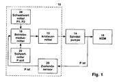
- the Fig. 1 illustrates in the form of a schematic block diagram the operation control device according to a preferred embodiment of the invention in the context of a pump system. More specifically, the block diagram illustrates the Fig. 1 characterized by the dashed border line 10, an operation control device with drive means 12, typically realized as otherwise known frequency converter, for speed adjustment and control of a downstream screw pump 14, which in the context of in the Fig. 1 shown system for conveying cooling fluid with a schematically shown machine tool 16 (typical example drilling or milling machine with exchangeable tool inserts and correspondingly variable flow rate requirement for a respective tool) cooperates.
- a schematically shown machine tool 16 typically drilling or milling machine with exchangeable tool inserts and correspondingly variable flow rate requirement for a respective tool
- the drive means 12 are preceded by operating mode means 18 in the form of a control unit (typically realized from hardware or software components) which in the context of the invention in its control behavior with respect to the drive means 12 both calculated or predetermined threshold values 24 of an operating parameter (in the present Fall the pump pressure P) flow, as well as a respective aggregate-specific setpoint 22 of the operating parameter (here: set pressure P soll) into account.
- a control unit typically realized from hardware or software components
- these influencing factors namely at least one threshold value and the desired value P set, by means of functional units 22, 24 suitably provided (or as explained below, calculated).
- a state sensor unit 20 in the exemplary embodiment shown a pressure sensor, on the output side of the spindle pump 14 detects an actual pressure "P ist" and sends it to the operating mode means 18 for consideration in the context of the further control.
- a screw spindle pump of the type EMTEC 20 R38 of the Applicant Allweiler AG, Radolfzell, a power of 7.5 kW with a single-spindle machine tool 16 cooperates, which is designed as a drill and a total of three different drilling tools is operated.
- Each of these three drilling tools requires a different flow rate of a coolant / lubricant fluid to be delivered by the pump 14, it being assumed that this flow rate is between 5 l / min. and 35l / min. lies.
- An assumed operating pressure on the pump output or aggregate input side is assumed to be 80 bar.
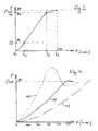
- the Fig. 2 schematically shows an idle state in step S10 before activating the arrangement.
- manual or automated control then follows in step S12, the commissioning Go.
- the present invention allows by suitable control or setting by the operating mode means 18 operating the pump motor in several clearly separated or distinct operating phases.
- a driving of the spindle pump by means of the frequency converter 12 with maximum electrical drive power is a driving of the spindle pump by means of the frequency converter 12 with maximum electrical drive power.
- this means realizing a lower threshold, in the exemplary embodiment at the 80% threshold (based on 80 bar P soll, ie P2 16 bar). Accordingly, the branching leads into Fig. 3 to the operating state of step S14 "Start", corresponding to an initial start-up mode, here at full electric power.
- the mode-of-operation means applies a different drive mode to the pump motor and the upstream inverter, respectively.
- a parameterization of a control operation in the second operating phase between times t 1 and t 2 in is thus carried out in step S16 Fig.
- a PI control operation is carried out here, wherein, after the time t 1 , by the operating mode means 18 first a pressure difference per time interval as a slope of the pressure curve ( Fig. 2 ) is determined and dependent on this slope then the system determines and specifies a gain value and an integration time for the PI control behavior in the time period t 1 and t 2 , which then in step S18, the system continues to operate with this parameterization and described by a PI control function becomes. As well as by the feedback of the Fig.
- a continuous parameterization takes place, ie repeated measurement of a current slope of the pressure curve and then adjustment of P and I values of the control.
- step S20 the system performs the so-called end control operation in step S20, namely a control operation, which typically compared to a control operation in the upstream operating phase has a reduced gain and / or extended integration time for the PI parameterization, in other words, from the upper threshold, a significantly flatter rise behavior towards the target value P soll shows.
- a control operation typically compared to a control operation in the upstream operating phase has a reduced gain and / or extended integration time for the PI parameterization, in other words, from the upper threshold, a significantly flatter rise behavior towards the target value P soll shows.
- P soll 80 bar
- the flowchart shows the Fig. 3 initiating an alarm routine (steps S22 and S24, respectively) if a predetermined alarm condition is detected in step E3; this can be a predetermined pressure behavior, but also switch off on other input variables (eg exceeding a critical temperature).
- the shows Fig. 4 the performance of a presumed as known operation control device with the same pump configuration, which is realized for example in the form of a PI controller, for the various tools and the associated different system loads. While, for example, for the first boring tool according to curve 40, a small required flow rate (5 l / min) leads to a significant overshooting of the system, a high flow rate requirement of a large tool according to curve 42 (flow rate 35 l / min) causes a very long entry time and exceeds that needed 500msec limit significantly.
- the present invention is not limited to the provision of two threshold values P2, P1 (namely, as shown in the embodiment, at 20% and 95% of the desired value), but it is within the scope of the invention possible to deviate one or both of these thresholds
- the invention also includes placing or selecting only one threshold value (preferably the upper threshold value P1) or any desired number of threshold values (possibly described by a continuous functional relationship) and the adaptively parameterized operation as described above up to this upper limit Threshold value according to a single or repeated slope measurement on the pressure curve suitable to adjust or adjust.
- an upper and possibly lower threshold value may also be suitably preset, determined or set up as respective fractions other ways can be determined).
- the present invention makes it possible to realize, in a surprisingly effective manner, a very fast and dynamic start-up behavior of a spindle pump, while at the same time minimizing the required apparatus and hardware expenditure; Namely works in accordance with preferred realization, approximately in Fig. 1 schematically shown system without a pressure control valve, which is connected downstream of the prior art devices of the spindle pump, so that the operation also takes place in an energy-efficient manner.
Abstract
Description
Die vorliegende Erfindung betrifft eine Betriebssteuerungsvorrichtung nach dem Oberbegriff des Hauptanspruchs, ferner ein Pumpensystem sowie ein Verfahren zum Betreiben eines Pumpensystems.The present invention relates to an operation control apparatus according to the preamble of the main claim, further to a pump system and a method for operating a pump system.
Vor dem technischen Hintergrund des Beaufschlagens von Werkzeugmaschinen mit Kühl- und/oder Schmiermitteln bei Betriebsdrücken, welche 25bar und mehr erreichen können, kommt den eingesetzten Pumpen eine besondere Bedeutung zu. Insbesondere im Zusammenhang mit industriellen Bohr-, Fräs- oder Gewindebohrprozessen und einer Fluidbeaufschlagung in der genannten Größenordnung lässt sich so hohe Kühlleistung und entsprechend hohe Prozessgeschwindigkeit realisieren.Against the technical background of applying machine tools with coolants and / or lubricants at operating pressures which can reach 25 bar and more, the pumps used are of particular importance. In particular, in connection with industrial drilling, milling or tapping processes and a fluid loading in the order of magnitude mentioned so high cooling capacity and correspondingly high process speed can be realized.
Für die Hochdruck-Kühlmittelzufuhr haben sich etwa im Werkzeugmaschinenbau Verdrängerpumpen durchgesetzt, da diese einen möglichen Fluiddruck, der 80bar erreichen kann, mit einem einzigen, kompakten Aggregat realisieren können und damit im genannten Hochdrucksektor gegenüber ansonsten üblichen Kreiselpumpen Vorteile aufweisen.For the high-pressure coolant supply displacement pumps have prevailed as in machine tool construction, since they can realize a possible fluid pressure, which can reach 80bar, with a single, compact unit and thus have advantages in the high-pressure sector compared to otherwise conventional centrifugal pumps.
Dabei hat sich als Verdrängerpumpe insbesondere eine (dreispindelige) Schraubenspindelpumpe bewährt und durchgesetzt, bedingt durch deren pulsationsarme und gleichmäßige Fördercharakteristik, verbunden mit hoher Verschleißfestigkeit.In particular, a (three-spindle) screw pump has proven and enforced as a positive displacement pump, due to its low-pulsation and uniform conveying characteristics, combined with high wear resistance.
Konstruktionsbedingt benötigen jedoch Schraubenspindelpumpen (wie auch andere Verdrängerpumpen) in einem System mit zugehörigem Aggregat (z.B. der Werkzeugmaschine) ein Druckregelventil, um einen (vorgegebenen) Pumpendruck konstant zu halten. Die Pumpen werden dabei mit konstanter Drehzahl betrieben und stellen aufgrund ihrer Verdrängercharakteristik eine annähernd konstante Fördermenge zur Verfügung. Ein jeweils in einer Werkzeugmaschine eingesetztes Werkzeug erfordert bei dem vorgegebenen Druck eine Fluidfördermenge, welche üblicherweise unterhalb der von der Pumpe bereitgestellten Menge liegt; entsprechend wird die überschüssige Fördermenge (Differenzfördermenge) über das Druckregelventil abgeleitet, wodurch der Wirkungsgrad des Systems gegenüber dem (prinzipiell möglichen) hohen Wirkungsgrad der Verdrängerpumpe herabgesetzt wird, da die für den Druckaufbau in der Differenzfördermenge notwendige Pumpenleistung nicht genutzt wird.However, by design, screw pumps (as well as other positive displacement pumps) in a system with associated equipment (eg, the machine tool) require a pressure control valve to maintain a (predetermined) pump pressure constant. The pumps are operated at a constant speed and provide an approximately constant flow rate due to their displacement characteristics. One each in a machine tool used tool requires at the predetermined pressure a fluid flow rate, which is usually below the amount provided by the pump; Accordingly, the excess flow rate (differential flow rate) is derived via the pressure control valve, whereby the efficiency of the system compared to the (in principle possible) high efficiency of the positive displacement pump is reduced, since the necessary for the pressure build-up in the differential flow pump capacity is not used.
Bei Arbeitspausen (etwa zum Werkzeugwechsel oder dgl.) darf kein Kühlschmiermittel zur Werkzeugmaschine gepumpt werden. Für diesen Zweck wird entweder ein Absperrventil in die Zuleitung zur Werkzeugmaschine installiert, oder die Pumpe wird abgeschaltet; aufgrund der hohen mechanischen Belastung kommt das Abschalten jedoch üblicherweise nur bei Systemen in Frage, die bei relativ geringem Druck arbeiten. Bei Systemen mit Absperrventil arbeitet die Pumpe (bei geschlossenem Absperrventil) weiter bei vollem Leistungsbedarf über das Druckregelventil, mit den entsprechend nachteiligen Auswirkungen auf den Wirkungsgrad. Um bei dieser Fahrweise den Leistungsbedarf in Arbeitspausen zu reduzieren, wird oft ein steuerbares Druckregelventil eingesetzt, das in den Arbeitspauschen drucklos geschaltet werden kann.During work breaks (eg for tool change or the like), no cooling lubricant may be pumped to the machine tool. For this purpose, either a shut-off valve is installed in the supply line to the machine tool, or the pump is switched off; However, due to the high mechanical load switching off is usually only in systems in question, which operate at relatively low pressure. In systems with a shut-off valve, the pump will continue to operate (with the shut-off valve closed) at full power via the pressure regulator, with consequent detrimental effects on efficiency. In order to reduce the power requirement in breaks during this procedure, a controllable pressure control valve is often used, which can be depressurized in the working cycles.
Bekannt ist ferner der Einsatz von Druckregelventilen mit variablem Druck. Diese besitzen den Vorteil, dass die Fluidzufuhr den Erfordernissen des Prozesses geeignet angepasst werden kann, wobei etwa bei Werkzeugen mit geringem Druckbedarf mit dem Druck dann auch die Leistungsaufnahme der Verdrängerpumpe abnimmt. Gleichwohl ist auch bei dieser Vorgehensweise mit gesteuerten Ventilen die Leistungsaufnahme der Pumpe üblicherweise höher als der tatsächliche Leistungsbedarf für die Fluidversorgung des Werkzeugs, da eine höhere Fördermenge zur Verfügung gestellt wird als erforderlich. Da typischerweise Kühlmittelzufuhr und Kühlung bis zu 35% der Energieaufnahme einer Werkzeugmaschine beanspruchen, ist das Verbesserungs- bzw. Optimierungspotenzial beachtlich.Also known is the use of pressure control valves with variable pressure. These have the advantage that the fluid supply can be suitably adapted to the requirements of the process, whereby, for tools with low pressure requirements, the power consumption of the positive displacement pump then decreases with the pressure. However, even with this controlled-valve approach, the power consumption of the pump is usually higher than the actual power requirement for the fluid supply to the tool, since a higher flow rate is provided than required. Since coolant supply and cooling typically take up to 35% of the energy consumption of a machine tool, the potential for improvement or optimization is considerable.
Ein weiterer Nachteil von zur Drucksteuerung verwendeten Ventilen liegt darin, dass etwa in Systemen zur Kühlschmiermittelversorgung von Werkzeugmaschinen das Schalten der Ventile zu Druckpulsationen führt, welche das System stark belasten, ggf. gar mechanische Schäden hervorrufen.Another disadvantage of valves used for pressure control is that, for example, in systems for coolant supply of machine tools, the switching of the valves leads to pressure pulsations, which load the system heavily, possibly even causing mechanical damage.
Als weiterer, als bekannt vorzusetzender Lösungsansatz ist die Variation der Drehzahl des Pumpenmotors mittels eines Frequenzumrichters bekannt. Dabei ist vorgesehen, den Druck im System nach der Pumpe über einen Drucksensor als Regelgröße an den Frequenzumrichter zurückzuführen und die Pumpenmotordrehzahl als Steuergröße mittels einer PI-Regelung (über den Umrichter) auf den Pumpenmotor aufzuprägen.As a further approach to be proposed as known, the variation of the rotational speed of the pump motor by means of a frequency converter is known. It is intended to return the pressure in the system after the pump via a pressure sensor as a control variable to the frequency converter and impart the pump motor speed as a control variable by means of a PI control (via the inverter) on the pump motor.
Eine derartige Regelung unter Einsatz eines klassischen Regelverfahrens weist jedoch den Nachteil eines ungenügenden Dynamikverhaltens auf; insbesondere ist es nicht möglich, ein schnelles Hochfahren des Pumpenmotors auf seine Soll-Drehzahl bzw. den Soll-Druck ohne nachteiliges Überschwingen zu realisieren. Dagegen führt ein stärker gedämpfter Anstieg zu vergleichsweise langen Hochfahr- und damit Totzeiten, was sich wiederum nachteilig in unproduktiven Betriebsnebenzeiten einer jeweiligen Werkzeugmaschine od. dgl. niederschlägt. Insbesondere hat es sich als wünschenswert erwiesen, einen Soll-Wert, ab einem Einschalten, in nicht mehr als 500ms zu erreichen, was etwa mit bekannten Regel-Algorithmen im vorliegenden Kontext der Betriebssteuerung einer Spindelpumpe in der Praxis unerreichbar ist.However, such a control using a classical control method has the disadvantage of insufficient dynamic behavior; In particular, it is not possible to realize a rapid startup of the pump motor to its desired speed or the target pressure without adverse overshoot. In contrast, a more damped increase leads to comparatively long start-up and thus dead times, which in turn od disadvantageous in unproductive operating side lives of a particular machine tool. Like. Reflected. In particular, it has proven to be desirable to achieve a setpoint value, starting from a switch-on, in no more than 500 ms, which is unachievable in practice, for example, with known control algorithms in the present context of the operational control of a spindle pump.
Schließlich ist es als aus dem Stand der Technik vorauszusetzen, dass auch Kombinationen der vorbeschriebenen Lösungsansätze durchgeführt werden, d.h. eine Regelung des Pumpenmotors mit Pumpendruck als Steuergröße stattfindet und zusätzlich die Pumpe mit einem nachgeschalteten Ventil der vorbeschriebenen Art zusammenwirkt. Entsprechend weist auch eine derartige Technologie die festgestellten Nachteile hohen apparativen Aufwandes bzw. schlechter Dynamik auf.Finally, it is to be assumed as from the prior art that combinations of the above-described approaches are carried out, ie a regulation of the pump motor with pump pressure takes place as a control variable and additionally the pump cooperates with a downstream valve of the type described above. Accordingly, such a technology also has the identified disadvantages of high equipment complexity and poor dynamics.
Aufgabe der vorliegenden Erfindung ist es daher, eine Betriebssteuerungsvorrichtung für eine einen Pumpenmotor aufweisende Verdrängerpumpe zu schaffen, welche nach einem Aktivieren die Zielgrößen, etwa einen Soll-Druck und/oder eine Soll-Drehzahl, in möglichst kurzer Zeit und ohne Über- oder Unterschwingeffekte im Regelprozess erreicht. Dabei ist hoher apparativer Aufwand, insbesondere zusätzlicher Aufwand durch Absperr- und/oder Druckregelventile, zu vermeiden. Damit ist es auch Aufgabe der Erfindung, eine Betriebssteuerungsvorrichtung zu schaffen, welche flexibel einsetzbar ist, insbesondere für verschiedene Betriebsparameter-Soll-Werte geeignet ist (also etwa verschiedene Soll-Drücke für geeignet einzusetzende Werkzeuge), wobei die Leistungsaufnahme im Interesse einer Optimierung des energetischen Wirkungsgrads verringert werden soll und nachteilige Druckpulsationen im System zu vermeiden sind.The object of the present invention is therefore to provide an operating control device for a positive displacement pump having a pump motor, which after activating the target variables, such as a target pressure and / or a target speed in the shortest possible time and without over or undershoot effects in Control process achieved. In this case, high equipment costs, in particular additional effort through shut-off and / or pressure control valves to avoid. Thus, it is also an object of the invention to provide an operation control device which can be used flexibly, in particular for different operating parameter target values is suitable (ie about different target pressures for suitably used tools), the power consumption in the interest of optimizing the energetic Efficiency is to be reduced and adverse pressure pulsations in the system are to be avoided.
Die Aufgabe wird durch die Betriebssteuerungsvorrichtung mit den Merkmalen des Hauptanspruchs, ferner das Pumpensystem nach dem unabhängigen Patentanspruch 12 sowie das Betriebsverfahren nach dem Patentanspruch 18 gelöst; vorteilhafte Weiterbildungen der Erfindung sind in den Unteransprüchen beschrieben.The object is achieved by the operation control device having the features of the main claim, furthermore the pump system according to
In erfindungsgemäß vorteilhafter Weise sind den erfindungsgemäßen Ansteuerungsmitteln (also etwa dem ansonsten bekannten Frequenzumrichter für den Pumpenmotor) Betriebsmodusmittel so zugeordnet, dass diese eine Mehrzahl von Betriebsmodi (außerhalb eines Ausschaltzustands) vorgeben können.In an advantageous manner according to the invention, the drive means according to the invention (ie the otherwise known frequency converter for the pump motor) are assigned operating mode means so that they can specify a plurality of operating modes (outside a switch-off state).
In Abkehr von einem traditionellen Regelbetrieb, etwa mit dem zu lösenden Dilemma zwischen Überschwingen bei schnellem Hochfahren und nachteiliger Zeitverzögerung bei langsamem Hochfahren, ermöglicht es die erfindungsgemäße Vorgehensweise, im ersten Ansteuermodus und als Reaktion auf die detektierte Betriebsparameteränderung im vorbestimmten Zeitintervall, adaptiv und abhängig von den jeweiligen Gegebenheiten und Betriebsbedingungen mit minimierter Anstiegszeit den Pumpendruck (Betriebsdruck, als typische Realisierungsform des Betriebsparameters) zu erhöhen, und dann gemäß der Erfindung beim Erreichen oder Überschreiten des ersten Betriebsparameter-Schwellwerts (also etwa eines Druck- oder Drehzahlschwellwerts) in den zweiten Ansteuermodus umzuschalten, welcher, zur Annäherung an den Betriebsparameter-Soll-Wert (also etwa den Soll-Druck oder eine Solldrehzahl) ein weniger steiles und damit Überschwingen vermeidendes Betreiben ermöglicht; nachfolgend würde dann auch im stationären Betrieb in diesem zweiten Betriebsmodus der Soll-Wert in ansonsten bekannter Weise eingeregelt.In departure from a traditional control operation, such as with the dilemma to be solved between overshoot at high power-up and adverse slow-down time delay, the inventive approach allows in the first drive mode and in response to the detected operating parameter change in the predetermined time interval, adaptive and dependent on the with minimal rise time to increase the pump pressure (operating pressure, as a typical implementation of the operating parameter) and then according to the invention upon reaching or exceeding the first operating parameter threshold (ie, about a pressure or Drehzahlschwellwerts) switch to the second control mode, which, to approximate the operating parameter target value (ie, about the desired pressure or a target speed) a less steep and thus overshooting allows avoidance of operation; Subsequently, the setpoint value would then also be adjusted in otherwise known manner in stationary operation in this second operating mode.
Gemäß der Erfindung ist dabei der erste Betriebsparameter-Schwellwert als vorbestimmter Bruchteil des Betriebsparameter-Soll-Werts festgelegt oder wird erfindungsgemäß berechnet, wobei sich dieser Bruchteil gemäß bevorzugten Weiterbildungen der Erfindung im Bereich zwischen 90% und 98% des Soll-Werts, insbesondere im Bereich zwischen 94% und 96% des Soll-Werts, bewegt. Alternativ kann auch ein vom Betriebsparameter-Sollwert abgeleiteter Schwellwert eines Pumpenparameters berechnet werden.According to the invention, the first operating parameter threshold value is defined as a predetermined fraction of the operating parameter target value or is calculated according to the invention, whereby this fraction according to preferred embodiments of the invention in the range between 90% and 98% of the desired value, in particular in the range between 94% and 96% of the target value, moves. Alternatively, it is also possible to calculate a threshold value of a pump parameter derived from the operating parameter setpoint.
Auf diese Weise lässt sich besonders einfach und elegant ein sehr dynamisches, d.h. eine kurze Hoch- bzw. Anfahrzeit aufweisender, Pumpenbetrieb ermöglichen, welcher den Einsatzbedingungen etwa im Bereich der Fluidversorgung von Werkzeugmaschinen in günstiger Weise gerecht wird (ohne im Rahmen der Erfindung notwendigerweise auf Werkzeugmaschinentechnologie beschränkt zu sein).In this way, a very dynamic, i. E. allow a short start-up or startup, pump operation, which is the conditions of use in about the fluid supply of machine tools in a fair manner (without necessarily being limited to machine tool technology within the scope of the invention).
In bevorzugter Weiterbildung der Erfindung ist es vorgesehen, dass die Betriebsmodusmittel zusätzlich einen zweiten Betriebsparameter-Schwellwert (also etwa Druckschwellwert) benutzen, welcher unterhalb des ersten Betriebsparameter-Schwellwerts liegt und die erfindungsgemäße Erfassung der Parameteränderung (relativ zur Zeiteinheit) auslöst; diesem Erfindungsaspekt liegt die erfinderische Erkenntnis zugrunde, dass nicht unmittelbar nach dem Aktivieren bzw. Einschalten bereits günstige Erfassungsbedingungen vorliegen, sondern erst ab Erreichen einer (durch den zweiten Betriebsparameter-Schwellwert bestimmten) Schwelle, etwa Druckschwelle, welche gemäß bevorzugter Weiterbildungen der Erfindung im Bereich zwischen etwa 15% und 25%, günstig beispielsweise 20%, bezogen auf den Betriebsparameter-Soll-Wert, liegt.In a preferred embodiment of the invention, it is provided that the operating mode means additionally use a second operating parameter threshold value (that is to say pressure threshold value) which lies below the first operating parameter threshold value and triggers the detection of the parameter change (relative to the time unit) according to the invention; This inventive aspect is based on the inventive finding that favorable detection conditions do not already exist immediately after activating or switching on, but rather only after reaching a threshold (determined by the second operating parameter threshold), for example a pressure threshold, which according to preferred developments the invention in the range between about 15% and 25%, preferably 20%, for example, based on the operating parameter target value.
Dabei ist es einerseits von der Erfindung umfasst, als Reaktion auf ein lediglich einmaliges Erfassen der Betriebsparameteränderung geeignete Vorgaben (Parameter) für das Anstiegsverhalten des Pumpendrucks während des ersten Ansteuermodus abzuleiten (in der praktischen Realisierung also etwa aus der Betriebsparameteränderung einen Verstärkungsfaktor für ein PI-Regelverhalten der Ansteuerungsmittel während des ersten Ansteuermodus zu bestimmen), alternativ und bevorzugt ist es gleichwohl, mehrfach und/oder kontinuierlich während des ersten Ansteuermodus die Betriebsparameteränderung pro Zeitintervall (also dessen Steigung im Zeitdiagramm) zu erfassen und daraufhin das (Regel-) Verhalten während des ersten Ansteuermodus anzupassen.In this case, it is on the one hand encompassed by the invention to derive suitable parameters for the rise behavior of the pump pressure during the first activation mode in response to a detection of the operating parameter only once (in practical implementation, for example, from the operating parameter change a gain factor for a PI control behavior However, during the first activation mode, it is alternatively and preferably possible to record the operating parameter change per time interval (ie its slope in the time diagram) repeatedly and / or continuously during the first activation mode and then the (control) behavior during the first activation mode To adapt to control mode.
Zusätzlich vorteilhaft im Rahmen einer Weiterbildung der Erfindung ist es, bis zum Erreichen des zweiten Betriebsparameter-Schwellwerts einen Volllast-Startbetrieb durchzuführen, d.h. ein Anfahren des Pumpenmotors mit maximaler Ansteuerleistung vorzusehen. Dies bringt einerseits den Vorteil minimierten Zeitaufwand in dieser frühen Ansteuerphase ohne die Gefahr nachteiligen Überschwingens, andererseits liegen zum Ende dieser frühen Anfahrphase definierte Bedingungen etwa zum Ermitteln der erfindungsgemäßen Parameteränderung vor, um insoweit den weiteren Steuerverlauf während des ersten Ansteuermodus beeinflussen zu können.In addition, it is advantageous within the scope of a further development of the invention to carry out a full-load starting operation until the second operating parameter threshold value is reached, ie. to provide a start of the pump motor with maximum drive power. On the one hand, this results in the advantage of minimized time expenditure in this early activation phase without the risk of disadvantageous overshooting; on the other hand, defined conditions are present at the end of this early start-up phase for determining the parameter change according to the invention, in order to influence the further control curve during the first activation mode.
Im Rahmen der Erfindung hat es sich dabei als günstig und pragmatisch erwiesen, das Ansteuerverhalten im ersten sowie im zweiten Betriebsmodus durch ein Regelverhalten, etwa ein PI-Regelverhalten, abzubilden, gleichzeitig jedoch eine Abgrenzung zwischen den Ansteuermodi, etwa durch Änderung des Regelverstärkungsfaktors, vorzusehen.In the context of the invention, it has proved to be favorable and pragmatic, the control behavior in the first and in the second operating mode by a control behavior, such as a PI control behavior to map, while providing a demarcation between the Ansteuermodi, such as by changing the control gain factor.
Im Rahmen einer bevorzugten Realisierung der Erfindung liegt es, den Betriebsdruck (Pumpendruck) als Betriebsparameter anzusehen und dann die Betriebssteuerung in Richtung auf einen Soll-Druck der Pumpe (für einen jeweiligen Anwendungsfall, also etwa abhängig von einem konkret verwendeten Werkzeug) durchzuführen. Mit diesem Soll-Druck liegt dann sowohl der erste Schwellwert als Druck-Schwellwert vor, als auch der zweite Schwellwert. Entsprechend sind die Zustandsensormittel mittels eines Drucksensors realisiert, welcher diesen Betriebsdruck (bevorzugt kontinuierlich) erfasst und bereitstellt.In the context of a preferred realization of the invention, it is to regard the operating pressure (pump pressure) as the operating parameter and then the operation control in the direction of a desired pressure of the pump (for a respective Use case, so about depending on a specific tool used) perform. Both the first threshold value and the second threshold value are then present with this setpoint pressure as the pressure threshold value. Accordingly, the state sensor means are realized by means of a pressure sensor which detects and provides this operating pressure (preferably continuously).
Alternativ ist es gleichwohl im Rahmen der Erfindung möglich, den Betriebsdruck als Betriebsparameter nicht unmittelbar mittels eines Sensors zu messen, sondern diesen aus anderen System- und Pumpenparametern (in ansonsten bekannter Weise) zu ermitteln, welche im Rahmen des Pumpensystems vorliegen, insbesondere unter Nutzung der (Pumpen-) Motorspannung, des Motorstroms, der Motordrehzahl, einer Motordrehbeschleunigung oder weiterer (etwa konstanter) Pumpenparameter einer jeweils verwendeten Verdrängerpumpe, welche geeignet zur Betriebsdruckbestimmung herangezogen und in ansonsten bekannter Weise zur Druckbestimmung verrechnet werden.Alternatively, it is nevertheless possible within the scope of the invention to measure the operating pressure as an operating parameter not directly by means of a sensor, but to determine it from other system and pump parameters (in otherwise known manner) which are present within the pump system, in particular using the (Pump) motor voltage, the motor current, the motor speed, a motor rotational acceleration or other (about constant) pump parameters of a respective positive displacement pump used which are suitable for operating pressure determination and charged in an otherwise known manner for pressure determination.
Im Rahmen bevorzugter Weiterbildungen der Erfindung liegt es ferner, alternativ zum Betriebsdruck als Betriebsparameter andere Größen heranzuziehen, etwa eine (aktuelle) Fördermenge der Verdrängerpumpe oder eine Motordrehzahl des Pumpenmotors. Auch muss für den Betriebsparameter-Sollwert und den mindestens einen Schwellwert nicht notwendigerweise dieselbe Größe (z.B. Druck) erfasst werden.Within the scope of preferred developments of the invention, it is also appropriate to use other variables as operating parameters as an alternative to the operating pressure, for example a (current) delivery rate of the positive-displacement pump or an engine speed of the pump motor. Also, the operating parameter setpoint and the at least one threshold need not necessarily be the same size (e.g., pressure).
Besonders geeignet und im Rahmen der Erfindung findet die Betriebssteuerungsvorrichtung Verwendung in einem Pumpensystem, welches der Betriebssteuerungsvorrichtung eine Verdrängerpumpe sowie ein von der Verdrängerpumpe mit Fluid beaufschlagtes Aggregat zuordnet; bevorzugt und vorteilhaft im Rahmen der Erfindung ist dabei die Verdrängerpumpe eine (weiter bevorzugt dreispindelige) Schraubenspindelpumpe, das Aggregat eine Werkzeugmaschine, welche weiter bevorzugt mit einem Betriebsdruck oberhalb von 20bar, noch weiter bevorzugt oberhalb von 40bar, und noch weiter bevorzugt oberhalb von 60bar mit Kühlschmiermittel durch die Verdrängerpumpe beaufschlagt wird. Besonders günstig und vorteilhaft ist es dabei, die Schraubenspindelpumpe in der Art einer Universalpumpe bei hohen Drehzahlen zu betreiben, da auf diese Weise vergleichsweise kleine und preiswerte Pumpen eingesetzt werden können. Entsprechend ist es im Rahmen bevorzugter Weiterbildungen der Erfindung vorgesehen, Verdrängerpumpen, insbesondere Schraubenspindelpumpen, vorzusehen, welche mit Betriebsdrehzahlen oberhalb von 3000/min., weiter bevorzugt oberhalb von 4000/min., im Rahmen des Pumpensystems betrieben werden.Particularly suitable and within the scope of the invention, the operation control device is used in a pump system, which assigns the operation control device, a positive displacement pump and an impinged by the positive displacement pump with fluid unit; preferred and advantageous in the context of the invention is the positive displacement pump (more preferably dreispindelige) screw pump, the aggregate a machine tool, which further preferably with an operating pressure above 20bar, even more preferably above 40bar, and still more preferably above 60bar with cooling lubricant is acted upon by the positive displacement pump. It is particularly favorable and advantageous to operate the screw pump in the manner of a universal pump at high speeds, since in this way comparatively small and inexpensive pumps can be used. Accordingly, it is provided within the scope of preferred developments of the invention to provide positive displacement pumps, in particular screw pumps, which are operated at operating speeds above 3000 / min., More preferably above 4000 / min., Within the pump system.
Entsprechend erfindungsgemäß vorteilhaft ermöglicht es ein so aufgebautes System, den Betriebsparameter-Soll-Wert, etwa den Soll-Druck, in weniger als 500ms zu erreichen und stellt insoweit einen deutlichen Fortschritt gegenüber Vorgehensweisen nach dem Stand der Technik dar. Da zudem, gemäß günstigen Realisierungsformen der Erfindung, auf Ventile zur Druckregelung der Pumpe verzichtet werden kann, ermöglicht die vorliegende Erfindung nicht nur vorteilhaft das Vermeiden zusätzlichen mechanischen und Aggregataufwandes, auch besteht etwa die eingangs beschriebene, nachteilige Pulsation durch die Ventil-Schaltvorgänge gar nicht erst.According to the invention advantageously allows a system so constructed, the operating parameter target value, such as the target pressure to reach in less than 500ms and thus represents a significant advance over procedures according to the prior art. As moreover, according to favorable implementation forms The present invention can be dispensed with valves for pressure control of the pump, the present invention not only advantageous to avoid additional mechanical and aggregate effort, also exists about the above-described, adverse pulsation by the valve switching operations not even.
Im Ergebnis ermöglicht es daher die vorliegende Erfindung, in überraschend einfacher und eleganter Weise das sich aus dem Stand der Technik ergebene Problem dynamischen Betriebsverhaltens zu lösen, d.h. schnelles Erreichen eines Betriebsparameter-Soll-Wertes ohne Überschwingen, ohne dass zusätzlicher mechanischer Aufwand durch Ventile oder dgl. notwendig wird. Damit ist durch die vorliegende Erfindung die Voraussetzung für ein hohes Maß an Flexibilität und Adaptierbarkeit an verschiedene Betriebsbedingungen, etwa verschiedene in einer Werkzeugmaschine zu betreibende Werkzeuge mit jeweils unterschiedlichen Druckbedingungen, geschaffen, ohne dass aufwändiges Justieren, (Vor-) Konfigurieren oder dgl. Maßnahmen notwendig werden, so dass neben der beschriebenen Optimierung im Betrieb auch signifikante Effizienzsteigerungen in Einrichtungs- und Umrüstprozessen erreicht werden können. Die vorliegende Erfindung eignet sich in der beschriebenen Weise besonders günstig für das Anwendungsgebiet von Hochdruckpumpen zur Fluidversorgung für Werkzeugmaschinen in industriellen Einsatzumgebungen, ist jedoch auf dieses Einsatzgebiet nicht beschränkt. Vielmehr bietet die vorliegende Erfindung die beschriebenen Vorteile bei allen technischen Einsatzfeldern, welche adaptives, flexibles Steuerungsverhalten von Pumpen, insbesondere im Hochdruckbereich, benötigen.As a result, therefore, the present invention makes it possible to solve, in a surprisingly simple and elegant manner, the problem of dynamic performance arising from the prior art, ie, quickly achieving an operating parameter setpoint without overshoot, without requiring additional mechanical effort by valves or the like . becomes necessary. Thus, by the present invention, the prerequisite for a high degree of flexibility and adaptability to different operating conditions, such as different tools to be operated in a machine tool, each with different pressure conditions, created without complex adjustment, (pre-) Configuring or the like. Measures necessary In addition to the described optimization in operation, significant increases in efficiency can also be achieved in furnishing and retrofitting processes. The present invention is particularly suitable in the described manner for the application of high-pressure pumps for fluid supply for machine tools in industrial environments, but is not limited to this application. Rather, the present invention provides the advantages described in all technical applications, which need adaptive, flexible control behavior of pumps, especially in the high pressure area.
Weitere Vorteile, Merkmale und Einzelheiten der Erfindung ergeben sich aus der nachfolgenden Beschreibung bevorzugter Ausführungsbeispiele sowie anhand der Zeichnungen; diese zeigen in:
- Fig. 1
- ein schematisches Schaubild eines Pumpensystems mit Betriebssteuerungsvorrichtung zur Realisierung eines bevorzugten Ausführungsbeispiels der vorliegenden Erfindung;
- Fig. 2
- ein Druck-/Zeitdiagramm zum Verdeutlichen des Betriebsverhaltens der Vorrichtung gemäß
Fig. 1 ; - Fig. 3
- ein Betriebsablaufdiagramm als Flussdiagramm zum Verdeutlichen eines erfindungsgemäßen Betriebsablaufs;
- Fig. 4
- ein Druck-/Zeitdiagramm analog
Fig. 2 zum Verdeutlichen des Betriebsverhaltens konventioneller Vorrichtungen bei variierten Betriebserfordernissen (z.B. unterschiedlicher Förderstrombedarf bei jeweils unterschiedlichen Werkzeugen im nachgeschalteten Aggregat).
- Fig. 1
- a schematic diagram of a pump system with operation control device for implementing a preferred embodiment of the present invention;
- Fig. 2
- a pressure / time diagram to illustrate the performance of the device according to
Fig. 1 ; - Fig. 3
- an operational flowchart as a flow chart to illustrate an operation of the invention;
- Fig. 4
- a pressure / time diagram analog
Fig. 2 to illustrate the performance of conventional devices with varying operating requirements (eg different flow requirements for each different tools in the downstream unit).
Die
Im Rahmen des gezeigten bevorzugten Ausführungsbeispiels sind den Ansteuerungsmitteln 12 Betriebsmodusmittel 18 in Form einer Steuereinheit (typischerweise realisiert aus Hard- oder Softwarekomponenten) vorgeschaltet, welche im Rahmen der Erfindung in ihr Ansteuerverhalten gegenüber den Ansteuerungsmitteln 12 sowohl berechnete oder vorbestimmte Schwellwerte 24 eines Betriebsparameters (im vorliegenden Fall der Pumpendruck P) einfließen lassen, als auch einen jeweils aggregat-spezifischen Sollwert 22 des Betriebsparameters (hier: Solldruck P soll) berücksichtigen. In der in
Gezeigt ist zudem, wie eine Zustandssensoreinheit 20, im gezeigten Ausführungsbeispiel ein Drucksensor, ausgangsseitig der Spindelpumpe 14 einen Ist-Druck "P ist" erfasst und den Betriebsmodusmitteln 18 zur Berücksichtigung im Rahmen der weiteren Ansteuerung zuleitet.It is also shown how a state sensor unit 20, in the exemplary embodiment shown a pressure sensor, on the output side of the
Unter Bezug auf das Druck-/Zeitdiagramm der
Angenommen wird beispielhaft, dass eine Schraubenspindelpumpe des Typs EMTEC 20 R38 der Anmelderin Allweiler AG, Radolfzell, einer Leistung von 7,5kW mit einer einspindeligen Werkzeugmaschine 16 zusammenwirkt, welche als Bohrmaschine ausgestaltet ist und insgesamt mit drei verschiedenen Bohrwerkzeugen betrieben wird. Jedes dieser drei Bohrwerkzeuge benötigt einen unterschiedlichen Förderstrom eines von der Pumpe 14 zu fördernden Kühl-/Schmiermittelfluids, wobei angenommen wird, dass dieser Förderstrom zwischen 5l/min. und 35l/min. liegt. Ein angenommener Betriebsdruck auf der Pumpen-Ausgangs- bzw. Aggregat-Eingangsseite wird jeweils mit 80bar angenommen.It is assumed by way of example that a screw spindle pump of the type EMTEC 20 R38 of the Applicant Allweiler AG, Radolfzell, a power of 7.5 kW with a single-
Die
Wie die Gegenüberstellung der
Wie die
In der in
Für den Fall, dass -- etwa durch eine unerwartete Belastung des Systems, wie es beispielsweise das Abschalten oder Ausfallen einer nachgeschalteten Werkzeugmaschine darstellt -- kann es zu Betriebszuständen kommen, bei welchen ein aktueller Pumpendruck den Sollwert überschreitet. Prinzipiell wäre es möglich, durch den Endregelbetrieb (Schritt S20) auch diese Abweichung (nach oben) auszuregeln, was jedoch möglicherweise unerwünscht lange Zeit benötigt. Entsprechend ist, wie in
Zusätzlich zeigt das Flussablaufdiagramm der
Insbesondere in der Gegenüberstellung mit den Kurvenverläufen der
Damit ist die vorliegende Erfindung nicht auf das Vorsehen von zwei Schwellwerten P2, P1 (nämlich, wie im gezeigten Ausführungsbeispiel, bei 20% und 95% vom Sollwert) beschränkt, vielmehr ist es im Rahmen der Erfindung möglich, einen oder beide dieser Schwellwerte abweichend zu platzieren bzw. auszuwählen, auch ist von der Erfindung umfasst, lediglich einen Schwellwert (bevorzugt den oberen Schwellwert P1) oder beliebig viele Schwellwerte (ggf. durch einen stetigen Funktionszusammenhang beschrieben), vorzusehen und den wie beschrieben adaptiv parametrisierten Betrieb bis zu diesem oberen Schwellwert gemäß einmaliger oder wiederholter Steigungsmessung am Druckverlauf geeignet einzustellen bzw. anzupassen.Thus, the present invention is not limited to the provision of two threshold values P2, P1 (namely, as shown in the embodiment, at 20% and 95% of the desired value), but it is within the scope of the invention possible to deviate one or both of these thresholds The invention also includes placing or selecting only one threshold value (preferably the upper threshold value P1) or any desired number of threshold values (possibly described by a continuous functional relationship) and the adaptively parameterized operation as described above up to this upper limit Threshold value according to a single or repeated slope measurement on the pressure curve suitable to adjust or adjust.
Auch liegt es im Rahmen der vorliegenden Erfindung, abweichend vom Druck als hier beispielhaft ausgewähltem Betriebsparameter andere Betriebsparameter vorzusehen, etwa eine Drehzahl des Pumpenmotors (wobei hier dann auch in analoger Weise ein oberer und ggf. unterer Schwellwert als jeweilige Bruchteile geeignet voreingestellt, bestimmt oder auf andere Weise ermittelt werden können).It is also within the scope of the present invention to provide other operating parameters, such as a rotational speed of the pump motor, differing from the pressure as an operating parameter selected here by way of example. Here, an upper and possibly lower threshold value may also be suitably preset, determined or set up as respective fractions other ways can be determined).
Im Ergebnis ermöglicht es die vorliegende Erfindung, in überraschend wirksamer Weise ein sehr schnelles und dynamisches Anfahrverhalten einer Spindelpumpe zu realisieren, dabei gleichzeitig den erforderlichen apparativen und Hardware-Aufwand zu minimieren; gemäß bevorzugter Realisierung arbeitet nämlich etwa das in
Claims (19)
Mitteln zur Ansteuerung (12), insbesondere Drehzahleinstellung, für den Pumpenmotor,
Zustandssensormitteln (20) zum Erfassen eines aktuellen Betriebsparameters, insbesondere Betriebsdrucks, der Verdrängerpumpe,
und den Ansteuerungsmitteln vorgeschaltete Betriebsmodusmitteln (18) zum Vorgeben eines Betriebsmodus der Verdrängerpumpe,
dadurch gekennzeichnet, dass
die Betriebsmodusmittel so ausgebildet sind, dass unterhalb eines ersten Betriebsparameter-Schwellwerts (P1) durch die Ansteuerungsmittel ein erster Ansteuermodus für den Pumpenmotor eingestellt wird, der einen stetig ansteigenden Pumpendruck in Richtung auf einen Betriebsparameter-Sollwert (P soll) bewirkt, variabel, und insbesondere in seinem Anstiegsverhalten des Pumpendrucks abhängig von einer erfassten Betriebsparameteränderung in einem vorbestimmten Zeitintervall ist,
und oberhalb des ersten Betriebsparameter-Schwellwerts durch die Ansteuerungsmittel ein zweiter, vom ersten Ansteuermodus verschiedener Ansteuermodus als Regelbetrieb auf den Betriebsparameter-Sollwert eingestellt wird,
wobei der erste Betriebsparameter-Schwellwert (P1) als Bruchteil des Betriebsparameter-Sollwerts und/oder eines hiermit korrelierten Pumpenparameters festliegt oder berechnet ist.Operation control device for a pump motor having a positive displacement pump (14), with
Means for controlling (12), in particular speed setting, for the pump motor,
Condition sensor means (20) for detecting a current operating parameter, in particular operating pressure, the positive displacement pump,
operating mode means (18) upstream of the drive means for specifying a mode of operation of the positive displacement pump,
characterized in that
the operating mode means are arranged such that, below a first operating parameter threshold value (P1), a first drive mode for the pump motor is set by the drive means, which causes a steadily increasing pump pressure in the direction of an operating parameter setpoint (P soll), variable, and in particular is in its slope behavior of the pump pressure dependent on a detected operating parameter change in a predetermined time interval,
and above the first operating parameter threshold by the driving means, setting a second driving mode different from the first driving mode to the operating parameter command value as a control operation,
wherein the first operating parameter threshold value (P1) is fixed or calculated as a fraction of the operating parameter setpoint value and / or a pump parameter correlated therewith.
wobei der zweite Betriebsparameter-Schwellwert (P2) als Bruchteil des Betriebsparameter-Sollwerts niedriger als der erste Betriebsparameter-Schwellwert (P1) ist.Apparatus according to claim 1, characterized in that the operating mode means are adapted to detect and determine the operating parameter change after reaching a second operating parameter threshold (P2),
wherein the second operating parameter threshold (P2) as a fraction of the operating parameter setpoint is lower than the first operating parameter threshold (P1).
einer Verdrängerpumpe, einem ausgangsseitig der Verdrängerpumpe vorgesehenen Aggregat (16) und der Betriebssteuerungsvorrichtung (10) nach einem der Ansprüche 1 bis 10.Pump system with
a positive displacement pump, an output side of the positive displacement pump provided unit (16) and the operation control device (10) according to one of claims 1 to 10.
Priority Applications (7)
| Application Number | Priority Date | Filing Date | Title |
|---|---|---|---|
| EP10001449A EP2357363B8 (en) | 2010-02-12 | 2010-02-12 | Operational management device for a positive displacement pump, pump system and method of operating such |
| AT10001449T ATE552423T1 (en) | 2010-02-12 | 2010-02-12 | OPERATIONAL CONTROL DEVICE FOR A DISPLACEMENT PUMP, PUMP SYSTEM AND METHOD FOR OPERATING SAME |
| PCT/EP2011/000618 WO2011098270A1 (en) | 2010-02-12 | 2011-02-10 | Operational control device for a positive-displacement pump, pump system and method for operating the like |
| US13/520,385 US9404482B2 (en) | 2010-02-12 | 2011-02-10 | Operation control device for limiting the amount a positive displacement pump over-or undershoots a target operating parameter value, pump system and method for operating such |
| JP2012552307A JP5651196B2 (en) | 2010-02-12 | 2011-02-10 | Positive displacement pump operation control device, pump system, and operating method thereof |
| CN201180009376.3A CN102762865B (en) | 2010-02-12 | 2011-02-10 | Operational control device for a positive-displacement pump, pump system and method for operating the like |
| US15/178,917 US9797398B2 (en) | 2010-02-12 | 2016-06-10 | Operation control device for limiting the amount a positive displacement pump over or undershoots a target operating parameter value, pump system and method for operating such |
Applications Claiming Priority (1)
| Application Number | Priority Date | Filing Date | Title |
|---|---|---|---|
| EP10001449A EP2357363B8 (en) | 2010-02-12 | 2010-02-12 | Operational management device for a positive displacement pump, pump system and method of operating such |
Publications (3)
| Publication Number | Publication Date |
|---|---|
| EP2357363A1 true EP2357363A1 (en) | 2011-08-17 |
| EP2357363B1 EP2357363B1 (en) | 2012-04-04 |
| EP2357363B8 EP2357363B8 (en) | 2012-06-06 |
Family
ID=42729412
Family Applications (1)
| Application Number | Title | Priority Date | Filing Date |
|---|---|---|---|
| EP10001449A Not-in-force EP2357363B8 (en) | 2010-02-12 | 2010-02-12 | Operational management device for a positive displacement pump, pump system and method of operating such |
Country Status (6)
| Country | Link |
|---|---|
| US (2) | US9404482B2 (en) |
| EP (1) | EP2357363B8 (en) |
| JP (1) | JP5651196B2 (en) |
| CN (1) | CN102762865B (en) |
| AT (1) | ATE552423T1 (en) |
| WO (1) | WO2011098270A1 (en) |
Cited By (2)
| Publication number | Priority date | Publication date | Assignee | Title |
|---|---|---|---|---|
| US9765779B2 (en) | 2013-01-29 | 2017-09-19 | Robert Bosch Gmbh | Internal gear pump having a rotationally fixed axial disk |
| CN112128170A (en) * | 2020-10-15 | 2020-12-25 | 潍柴动力股份有限公司 | Self-learning control method and device of hydraulic system |
Families Citing this family (10)
| Publication number | Priority date | Publication date | Assignee | Title |
|---|---|---|---|---|
| CN104251202B (en) * | 2013-06-28 | 2017-03-01 | 伊顿公司 | Offset the control system of fluctuation method for implanting and device and pump |
| CN104251201B (en) * | 2013-06-28 | 2016-12-28 | 伊顿公司 | The control system of pump based on converter and method and pumping system |
| DE102013109410A1 (en) * | 2013-08-29 | 2015-03-19 | Prominent Gmbh | Method for determining a physical quantity in a positive displacement pump |
| KR101529793B1 (en) | 2013-12-31 | 2015-06-17 | 엘에스산전 주식회사 | Method for controlling inverter |
| AU2015243195B2 (en) * | 2014-04-10 | 2017-06-22 | Energy Recovery, Inc. | Pressure exchange system with motor system |
| EP3156656B1 (en) * | 2015-10-16 | 2020-03-25 | Grundfos Holding A/S | Pump control method and pressure increasing device |
| CN108071626B (en) * | 2016-11-17 | 2021-03-26 | 恩格尔机械(上海)有限公司 | Molding machine and method for operating the same |
| US10895881B2 (en) | 2017-03-21 | 2021-01-19 | Fluid Handling Llc | Adaptive water level controls for water empty or fill applications |
| DE102019208816A1 (en) * | 2019-06-18 | 2020-12-24 | Robert Bosch Gmbh | Method for controlling a gear pump and gear pump arrangement |
| CN112761932B (en) * | 2021-01-20 | 2022-06-07 | 台州谱罗顿机电有限公司 | Protection method of water pump |
Citations (3)
| Publication number | Priority date | Publication date | Assignee | Title |
|---|---|---|---|---|
| US6206643B1 (en) * | 1998-06-17 | 2001-03-27 | Samsung Electronics Co., Ltd. | Method for controlling reciprocating compressor having variable capacity |
| US20020094910A1 (en) | 2001-01-17 | 2002-07-18 | Toyota Jidosha Kabushiki Kaisha | Hydraulic pressure control apparatus for automatic transmission of vehicle |
| US6530240B1 (en) * | 2001-12-10 | 2003-03-11 | Gas Technology Institute | Control method for mixed refrigerant based natural gas liquefier |
Family Cites Families (14)
| Publication number | Priority date | Publication date | Assignee | Title |
|---|---|---|---|---|
| JPS5898686A (en) * | 1981-12-09 | 1983-06-11 | Yaskawa Electric Mfg Co Ltd | Device for controlling discharge pressure or flow amount of pump in constant |
| US4508183A (en) * | 1983-04-07 | 1985-04-02 | Drumco | Method and apparatus for lubricating a drill bit |
| JPH0267478A (en) * | 1988-08-31 | 1990-03-07 | Shimadzu Corp | Constant pressure controller for feed pump |
| US5927832A (en) * | 1997-05-09 | 1999-07-27 | General Motors Corporation | Brake system control |
| DE19828552C1 (en) * | 1998-06-26 | 2000-02-03 | Bosch Gmbh Robert | Pump control method for automobile electrohydraulic braking system |
| JP3822362B2 (en) | 1998-07-10 | 2006-09-20 | 株式会社スギノマシン | Liquid pressurizer |
| JP3995227B2 (en) * | 1999-01-21 | 2007-10-24 | 株式会社スギノマシン | Liquid pressurizer |
| JP4416964B2 (en) * | 2001-06-06 | 2010-02-17 | 日産自動車株式会社 | Paint supply device |
| CN1294377C (en) * | 2002-02-27 | 2007-01-10 | 埃克赛勒瑞特能源有限合伙公司 | Method and apparatus for the regasification of lng onboard a carrier |
| DE10354205A1 (en) * | 2003-11-20 | 2005-06-23 | Leybold Vakuum Gmbh | Method for controlling a drive motor of a vacuum displacement pump |
| GB2419920B (en) * | 2004-11-08 | 2009-04-29 | Automotive Motion Tech Ltd | Pump |
| US20080019846A1 (en) * | 2006-03-31 | 2008-01-24 | White Stephen L | Variable displacement gerotor pump |
| EP1847714B1 (en) * | 2006-04-20 | 2016-11-09 | ABB Oy | Frequency converter for motor pump |
| US8135529B2 (en) * | 2008-09-23 | 2012-03-13 | Delta Electronics, Inc. | Method for controlling constant-pressure fluid |
-
2010
- 2010-02-12 AT AT10001449T patent/ATE552423T1/en active
- 2010-02-12 EP EP10001449A patent/EP2357363B8/en not_active Not-in-force
-
2011
- 2011-02-10 US US13/520,385 patent/US9404482B2/en not_active Expired - Fee Related
- 2011-02-10 JP JP2012552307A patent/JP5651196B2/en not_active Expired - Fee Related
- 2011-02-10 WO PCT/EP2011/000618 patent/WO2011098270A1/en active Application Filing
- 2011-02-10 CN CN201180009376.3A patent/CN102762865B/en not_active Expired - Fee Related
-
2016
- 2016-06-10 US US15/178,917 patent/US9797398B2/en not_active Expired - Fee Related
Patent Citations (3)
| Publication number | Priority date | Publication date | Assignee | Title |
|---|---|---|---|---|
| US6206643B1 (en) * | 1998-06-17 | 2001-03-27 | Samsung Electronics Co., Ltd. | Method for controlling reciprocating compressor having variable capacity |
| US20020094910A1 (en) | 2001-01-17 | 2002-07-18 | Toyota Jidosha Kabushiki Kaisha | Hydraulic pressure control apparatus for automatic transmission of vehicle |
| US6530240B1 (en) * | 2001-12-10 | 2003-03-11 | Gas Technology Institute | Control method for mixed refrigerant based natural gas liquefier |
Cited By (3)
| Publication number | Priority date | Publication date | Assignee | Title |
|---|---|---|---|---|
| US9765779B2 (en) | 2013-01-29 | 2017-09-19 | Robert Bosch Gmbh | Internal gear pump having a rotationally fixed axial disk |
| CN112128170A (en) * | 2020-10-15 | 2020-12-25 | 潍柴动力股份有限公司 | Self-learning control method and device of hydraulic system |
| CN112128170B (en) * | 2020-10-15 | 2022-06-24 | 潍柴动力股份有限公司 | Self-learning control method and device of hydraulic system |
Also Published As
| Publication number | Publication date |
|---|---|
| US9404482B2 (en) | 2016-08-02 |
| CN102762865A (en) | 2012-10-31 |
| CN102762865B (en) | 2015-05-06 |
| EP2357363B8 (en) | 2012-06-06 |
| JP2013519815A (en) | 2013-05-30 |
| JP5651196B2 (en) | 2015-01-07 |
| US20130183167A1 (en) | 2013-07-18 |
| WO2011098270A1 (en) | 2011-08-18 |
| EP2357363B1 (en) | 2012-04-04 |
| US9797398B2 (en) | 2017-10-24 |
| ATE552423T1 (en) | 2012-04-15 |
| US20160281710A1 (en) | 2016-09-29 |
Similar Documents
| Publication | Publication Date | Title |
|---|---|---|
| EP2357363B1 (en) | Operational management device for a positive displacement pump, pump system and method of operating such | |
| EP2121280B1 (en) | Electro-hydraulic control arrangement | |
| EP2597310B1 (en) | Method for operating a variable-speed adjustable pump | |
| DE102015209074B3 (en) | DEVICE AND METHOD FOR CONTROLLING A HYDRAULIC MACHINE | |
| EP2940309B1 (en) | Method for regulating a pump system and regulated pump system | |
| EP3748168B1 (en) | Hydraulic drive system with two pumps and energy recovery | |
| EP1418670B1 (en) | Power control for a high frequency amplifier | |
| EP2846942B1 (en) | Hydraulic extrusion press and method for operating a hydraulic extrusion press | |
| EP3839256A1 (en) | Method for operating a variable-speed adjustable pump | |
| EP2513490B1 (en) | Method for operating a hydraulic working machine | |
| DE4128390C1 (en) | Rapid control appts. for fluid supply installation - has controller connected via digital communication line to pump motor regulators which provide setting signals for frequency converters | |
| DE102012016780B4 (en) | Method of operating a fluid pump | |
| DE102015221684A1 (en) | A method for pressure sensorless setting of the pressure of a pumped by means of a variable speed pump fluid | |
| EP2874547B1 (en) | Drive control device and method for a surgical motor system | |
| WO2020216398A1 (en) | Actuation method for a hydraulic system having a pump and valves for supplying multiple consumers and a cooling and/or lubricating device, and hydraulic system | |
| DE4229950C2 (en) | Method and device for controlling and regulating a pressure generator for several different hydraulic consumers connected in parallel | |
| DE10325848A1 (en) | Method for controlling an electric pump drive motor of a power steering device | |
| DE3844399C2 (en) | Control arrangement for several independently operable hydraulic consumers and their use | |
| EP2593679B1 (en) | Hydraulic assembly | |
| DE102022115380B4 (en) | Hydraulic drive device, forming machine and method for operating a hydraulic drive device | |
| EP1055071A1 (en) | Control device for a membrane pump | |
| DE102022205233B4 (en) | Method for operating an electro-hydraulic unit | |
| DE102022203051B3 (en) | Method for operating a variable speed pump | |
| DE102022208574A1 (en) | Method for operating a hydraulic drive of a machine and hydraulic drive | |
| EP4286607A1 (en) | Hydraulic system and working device with such a system |
Legal Events
| Date | Code | Title | Description |
|---|---|---|---|
| PUAI | Public reference made under article 153(3) epc to a published international application that has entered the european phase |
Free format text: ORIGINAL CODE: 0009012 |
|
| 17P | Request for examination filed |
Effective date: 20110204 |
|
| AK | Designated contracting states |
Kind code of ref document: A1 Designated state(s): AT BE BG CH CY CZ DE DK EE ES FI FR GB GR HR HU IE IS IT LI LT LU LV MC MK MT NL NO PL PT RO SE SI SK SM TR |
|
| AX | Request for extension of the european patent |
Extension state: AL BA RS |
|
| GRAP | Despatch of communication of intention to grant a patent |
Free format text: ORIGINAL CODE: EPIDOSNIGR1 |
|
| RIC1 | Information provided on ipc code assigned before grant |
Ipc: F04B 49/02 20060101ALI20110919BHEP Ipc: F04C 14/06 20060101AFI20110919BHEP Ipc: F04B 49/06 20060101ALI20110919BHEP Ipc: F04C 14/08 20060101ALI20110919BHEP |
|
| GRAS | Grant fee paid |
Free format text: ORIGINAL CODE: EPIDOSNIGR3 |
|
| GRAA | (expected) grant |
Free format text: ORIGINAL CODE: 0009210 |
|
| AK | Designated contracting states |
Kind code of ref document: B1 Designated state(s): AT BE BG CH CY CZ DE DK EE ES FI FR GB GR HR HU IE IS IT LI LT LU LV MC MK MT NL NO PL PT RO SE SI SK SM TR |
|
| REG | Reference to a national code |
Ref country code: GB Ref legal event code: FG4D Free format text: NOT ENGLISH |
|
| REG | Reference to a national code |
Ref country code: CH Ref legal event code: EP |
|
| REG | Reference to a national code |
Ref country code: AT Ref legal event code: REF Ref document number: 552423 Country of ref document: AT Kind code of ref document: T Effective date: 20120415 |
|
| REG | Reference to a national code |
Ref country code: IE Ref legal event code: FG4D Free format text: LANGUAGE OF EP DOCUMENT: GERMAN |
|
| RAP2 | Party data changed (patent owner data changed or rights of a patent transferred) |
Owner name: ALLWEILER GMBH |
|
| REG | Reference to a national code |
Ref country code: DE Ref legal event code: R096 Ref document number: 502010000584 Country of ref document: DE Effective date: 20120531 |
|
| REG | Reference to a national code |
Ref country code: CH Ref legal event code: NV Representative=s name: BODENSEEPATENT GMBH |
|
| REG | Reference to a national code |
Ref country code: NL Ref legal event code: VDEP Effective date: 20120404 |
|
| REG | Reference to a national code |
Ref country code: AT Ref legal event code: HC Ref document number: 552423 Country of ref document: AT Kind code of ref document: T Owner name: ALLWEILER GMBH, DE Effective date: 20120716 |
|
| LTIE | Lt: invalidation of european patent or patent extension |
Effective date: 20120404 |
|
| PG25 | Lapsed in a contracting state [announced via postgrant information from national office to epo] |
Ref country code: CY Free format text: LAPSE BECAUSE OF FAILURE TO SUBMIT A TRANSLATION OF THE DESCRIPTION OR TO PAY THE FEE WITHIN THE PRESCRIBED TIME-LIMIT Effective date: 20120404 Ref country code: LT Free format text: LAPSE BECAUSE OF FAILURE TO SUBMIT A TRANSLATION OF THE DESCRIPTION OR TO PAY THE FEE WITHIN THE PRESCRIBED TIME-LIMIT Effective date: 20120404 Ref country code: NO Free format text: LAPSE BECAUSE OF FAILURE TO SUBMIT A TRANSLATION OF THE DESCRIPTION OR TO PAY THE FEE WITHIN THE PRESCRIBED TIME-LIMIT Effective date: 20120704 Ref country code: SI Free format text: LAPSE BECAUSE OF FAILURE TO SUBMIT A TRANSLATION OF THE DESCRIPTION OR TO PAY THE FEE WITHIN THE PRESCRIBED TIME-LIMIT Effective date: 20120404 Ref country code: FI Free format text: LAPSE BECAUSE OF FAILURE TO SUBMIT A TRANSLATION OF THE DESCRIPTION OR TO PAY THE FEE WITHIN THE PRESCRIBED TIME-LIMIT Effective date: 20120404 Ref country code: SE Free format text: LAPSE BECAUSE OF FAILURE TO SUBMIT A TRANSLATION OF THE DESCRIPTION OR TO PAY THE FEE WITHIN THE PRESCRIBED TIME-LIMIT Effective date: 20120404 Ref country code: PL Free format text: LAPSE BECAUSE OF FAILURE TO SUBMIT A TRANSLATION OF THE DESCRIPTION OR TO PAY THE FEE WITHIN THE PRESCRIBED TIME-LIMIT Effective date: 20120404 Ref country code: IS Free format text: LAPSE BECAUSE OF FAILURE TO SUBMIT A TRANSLATION OF THE DESCRIPTION OR TO PAY THE FEE WITHIN THE PRESCRIBED TIME-LIMIT Effective date: 20120804 |
|
| PG25 | Lapsed in a contracting state [announced via postgrant information from national office to epo] |
Ref country code: HR Free format text: LAPSE BECAUSE OF FAILURE TO SUBMIT A TRANSLATION OF THE DESCRIPTION OR TO PAY THE FEE WITHIN THE PRESCRIBED TIME-LIMIT Effective date: 20120404 Ref country code: LV Free format text: LAPSE BECAUSE OF FAILURE TO SUBMIT A TRANSLATION OF THE DESCRIPTION OR TO PAY THE FEE WITHIN THE PRESCRIBED TIME-LIMIT Effective date: 20120404 Ref country code: GR Free format text: LAPSE BECAUSE OF FAILURE TO SUBMIT A TRANSLATION OF THE DESCRIPTION OR TO PAY THE FEE WITHIN THE PRESCRIBED TIME-LIMIT Effective date: 20120705 Ref country code: PT Free format text: LAPSE BECAUSE OF FAILURE TO SUBMIT A TRANSLATION OF THE DESCRIPTION OR TO PAY THE FEE WITHIN THE PRESCRIBED TIME-LIMIT Effective date: 20120806 |
|
| PG25 | Lapsed in a contracting state [announced via postgrant information from national office to epo] |
Ref country code: EE Free format text: LAPSE BECAUSE OF FAILURE TO SUBMIT A TRANSLATION OF THE DESCRIPTION OR TO PAY THE FEE WITHIN THE PRESCRIBED TIME-LIMIT Effective date: 20120404 Ref country code: RO Free format text: LAPSE BECAUSE OF FAILURE TO SUBMIT A TRANSLATION OF THE DESCRIPTION OR TO PAY THE FEE WITHIN THE PRESCRIBED TIME-LIMIT Effective date: 20120404 Ref country code: CZ Free format text: LAPSE BECAUSE OF FAILURE TO SUBMIT A TRANSLATION OF THE DESCRIPTION OR TO PAY THE FEE WITHIN THE PRESCRIBED TIME-LIMIT Effective date: 20120404 Ref country code: DK Free format text: LAPSE BECAUSE OF FAILURE TO SUBMIT A TRANSLATION OF THE DESCRIPTION OR TO PAY THE FEE WITHIN THE PRESCRIBED TIME-LIMIT Effective date: 20120404 Ref country code: SK Free format text: LAPSE BECAUSE OF FAILURE TO SUBMIT A TRANSLATION OF THE DESCRIPTION OR TO PAY THE FEE WITHIN THE PRESCRIBED TIME-LIMIT Effective date: 20120404 Ref country code: NL Free format text: LAPSE BECAUSE OF FAILURE TO SUBMIT A TRANSLATION OF THE DESCRIPTION OR TO PAY THE FEE WITHIN THE PRESCRIBED TIME-LIMIT Effective date: 20120404 |
|
| PLBE | No opposition filed within time limit |
Free format text: ORIGINAL CODE: 0009261 |
|
| STAA | Information on the status of an ep patent application or granted ep patent |
Free format text: STATUS: NO OPPOSITION FILED WITHIN TIME LIMIT |
|
| 26N | No opposition filed |
Effective date: 20130107 |
|
| REG | Reference to a national code |
Ref country code: DE Ref legal event code: R097 Ref document number: 502010000584 Country of ref document: DE Effective date: 20130107 |
|
| PG25 | Lapsed in a contracting state [announced via postgrant information from national office to epo] |
Ref country code: BG Free format text: LAPSE BECAUSE OF FAILURE TO SUBMIT A TRANSLATION OF THE DESCRIPTION OR TO PAY THE FEE WITHIN THE PRESCRIBED TIME-LIMIT Effective date: 20120704 |
|
| BERE | Be: lapsed |
Owner name: ALLWEILER A.G. Effective date: 20130228 |
|
| PG25 | Lapsed in a contracting state [announced via postgrant information from national office to epo] |
Ref country code: MC Free format text: LAPSE BECAUSE OF NON-PAYMENT OF DUE FEES Effective date: 20130228 |
|
| PG25 | Lapsed in a contracting state [announced via postgrant information from national office to epo] |
Ref country code: ES Free format text: LAPSE BECAUSE OF FAILURE TO SUBMIT A TRANSLATION OF THE DESCRIPTION OR TO PAY THE FEE WITHIN THE PRESCRIBED TIME-LIMIT Effective date: 20120715 |
|
| REG | Reference to a national code |
Ref country code: IE Ref legal event code: MM4A |
|
| PG25 | Lapsed in a contracting state [announced via postgrant information from national office to epo] |
Ref country code: BE Free format text: LAPSE BECAUSE OF NON-PAYMENT OF DUE FEES Effective date: 20130228 Ref country code: IE Free format text: LAPSE BECAUSE OF NON-PAYMENT OF DUE FEES Effective date: 20130212 |
|
| PG25 | Lapsed in a contracting state [announced via postgrant information from national office to epo] |
Ref country code: MT Free format text: LAPSE BECAUSE OF FAILURE TO SUBMIT A TRANSLATION OF THE DESCRIPTION OR TO PAY THE FEE WITHIN THE PRESCRIBED TIME-LIMIT Effective date: 20120404 |
|
| REG | Reference to a national code |
Ref country code: FR Ref legal event code: PLFP Year of fee payment: 6 |
|
| PGFP | Annual fee paid to national office [announced via postgrant information from national office to epo] |
Ref country code: IT Payment date: 20150220 Year of fee payment: 6 Ref country code: CH Payment date: 20150226 Year of fee payment: 6 |
|
| PG25 | Lapsed in a contracting state [announced via postgrant information from national office to epo] |
Ref country code: SM Free format text: LAPSE BECAUSE OF FAILURE TO SUBMIT A TRANSLATION OF THE DESCRIPTION OR TO PAY THE FEE WITHIN THE PRESCRIBED TIME-LIMIT Effective date: 20120404 |
|
| PGFP | Annual fee paid to national office [announced via postgrant information from national office to epo] |
Ref country code: FR Payment date: 20150217 Year of fee payment: 6 Ref country code: AT Payment date: 20150121 Year of fee payment: 6 |
|
| REG | Reference to a national code |
Ref country code: DE Ref legal event code: R082 Ref document number: 502010000584 Country of ref document: DE Representative=s name: MURGITROYD & COMPANY, DE |
|
| PG25 | Lapsed in a contracting state [announced via postgrant information from national office to epo] |
Ref country code: TR Free format text: LAPSE BECAUSE OF FAILURE TO SUBMIT A TRANSLATION OF THE DESCRIPTION OR TO PAY THE FEE WITHIN THE PRESCRIBED TIME-LIMIT Effective date: 20120404 |
|
| PG25 | Lapsed in a contracting state [announced via postgrant information from national office to epo] |
Ref country code: LU Free format text: LAPSE BECAUSE OF NON-PAYMENT OF DUE FEES Effective date: 20130212 Ref country code: HU Free format text: LAPSE BECAUSE OF FAILURE TO SUBMIT A TRANSLATION OF THE DESCRIPTION OR TO PAY THE FEE WITHIN THE PRESCRIBED TIME-LIMIT; INVALID AB INITIO Effective date: 20100212 Ref country code: MK Free format text: LAPSE BECAUSE OF FAILURE TO SUBMIT A TRANSLATION OF THE DESCRIPTION OR TO PAY THE FEE WITHIN THE PRESCRIBED TIME-LIMIT Effective date: 20120404 |
|
| REG | Reference to a national code |
Ref country code: CH Ref legal event code: PL |
|
| REG | Reference to a national code |
Ref country code: AT Ref legal event code: MM01 Ref document number: 552423 Country of ref document: AT Kind code of ref document: T Effective date: 20160212 |
|
| PG25 | Lapsed in a contracting state [announced via postgrant information from national office to epo] |
Ref country code: LI Free format text: LAPSE BECAUSE OF NON-PAYMENT OF DUE FEES Effective date: 20160229 Ref country code: CH Free format text: LAPSE BECAUSE OF NON-PAYMENT OF DUE FEES Effective date: 20160229 |
|
| REG | Reference to a national code |
Ref country code: FR Ref legal event code: ST Effective date: 20161028 |
|
| PG25 | Lapsed in a contracting state [announced via postgrant information from national office to epo] |
Ref country code: AT Free format text: LAPSE BECAUSE OF NON-PAYMENT OF DUE FEES Effective date: 20160212 |
|
| PG25 | Lapsed in a contracting state [announced via postgrant information from national office to epo] |
Ref country code: IT Free format text: LAPSE BECAUSE OF NON-PAYMENT OF DUE FEES Effective date: 20160212 |
|
| PG25 | Lapsed in a contracting state [announced via postgrant information from national office to epo] |
Ref country code: FR Free format text: LAPSE BECAUSE OF NON-PAYMENT OF DUE FEES Effective date: 20160229 |
|
| PGFP | Annual fee paid to national office [announced via postgrant information from national office to epo] |
Ref country code: DE Payment date: 20180227 Year of fee payment: 9 Ref country code: GB Payment date: 20180227 Year of fee payment: 9 |
|
| REG | Reference to a national code |
Ref country code: DE Ref legal event code: R119 Ref document number: 502010000584 Country of ref document: DE |
|
| GBPC | Gb: european patent ceased through non-payment of renewal fee |
Effective date: 20190212 |
|
| PG25 | Lapsed in a contracting state [announced via postgrant information from national office to epo] |
Ref country code: GB Free format text: LAPSE BECAUSE OF NON-PAYMENT OF DUE FEES Effective date: 20190212 Ref country code: DE Free format text: LAPSE BECAUSE OF NON-PAYMENT OF DUE FEES Effective date: 20190903 |