EP2357360A1 - Wind-driven electricity generator - Google Patents
Wind-driven electricity generator Download PDFInfo
- Publication number
- EP2357360A1 EP2357360A1 EP08877429A EP08877429A EP2357360A1 EP 2357360 A1 EP2357360 A1 EP 2357360A1 EP 08877429 A EP08877429 A EP 08877429A EP 08877429 A EP08877429 A EP 08877429A EP 2357360 A1 EP2357360 A1 EP 2357360A1
- Authority
- EP
- European Patent Office
- Prior art keywords
- lubricating
- oil
- piping
- flow path
- wind turbine
- Prior art date
- Legal status (The legal status is an assumption and is not a legal conclusion. Google has not performed a legal analysis and makes no representation as to the accuracy of the status listed.)
- Withdrawn
Links
Images

Classifications
-
- F—MECHANICAL ENGINEERING; LIGHTING; HEATING; WEAPONS; BLASTING
- F03—MACHINES OR ENGINES FOR LIQUIDS; WIND, SPRING, OR WEIGHT MOTORS; PRODUCING MECHANICAL POWER OR A REACTIVE PROPULSIVE THRUST, NOT OTHERWISE PROVIDED FOR
- F03D—WIND MOTORS
- F03D80/00—Details, components or accessories not provided for in groups F03D1/00 - F03D17/00
- F03D80/70—Bearing or lubricating arrangements
-
- F—MECHANICAL ENGINEERING; LIGHTING; HEATING; WEAPONS; BLASTING
- F16—ENGINEERING ELEMENTS AND UNITS; GENERAL MEASURES FOR PRODUCING AND MAINTAINING EFFECTIVE FUNCTIONING OF MACHINES OR INSTALLATIONS; THERMAL INSULATION IN GENERAL
- F16N—LUBRICATING
- F16N7/00—Arrangements for supplying oil or unspecified lubricant from a stationary reservoir or the equivalent in or on the machine or member to be lubricated
- F16N7/14—Arrangements for supplying oil or unspecified lubricant from a stationary reservoir or the equivalent in or on the machine or member to be lubricated the lubricant being conveyed from the reservoir by mechanical means
-
- F—MECHANICAL ENGINEERING; LIGHTING; HEATING; WEAPONS; BLASTING
- F05—INDEXING SCHEMES RELATING TO ENGINES OR PUMPS IN VARIOUS SUBCLASSES OF CLASSES F01-F04
- F05B—INDEXING SCHEME RELATING TO WIND, SPRING, WEIGHT, INERTIA OR LIKE MOTORS, TO MACHINES OR ENGINES FOR LIQUIDS COVERED BY SUBCLASSES F03B, F03D AND F03G
- F05B2240/00—Components
- F05B2240/50—Bearings
-
- F—MECHANICAL ENGINEERING; LIGHTING; HEATING; WEAPONS; BLASTING
- F05—INDEXING SCHEMES RELATING TO ENGINES OR PUMPS IN VARIOUS SUBCLASSES OF CLASSES F01-F04
- F05B—INDEXING SCHEME RELATING TO WIND, SPRING, WEIGHT, INERTIA OR LIKE MOTORS, TO MACHINES OR ENGINES FOR LIQUIDS COVERED BY SUBCLASSES F03B, F03D AND F03G
- F05B2260/00—Function
- F05B2260/98—Lubrication
-
- Y—GENERAL TAGGING OF NEW TECHNOLOGICAL DEVELOPMENTS; GENERAL TAGGING OF CROSS-SECTIONAL TECHNOLOGIES SPANNING OVER SEVERAL SECTIONS OF THE IPC; TECHNICAL SUBJECTS COVERED BY FORMER USPC CROSS-REFERENCE ART COLLECTIONS [XRACs] AND DIGESTS
- Y02—TECHNOLOGIES OR APPLICATIONS FOR MITIGATION OR ADAPTATION AGAINST CLIMATE CHANGE
- Y02E—REDUCTION OF GREENHOUSE GAS [GHG] EMISSIONS, RELATED TO ENERGY GENERATION, TRANSMISSION OR DISTRIBUTION
- Y02E10/00—Energy generation through renewable energy sources
- Y02E10/70—Wind energy
- Y02E10/72—Wind turbines with rotation axis in wind direction
Definitions
- the present invention relates to wind turbine generators for use in cold regions and, in particular, to a wind turbine generator that can ensure flowability of lubricating-oil during low-temperature starting.
- a wind turbine generator is a device that generates electricity by rotating a rotor head provided with wind-turbine blades with received wind force, and increasing the rotational speed thereof with a gearbox to drive a generator. For this reason, sliding parts requiring lubrication, for example, the gearbox, bearings, and the like, exist in the wind turbine generator, and the generator is provided with a lubricating system for supplying lubricating oil to the sliding parts from a lubricating-oil tank using a lubricating-oil pump.
- a wind turbine generator to be installed in a cold region is sometimes started under low-temperature conditions, for example, an outside air temperature of -30 °C or lower, and it is conceivable that the temperature of piping and the equipment itself can reach a low temperature of about -40 °C at starting time. Under such low-temperature conditions, the kinematic viscosity of lubricating oil increases dramatically, and therefore, in order to ensure flowability of the lubricating oil at starting time, it has been required to forcibly heat the lubricating-oil piping with heaters and the like.
- the lubricating-oil pump when the lubricating-oil pump is stopped during a power failure or when the wind turbine generator is stopped, the lubricating oil being circulated will remain in the lubricating-oil piping. At this time, if the surrounding environment is at low temperature, the lubricating oil remaining within the lubricating-oil piping is cooled, and therefore, the kinematic viscosity thereof is increased, thus deteriorating its flowability. As a result, there is concern that, if the lubricating-oil pump is started in the state where the kinematic viscosity of the lubricating oil is high, the pump load is increased due to the increased pressure loss, and problems such as pump trip and the like may occur. Consequently, especially with regard to the part of the lubricating-oil piping where lubricating oil remains, a countermeasure is necessary for heating the entire piping.
- heating of the part where the lubricating oil remains using a heater involves, in addition to consumption of additional energy, a risk that when a defect occurs in the heater, increased kinematic viscosity of the lubricating oil cannot be avoided. Therefore, in order to improve reliability of a wind turbine generator in a cold region, it is desirable to either completely eliminate heater heating of the lubricating-oil piping or to reduce the number of heater heating locations to the minimum requirement.
- An object of the present invention which has been made in light of the above circumstances, is to provide a wind turbine generator that can either completely eliminate heater heating of the lubricating-oil piping or reduce the number of heater heating locations to the minimum requirement.
- a wind turbine generator comprises a lubricating system that circulates lubricating oil in a lubricating-oil storage space through a lubricating-oil flow path connected to a lubricating-oil pump, to lubricate a sliding part connected to the lubricating-oil flow path by supplying the lubricating oil thereto, wherein the lubricating system is provided with a lubricating-oil recovery line that is formed when the lubricating-oil pump is stopped and in which the lubricating-oil falls naturally and is recovered in the lubricating-oil storage space.
- the lubricating system is provided with the lubricating-oil recovery line that is formed when the lubricating-oil pump is stopped and in which the lubricating oil falls naturally and is recovered in the lubricating-oil storage space; therefore, when the operation of the lubricating-oil pump is stopped at the time of power failure or when the wind turbine generator is stopped, the lubricating-oil recovery line is formed and the lubricating oil in the lubricating system falls naturally and is recovered in the lubricating-oil storage space.
- the lubricating oil falls naturally in the lubricating-oil storage space through the lubricating-oil recovery line, thereby making it possible to clear the lubricating-oil remaining in the lubricating-oil flow path.
- the lubricating-oil recovery line comprise a check valve disposed at a low position at a discharge side of the lubricating-oil flow path; a lubricating-oil return flow path branched off from the vicinity of a downstream side of the check valve and connected to the lubricating-oil storage space; and an automatic opening/closing valve that is disposed in the lubricating-oil return flow path and that is closed during normal operation and opened at the time of lubricating-oil recovery.
- the lubricating-oil recovery line is formed by opening the automatic opening/closing valve in the lubricating-oil return flow path.
- an air vent that communicates with the atmosphere at the time of lubricating-oil recovery, at the highest position in the lubricating-oil flow path; thereby, at the time of lubricating-oil recovery, the lubricating oil in the lubricating-oil flow path is separated to the upstream side and the downstream side, with the highest position in the lubricating-oil flow path defined as a boundary, and the lubricating oil at the respective sides is smoothly recovered through the lubricating-oil return flow path and the lubricating-oil flow path.
- the lubricating oil can be recovered from the lubricating-oil flow path of the lubricating-oil system when the lubricating-oil pump is stopped, even when the wind turbine generator is installed in a cold region, it is possible to completely eliminate heater heating of the lubricating-oil piping or reduce the number of heater heating locations to the minimum requirement. As a result, it is possible to reduce or eliminate the energy consumed for heating the part where the lubricating-oil remains, at the time of power failure or when the wind turbine generator is stopped. In other words, it is possible to provide a wind turbine generator having low running costs.
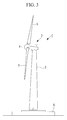
- a wind turbine generator 1 shown in Fig. 3 includes a tower 2 mounted upright on a foundation B, a nacelle 3 installed on the top end of the tower 2, and a rotor head 4 disposed on the nacelle 3 so as to be supported rotatably about a substantially horizontal rotational axis.
- the rotor head 4 has a plurality of (for example, three) wind-turbine rotor blades 5 attached in a radiating pattern around its rotational axis. Thereby, the force of wind striking the wind-turbine rotor blades 5 in the rotational axis direction of the rotor head 4 is converted to motive power rotating the rotor head 4 about the rotational axis.
- the wind turbine generator 1 described above is provided with a gearbox and a generator that are disposed in the nacelle 3 to construct a drivetrain.
- the drivetrain of the wind turbine generator 1 is provided with the generator (not illustrated) and the gearbox 11 linked to a main shaft 10 that rotates together with the rotor head 4.
- This drivetrain is so constructed that the gearbox 10 accelerates the rotation of the rotor head 4 to drive the generator, thereby generating electricity with the generator.
- the above-described wind turbine generator 1 is provided with a lubricating system that achieves lubrication by supplying lubricating oil to sliding parts, such as the drivetrain and the like.
- a lubricating system that achieves lubrication by supplying lubricating oil to sliding parts, such as the drivetrain and the like.
- the lubricating system lubricating the sliding parts an example construction of a lubricating-oil supply system supplying the lubricating-oil to the gearbox 11 and a main bearing 12 that supports the main shaft 10 is explained with reference to Fig. 1 and Fig. 2 .
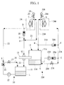
- Fig. 1 illustrates a state (lubricating-oil flow path) in which the lubricating oil flows at the time of lubricating-oil recovery
- Fig. 2 illustrates a state (lubricating-oil flow path) in which the lubricating oil flows during normal operation, showing the respective flow directions of the lubricating oil with arrows.
- opened and closed states of the respective valves those in the closed state are illustrated by filling with solid black.
- a lubricating system 20 of the main bearing 12 achieves lubrication by supplying lubricating oil L to the main bearing 12, which is connected to lubricating-oil piping 23, by circulating the lubricating oil L in a lubricating-oil storage tank (lubricating-oil storage space) 21 through the lubricating-oil piping (lubricating-oil flow path) 23 connected to a lubricating-oil pump 22.
- the lubricating oil L that has lubricated the main bearing 12 is recovered in the lubricating-oil storage tank 21.
- the illustrated lubricating-oil system 20 is provided with an oil cooler 24 between the lubricating-oil pump 22 and the main bearing 12 to prevent an increase in the temperature of the circulating lubricating oil L.
- the illustrated lubricating-oil system 20 is provided with a lubricating-oil recovery line that is formed when the lubricating-oil pump 22 is stopped and in which the lubricating oil L falls naturally and is recovered in the lubricating-oil storage tank 21.
- This lubricating-oil recovery line is constructed of a check valve 25 disposed at a low position at the discharge side of the lubricating-oil piping 23, lubricating-oil return piping (flow path) 26 that is branched off from the vicinity of the downstream side of the check valve 25 and connected to the lubricating-oil storage tank 21, and an automatic opening/closing valve 27 that is disposed in the lubricating-oil return piping 26 and that is closed during normal operation and opened during lubricating-oil recovery.
- the lubricating-oil storage tank 21 and the lubricating-oil pump 22 are located at the lowest position vertically.
- the above-described lubricating-oil system 20 is provided, at the highest position in the lubricating-oil piping 23 forming the lubricating-oil flow path, with an air vent 28 that communicates with the atmosphere at the time of lubricating-oil recovery.
- the air vent 28 is provided with an automatic opening/closing valve 29 that is closed during normal operation and opened at the time of lubricating-oil recovery, and is attached so as to be branched off from an exit piping part of the oil cooler 24 that is disposed at the highest position in the lubricating-oil system 20.
- the above-described automatic opening/closing valves 27 and 29 are both opening/closing valves that are in the fully closed state during normal operation and are fully opened automatically at the time of lubricating-oil recovery; well-known opening/closing valves, such as those of the diaphragm type utilizing a pressure difference of the lubricating oil, which is a fluid, or those that open automatically at the time of power failure, or those that perform opening/closing operation with an emergency electric power source, for example, may be suitably selected for use.
- the illustrated lubricating-oil system 20 is provided with the oil cooler 24 that cools the lubricating oil L, and cooler bypass piping (flow path) 31 that is branched from the lubricating-oil piping 23 and equipped with a check valve 30 is provided at an entrance piping part at the upstream side of this oil cooler 24.
- This cooler bypass piping 31 is connected to the lubricating-oil storage tank 21 through the lubricating-oil piping 23.
- the lubricating oil L in the lubricating-oil storage tank 21 is circulated through the lubricating-oil piping 23, as shown with arrows in the figure.
- the lubricating oil L in the lubricating-oil storage tank 21 is pressurized by the lubricating-oil pump 22 and is discharged to the lubricating-oil piping 23.
- This lubricating oil L passes through the check valve 25, rises in the lubricating-oil piping 23, and flows into the oil cooler 24.
- the lubricating oil L passing through the oil cooler 24 is cooled by heat exchange with the outside air.
- the automatic opening/closing valve 29 disposed in the piping branched off from the branching point C is in a fully closed state, the lubricating oil L will not be discharged outside the piping route through the air vent 28.
- the lubricating oil L cooled in the oil cooler 24 is supplied to the main bearing 12 through the lubricating-oil flow path 23. This lubricating oil L is returned, after lubricating required locations, to the lubricating-oil storage tank 21 through the lubricating-oil piping 23.
- the check valve 30 Since the check valve 30 is fully closed, all of the lubricating oil L passing through the branching point D is supplied to the main bearing 12. However, when the filter of the oil cooler 24 is blocked and the flow path resistance is increased, for example, the check valve 30 is opened due to the pressure increase of the lubricating oil L; thus the lubricating oil L is supplied to the main bearing 12 through the cooler bypass piping 31 that bypasses the oil cooler 24. Thereafter, the lubricating oil L is circulated in the lubricating-oil piping 23 by following a similar route to continuously achieve lubrication of the main bearing 12.
- the operation of the lubricating-oil pump 22 is also stopped.
- the lubricating oil L remaining inside the lubricating-oil piping 23 is recovered to the lubricating-oil storage tank 21 to prevent an increase in the kinematic viscosity of the lubricating oil L in a cold region.
- the lubricating oil L remaining in the lubricating-oil piping 23 at the lubricating-oil pump 22 side of the branching point C falls freely due to gravity to a branching point A located at a lower position, and then flows into the lubricating-oil return flow path 26 in which the automatic opening/closing valve 27 is in the opened state, and is recovered in the lubricating-oil storage tank 21.
- the lubricating oil L remaining in the lubricating-oil piping 23 at the main bearing 12 side of the branching point C falls freely, through the branching point D and the main bearing 12 located at lower positions, into the lubricating-oil storage tank 21 and is recovered therein.
- a lubricating system 20A of the gearbox 11 is explained.
- a casing 11a of the gearbox 11 is used as a lubricating-oil storage tank 21A.
- the lubricating oil L stored in the bottom part of the casing 11a is supplied to the sliding parts of the gearbox 11 through lubricating-oil piping 23A connected to a lubricating-oil pump 22A, and is then recovered in the lubricating-oil storage tank 21A in the bottom part of the casing after lubricating required locations in the gearbox 11.
- the lubricating-oil system 20A in this case is provided with an oil cooler 24A between the lubricating-oil pump 22 and the gearbox 11 to prevent a temperature increase in the lubricating oil L.
- the illustrated lubricating-oil system 20A is provided with a lubricating-oil recovery line that is formed when the lubricating-oil pump 22A is stopped and in which the lubricating oil L falls naturally and is recovered in the lubricating-oil storage tank 21A.
- This lubricating-oil recovery line is constructed of a check valve 25A disposed at a low position at the discharge side of the lubricating-oil piping 23A, lubricating-oil return piping 26A that is branched off from the vicinity of the downstream side of the check valve 25A and connected to the lubricating-oil storage tank 21A, and an automatic opening/closing valve 27A that is disposed in the lubricating-oil return piping 26A and that is closed during normal operation and opened during lubricating-oil recovery.
- the lubricating-oil storage tank 21A is located at the lowest position vertically.
- an air vent 28A is provided at the highest position in the lubricating-oil piping 23A in the above-described lubricating-oil system 20A.
- the air vent 28A is provided with an automatic opening/closing valve 29A that is closed during normal operation and opened at the time of lubricating-oil recovery, and the vent is attached so as to be branched off from an exit piping part of the oil cooler 24A that is disposed at the highest position in the lubricating-oil system 20A.
- the above-described automatic opening/closing valves 27A and 29A are both well-known opening/closing valves that are in the fully closed state during normal operation and are fully opened automatically at the time of lubricating-oil recovery.
- the illustrated lubricating-oil system 20A is provided with the oil cooler 24A that cools the lubricating oil L, and cooler bypass piping 31A that is branched from the lubricating-oil piping 23A and equipped with a check valve 30A is provided at the entrance piping part at the upstream side of this oil cooler 24A.
- This cooler bypass piping 31A is connected to the lubricating-oil storage tank 21A through the lubricating-oil piping 23A.
- the lubricating oil L in the lubricating-oil storage tank 21A is pressurized by the lubricating-oil pump 21A and circulated through the lubricating-oil piping 23A.
- This lubricating oil L passes through the check valve 25A by forcedly opening it, rises in the lubricating-oil piping 23A, and flows into the oil cooler 24A.
- the check valve 30A is also closed by the biasing force of a spring provided inside; thus, all of the lubricating-oil passing through the branching point F is guided to the oil cooler 24A.
- the lubricating oil L passing through the oil cooler 24A is cooled by heat exchange with the outside air.
- the automatic opening/closing valve 29A disposed in the piping branched off from the branching point G is in a fully closed state, the lubricating oil L will not be discharged outside the piping route through the air vent 28A.
- the lubricating oil L cooled in the oil cooler 24A is supplied to the gearbox 11 through the lubricating-oil flow path 23A.
- This lubricating oil L is returned, after lubricating required locations within the gearbox 11, to the lubricating-oil storage tank 21A through the lubricating-oil piping 23A.
- the lubricating oil L remaining in the lubricating-oil piping 23A at the lubricating-oil pump 22A side of the branching point C falls freely due to gravity to the branching point E located at a lower position, flows into the lubricating-oil return flow path 26A in which the automatic opening/closing valve 27A is in the opened state, and is recovered in the lubricating-oil storage tank 21A.
- the lubricating oil L remaining in the lubricating-oil piping 23A at the gearbox 11 side of the branching point G falls freely, through the branching point H and the gearbox 11 located at lower positions, into the lubricating-oil storage tank 21A and is recovered therein.
- the wind turbine generator 1 of the present invention is provided with the lubricating systems 20 and 20A that circulate the lubricating oil L in the lubricating-oil storage tanks 21 and 21A through the lubricating-oil piping 23 and 23A connected to the lubricating-oil pumps 22 and 22A, supply the lubricating oil L to the sliding parts in the main bearing 12 and the gearbox 11 connected to the lubricating-oil piping 23 and 23A, and lubricate them.
- These lubricating systems 20 and 20A are provided with the lubricating-oil recovery lines formed when the lubricating-oil pumps 22 and 22A are stopped.
- These lubricating-oil recovery lines are capable of recovering the lubricating oil L in the lubricating-oil storage tanks 21 and 21A through the lubricating-oil piping 23 and 23A and the lubricating-oil return piping 26 and 26A in which the lubricating oil falls naturally.
- the lubricating systems 20 and 20A can clear the lubricating oil remaining in the lubricating-oil piping 23 and 23A at the time of lubricating-oil recovery, during which the operation of the lubricating-oil pumps 21 and 21A is stopped at the time of power failure or when the wind turbine generator 1 is stopped.
- the automatic opening/closing valves 27 and 27A of the lubricating-oil return flow paths 26 and 26A are opened to form the lubricating-oil recovery line; therefore, the lubricating oil L remaining above the check valves 25 and 25A that are at the discharging side of the lubricating-oil piping 23 and 23A and on the upstream side of the branching points C and G located at the highest positions in the lubricating-oil piping 23 and 23A falls naturally due to gravity and is recovered in the lubricating-oil storage tanks 21 and 21A through the lubricating-oil return flow paths 26 and 26A.
- the lubricating oil L remaining on downstream side of the branching points C and G located at the highest position in the lubricating-oil piping 23 and 23A naturally falls in the lubricating-oil piping 23 and 23A as it is and is recovered in the lubricating-oil storage tanks 21 and 21A.
- the air vents 28 and 28A are disposed at the branching points C and G located at the highest positions in the lubricating-oil piping 23 and 23A and communicate with the atmosphere at the time of lubricating-oil recovery; thereby, at the time of lubricating-oil recovery, the lubricating oil L in the lubricating-oil piping 23 and 23A is immediately separated to the upstream side and the downstream side from the highest positions in the lubricating-oil piping 23 and 23A. As a result, the clearly separated lubricating oil L is recovered smoothly, through the respective lubricating-oil return flow paths 26 and 26A and the lubricating-oil piping 23 and 23A.
- the lubricating oil L can be surely recovered from the lubricating-oil piping 23 and 23A of the lubricating-oil systems 20 and 20A when the lubricating-oil pumps 22 and 22A are stopped, even when the generator is installed in a cold region where there is concern about an increase in the kinematic viscosity of the lubricating-oil L, it is possible to completely eliminate heater heating of the lubricating-oil piping 23 and 23A or reduce the number of heater heating locations to the minimum requirement.
- there will be no lubricating oil L remaining in the lubricating-oil piping 23 and 23A at the downstream side of the check valves 25 and 25A there will be no need to provide heaters at this section for heating.
- the oil coolers 24 and 24A, the air vents 28 and 28A, and the cooler bypass piping 31 and 31A are provided, these are not essential elements and may be optionally provided, as required.
- the lubricating-oil return piping 26 and 26A provided with the automatic opening/closing valves 27 and 27A although there is one set thereof in the above-described embodiment, in order to clear the remaining lubricating oil L completely, the number of sets will be suitably changed depending on the number of vertical levels of the lubricating-oil piping 23 and 23A.
Landscapes
- Engineering & Computer Science (AREA)
- General Engineering & Computer Science (AREA)
- Chemical & Material Sciences (AREA)
- Combustion & Propulsion (AREA)
- Mechanical Engineering (AREA)
- Life Sciences & Earth Sciences (AREA)
- Sustainable Development (AREA)
- Sustainable Energy (AREA)
- Wind Motors (AREA)
Abstract
Description
- The present invention relates to wind turbine generators for use in cold regions and, in particular, to a wind turbine generator that can ensure flowability of lubricating-oil during low-temperature starting.
- A wind turbine generator is a device that generates electricity by rotating a rotor head provided with wind-turbine blades with received wind force, and increasing the rotational speed thereof with a gearbox to drive a generator. For this reason, sliding parts requiring lubrication, for example, the gearbox, bearings, and the like, exist in the wind turbine generator, and the generator is provided with a lubricating system for supplying lubricating oil to the sliding parts from a lubricating-oil tank using a lubricating-oil pump.
- In a hydraulic circuit of a hydraulic machine, a structure that easily and reliably ensures warming up operation when starting an engine and heat balance during operation has been proposed. This conventional technology has been constructed so as to provide a cooling flow path and a non-cooling flow path, differing in the presence of an oil cooler, and to be able to select and change flow paths for return oil returning to a lubricating-oil tank with a direction switching valve (for example, see Patent Document 1).
- Patent Document 1: Japanese Unexamined Patent Application, Publication No.
2005-155698 - A wind turbine generator to be installed in a cold region is sometimes started under low-temperature conditions, for example, an outside air temperature of -30 °C or lower, and it is conceivable that the temperature of piping and the equipment itself can reach a low temperature of about -40 °C at starting time. Under such low-temperature conditions, the kinematic viscosity of lubricating oil increases dramatically, and therefore, in order to ensure flowability of the lubricating oil at starting time, it has been required to forcibly heat the lubricating-oil piping with heaters and the like.
- Specifically, when the lubricating-oil pump is stopped during a power failure or when the wind turbine generator is stopped, the lubricating oil being circulated will remain in the lubricating-oil piping. At this time, if the surrounding environment is at low temperature, the lubricating oil remaining within the lubricating-oil piping is cooled, and therefore, the kinematic viscosity thereof is increased, thus deteriorating its flowability. As a result, there is concern that, if the lubricating-oil pump is started in the state where the kinematic viscosity of the lubricating oil is high, the pump load is increased due to the increased pressure loss, and problems such as pump trip and the like may occur.
Consequently, especially with regard to the part of the lubricating-oil piping where lubricating oil remains, a countermeasure is necessary for heating the entire piping. - However, heating of the part where the lubricating oil remains using a heater involves, in addition to consumption of additional energy, a risk that when a defect occurs in the heater, increased kinematic viscosity of the lubricating oil cannot be avoided. Therefore, in order to improve reliability of a wind turbine generator in a cold region, it is desirable to either completely eliminate heater heating of the lubricating-oil piping or to reduce the number of heater heating locations to the minimum requirement.
- An object of the present invention, which has been made in light of the above circumstances, is to provide a wind turbine generator that can either completely eliminate heater heating of the lubricating-oil piping or reduce the number of heater heating locations to the minimum requirement.
- To achieve the above object, the present invention employs the following solutions.
A wind turbine generator according to the present invention comprises a lubricating system that circulates lubricating oil in a lubricating-oil storage space through a lubricating-oil flow path connected to a lubricating-oil pump, to lubricate a sliding part connected to the lubricating-oil flow path by supplying the lubricating oil thereto,
wherein the lubricating system is provided with a lubricating-oil recovery line that is formed when the lubricating-oil pump is stopped and in which the lubricating-oil falls naturally and is recovered in the lubricating-oil storage space. - According to such a wind turbine generator, the lubricating system is provided with the lubricating-oil recovery line that is formed when the lubricating-oil pump is stopped and in which the lubricating oil falls naturally and is recovered in the lubricating-oil storage space; therefore, when the operation of the lubricating-oil pump is stopped at the time of power failure or when the wind turbine generator is stopped, the lubricating-oil recovery line is formed and the lubricating oil in the lubricating system falls naturally and is recovered in the lubricating-oil storage space. Specifically, at the time of lubricating-oil recovery during which the operation of the lubricating-oil pump is stopped due to a power failure or the like, the lubricating oil falls naturally in the lubricating-oil storage space through the lubricating-oil recovery line, thereby making it possible to clear the lubricating-oil remaining in the lubricating-oil flow path.
- In the above-described invention, it is preferable that the lubricating-oil recovery line comprise a check valve disposed at a low position at a discharge side of the lubricating-oil flow path; a lubricating-oil return flow path branched off from the vicinity of a downstream side of the check valve and connected to the lubricating-oil storage space; and an automatic opening/closing valve that is disposed in the lubricating-oil return flow path and that is closed during normal operation and opened at the time of lubricating-oil recovery.
According to such a construction, at the time of lubricating-oil recovery, during which the operation of the lubricating-oil pump is stopped, the lubricating-oil recovery line is formed by opening the automatic opening/closing valve in the lubricating-oil return flow path. Thus, the lubricating-oil remaining above the check valve at the discharge side of the lubricating-oil flow path and on the upstream side of the highest position of the lubricating-oil flow path falls naturally due to gravity, and is recovered in the lubricating-oil storage space through the lubricating-oil return flow path. The lubricating oil on downstream side of the highest position in the flow path falls naturally in the lubricating-oil flow path as it is and is recovered in the lubricating-oil storage space. - In the above-described invention, it is preferable to dispose an air vent that communicates with the atmosphere at the time of lubricating-oil recovery, at the highest position in the lubricating-oil flow path; thereby, at the time of lubricating-oil recovery, the lubricating oil in the lubricating-oil flow path is separated to the upstream side and the downstream side, with the highest position in the lubricating-oil flow path defined as a boundary, and the lubricating oil at the respective sides is smoothly recovered through the lubricating-oil return flow path and the lubricating-oil flow path.
- According to the wind turbine generator of the above-described invention, since the lubricating oil can be recovered from the lubricating-oil flow path of the lubricating-oil system when the lubricating-oil pump is stopped, even when the wind turbine generator is installed in a cold region, it is possible to completely eliminate heater heating of the lubricating-oil piping or reduce the number of heater heating locations to the minimum requirement.
As a result, it is possible to reduce or eliminate the energy consumed for heating the part where the lubricating-oil remains, at the time of power failure or when the wind turbine generator is stopped. In other words, it is possible to provide a wind turbine generator having low running costs. Furthermore, when starting the lubricating-oil pump, since it is possible to prevent malfunctions, such as pump trip, due to the remaining lubricating oil having increased kinematic viscosity, a wind turbine generator having high reliability, consequently, a wind turbine generator having high availability, can be provided. -
- [
Fig. 1] Fig. 1 is a diagram showing a lubricating-oil feed line, in a state during recovery of lubricating oil, as one embodiment of a wind turbine generator according to the present invention. - [
Fig. 2] Fig. 2 is a diagram showing the lubricating-oil feed line, in a state during normal operation, as one embodiment of the wind turbine generator according to the present invention. - [
Fig. 3] Fig. 3 is a diagram showing an example of the overall structure of the wind turbine generator according to the present invention. -
- 1: wind turbine generator
- 3: nacelle
- 4: rotor head
- 5: wind-turbine blade
- 10: main shaft
- 11: gearbox
- 12: main bearing
- 20, 20A: lubricating system
- 21, 21A: lubricating-oil storage tank
- 22, 22A: lubricating-oil pump
- 23, 23A: lubricating-oil piping
- 24, 24A: oil cooler
- 25, 25A: check valve
- 26, 26A: lubricating-oil return piping
- 27, 27A, 29, 29A: automatic opening/closing valve L: lubricating oil
- Best Mode for Carrying Out the Invention
- In the following, an embodiment of the wind turbine generator according to the present invention will be described with reference to
Figs. 1 to 3 .
A wind turbine generator 1 shown inFig. 3 includes atower 2 mounted upright on a foundation B, anacelle 3 installed on the top end of thetower 2, and a rotor head 4 disposed on thenacelle 3 so as to be supported rotatably about a substantially horizontal rotational axis.
The rotor head 4 has a plurality of (for example, three) wind-turbine rotor blades 5 attached in a radiating pattern around its rotational axis. Thereby, the force of wind striking the wind-turbine rotor blades 5 in the rotational axis direction of the rotor head 4 is converted to motive power rotating the rotor head 4 about the rotational axis. - The wind turbine generator 1 described above is provided with a gearbox and a generator that are disposed in the
nacelle 3 to construct a drivetrain.
As shown inFigs. 1 and2 , the drivetrain of the wind turbine generator 1 is provided with the generator (not illustrated) and thegearbox 11 linked to amain shaft 10 that rotates together with the rotor head 4. This drivetrain is so constructed that thegearbox 10 accelerates the rotation of the rotor head 4 to drive the generator, thereby generating electricity with the generator. - The above-described wind turbine generator 1 is provided with a lubricating system that achieves lubrication by supplying lubricating oil to sliding parts, such as the drivetrain and the like. In the following, as an example of the lubricating system lubricating the sliding parts, an example construction of a lubricating-oil supply system supplying the lubricating-oil to the
gearbox 11 and amain bearing 12 that supports themain shaft 10 is explained with reference toFig. 1 andFig. 2 . -
Fig. 1 illustrates a state (lubricating-oil flow path) in which the lubricating oil flows at the time of lubricating-oil recovery, andFig. 2 illustrates a state (lubricating-oil flow path) in which the lubricating oil flows during normal operation, showing the respective flow directions of the lubricating oil with arrows. Regarding opened and closed states of the respective valves, those in the closed state are illustrated by filling with solid black. - First, a lubricating
system 20 of the main bearing 12 is described.
Thislubricating system 20 achieves lubrication by supplying lubricating oil L to themain bearing 12, which is connected to lubricating-oil piping 23, by circulating the lubricating oil L in a lubricating-oil storage tank (lubricating-oil storage space) 21 through the lubricating-oil piping (lubricating-oil flow path) 23 connected to a lubricating-oil pump 22. The lubricating oil L that has lubricated themain bearing 12 is recovered in the lubricating-oil storage tank 21.
Further, the illustrated lubricating-oil system 20 is provided with an oil cooler 24 between the lubricating-oil pump 22 and themain bearing 12 to prevent an increase in the temperature of the circulating lubricating oil L. - The illustrated lubricating-
oil system 20 is provided with a lubricating-oil recovery line that is formed when the lubricating-oil pump 22 is stopped and in which the lubricating oil L falls naturally and is recovered in the lubricating-oil storage tank 21. This lubricating-oil recovery line is constructed of acheck valve 25 disposed at a low position at the discharge side of the lubricating-oil piping 23, lubricating-oil return piping (flow path) 26 that is branched off from the vicinity of the downstream side of thecheck valve 25 and connected to the lubricating-oil storage tank 21, and an automatic opening/closingvalve 27 that is disposed in the lubricating-oil return piping 26 and that is closed during normal operation and opened during lubricating-oil recovery.
In this case, the lubricating-oil storage tank 21 and the lubricating-oil pump 22 are located at the lowest position vertically. - Furthermore, the above-described lubricating-
oil system 20 is provided, at the highest position in the lubricating-oil piping 23 forming the lubricating-oil flow path, with anair vent 28 that communicates with the atmosphere at the time of lubricating-oil recovery. In this case, theair vent 28 is provided with an automatic opening/closingvalve 29 that is closed during normal operation and opened at the time of lubricating-oil recovery, and is attached so as to be branched off from an exit piping part of theoil cooler 24 that is disposed at the highest position in the lubricating-oil system 20.
The above-described automatic opening/closing valves - The illustrated lubricating-
oil system 20 is provided with theoil cooler 24 that cools the lubricating oil L, and cooler bypass piping (flow path) 31 that is branched from the lubricating-oil piping 23 and equipped with acheck valve 30 is provided at an entrance piping part at the upstream side of thisoil cooler 24. This cooler bypass piping 31 is connected to the lubricating-oil storage tank 21 through the lubricating-oil piping 23. - With the
lubricating system 20 so constructed, during the normal operation shown inFig. 2 , by operating the lubricating-oil pump 22, the lubricating oil L in the lubricating-oil storage tank 21 is circulated through the lubricating-oil piping 23, as shown with arrows in the figure.
In other words, the lubricating oil L in the lubricating-oil storage tank 21 is pressurized by the lubricating-oil pump 22 and is discharged to the lubricating-oil piping 23. This lubricating oil L passes through thecheck valve 25, rises in the lubricating-oil piping 23, and flows into theoil cooler 24. At this time, since the automatic opening/closingvalve 27 is closed, all of the lubricating oil L passing through the branching point A is guided to theoil cooler 24.
Furthermore, thecheck valve 30 is also closed by the biasing force of a spring provided inside; thus, all of the lubricating oil passing through the branching point B is guided to theoil cooler 24. However, when the filter of theoil cooler 24 is blocked and the flow path resistance is increased, for example, thecheck valve 30 is opened due to the pressure increase of the lubricating oil L; thus the lubricating oil L is supplied to themain bearing 12 through the cooler bypass piping 31 that bypasses theoil cooler 24. - The lubricating oil L passing through the
oil cooler 24 is cooled by heat exchange with the outside air. During normal operation, since the automatic opening/closingvalve 29 disposed in the piping branched off from the branching point C is in a fully closed state, the lubricating oil L will not be discharged outside the piping route through theair vent 28.
The lubricating oil L cooled in theoil cooler 24 is supplied to themain bearing 12 through the lubricating-oil flow path 23. This lubricating oil L is returned, after lubricating required locations, to the lubricating-oil storage tank 21 through the lubricating-oil piping 23. - Since the
check valve 30 is fully closed, all of the lubricating oil L passing through the branching point D is supplied to themain bearing 12. However, when the filter of theoil cooler 24 is blocked and the flow path resistance is increased, for example, thecheck valve 30 is opened due to the pressure increase of the lubricating oil L; thus the lubricating oil L is supplied to themain bearing 12 through the cooler bypass piping 31 that bypasses theoil cooler 24.
Thereafter, the lubricating oil L is circulated in the lubricating-oil piping 23 by following a similar route to continuously achieve lubrication of themain bearing 12. - Next, when the operation of the wind turbine generator 1 is stopped due to power failure or wind stronger than a prescribed level, the operation of the lubricating-
oil pump 22 is also stopped. When the lubricating-oil pump 22 is stopped in this manner, the lubricating oil L remaining inside the lubricating-oil piping 23 is recovered to the lubricating-oil storage tank 21 to prevent an increase in the kinematic viscosity of the lubricating oil L in a cold region. - At the time of such lubricating-oil recovery, as shown in
Fig. 1 , the operation of the lubricating-oil pump 22 is stopped, and the automatic opening/closing valves
As a result, a state where the branching point C of the lubricating-oil piping 23 communicates with the atmosphere through theair vent 28 is achieved. Therefore, the lubricating oil L remaining in the lubricating-oil piping 23 at the lubricating-oil pump 22 side of the branching point C falls freely due to gravity to a branching point A located at a lower position, and then flows into the lubricating-oilreturn flow path 26 in which the automatic opening/closingvalve 27 is in the opened state, and is recovered in the lubricating-oil storage tank 21. - On the other hand, the lubricating oil L remaining in the lubricating-
oil piping 23 at themain bearing 12 side of the branching point C falls freely, through the branching point D and themain bearing 12 located at lower positions, into the lubricating-oil storage tank 21 and is recovered therein. - Next, a
lubricating system 20A of thegearbox 11 is explained.
In thislubricating system 20A, acasing 11a of thegearbox 11 is used as a lubricating-oil storage tank 21A. In other words, the lubricating oil L stored in the bottom part of thecasing 11a is supplied to the sliding parts of thegearbox 11 through lubricating-oil piping 23A connected to a lubricating-oil pump 22A, and is then recovered in the lubricating-oil storage tank 21A in the bottom part of the casing after lubricating required locations in thegearbox 11.
The lubricating-oil system 20A in this case is provided with an oil cooler 24A between the lubricating-oil pump 22 and thegearbox 11 to prevent a temperature increase in the lubricating oil L. - The illustrated lubricating-
oil system 20A is provided with a lubricating-oil recovery line that is formed when the lubricating-oil pump 22A is stopped and in which the lubricating oil L falls naturally and is recovered in the lubricating-oil storage tank 21A. This lubricating-oil recovery line is constructed of acheck valve 25A disposed at a low position at the discharge side of the lubricating-oil piping 23A, lubricating-oil return piping 26A that is branched off from the vicinity of the downstream side of thecheck valve 25A and connected to the lubricating-oil storage tank 21A, and an automatic opening/closing valve 27A that is disposed in the lubricating-oil return piping 26A and that is closed during normal operation and opened during lubricating-oil recovery.
In this case, the lubricating-oil storage tank 21A is located at the lowest position vertically. - Furthermore, an
air vent 28A is provided at the highest position in the lubricating-oil piping 23A in the above-described lubricating-oil system 20A. In this case, theair vent 28A is provided with an automatic opening/closing valve 29A that is closed during normal operation and opened at the time of lubricating-oil recovery, and the vent is attached so as to be branched off from an exit piping part of the oil cooler 24A that is disposed at the highest position in the lubricating-oil system 20A.
The above-described automatic opening/closing valves - The illustrated lubricating-
oil system 20A is provided with the oil cooler 24A that cools the lubricating oil L, and cooler bypass piping 31A that is branched from the lubricating-oil piping 23A and equipped with acheck valve 30A is provided at the entrance piping part at the upstream side of this oil cooler 24A. This cooler bypass piping 31A is connected to the lubricating-oil storage tank 21A through the lubricating-oil piping 23A. - With the
lubricating system 20A so constructed, during the normal operation shown inFig. 2 , by operating the lubricating-oil pump 22A, the lubricating oil L in the lubricating-oil storage tank 21A is pressurized by the lubricating-oil pump 21A and circulated through the lubricating-oil piping 23A. This lubricating oil L passes through thecheck valve 25A by forcedly opening it, rises in the lubricating-oil piping 23A, and flows into the oil cooler 24A. At this time, since the automatic opening/closing valve 27A is closed, all of the lubricating oil L passing through the branching point E is guided to the oil cooler 24A.
Furthermore, thecheck valve 30A is also closed by the biasing force of a spring provided inside; thus, all of the lubricating-oil passing through the branching point F is guided to the oil cooler 24A. - The lubricating oil L passing through the oil cooler 24A is cooled by heat exchange with the outside air. During normal operation, since the automatic opening/
closing valve 29A disposed in the piping branched off from the branching point G is in a fully closed state, the lubricating oil L will not be discharged outside the piping route through theair vent 28A.
The lubricating oil L cooled in the oil cooler 24A is supplied to thegearbox 11 through the lubricating-oil flow path 23A. This lubricating oil L is returned, after lubricating required locations within thegearbox 11, to the lubricating-oil storage tank 21A through the lubricating-oil piping 23A. At this time, since thecheck valve 30A is fully closed, all of the lubricating oil L passing through the branching point H is supplied to thegearbox 11. In this case, since thecheck valve 30A is opened by the pressure increase of the lubricating oil L, such as when the filter of the oil cooler 24A is blocked, thus increasing the flow path resistance, the lubricating oil L is supplied to thegearbox 11 through the cooler bypass piping 31A that bypasses the oil cooler 24A.
Thereafter, the lubricating oil L is circulated in the lubricating-oil piping 23A by following a similar route to continuously achieve lubrication of thegearbox 11. - Next, at the time of lubricating-oil recovery, during which the operation of the lubricating-
oil pump 22A is to be stopped, as shown inFig. 1 , the operation of the lubricating-oil pump 22A is stopped and the automatic opening/closing valves
As a result, a state where the branching point G of the lubricating-oil piping 23 communicates with the atmosphere through theair vent 28 is achieved. Therefore, the lubricating oil L remaining in the lubricating-oil piping 23A at the lubricating-oil pump 22A side of the branching point C falls freely due to gravity to the branching point E located at a lower position, flows into the lubricating-oilreturn flow path 26A in which the automatic opening/closing valve 27A is in the opened state, and is recovered in the lubricating-oil storage tank 21A. - On the other hand, the lubricating oil L remaining in the lubricating-
oil piping 23A at thegearbox 11 side of the branching point G falls freely, through the branching point H and thegearbox 11 located at lower positions, into the lubricating-oil storage tank 21A and is recovered therein. - In this way, the wind turbine generator 1 of the present invention is provided with the
lubricating systems oil storage tanks oil piping oil pumps main bearing 12 and thegearbox 11 connected to the lubricating-oil piping
Theselubricating systems oil pumps oil storage tanks oil piping - Therefore, the
lubricating systems oil piping oil pumps
Specifically, at the time of lubricating-oil recovery, the automatic opening/closing valves return flow paths check valves oil piping oil piping oil storage tanks return flow paths oil piping oil piping oil storage tanks - Furthermore, the air vents 28 and 28A are disposed at the branching points C and G located at the highest positions in the lubricating-
oil piping oil piping oil piping return flow paths oil piping - As stated above, according to the wind turbine generator 1 of the above-described invention, since the lubricating oil L can be surely recovered from the lubricating-
oil piping oil systems oil pumps oil piping oil piping check valves - As a result, it is possible to reduce or eliminate the energy consumed for heating the part where the lubricating oil remains, at the time of power failure or when the wind turbine generator is stopped.
Furthermore, when starting the lubricating-oil pumps - In the above-described embodiment, although the
oil coolers
Furthermore, with the lubricating-oil return piping 26 and 26A provided with the automatic opening/closing valves oil piping - Furthermore, although the above-described embodiment is applied to the
lubricating systems main bearing 12 and thegearbox 11, it is needless to say that it is also applicable to a lubricating system lubricating the other sliding parts in the wind turbine generator 1 installed in a cold region.
The present invention is not limited to the above-described embodiment and may be modified as appropriate without departing from the spirit thereof.
Claims (3)
- A wind turbine generator comprising a lubricating system that circulates lubricating oil in a lubricating-oil storage space through a lubricating-oil flow path connected to a lubricating-oil pump, to lubricate a sliding part connected to the lubricating-oil flow path by supplying the lubricating oil thereto,
wherein the lubricating system is provided with a lubricating-oil recovery line that is formed when the lubricating-oil pump is stopped and in which the lubricating oil falls naturally and is recovered in the lubricating-oil storage space. - The wind turbine generator according to Claim 1, wherein the lubricating-oil recovery line comprises:a check valve disposed at a low position at a discharge side of the lubricating-oil flow path;a lubricating-oil return flow path branched off from the vicinity of a downstream side of the check valve and connected to the lubricating-oil storage space; andan automatic opening/closing valve that is disposed in the lubricating-oil return flow path and that is closed during normal operation and opened at the time of lubricating-oil recovery.
- The wind turbine generator according to Claim 2, wherein an air vent that communicates with the atmosphere at the time of lubricating-oil recovery is disposed at the highest position in the lubricating-oil flow path.
Applications Claiming Priority (1)
| Application Number | Priority Date | Filing Date | Title |
|---|---|---|---|
| PCT/JP2008/068893 WO2010044171A1 (en) | 2008-10-17 | 2008-10-17 | Wind-driven electricity generator |
Publications (2)
| Publication Number | Publication Date |
|---|---|
| EP2357360A1 true EP2357360A1 (en) | 2011-08-17 |
| EP2357360A4 EP2357360A4 (en) | 2012-11-21 |
Family
ID=42106349
Family Applications (1)
| Application Number | Title | Priority Date | Filing Date |
|---|---|---|---|
| EP08877429A Withdrawn EP2357360A4 (en) | 2008-10-17 | 2008-10-17 | Wind-driven electricity generator |
Country Status (7)
| Country | Link |
|---|---|
| US (1) | US8672093B2 (en) |
| EP (1) | EP2357360A4 (en) |
| JP (1) | JP5031031B2 (en) |
| KR (1) | KR101087518B1 (en) |
| CN (1) | CN101790641B (en) |
| CA (1) | CA2671237C (en) |
| WO (1) | WO2010044171A1 (en) |
Cited By (1)
| Publication number | Priority date | Publication date | Assignee | Title |
|---|---|---|---|---|
| US8869940B2 (en) | 2012-01-17 | 2014-10-28 | General Electric Company | Dual temperature oil control system and method for a wind turbine gearbox |
Families Citing this family (15)
| Publication number | Priority date | Publication date | Assignee | Title |
|---|---|---|---|---|
| KR101203885B1 (en) * | 2010-06-15 | 2012-11-22 | 주식회사 아원 | Wind power generator |
| DE102011008672A1 (en) * | 2011-01-15 | 2012-07-19 | Hydac Filtertechnik Gmbh | Device for lubricating a gearbox and a bearing |
| FR2970504B1 (en) * | 2011-01-19 | 2013-02-08 | Turbomeca | METHOD AND DEVICE FOR SUPPLYING LUBRICANTS |
| CN102913611B (en) * | 2011-08-04 | 2015-08-19 | 华锐风电科技(集团)股份有限公司 | Driftage bearing lubrication of tooth surface controlling method, device and driftage bearing lubrication system |
| CN102374120B (en) * | 2011-09-15 | 2013-12-04 | 新疆金风科技股份有限公司 | Control method and system for wind turbine generator system |
| EP2573388B1 (en) * | 2011-09-22 | 2018-11-07 | Moventas Gears Oy | A method for controlling lubrication of a gear unit and a gear unit |
| WO2014123027A1 (en) * | 2013-02-06 | 2014-08-14 | 本田技研工業株式会社 | Hydraulic pressure feed device for automatic transmission |
| CN103591431B (en) * | 2013-10-22 | 2016-08-24 | 杭州杭发发电设备有限公司 | The oily outer circulation lubricating arrangement of turbine-generator units bearing |
| CN105864412A (en) * | 2016-06-16 | 2016-08-17 | 南京讯联智能科技有限公司 | Novel wind turbine gearbox lubricating and cooling system |
| CN108443478B (en) * | 2018-04-23 | 2024-08-09 | 中国航发哈尔滨东安发动机有限公司 | Lubrication system for main speed reducer test |
| EP3884158B1 (en) * | 2018-11-20 | 2024-06-26 | Vestas Wind Systems A/S | A wind turbine cooling system |
| DE102021208683B3 (en) * | 2021-08-10 | 2023-01-19 | Zf Friedrichshafen Ag | Method of repairing a transmission assembly |
| CN114458538B (en) * | 2022-01-26 | 2024-01-30 | 上海勘测设计研究院有限公司 | Automatic lubrication offshore wind power generation system and working method |
| CN115978423A (en) * | 2023-02-13 | 2023-04-18 | 四川川润液压润滑设备有限公司 | An integrated lubrication system |
| CN116877677B (en) * | 2023-07-24 | 2024-05-28 | 三峡新能源海上风电运维江苏有限公司 | Gear box lubrication cooling system |
Family Cites Families (21)
| Publication number | Priority date | Publication date | Assignee | Title |
|---|---|---|---|---|
| JPS53146069A (en) * | 1977-05-25 | 1978-12-19 | Hitachi Ltd | Lubricating apparatus |
| DE3231016A1 (en) | 1982-08-20 | 1984-02-23 | Thyssen Industrie Ag, 4300 Essen | Planetary gear with circulation lubrication |
| JPH0431611A (en) * | 1990-05-24 | 1992-02-03 | Nippondenso Co Ltd | Lubrication device for internal combustion engine |
| JPH0526024A (en) * | 1991-07-17 | 1993-02-02 | Toyota Motor Corp | Lubricating device of engine |
| JP3853092B2 (en) * | 1998-10-08 | 2006-12-06 | 日野自動車株式会社 | Liquid filter |
| US6360791B2 (en) * | 1998-11-02 | 2002-03-26 | Motorvac Technologies, Inc. | Service equipment for engine cooling systems |
| USRE38232E1 (en) * | 1998-11-02 | 2003-08-26 | Motorvac Technologies, Inc. | Method and apparatus for servicing engine cooling systems |
| WO2003029671A1 (en) | 2001-10-03 | 2003-04-10 | Vestas Wind Systems A/S | Apparatus for lubricating the bearings of an electrical power generator in a wind turbine |
| GB2382117B (en) * | 2001-10-05 | 2005-07-20 | Hansen Transmissions Int | Wind turbine gear unit lubrication |
| US7036634B2 (en) * | 2003-03-25 | 2006-05-02 | Honda Giken Kogyo Kabushiki Kaisha | Transmission lubricant cooling system |
| JP2005155698A (en) | 2003-11-21 | 2005-06-16 | Sumitomo (Shi) Construction Machinery Manufacturing Co Ltd | Hydraulic circuit of hydraulic work machine |
| JP2005207264A (en) * | 2004-01-21 | 2005-08-04 | Ntn Corp | Bearing for small wind power generator main spindle |
| CN2799889Y (en) * | 2005-06-03 | 2006-07-26 | 四川川润(集团)有限公司 | Dilute oil lubricating device for accelerator of wind power generator |
| JP4993688B2 (en) * | 2006-11-15 | 2012-08-08 | オークマ株式会社 | Spindle lubricator |
| JP4464984B2 (en) * | 2007-04-20 | 2010-05-19 | トヨタ自動車株式会社 | Vehicle oil supply device |
| CN101196176B (en) * | 2007-12-26 | 2010-09-29 | 二重集团(德阳)重型装备股份有限公司 | Low temperature wind-driven generator speed increasing engine oil lubrication system |
| US7997855B2 (en) * | 2008-01-29 | 2011-08-16 | General Electric Company | Lubrication heating system and wind turbine incorporating same |
| ES2396138T3 (en) | 2008-06-02 | 2013-02-19 | Vestas Wind Systems A/S | A lubrication system for a gear system for a wind turbine |
| AU2008331348A1 (en) | 2008-08-14 | 2010-03-04 | Mitsubishi Heavy Industries, Ltd. | Wind turbine generator |
| US20100056315A1 (en) * | 2008-08-27 | 2010-03-04 | Scholte-Wassink Hartmut | Fluidic system, a drive train for a wind turbine and a method for actuating a mechanical component |
| DK2184487T3 (en) * | 2008-11-10 | 2011-11-14 | Alstom Wind Slu | Wind turbine lubrication system consisting of a pump for pumping lubricant through a lubrication circuit |
-
2008
- 2008-10-17 CN CN2008800016074A patent/CN101790641B/en not_active Expired - Fee Related
- 2008-10-17 WO PCT/JP2008/068893 patent/WO2010044171A1/en not_active Ceased
- 2008-10-17 US US12/520,174 patent/US8672093B2/en not_active Expired - Fee Related
- 2008-10-17 JP JP2009525811A patent/JP5031031B2/en not_active Expired - Fee Related
- 2008-10-17 CA CA2671237A patent/CA2671237C/en not_active Expired - Fee Related
- 2008-10-17 KR KR1020097014033A patent/KR101087518B1/en not_active Expired - Fee Related
- 2008-10-17 EP EP08877429A patent/EP2357360A4/en not_active Withdrawn
Cited By (1)
| Publication number | Priority date | Publication date | Assignee | Title |
|---|---|---|---|---|
| US8869940B2 (en) | 2012-01-17 | 2014-10-28 | General Electric Company | Dual temperature oil control system and method for a wind turbine gearbox |
Also Published As
| Publication number | Publication date |
|---|---|
| WO2010044171A1 (en) | 2010-04-22 |
| CN101790641A (en) | 2010-07-28 |
| CA2671237A1 (en) | 2010-04-17 |
| US20100329869A1 (en) | 2010-12-30 |
| US8672093B2 (en) | 2014-03-18 |
| JP5031031B2 (en) | 2012-09-19 |
| KR101087518B1 (en) | 2011-11-28 |
| JPWO2010044171A1 (en) | 2012-03-08 |
| EP2357360A4 (en) | 2012-11-21 |
| CN101790641B (en) | 2012-07-04 |
| CA2671237C (en) | 2012-07-17 |
| KR20100077128A (en) | 2010-07-07 |
Similar Documents
| Publication | Publication Date | Title |
|---|---|---|
| CA2671237C (en) | Wind turbine generator | |
| EP2570660B1 (en) | Renewable energy type electric power generation device | |
| JP6386375B2 (en) | Wind power generation equipment and gearbox | |
| JP5072994B2 (en) | Wind power generator | |
| CN112682497B (en) | Gearbox system, wind turbine and method for operating a gearbox system | |
| US8052383B2 (en) | Wind turbine, a method for controlling the temperature of fluid flowing in a first temperature control system of a wind turbine and use thereof | |
| US8939259B2 (en) | Wind turbine lubrication system | |
| US9482205B2 (en) | Wind turbine having a heat transfer system | |
| US20110222804A1 (en) | Wind turbine generator | |
| EP2469086A1 (en) | Wind power generator | |
| US20180216638A1 (en) | Wind turbine, control device for same, and control method for same | |
| KR20100126766A (en) | Wind power generator | |
| AU2008331352B2 (en) | Wind turbine generator | |
| KR20100026866A (en) | Cooling lubrication system of wind generating gearbox | |
| WO2013136056A1 (en) | Overhead tank | |
| CN102725522A (en) | Starting method of rotating machine and starting method of wind power generator | |
| CN118499453A (en) | Gear box assembly | |
| TWI354063B (en) | ||
| CN102840107B (en) | Reservation system | |
| AU2008331348A1 (en) | Wind turbine generator | |
| JP2022098908A (en) | Bearing structure for water turbine power generator |
Legal Events
| Date | Code | Title | Description |
|---|---|---|---|
| PUAI | Public reference made under article 153(3) epc to a published international application that has entered the european phase |
Free format text: ORIGINAL CODE: 0009012 |
|
| 17P | Request for examination filed |
Effective date: 20090624 |
|
| AK | Designated contracting states |
Kind code of ref document: A1 Designated state(s): AT BE BG CH CY CZ DE DK EE ES FI FR GB GR HR HU IE IS IT LI LT LU LV MC MT NL NO PL PT RO SE SI SK TR |
|
| DAX | Request for extension of the european patent (deleted) | ||
| A4 | Supplementary search report drawn up and despatched |
Effective date: 20121023 |
|
| RIC1 | Information provided on ipc code assigned before grant |
Ipc: F03D 11/00 20060101AFI20121017BHEP |
|
| 18D | Application deemed to be withdrawn |
Effective date: 20150505 |
|
| STAA | Information on the status of an ep patent application or granted ep patent |
Free format text: STATUS: THE APPLICATION IS DEEMED TO BE WITHDRAWN |
|
| R18D | Application deemed to be withdrawn (corrected) |
Effective date: 20150501 |