EP2356928B1 - Adapter for beverage preparation machines, particularly for making espresso coffee - Google Patents
Adapter for beverage preparation machines, particularly for making espresso coffee Download PDFInfo
- Publication number
- EP2356928B1 EP2356928B1 EP20110153887 EP11153887A EP2356928B1 EP 2356928 B1 EP2356928 B1 EP 2356928B1 EP 20110153887 EP20110153887 EP 20110153887 EP 11153887 A EP11153887 A EP 11153887A EP 2356928 B1 EP2356928 B1 EP 2356928B1
- Authority
- EP
- European Patent Office
- Prior art keywords
- cartridge holder
- adapter
- supporting element
- respect
- cartridges
- Prior art date
- Legal status (The legal status is an assumption and is not a legal conclusion. Google has not performed a legal analysis and makes no representation as to the accuracy of the status listed.)
- Not-in-force
Links
Images







Classifications
-
- A—HUMAN NECESSITIES
- A47—FURNITURE; DOMESTIC ARTICLES OR APPLIANCES; COFFEE MILLS; SPICE MILLS; SUCTION CLEANERS IN GENERAL
- A47J—KITCHEN EQUIPMENT; COFFEE MILLS; SPICE MILLS; APPARATUS FOR MAKING BEVERAGES
- A47J31/00—Apparatus for making beverages
- A47J31/44—Parts or details or accessories of beverage-making apparatus
- A47J31/4403—Constructional details
- A47J31/446—Filter holding means; Attachment of filters to beverage-making apparatus
- A47J31/4467—Filter holding means; Attachment of filters to beverage-making apparatus by means of linear guides, e.g. drawer-type engagement
-
- A—HUMAN NECESSITIES
- A47—FURNITURE; DOMESTIC ARTICLES OR APPLIANCES; COFFEE MILLS; SPICE MILLS; SUCTION CLEANERS IN GENERAL
- A47J—KITCHEN EQUIPMENT; COFFEE MILLS; SPICE MILLS; APPARATUS FOR MAKING BEVERAGES
- A47J31/00—Apparatus for making beverages
- A47J31/06—Filters or strainers for coffee or tea makers ; Holders therefor
- A47J31/0657—Filters or strainers for coffee or tea makers ; Holders therefor for brewing coffee under pressure, e.g. for espresso machines
- A47J31/0668—Filters or strainers for coffee or tea makers ; Holders therefor for brewing coffee under pressure, e.g. for espresso machines specially adapted for cartridges
-
- A—HUMAN NECESSITIES
- A47—FURNITURE; DOMESTIC ARTICLES OR APPLIANCES; COFFEE MILLS; SPICE MILLS; SUCTION CLEANERS IN GENERAL
- A47J—KITCHEN EQUIPMENT; COFFEE MILLS; SPICE MILLS; APPARATUS FOR MAKING BEVERAGES
- A47J31/00—Apparatus for making beverages
- A47J31/24—Coffee-making apparatus in which hot water is passed through the filter under pressure, i.e. in which the coffee grounds are extracted under pressure
- A47J31/34—Coffee-making apparatus in which hot water is passed through the filter under pressure, i.e. in which the coffee grounds are extracted under pressure with hot water under liquid pressure
- A47J31/36—Coffee-making apparatus in which hot water is passed through the filter under pressure, i.e. in which the coffee grounds are extracted under pressure with hot water under liquid pressure with mechanical pressure-producing means
- A47J31/3666—Coffee-making apparatus in which hot water is passed through the filter under pressure, i.e. in which the coffee grounds are extracted under pressure with hot water under liquid pressure with mechanical pressure-producing means whereby the loading of the brewing chamber with the brewing material is performed by the user
- A47J31/3676—Cartridges being employed
-
- A—HUMAN NECESSITIES
- A47—FURNITURE; DOMESTIC ARTICLES OR APPLIANCES; COFFEE MILLS; SPICE MILLS; SUCTION CLEANERS IN GENERAL
- A47J—KITCHEN EQUIPMENT; COFFEE MILLS; SPICE MILLS; APPARATUS FOR MAKING BEVERAGES
- A47J31/00—Apparatus for making beverages
- A47J31/44—Parts or details or accessories of beverage-making apparatus
- A47J31/4403—Constructional details
- A47J31/446—Filter holding means; Attachment of filters to beverage-making apparatus
- A47J31/4471—Filter holding means; Attachment of filters to beverage-making apparatus by means of a hinge
Definitions
- the present invention relates to an adapter for beverage preparation machines, particularly for preparing espresso coffee.
- Adapters for machines for preparing beverages such as espresso coffee are known which comprise generically a supporting element, which is adapted to be connected to the beverage preparation machine, and on which a cartridge holder is mounted which is adapted to contain the cartridge or cartridges through which hot water, dispensed by the machine, is filtered under pressure, in order to obtain the beverage or infusion.
- the cartridge holder is associated with the supporting element in order to allow the operations for loading and/or unloading the cartridges, as well as the arrangement of the cartridge holder in an active position for providing the infusion and in an inactive position to allow the operations for cleaning the adapter.
- this extraction typically can be achieved only by disassembling, where possible and with difficulty on the part of the average user, the cartridge holder from the supporting element.
- FR-A-2873011 discloses a machine for automatically preparing espresso coffee from prepackaged coffee pods comprising a drawer provided with a plurality of housing cavites for receiving the pods and movable in horizontal translation between a position for extracting, a position for loading, and a position for discharging pods, either manually or by means of a pinion mechansim engaging a rack attached to an edge of the drawer.
- the aim of the present invention is to provide an adapter for beverage preparation machines, particularly for preparing espresso coffee, that is structurally simple and easy to use on the part of the user for the operations for loading and/or unloading the cartridges, for the operations for providing the infusion, and for performing the operations for cleaning the adapter.
- an object of the present invention is to provide an adapter for beverage preparation machines wherein the cartridge holder can be extracted easily in order to perform the operations for cleaning the adapter.
- Another object of the present invention is to provide a multi-cartridge adapter for beverage preparation machines that provides for the use of even a single cartridge in order to prepare the infusion.
- the adapter for beverage preparation machines particularly for preparing espresso coffee, generally designated by the reference numeral 1, comprises a supporting element 2, which can be associated with water dispensing means of a beverage preparation machine such as, for example, for preparing espresso coffee, and a cartridge holder 4, which is associated with the supporting element 2.
- the water dispensing means are capable of dispensing hot water under pressure, typically water at a temperature of approximately 90 ⁇ 2°C and a pressure of 6 - 9 bar.
- the supporting element 2 is constituted by a hollow body shaped substantially like a parallelepiped, which has, respectively at a lateral face thereof and at its lower face, a front opening 5 and a lower opening 6, for moving the cartridge holder 4.
- the supporting element 2 can engage a traditional machine for preparing espresso coffee, not shown, by means of a standard coupling 7 of the bayonet type.
- Machines for preparing espresso coffee as is known, have at least one coupling of the bayonet type at at least one point for dispensing the hot water under pressure, in order to fix a respective filter basket holder that contains a dose or a cartridge of ground coffee.
- the standard coupling 7 of the adapter 1 is shaped identically to the similar coupling used in traditional filter basket holders, i.e., such as to engage a machine for preparing espresso coffee at the means for dispensing hot water under pressure.
- the adapter 1 replaces the traditional filter basket holders and is thus perfectly compatible with existing machines for preparing espresso coffee, without requiring them to be modified in order to use the invention.
- the standard coupling 7 can engage the corresponding coupling on the machine for preparing espresso coffee so that the dispensing means, once engagement has occurred, communicate with a spreading disc 8, which is arranged between the upper face of the supporting element 2 and the standard coupling 7, said disc 8 having the function of dividing the main water jet dispensed by the dispensing means into two distinct secondary water jets.
- the spreading disc 8 has a channel system 9 which merges into two holes 9a, one for each cartridge 10, for the passage of the water 50 dispensed by the dispensing means, as described hereinafter, inside the cartridges 10.
- the spreading disc 8 is shaped so as to divide the main water jet into a plurality of secondary jets, one for each cartridge 10 provided.
- a closing plate 11 is fixed to the supporting element 2, at its lower opening 6, and delimits in a downward region the internal cavity of the supporting element 2.
- the closing plate 11 has an opening 12, which is arranged at the region in which the infusion is dispensed.
- the cartridge holder 4 is provided by a substantially prism-shaped body the dimensions of which are such that it can be accommodated inside the supporting element 2.
- the cartridge holder 4 can be inserted in the supporting element 2 through the front opening 5 of said supporting element 2 and can move, with respect to the latter, from an infusion dispensing position to a position for loading and/or unloading the cartridges 10 and vice versa, passing through two intermediate positions.
- the adapter 1 comprises at least one guide 13 for the translational motion of the cartridge holder 4 with respect to the supporting element 2.
- the supporting element 2 there are two guides 13 which are arranged laterally with respect to the front opening 5 of the supporting element 2 and two sliders 14 which are defined on the cartridge holder 4 at the sides of the latter that face the sides of the supporting element 2 where the guides 13 are arranged.
- the guides 13 and the sliders 14 can be kinematically reversed, i.e., they can be defined, respectively, on the cartridge holder 4 and on the supporting element 2.
- the guides 13 are defined in an upward region by adapted inner profiles of the lateral shoulders of the supporting element and, in a downward region, by two lateral elements 15, each of which is fixed inside the supporting element 2 at said lateral shoulders.
- this fixing occurs by inserting ribs 16 which are defined on the inner walls of the shoulders of the supporting element 2 in adapted slots 17 which are defined on the lateral elements 15.
- the lateral elements 15 are thus locked against possible sliding motions by means of the closing plate 11, which is fixed to the supporting element 2, by means of screws which are screwed into adapted holes which are provided at the bases of the ribs 16 and pass through the lateral elements 15.
- each of the guides 13 comprises a first straight portion 18, which is adapted to allow a sliding of the cartridge holder 4, by way of the sliders 14, with respect to the supporting element 2, from the first intermediate position to the second one and vice versa.
- each of the guides 13 comprises a second portion 19, which branches off from a first end of the first portion 18 which is adjacent to the front opening 5 of the supporting element 2, and is inclined with respect to the first portion 18 away from the cartridge holder 4.
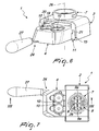
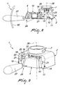
- a first stroke limiter 20 which is adapted to stop the stroke of the cartridge holder 4 with respect to the supporting element 2 when the position for loading and/or unloading the cartridges 10 occurs, as shown in Figures 2-5 .
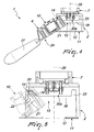
- a second stroke limiter 22 which is adapted to define an abutment for the sliders 14 with which such sliders 14 can be used substantially as a fulcrum for the cartridge holder 4 in the rotary motion, indicated with the arrow 60 in Figure 8 , that leads to the complete separation of the cartridge holder 4 from the supporting element 2.
- each of the guides 13 has a third portion 23, which branches out substantially at right angles to the first portion 18. The third portion 23 thus allows the vertical translational motion of the cartridge holder 4 with respect to the supporting element 2 toward the infusion dispensing position.
- the movement of the cartridge holder 4 with respect to the supporting element 2 along the guides 13 is provided thanks to the presence of movement means 24, which are adapted to move the cartridges 10 toward or away from the dispensing means.
- the movement means 24 comprise a movement ring 25, which is associated with the cartridge holder 4 by means of a cam which is integral with the ring 25, which can produce the translational motion of the cartridge holder 4 along the rotation axis 26 of the movement ring 25 as a consequence of the relative rotation of the movement ring 25 with respect to the axis 26.
- the movement ring 25 can rotate about its own axis 26 and does not perform a translational motion.
- the rotation of the movement ring 25 can be achieved manually by way of the presence of at least one handle 27, which is fixed to the movement ring 25 and is adapted to rotate it with respect to the cartridge holder 4.
- the adapter 1 is of the two-cartridge type.
- the cartridge holder 4 comprises a pair of receptacles 28 for respective cartridges 10 for infusions or the like.
- the preferred number of receptacles 28 is two in number.
- Such receptacles 28 are defined on the upper part of the cartridge holder 4 which faces the dispensing means.
- first means 30a for detecting the presence of the cartridges 10 in the receptacles 28 and first flow control means 31 a for respective ports 32a for the flow of water toward the cartridges 10.
- the first detection means 30a are associated with the first flow control means 31a in order to clear or block the respective flow port 32a respectively in the presence or in the absence of one of the cartridges 10 in the respective receptacle 28.
- first hollow perforators 33a which are fixed to the supporting element 2 and define the respective flow ports 32a through which water 50 is injected into the cartridges 10.
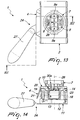
- the first perforators 33a penetrate in the respective cartridges 10 with the cartridge holder 4 arranged in the infusion dispensing position ( Figure 14 ).
- first flow control means 31a provide two normally-closed valves, which operate independently of each other and can be opened in the presence of a respective cartridge 10 in its own receptacle 28.
- Each valve is composed substantially of a flow control element 34, which engages the respective flow port 32a as a consequence of the action of first elastic means 35, for example first helical springs.
- each first flow control means 31a there are two stems 36, which orthogonally protrude into the receptacles 28 and have, as first elastic means 35, the respective first helical springs fitted coaxially over them. If the corresponding cartridge 10 is present, then when the cartridge holder 4 is moved closer to the dispensing means the cartridge 10 pushes the stems 36 toward the dispensing means, overcoming the action of the first elastic means 35 and clearing the flow port 32a from the flow control element 34, which is translationally integral with the two stems 36.
- the second detection means 30b are associated with second flow control means 31b in order to clear or block a respective port 32b for the flow of water respectively in the presence or in the absence of one of the cartridges 10 in the respective receptacle 28.
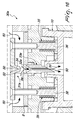
- the second detection means 30b and the second flow control means 31b define, for each of the receptacles 28, a normally-open valve which closes owing to the pressure of the water 50 dispensed by the dispensing means and in the absence of a respective cartridge 10 from the receptacle 28.
- each receptacle 28 there is a cylinder 37, which slides axially along the axis 26 with respect to the supporting element 2 in a respective cylindrical sliding channel 38, which is fixed with respect to the supporting element 2.
- second elastic means 39 which are constituted for example by a second helical spring, which is fitted externally over the cylinder 37 and is interposed between a fixed part of the supporting element 2 and a flange 40 which is integral with the cylinder 37 and is grooved in an upward region.
- the purpose of the second elastic means 39 is to keep open the valve that results from the combination of the second detection means 30b and the second flow control means 31b, both in the condition in which there is a cartridge 10 in the corresponding receptacle 28, and also in the absence of water being dispensed in input and in the absence of a cartridge in the receptacle. This means that the valve remains open when a cartridge is inserted in the receptacle 28 and the cartridge holder 4 is brought to the infusion dispensing position, i.e., the valve is not opened by the cartridge.
- the second elastic means 39 are dimensioned so as to keep the flange 40 in abutment against an abutment wall 41 of the supporting element 2, which is defined at the inlet holes 51 for the water 50 that arrives from the dispensing means.
- each cylinder 37 on the opposite side with respect to the flange 40, there is a perforator 33b, which is adapted to penetrate in the cartridge 10 which is accommodated in the respective receptacle 28 with the cartridge holder 4 arranged in the infusion dispensing position.
- the port 32b for the flow of water 50 is defined in each cylinder 37.
- the flow port 32b is provided by a T-shaped pipe, which has a first portion and a second portion at right angles to the first one.
- the first portion of the T-shaped pipe is coaxial to the respective perforator 33b and is open at the tip thereof in order to communicate with the cartridge 10, while the second portion runs radially through the cylinder 37 from side to side in order to provide more inlets for the water 50 that arrives from the dispensing means.
- the cylinder 37 In the presence of the respective cartridge 10 or in the absence of water 50 under pressure, the cylinder 37, owing to the second elastic means 39 or to the presence of the cartridge 10, is arranged in its upper position, with the flange 40 in abutment against the abutment wall 41.
- a thrust plate 44 which thanks to the presence of third elastic means 45, which consist for example of a third helical spring interposed between the thrust plate 44 and a fixed part of the supporting element 2, push the cartridge 10 that is accommodated in the respective receptacle 28 against the bottom of the receptacle 28, so as to facilitate the removal of the cartridge 10 when the cartridge holder is moved from the infusion dispensing position to the second intermediate position.
- third elastic means 45 which consist for example of a third helical spring interposed between the thrust plate 44 and a fixed part of the supporting element 2, push the cartridge 10 that is accommodated in the respective receptacle 28 against the bottom of the receptacle 28, so as to facilitate the removal of the cartridge 10 when the cartridge holder is moved from the infusion dispensing position to the second intermediate position.
- At least one cartridge 10 is loaded by inserting it into one of the receptacles 28.
- the centre of gravity of the structure that comprises the cartridge holder 4 and the corresponding movement means 24 is located outside the supporting element 2. Accordingly, the cartridge holder 4 tilts autonomously by gravity, since it is substantially hinged by means of the sliders 14 at the first stroke limiter 20, and rests against the closing plate 11 with such an inclination as to direct the upper part, which defines the receptacles 28, toward the user: thus the user has an excellent view for performing the operations for loading and/or unloading the cartridges 10.
- the cartridge holder 4 is brought to the first intermediate position by rotating the handle 27 with respect to the axis of the sliders 14, until a substantially horizontal orientation of the cartridge holder 4 is reached.
- the perforator 33a penetrates in the respective cartridge 10, thus providing a fluid connection between the cartridge 10 and the water dispensing means.
- the cartridges 10, if present, are instead perforated by the perforator 33b and a fluid connection is provided between the cartridges 10 and the water dispensing means.
- the cylinder 37 is pushed into its sliding channel 38 owing to the pressure applied by the water 50 dispensed by the dispensing means away from the latter, closing the ends of the radial portion of the flow port 32b and thus preventing the flow of the water.
- the cartridge holder 4 can be selectively returned to the position for loading and/or unloading the cartridges 10 simply by repeating the procedure described so far in reverse.
- the handle 27 is made to rotate upward with respect to the axis that passes through the sliders 14, so that the sliders can be guided toward the guiding portion 21 and the entire body formed by the cartridge holder and the corresponding movement means 24 is removed from the supporting element 2.
- the adapter according to the present invention fully achieves the intended aim and objects, since it allows the loading and unloading of the cartridges from the cartridge holder by means of a structure that is simple and easy to use.
- Another advantage of the adapter according to the present invention consists in that in addition to the operations for loading and/or unloading the cartridges, it makes it possible to easily perform the operations for providing the infusion and to perform the operations for maintenance or cleaning of the adapter thanks to the easy removability of the cartridge holder from the supporting element.
- a further advantage of the adapter according to the present invention consists in that it is possible to use a plurality of cartridges at a time on traditional beverage preparation machines, without preventing the use of a single cartridge at a time.
- the cartridges illustrated herein are of the rigid type, but the use of flexible cartridges with permeable enclosure, for example E.S.E (Espresso Serving System) cartridges, can be provided.
- E.S.E Espresso Serving System
- the materials used may be any according to requirements and to the state of the art.
Landscapes
- Engineering & Computer Science (AREA)
- Food Science & Technology (AREA)
- Mechanical Engineering (AREA)
- Apparatus For Making Beverages (AREA)
Applications Claiming Priority (1)
| Application Number | Priority Date | Filing Date | Title |
|---|---|---|---|
| ITMI2010A000239A IT1398521B1 (it) | 2010-02-17 | 2010-02-17 | Dispositivo erogatore per macchine per la preparazione di bevande, particolarmente per la produzione di caffe' espresso. |
Publications (2)
| Publication Number | Publication Date |
|---|---|
| EP2356928A1 EP2356928A1 (en) | 2011-08-17 |
| EP2356928B1 true EP2356928B1 (en) | 2012-08-29 |
Family
ID=43066560
Family Applications (1)
| Application Number | Title | Priority Date | Filing Date |
|---|---|---|---|
| EP20110153887 Not-in-force EP2356928B1 (en) | 2010-02-17 | 2011-02-09 | Adapter for beverage preparation machines, particularly for making espresso coffee |
Country Status (4)
| Country | Link |
|---|---|
| US (1) | US8935976B2 (it) |
| EP (1) | EP2356928B1 (it) |
| ES (1) | ES2390570T3 (it) |
| IT (1) | IT1398521B1 (it) |
Families Citing this family (29)
| Publication number | Priority date | Publication date | Assignee | Title |
|---|---|---|---|---|
| DE602007001147D1 (de) * | 2007-03-06 | 2009-07-02 | Nestec Sa | System zur Herstellung eines Getränkes aus einer Kapsel und Verfahren |
| US10722066B2 (en) * | 2010-12-04 | 2020-07-28 | Adrian Rivera | Windowed single serving brewing material holder |
| US11832755B2 (en) * | 2007-07-13 | 2023-12-05 | Adrian Rivera | Brewing material container for a beverage brewer |
| US10071851B2 (en) | 2010-07-12 | 2018-09-11 | Robert Bao Vu | Apparatus and products for producing beverages, and methods for making and using same |
| DK3521209T3 (da) * | 2010-07-22 | 2020-04-27 | K Fee System Gmbh | Portionskapsel med stregkode |
| GB2499004A (en) * | 2012-02-02 | 2013-08-07 | Kraft Foods R & D Inc | Clamping mechanism for a beverage preparation machine |
| EP2869741B1 (en) * | 2012-07-06 | 2016-03-16 | Unilever PLC | Device and method for brewing a beverage |
| EP2887844B1 (en) * | 2012-08-21 | 2017-09-27 | Breville Pty Limited | Portafilter for capsule |
| BR112015006274A2 (pt) | 2012-10-12 | 2017-07-04 | Nestec Sa | cápsula de alimento com múltiplos compartimentos |
| FR3019980B1 (fr) | 2014-04-22 | 2016-05-06 | Unic | Dispositif pour l'extraction d'une substance a infuser |
| KR101433602B1 (ko) | 2014-05-21 | 2014-08-26 | 주식회사 크로버 | 회전식 추출챔버를 구비한 음료생성장치 |
| WO2015193744A1 (en) * | 2014-06-19 | 2015-12-23 | Tentorio Massimo | Single serve brewing machine |
| USD760008S1 (en) | 2014-07-08 | 2016-06-28 | Clover Co., Ltd. | Beverage machine |
| CH709895B1 (it) * | 2014-07-18 | 2018-01-31 | Scacco Sa | Dispositivo di infusione per realizzare una bevanda infusa quale caffè, the, tisane cioccolato. |
| EP3291717B1 (en) * | 2015-05-07 | 2021-06-30 | Smart Wave Technologies, Inc. | Signal and detection system for pairing products |
| US20170252995A1 (en) * | 2016-03-03 | 2017-09-07 | Juicero, Inc. | Juicer cartridge with outlet separator |
| US20170252991A1 (en) * | 2016-03-03 | 2017-09-07 | Juicero, Inc. | Juicer with flexible seal |
| US20170252999A1 (en) * | 2016-03-03 | 2017-09-07 | Juicero, Inc. | Juicer with juicer cartridge orientation feature |
| US20170252993A1 (en) * | 2016-03-03 | 2017-09-07 | Juicero, Inc. | Juicer cartridge with coupling |
| US20170252996A1 (en) * | 2016-03-03 | 2017-09-07 | Juicero, Inc. | Juicer cartridge with secondary flow channel |
| US20170253000A1 (en) * | 2016-03-03 | 2017-09-07 | Juicero, Inc. | Juicer with locking mechanism |
| US20170252990A1 (en) * | 2016-03-03 | 2017-09-07 | Juicero, Inc. | Juicer cartridge geometry |
| US20170252997A1 (en) * | 2016-03-03 | 2017-09-07 | Juicero, Inc. | Juicer cartridge with sanitary seal |
| US20170252998A1 (en) * | 2016-03-03 | 2017-09-07 | Juicero, Inc. | Juicer cartridge with flow disruptor |
| US20170252994A1 (en) * | 2016-03-03 | 2017-09-07 | Juicero, Inc. | Juicing system with juicer cartridge restraints |
| US20170251863A1 (en) * | 2016-03-03 | 2017-09-07 | Juicero, Inc. | Angled juicing system |
| IT201800007714A1 (it) * | 2018-08-01 | 2020-02-01 | Caffe' D'italia Srl | Macchina erogatrice di bevande infuse e simili, particolarmente del tipo a capsule e/o cialde. |
| US11805934B1 (en) * | 2020-10-21 | 2023-11-07 | Adrian Rivera | Brewing material lid and container for a beverage brewer |
| USD1016539S1 (en) | 2022-07-08 | 2024-03-05 | Conair Llc | Combination coffee, capsule/pod and steam machine |
Family Cites Families (8)
| Publication number | Priority date | Publication date | Assignee | Title |
|---|---|---|---|---|
| US3519319A (en) * | 1968-11-06 | 1970-07-07 | Rubbermaid Inc | Removable tilt-down drawer |
| US4314734A (en) * | 1980-05-07 | 1982-02-09 | Sybron Corporation | Cabinet drawer support |
| US4441771A (en) * | 1982-02-08 | 1984-04-10 | Roesler Layton S | Drawer apparatus |
| IT1288773B1 (it) * | 1996-10-22 | 1998-09-24 | Essegielle Srl | Macchina per caffe' espresso. |
| FR2849760B1 (fr) | 2003-01-15 | 2005-08-26 | Unic | Dispositif et machine pour l'extraction d'une substance pour la production de boisson |
| FR2873011B1 (fr) * | 2004-07-16 | 2007-12-14 | Reneka Internat Sarl | Groupe de preparation d'au moins une tasse de cafe de type expresso ou autre boisson chaude a partir d'une dose individuelle preemballee appelee dosette |
| US7140703B1 (en) * | 2004-09-14 | 2006-11-28 | Holdgate Iii Edward | Pull-out and tilt guide assembly for a drawer |
| GB2442935B (en) * | 2006-10-20 | 2009-10-28 | Certwood Ltd | Storage tray system |
-
2010
- 2010-02-17 IT ITMI2010A000239A patent/IT1398521B1/it active
-
2011
- 2011-02-09 EP EP20110153887 patent/EP2356928B1/en not_active Not-in-force
- 2011-02-09 ES ES11153887T patent/ES2390570T3/es active Active
- 2011-02-16 US US13/028,295 patent/US8935976B2/en not_active Expired - Fee Related
Also Published As
| Publication number | Publication date |
|---|---|
| ITMI20100239A1 (it) | 2011-08-18 |
| EP2356928A1 (en) | 2011-08-17 |
| US8935976B2 (en) | 2015-01-20 |
| IT1398521B1 (it) | 2013-03-01 |
| US20110197771A1 (en) | 2011-08-18 |
| HK1157159A1 (en) | 2012-06-29 |
| ES2390570T3 (es) | 2012-11-14 |
Similar Documents
| Publication | Publication Date | Title |
|---|---|---|
| US8935976B2 (en) | Adapter for beverage preparation machines, particularly for making espresso coffee | |
| RU2589576C2 (ru) | Заваривающее устройство для приготовления пищевого продукта | |
| US8479640B2 (en) | Beverage brewing unit | |
| EP4271230B1 (en) | Hybrid receptacle beverage brewing system | |
| EP2109387B1 (en) | Infusion device to prepare beverages from single-serving capsules with capsule centering device | |
| EP2405790B1 (en) | Machine for the preparation of beverages by infusion using cartridges | |
| CN109936993B (zh) | 通过用水冲泡食物制作饮料的设备 | |
| KR20170081653A (ko) | 주입 형태로 음료를 분배하기 위한 기계를 위한 주입 그룹 | |
| HK1157159B (en) | Adapter for beverage preparation machines, particularly for making espresso coffee | |
| EP3603462A1 (en) | Machine for dispensing infused beverages and the like, particularly of the type with capsules and/or pods | |
| AU2012101845B4 (en) | Method of producing a beverage | |
| HK1240476A1 (en) | Infusion group for machines for the dispensing of beverages in the form of infusion | |
| HK1145794A (en) | Beverage brewing unit | |
| HK1162892B (en) | Machine for the preparation of beverages by infusion using cartridges | |
| HK1145618A (en) | Beverage brewing unit | |
| HK1145620A (en) | Beverage brewing unit | |
| HK1145619B (en) | Beverage brewing unit |
Legal Events
| Date | Code | Title | Description |
|---|---|---|---|
| PUAI | Public reference made under article 153(3) epc to a published international application that has entered the european phase |
Free format text: ORIGINAL CODE: 0009012 |
|
| AK | Designated contracting states |
Kind code of ref document: A1 Designated state(s): AL AT BE BG CH CY CZ DE DK EE ES FI FR GB GR HR HU IE IS IT LI LT LU LV MC MK MT NL NO PL PT RO RS SE SI SK SM TR |
|
| AX | Request for extension of the european patent |
Extension state: BA ME |
|
| 17P | Request for examination filed |
Effective date: 20111019 |
|
| GRAP | Despatch of communication of intention to grant a patent |
Free format text: ORIGINAL CODE: EPIDOSNIGR1 |
|
| RIC1 | Information provided on ipc code assigned before grant |
Ipc: A47J 31/06 20060101ALI20111219BHEP Ipc: A47J 31/36 20060101ALI20111219BHEP Ipc: A47J 31/44 20060101AFI20111219BHEP |
|
| GRAS | Grant fee paid |
Free format text: ORIGINAL CODE: EPIDOSNIGR3 |
|
| REG | Reference to a national code |
Ref country code: HK Ref legal event code: DE Ref document number: 1157159 Country of ref document: HK |
|
| GRAA | (expected) grant |
Free format text: ORIGINAL CODE: 0009210 |
|
| AK | Designated contracting states |
Kind code of ref document: B1 Designated state(s): AL AT BE BG CH CY CZ DE DK EE ES FI FR GB GR HR HU IE IS IT LI LT LU LV MC MK MT NL NO PL PT RO RS SE SI SK SM TR |
|
| REG | Reference to a national code |
Ref country code: GB Ref legal event code: FG4D |
|
| REG | Reference to a national code |
Ref country code: CH Ref legal event code: EP |
|
| REG | Reference to a national code |
Ref country code: AT Ref legal event code: REF Ref document number: 572578 Country of ref document: AT Kind code of ref document: T Effective date: 20120915 |
|
| REG | Reference to a national code |
Ref country code: IE Ref legal event code: FG4D |
|
| REG | Reference to a national code |
Ref country code: DE Ref legal event code: R096 Ref document number: 602011000173 Country of ref document: DE Effective date: 20121018 |
|
| REG | Reference to a national code |
Ref country code: NL Ref legal event code: T3 Ref country code: ES Ref legal event code: FG2A Ref document number: 2390570 Country of ref document: ES Kind code of ref document: T3 Effective date: 20121114 |
|
| REG | Reference to a national code |
Ref country code: CH Ref legal event code: NV Representative=s name: PATENTANWAELTE SCHAAD, BALASS, MENZL AND PARTN, CH |
|
| REG | Reference to a national code |
Ref country code: SE Ref legal event code: TRGR |
|
| REG | Reference to a national code |
Ref country code: LT Ref legal event code: MG4D Effective date: 20120829 |
|
| PG25 | Lapsed in a contracting state [announced via postgrant information from national office to epo] |
Ref country code: HR Free format text: LAPSE BECAUSE OF FAILURE TO SUBMIT A TRANSLATION OF THE DESCRIPTION OR TO PAY THE FEE WITHIN THE PRESCRIBED TIME-LIMIT Effective date: 20120829 Ref country code: IS Free format text: LAPSE BECAUSE OF FAILURE TO SUBMIT A TRANSLATION OF THE DESCRIPTION OR TO PAY THE FEE WITHIN THE PRESCRIBED TIME-LIMIT Effective date: 20121229 Ref country code: LT Free format text: LAPSE BECAUSE OF FAILURE TO SUBMIT A TRANSLATION OF THE DESCRIPTION OR TO PAY THE FEE WITHIN THE PRESCRIBED TIME-LIMIT Effective date: 20120829 Ref country code: NO Free format text: LAPSE BECAUSE OF FAILURE TO SUBMIT A TRANSLATION OF THE DESCRIPTION OR TO PAY THE FEE WITHIN THE PRESCRIBED TIME-LIMIT Effective date: 20121129 |
|
| PG25 | Lapsed in a contracting state [announced via postgrant information from national office to epo] |
Ref country code: SI Free format text: LAPSE BECAUSE OF FAILURE TO SUBMIT A TRANSLATION OF THE DESCRIPTION OR TO PAY THE FEE WITHIN THE PRESCRIBED TIME-LIMIT Effective date: 20120829 Ref country code: LV Free format text: LAPSE BECAUSE OF FAILURE TO SUBMIT A TRANSLATION OF THE DESCRIPTION OR TO PAY THE FEE WITHIN THE PRESCRIBED TIME-LIMIT Effective date: 20120829 Ref country code: PT Free format text: LAPSE BECAUSE OF FAILURE TO SUBMIT A TRANSLATION OF THE DESCRIPTION OR TO PAY THE FEE WITHIN THE PRESCRIBED TIME-LIMIT Effective date: 20121231 |
|
| REG | Reference to a national code |
Ref country code: GR Ref legal event code: EP Ref document number: 20120402635 Country of ref document: GR Effective date: 20130122 |
|
| REG | Reference to a national code |
Ref country code: HK Ref legal event code: GR Ref document number: 1157159 Country of ref document: HK |
|
| PG25 | Lapsed in a contracting state [announced via postgrant information from national office to epo] |
Ref country code: RO Free format text: LAPSE BECAUSE OF FAILURE TO SUBMIT A TRANSLATION OF THE DESCRIPTION OR TO PAY THE FEE WITHIN THE PRESCRIBED TIME-LIMIT Effective date: 20120829 Ref country code: EE Free format text: LAPSE BECAUSE OF FAILURE TO SUBMIT A TRANSLATION OF THE DESCRIPTION OR TO PAY THE FEE WITHIN THE PRESCRIBED TIME-LIMIT Effective date: 20120829 Ref country code: CZ Free format text: LAPSE BECAUSE OF FAILURE TO SUBMIT A TRANSLATION OF THE DESCRIPTION OR TO PAY THE FEE WITHIN THE PRESCRIBED TIME-LIMIT Effective date: 20120829 |
|
| PG25 | Lapsed in a contracting state [announced via postgrant information from national office to epo] |
Ref country code: SK Free format text: LAPSE BECAUSE OF FAILURE TO SUBMIT A TRANSLATION OF THE DESCRIPTION OR TO PAY THE FEE WITHIN THE PRESCRIBED TIME-LIMIT Effective date: 20120829 Ref country code: PL Free format text: LAPSE BECAUSE OF FAILURE TO SUBMIT A TRANSLATION OF THE DESCRIPTION OR TO PAY THE FEE WITHIN THE PRESCRIBED TIME-LIMIT Effective date: 20120829 |
|
| PLBE | No opposition filed within time limit |
Free format text: ORIGINAL CODE: 0009261 |
|
| STAA | Information on the status of an ep patent application or granted ep patent |
Free format text: STATUS: NO OPPOSITION FILED WITHIN TIME LIMIT |
|
| PG25 | Lapsed in a contracting state [announced via postgrant information from national office to epo] |
Ref country code: RS Free format text: LAPSE BECAUSE OF FAILURE TO SUBMIT A TRANSLATION OF THE DESCRIPTION OR TO PAY THE FEE WITHIN THE PRESCRIBED TIME-LIMIT Effective date: 20120829 Ref country code: BG Free format text: LAPSE BECAUSE OF FAILURE TO SUBMIT A TRANSLATION OF THE DESCRIPTION OR TO PAY THE FEE WITHIN THE PRESCRIBED TIME-LIMIT Effective date: 20121129 |
|
| 26N | No opposition filed |
Effective date: 20130530 |
|
| REG | Reference to a national code |
Ref country code: DE Ref legal event code: R097 Ref document number: 602011000173 Country of ref document: DE Effective date: 20130530 |
|
| PG25 | Lapsed in a contracting state [announced via postgrant information from national office to epo] |
Ref country code: MC Free format text: LAPSE BECAUSE OF NON-PAYMENT OF DUE FEES Effective date: 20130228 |
|
| PG25 | Lapsed in a contracting state [announced via postgrant information from national office to epo] |
Ref country code: CY Free format text: LAPSE BECAUSE OF FAILURE TO SUBMIT A TRANSLATION OF THE DESCRIPTION OR TO PAY THE FEE WITHIN THE PRESCRIBED TIME-LIMIT Effective date: 20120829 |
|
| REG | Reference to a national code |
Ref country code: IE Ref legal event code: MM4A |
|
| PG25 | Lapsed in a contracting state [announced via postgrant information from national office to epo] |
Ref country code: AL Free format text: LAPSE BECAUSE OF FAILURE TO SUBMIT A TRANSLATION OF THE DESCRIPTION OR TO PAY THE FEE WITHIN THE PRESCRIBED TIME-LIMIT Effective date: 20120829 Ref country code: IE Free format text: LAPSE BECAUSE OF NON-PAYMENT OF DUE FEES Effective date: 20130209 |
|
| PGFP | Annual fee paid to national office [announced via postgrant information from national office to epo] |
Ref country code: SE Payment date: 20140224 Year of fee payment: 4 Ref country code: DK Payment date: 20140121 Year of fee payment: 4 Ref country code: FI Payment date: 20140203 Year of fee payment: 4 |
|
| PGFP | Annual fee paid to national office [announced via postgrant information from national office to epo] |
Ref country code: TR Payment date: 20140120 Year of fee payment: 4 |
|
| PG25 | Lapsed in a contracting state [announced via postgrant information from national office to epo] |
Ref country code: MT Free format text: LAPSE BECAUSE OF FAILURE TO SUBMIT A TRANSLATION OF THE DESCRIPTION OR TO PAY THE FEE WITHIN THE PRESCRIBED TIME-LIMIT Effective date: 20120829 |
|
| PG25 | Lapsed in a contracting state [announced via postgrant information from national office to epo] |
Ref country code: SM Free format text: LAPSE BECAUSE OF FAILURE TO SUBMIT A TRANSLATION OF THE DESCRIPTION OR TO PAY THE FEE WITHIN THE PRESCRIBED TIME-LIMIT Effective date: 20120829 |
|
| PG25 | Lapsed in a contracting state [announced via postgrant information from national office to epo] |
Ref country code: MK Free format text: LAPSE BECAUSE OF FAILURE TO SUBMIT A TRANSLATION OF THE DESCRIPTION OR TO PAY THE FEE WITHIN THE PRESCRIBED TIME-LIMIT Effective date: 20120829 Ref country code: LU Free format text: LAPSE BECAUSE OF NON-PAYMENT OF DUE FEES Effective date: 20130209 Ref country code: HU Free format text: LAPSE BECAUSE OF FAILURE TO SUBMIT A TRANSLATION OF THE DESCRIPTION OR TO PAY THE FEE WITHIN THE PRESCRIBED TIME-LIMIT; INVALID AB INITIO Effective date: 20110209 |
|
| REG | Reference to a national code |
Ref country code: DK Ref legal event code: EBP Effective date: 20150228 |
|
| REG | Reference to a national code |
Ref country code: SE Ref legal event code: EUG |
|
| PG25 | Lapsed in a contracting state [announced via postgrant information from national office to epo] |
Ref country code: FI Free format text: LAPSE BECAUSE OF NON-PAYMENT OF DUE FEES Effective date: 20150209 |
|
| PG25 | Lapsed in a contracting state [announced via postgrant information from national office to epo] |
Ref country code: SE Free format text: LAPSE BECAUSE OF NON-PAYMENT OF DUE FEES Effective date: 20150210 |
|
| PG25 | Lapsed in a contracting state [announced via postgrant information from national office to epo] |
Ref country code: DK Free format text: LAPSE BECAUSE OF NON-PAYMENT OF DUE FEES Effective date: 20150228 |
|
| REG | Reference to a national code |
Ref country code: FR Ref legal event code: PLFP Year of fee payment: 6 |
|
| REG | Reference to a national code |
Ref country code: FR Ref legal event code: PLFP Year of fee payment: 7 |
|
| PG25 | Lapsed in a contracting state [announced via postgrant information from national office to epo] |
Ref country code: TR Free format text: LAPSE BECAUSE OF NON-PAYMENT OF DUE FEES Effective date: 20150209 |
|
| REG | Reference to a national code |
Ref country code: FR Ref legal event code: PLFP Year of fee payment: 8 |
|
| PGFP | Annual fee paid to national office [announced via postgrant information from national office to epo] |
Ref country code: NL Payment date: 20180214 Year of fee payment: 8 |
|
| PGFP | Annual fee paid to national office [announced via postgrant information from national office to epo] |
Ref country code: CH Payment date: 20180227 Year of fee payment: 8 Ref country code: ES Payment date: 20180301 Year of fee payment: 8 Ref country code: DE Payment date: 20180201 Year of fee payment: 8 |
|
| PGFP | Annual fee paid to national office [announced via postgrant information from national office to epo] |
Ref country code: GR Payment date: 20180215 Year of fee payment: 8 Ref country code: BE Payment date: 20180213 Year of fee payment: 8 Ref country code: AT Payment date: 20180223 Year of fee payment: 8 |
|
| REG | Reference to a national code |
Ref country code: DE Ref legal event code: R119 Ref document number: 602011000173 Country of ref document: DE |
|
| REG | Reference to a national code |
Ref country code: CH Ref legal event code: PL |
|
| REG | Reference to a national code |
Ref country code: NL Ref legal event code: MM Effective date: 20190301 |
|
| REG | Reference to a national code |
Ref country code: AT Ref legal event code: MM01 Ref document number: 572578 Country of ref document: AT Kind code of ref document: T Effective date: 20190209 |
|
| REG | Reference to a national code |
Ref country code: BE Ref legal event code: MM Effective date: 20190228 |
|
| PG25 | Lapsed in a contracting state [announced via postgrant information from national office to epo] |
Ref country code: GR Free format text: LAPSE BECAUSE OF NON-PAYMENT OF DUE FEES Effective date: 20190904 |
|
| PG25 | Lapsed in a contracting state [announced via postgrant information from national office to epo] |
Ref country code: AT Free format text: LAPSE BECAUSE OF NON-PAYMENT OF DUE FEES Effective date: 20190209 Ref country code: CH Free format text: LAPSE BECAUSE OF NON-PAYMENT OF DUE FEES Effective date: 20190228 Ref country code: LI Free format text: LAPSE BECAUSE OF NON-PAYMENT OF DUE FEES Effective date: 20190228 |
|
| PG25 | Lapsed in a contracting state [announced via postgrant information from national office to epo] |
Ref country code: DE Free format text: LAPSE BECAUSE OF NON-PAYMENT OF DUE FEES Effective date: 20190903 Ref country code: NL Free format text: LAPSE BECAUSE OF NON-PAYMENT OF DUE FEES Effective date: 20190301 |
|
| PG25 | Lapsed in a contracting state [announced via postgrant information from national office to epo] |
Ref country code: BE Free format text: LAPSE BECAUSE OF NON-PAYMENT OF DUE FEES Effective date: 20190228 |
|
| REG | Reference to a national code |
Ref country code: ES Ref legal event code: FD2A Effective date: 20200327 |
|
| PG25 | Lapsed in a contracting state [announced via postgrant information from national office to epo] |
Ref country code: ES Free format text: LAPSE BECAUSE OF NON-PAYMENT OF DUE FEES Effective date: 20190210 |
|
| PGFP | Annual fee paid to national office [announced via postgrant information from national office to epo] |
Ref country code: FR Payment date: 20230213 Year of fee payment: 13 |
|
| PGFP | Annual fee paid to national office [announced via postgrant information from national office to epo] |
Ref country code: IT Payment date: 20230210 Year of fee payment: 13 Ref country code: GB Payment date: 20230208 Year of fee payment: 13 |
|
| P01 | Opt-out of the competence of the unified patent court (upc) registered |
Effective date: 20230518 |
|
| GBPC | Gb: european patent ceased through non-payment of renewal fee |
Effective date: 20240209 |
|
| PG25 | Lapsed in a contracting state [announced via postgrant information from national office to epo] |
Ref country code: GB Free format text: LAPSE BECAUSE OF NON-PAYMENT OF DUE FEES Effective date: 20240209 |
|
| PG25 | Lapsed in a contracting state [announced via postgrant information from national office to epo] |
Ref country code: FR Free format text: LAPSE BECAUSE OF NON-PAYMENT OF DUE FEES Effective date: 20240229 |
|
| PG25 | Lapsed in a contracting state [announced via postgrant information from national office to epo] |
Ref country code: GB Free format text: LAPSE BECAUSE OF NON-PAYMENT OF DUE FEES Effective date: 20240209 Ref country code: FR Free format text: LAPSE BECAUSE OF NON-PAYMENT OF DUE FEES Effective date: 20240229 |
|
| PG25 | Lapsed in a contracting state [announced via postgrant information from national office to epo] |
Ref country code: IT Free format text: LAPSE BECAUSE OF NON-PAYMENT OF DUE FEES Effective date: 20240209 |