EP2356510B1 - Optical beam steering - Google Patents
Optical beam steering Download PDFInfo
- Publication number
- EP2356510B1 EP2356510B1 EP09753201.4A EP09753201A EP2356510B1 EP 2356510 B1 EP2356510 B1 EP 2356510B1 EP 09753201 A EP09753201 A EP 09753201A EP 2356510 B1 EP2356510 B1 EP 2356510B1
- Authority
- EP
- European Patent Office
- Prior art keywords
- liquid crystal
- polarisation
- regions
- lcos
- tunable phase
- Prior art date
- Legal status (The legal status is an assumption and is not a legal conclusion. Google has not performed a legal analysis and makes no representation as to the accuracy of the status listed.)
- Active
Links
- 230000003287 optical effect Effects 0.000 title claims description 63
- 239000004973 liquid crystal related substance Substances 0.000 claims description 99
- 238000000034 method Methods 0.000 claims description 23
- 230000005684 electric field Effects 0.000 claims description 13
- 229910052710 silicon Inorganic materials 0.000 claims description 12
- 239000010703 silicon Substances 0.000 claims description 12
- 239000004988 Nematic liquid crystal Substances 0.000 claims description 11
- 239000000463 material Substances 0.000 description 15
- VYPSYNLAJGMNEJ-UHFFFAOYSA-N Silicium dioxide Chemical compound O=[Si]=O VYPSYNLAJGMNEJ-UHFFFAOYSA-N 0.000 description 11
- 238000005516 engineering process Methods 0.000 description 10
- 238000000151 deposition Methods 0.000 description 9
- 230000008021 deposition Effects 0.000 description 8
- 238000013459 approach Methods 0.000 description 7
- 239000013598 vector Substances 0.000 description 7
- XUIMIQQOPSSXEZ-UHFFFAOYSA-N Silicon Chemical compound [Si] XUIMIQQOPSSXEZ-UHFFFAOYSA-N 0.000 description 6
- 210000004027 cell Anatomy 0.000 description 5
- 238000003780 insertion Methods 0.000 description 5
- 230000037431 insertion Effects 0.000 description 5
- 239000007788 liquid Substances 0.000 description 5
- 238000004519 manufacturing process Methods 0.000 description 5
- 230000010287 polarization Effects 0.000 description 5
- 229910052681 coesite Inorganic materials 0.000 description 4
- 229910052906 cristobalite Inorganic materials 0.000 description 4
- 238000013461 design Methods 0.000 description 4
- 238000001704 evaporation Methods 0.000 description 4
- 230000008020 evaporation Effects 0.000 description 4
- 239000000377 silicon dioxide Substances 0.000 description 4
- 229910052682 stishovite Inorganic materials 0.000 description 4
- 239000000758 substrate Substances 0.000 description 4
- 229910052905 tridymite Inorganic materials 0.000 description 4
- 239000011248 coating agent Substances 0.000 description 3
- 238000000576 coating method Methods 0.000 description 3
- 238000004891 communication Methods 0.000 description 3
- 230000001419 dependent effect Effects 0.000 description 3
- 230000000694 effects Effects 0.000 description 3
- 239000000835 fiber Substances 0.000 description 3
- 239000011521 glass Substances 0.000 description 3
- 238000007639 printing Methods 0.000 description 3
- 229910052814 silicon oxide Inorganic materials 0.000 description 3
- 238000004528 spin coating Methods 0.000 description 3
- 230000009471 action Effects 0.000 description 2
- 238000003384 imaging method Methods 0.000 description 2
- 239000011159 matrix material Substances 0.000 description 2
- 229920000642 polymer Polymers 0.000 description 2
- 238000012545 processing Methods 0.000 description 2
- 230000004044 response Effects 0.000 description 2
- 238000000926 separation method Methods 0.000 description 2
- 239000004983 Polymer Dispersed Liquid Crystal Substances 0.000 description 1
- 235000004789 Rosa xanthina Nutrition 0.000 description 1
- 241000109329 Rosa xanthina Species 0.000 description 1
- XAGFODPZIPBFFR-UHFFFAOYSA-N aluminium Chemical compound [Al] XAGFODPZIPBFFR-UHFFFAOYSA-N 0.000 description 1
- 229910052782 aluminium Inorganic materials 0.000 description 1
- 239000004411 aluminium Substances 0.000 description 1
- 230000003321 amplification Effects 0.000 description 1
- 230000005540 biological transmission Effects 0.000 description 1
- 239000013078 crystal Substances 0.000 description 1
- 210000002858 crystal cell Anatomy 0.000 description 1
- 239000002178 crystalline material Substances 0.000 description 1
- -1 e.g. Chemical compound 0.000 description 1
- 230000001747 exhibiting effect Effects 0.000 description 1
- 239000005262 ferroelectric liquid crystals (FLCs) Substances 0.000 description 1
- 238000001914 filtration Methods 0.000 description 1
- 230000000873 masking effect Effects 0.000 description 1
- 238000012986 modification Methods 0.000 description 1
- 230000004048 modification Effects 0.000 description 1
- 238000003199 nucleic acid amplification method Methods 0.000 description 1
- 239000004065 semiconductor Substances 0.000 description 1
- 239000007787 solid Substances 0.000 description 1
- 230000003595 spectral effect Effects 0.000 description 1
- 238000003892 spreading Methods 0.000 description 1
- 230000007480 spreading Effects 0.000 description 1
- 238000003860 storage Methods 0.000 description 1
- 230000000007 visual effect Effects 0.000 description 1
Images

Classifications
-
- G—PHYSICS
- G02—OPTICS
- G02F—OPTICAL DEVICES OR ARRANGEMENTS FOR THE CONTROL OF LIGHT BY MODIFICATION OF THE OPTICAL PROPERTIES OF THE MEDIA OF THE ELEMENTS INVOLVED THEREIN; NON-LINEAR OPTICS; FREQUENCY-CHANGING OF LIGHT; OPTICAL LOGIC ELEMENTS; OPTICAL ANALOGUE/DIGITAL CONVERTERS
- G02F1/00—Devices or arrangements for the control of the intensity, colour, phase, polarisation or direction of light arriving from an independent light source, e.g. switching, gating or modulating; Non-linear optics
- G02F1/29—Devices or arrangements for the control of the intensity, colour, phase, polarisation or direction of light arriving from an independent light source, e.g. switching, gating or modulating; Non-linear optics for the control of the position or the direction of light beams, i.e. deflection
- G02F1/31—Digital deflection, i.e. optical switching
-
- G—PHYSICS
- G02—OPTICS
- G02F—OPTICAL DEVICES OR ARRANGEMENTS FOR THE CONTROL OF LIGHT BY MODIFICATION OF THE OPTICAL PROPERTIES OF THE MEDIA OF THE ELEMENTS INVOLVED THEREIN; NON-LINEAR OPTICS; FREQUENCY-CHANGING OF LIGHT; OPTICAL LOGIC ELEMENTS; OPTICAL ANALOGUE/DIGITAL CONVERTERS
- G02F1/00—Devices or arrangements for the control of the intensity, colour, phase, polarisation or direction of light arriving from an independent light source, e.g. switching, gating or modulating; Non-linear optics
- G02F1/29—Devices or arrangements for the control of the intensity, colour, phase, polarisation or direction of light arriving from an independent light source, e.g. switching, gating or modulating; Non-linear optics for the control of the position or the direction of light beams, i.e. deflection
- G02F1/292—Devices or arrangements for the control of the intensity, colour, phase, polarisation or direction of light arriving from an independent light source, e.g. switching, gating or modulating; Non-linear optics for the control of the position or the direction of light beams, i.e. deflection by controlled diffraction or phased-array beam steering
-
- H—ELECTRICITY
- H04—ELECTRIC COMMUNICATION TECHNIQUE
- H04Q—SELECTING
- H04Q11/00—Selecting arrangements for multiplex systems
-
- G—PHYSICS
- G02—OPTICS
- G02F—OPTICAL DEVICES OR ARRANGEMENTS FOR THE CONTROL OF LIGHT BY MODIFICATION OF THE OPTICAL PROPERTIES OF THE MEDIA OF THE ELEMENTS INVOLVED THEREIN; NON-LINEAR OPTICS; FREQUENCY-CHANGING OF LIGHT; OPTICAL LOGIC ELEMENTS; OPTICAL ANALOGUE/DIGITAL CONVERTERS
- G02F1/00—Devices or arrangements for the control of the intensity, colour, phase, polarisation or direction of light arriving from an independent light source, e.g. switching, gating or modulating; Non-linear optics
- G02F1/01—Devices or arrangements for the control of the intensity, colour, phase, polarisation or direction of light arriving from an independent light source, e.g. switching, gating or modulating; Non-linear optics for the control of the intensity, phase, polarisation or colour
- G02F1/13—Devices or arrangements for the control of the intensity, colour, phase, polarisation or direction of light arriving from an independent light source, e.g. switching, gating or modulating; Non-linear optics for the control of the intensity, phase, polarisation or colour based on liquid crystals, e.g. single liquid crystal display cells
- G02F1/133—Constructional arrangements; Operation of liquid crystal cells; Circuit arrangements
- G02F1/1333—Constructional arrangements; Manufacturing methods
- G02F1/1335—Structural association of cells with optical devices, e.g. polarisers or reflectors
- G02F1/133528—Polarisers
- G02F1/13355—Polarising beam splitters [PBS]
-
- G—PHYSICS
- G02—OPTICS
- G02F—OPTICAL DEVICES OR ARRANGEMENTS FOR THE CONTROL OF LIGHT BY MODIFICATION OF THE OPTICAL PROPERTIES OF THE MEDIA OF THE ELEMENTS INVOLVED THEREIN; NON-LINEAR OPTICS; FREQUENCY-CHANGING OF LIGHT; OPTICAL LOGIC ELEMENTS; OPTICAL ANALOGUE/DIGITAL CONVERTERS
- G02F1/00—Devices or arrangements for the control of the intensity, colour, phase, polarisation or direction of light arriving from an independent light source, e.g. switching, gating or modulating; Non-linear optics
- G02F1/01—Devices or arrangements for the control of the intensity, colour, phase, polarisation or direction of light arriving from an independent light source, e.g. switching, gating or modulating; Non-linear optics for the control of the intensity, phase, polarisation or colour
- G02F1/13—Devices or arrangements for the control of the intensity, colour, phase, polarisation or direction of light arriving from an independent light source, e.g. switching, gating or modulating; Non-linear optics for the control of the intensity, phase, polarisation or colour based on liquid crystals, e.g. single liquid crystal display cells
- G02F1/133—Constructional arrangements; Operation of liquid crystal cells; Circuit arrangements
- G02F1/136—Liquid crystal cells structurally associated with a semi-conducting layer or substrate, e.g. cells forming part of an integrated circuit
- G02F1/1362—Active matrix addressed cells
- G02F1/136277—Active matrix addressed cells formed on a semiconductor substrate, e.g. of silicon
-
- G—PHYSICS
- G02—OPTICS
- G02F—OPTICAL DEVICES OR ARRANGEMENTS FOR THE CONTROL OF LIGHT BY MODIFICATION OF THE OPTICAL PROPERTIES OF THE MEDIA OF THE ELEMENTS INVOLVED THEREIN; NON-LINEAR OPTICS; FREQUENCY-CHANGING OF LIGHT; OPTICAL LOGIC ELEMENTS; OPTICAL ANALOGUE/DIGITAL CONVERTERS
- G02F1/00—Devices or arrangements for the control of the intensity, colour, phase, polarisation or direction of light arriving from an independent light source, e.g. switching, gating or modulating; Non-linear optics
- G02F1/01—Devices or arrangements for the control of the intensity, colour, phase, polarisation or direction of light arriving from an independent light source, e.g. switching, gating or modulating; Non-linear optics for the control of the intensity, phase, polarisation or colour
- G02F1/13—Devices or arrangements for the control of the intensity, colour, phase, polarisation or direction of light arriving from an independent light source, e.g. switching, gating or modulating; Non-linear optics for the control of the intensity, phase, polarisation or colour based on liquid crystals, e.g. single liquid crystal display cells
- G02F1/137—Devices or arrangements for the control of the intensity, colour, phase, polarisation or direction of light arriving from an independent light source, e.g. switching, gating or modulating; Non-linear optics for the control of the intensity, phase, polarisation or colour based on liquid crystals, e.g. single liquid crystal display cells characterised by the electro-optical or magneto-optical effect, e.g. field-induced phase transition, orientation effect, guest-host interaction or dynamic scattering
- G02F1/139—Devices or arrangements for the control of the intensity, colour, phase, polarisation or direction of light arriving from an independent light source, e.g. switching, gating or modulating; Non-linear optics for the control of the intensity, phase, polarisation or colour based on liquid crystals, e.g. single liquid crystal display cells characterised by the electro-optical or magneto-optical effect, e.g. field-induced phase transition, orientation effect, guest-host interaction or dynamic scattering based on orientation effects in which the liquid crystal remains transparent
- G02F1/1393—Devices or arrangements for the control of the intensity, colour, phase, polarisation or direction of light arriving from an independent light source, e.g. switching, gating or modulating; Non-linear optics for the control of the intensity, phase, polarisation or colour based on liquid crystals, e.g. single liquid crystal display cells characterised by the electro-optical or magneto-optical effect, e.g. field-induced phase transition, orientation effect, guest-host interaction or dynamic scattering based on orientation effects in which the liquid crystal remains transparent the birefringence of the liquid crystal being electrically controlled, e.g. ECB-, DAP-, HAN-, PI-LC cells
-
- G—PHYSICS
- G02—OPTICS
- G02F—OPTICAL DEVICES OR ARRANGEMENTS FOR THE CONTROL OF LIGHT BY MODIFICATION OF THE OPTICAL PROPERTIES OF THE MEDIA OF THE ELEMENTS INVOLVED THEREIN; NON-LINEAR OPTICS; FREQUENCY-CHANGING OF LIGHT; OPTICAL LOGIC ELEMENTS; OPTICAL ANALOGUE/DIGITAL CONVERTERS
- G02F2203/00—Function characteristic
- G02F2203/06—Polarisation independent
-
- G—PHYSICS
- G02—OPTICS
- G02F—OPTICAL DEVICES OR ARRANGEMENTS FOR THE CONTROL OF LIGHT BY MODIFICATION OF THE OPTICAL PROPERTIES OF THE MEDIA OF THE ELEMENTS INVOLVED THEREIN; NON-LINEAR OPTICS; FREQUENCY-CHANGING OF LIGHT; OPTICAL LOGIC ELEMENTS; OPTICAL ANALOGUE/DIGITAL CONVERTERS
- G02F2203/00—Function characteristic
- G02F2203/58—Multi-wavelength, e.g. operation of the device at a plurality of wavelengths
- G02F2203/585—Add/drop devices
Definitions
- the invention generally relates to optical beam steering apparatuses, an optical add drop multiplexer comprising an optical beam steering apparatus, a liquid crystal device for optical beam steering, and a method of manufacturing a liquid crystal device for optical beam steering. More particularly, the invention may relate to a polarisation diversity reconfigurable optical add drop multiplexer (ROADM).
- ROADM polarisation diversity reconfigurable optical add drop multiplexer
- light entering an input port of a device may have any possible polarisation state and this may be time varying. If such light is routed through a device, it is preferable that the light that appears in the output port has an amplitude, which does not depend on the input polarisation state.
- a device or system preferably 'honours' polarisation, i.e., paths of beams of different polarisation are matched in order to allow operation without disturbance of relative polarisation between the beams of different polarisation.
- polarisation insensitive phase modulation may ensure that the intensity of steered or routed output beams are substantially unaffected by the polarisation state of the input beam.
- polarisation insensitive phase modulation may provide a known, minimal and/or time independent insertion loss.
- An optical device or system may use Liquid Crystals (LC).
- the liquid crystalline molecules in a material exhibiting a nematic or ferroelectric LC phase are typically rod shaped.
- the direction of preferred orientation of such LC molecules in the neighbourhood of any point can be represented by n (a dimensionless unit vector), where n and -n are fully equivalent.
- an LC device has a liquid crystal director that can be regarded as an arrow, which indicates the average preferred orientation of liquid crystalline molecules in a liquid crystal material. Both directions (180 degrees apart) of the arrow are equivalent.
- Ferroelectric liquid crystalline (Sc*) materials switch largely in the plane of a Liquid-Crystal-on-Silicon (LCOS) device.
- LCOS Liquid-Crystal-on-Silicon
- the director changes its orientation in the plane of the device.
- An array of pixels switched such that one of two opposite positions are taken around the director cone produces (under certain conditions) an array with binary phase levels 0 and pi.
- Such a binary phase array produces diffraction peaks in the device output plane that include both the first order (routing) peak and unwanted higher and symmetric orders which results in power loss and potential crosstalk.
- the loss of a device using this effect will not depend on the input polarisation state, i.e. it is polarisation insensitive, but will depend on the LC layer thickness and the switching angle.
- LC may be provided in a Liquid-Crystal-on-Silicon (LCOS) device having the liquid crystalline material on a silicon substrate that is coated with a reflective layer. LC applied to such a reflective substrate may be controllable to allow light to be reflected or blocked.
- a LCOS may comprise a silicon CMOS chip having a reflective coating (e.g., comprising aluminium) that is covered with LC, and a glass layer over the LC.
- optical beam steering continues to provide a need for improvements such as, for example, reduced insertion loss and/or polarisation insensitivity.
- US 5 825 448 A describes a reflective liquid crystalline diffractive light valve for use in a diffractive projection system.
- the liquid crystal cell includes a transparent substrate and a reflective substrate treated to provide alternating stripes that cooperate with the liquid crystal to form liquid crystal domains extending across the thickness of the cell. These produce an appropriate phase difference in light reflected by the cell, irrespective of the polarization of incident light.
- the techniques embodied in the present invention are applicable to the creation of electrically controllable diffractive optical elements for ray optic, integrated optic or fiber optic utilization operated in either transmission or reflection. Diffractive patterns may be lithographically, holographically or interferometrically generated.
- US 5 363 228 A describes an optical switching device for switching arbitrarily polarized optical signal beams.
- the device includes a plurality of polarization-independent switching cells arranged in matrix form. Each polarization-independent switching cell is independently controllable to selectively direct received optical beams along at least a selected one of two axes.
- the device can be three-dimensionally expanded to increase the number of output ports to which the optical beams can be selectively switched, in which case the matrices can share integrally constructed polarization-independent switching cells.
- an optical beam steering apparatus comprising: a splitter arranged to split an optical beam into at least a first part having a first polarisation and a second part having a second polarisation, said first and second polarisations being substantially mutually orthogonal; a first liquid crystal device region arranged to receive said first part and to have director orientation substantially aligned to said first polarisation; and a second liquid crystal device region arranged to receive said second part and to have director orientation substantially aligned to said second polarisation.
- the first and second liquid crystal device regions may be integral to a single liquid-crystal-on-silicon (LCOS) element or device or may be provided within separate LCOS devices. Furthermore, one of both of those regions may comprise nematic liquid crystal.
- the liquid crystal device area of the device/element may be segmented into two, three or more integral regions, with neighbouring regions having mutually orthogonal director orientations.
- the single LCOS device/element may comprise a plurality of LC regions integral to the device/element, the plurality comprising the above first and second LC regions and at least one further LC region, each of the regions arranged adjacent at least one other of the regions, wherein the regions of each pair of adjacent regions have mutually orthogonal director orientations.
- the regions may be arranged as a row of regions of alternating director orientation, or as an array wherein the director orientations alternate in a manner aking to a chequerboard.
- the adjacent regions may be directly adjacent.
- the optical beam steering apparatus may further comprise at least one wide aperture optical circulator, the circulator allowing light to be transmitted to said splitter and received from the splitter.
- an optical add drop multiplexer comprising the optical beam steering apparatus described above.
- the above optical beam steering apparatus may be implemented within an optical add drop multiplexer (OADM) such as a reconfigurable OADM (ROADM).
- OADM optical add drop multiplexer
- ROADM reconfigurable OADM
- the or each LCOS of an embodiment of the present invention implemented within a ROADM may be remotely controllable by electrical signals.
- An OADM may be scaled to have, e.g., 40-80 ports, involving a plurality of implementations of the present invention.
- a liquid crystal device for optical beam steering comprising: a first liquid crystal region; and a second liquid crystal region, wherein said first and second regions have substantially mutually orthogonal director orientations.
- Such a device may provide an element for conveniently implementing polarisation insensitive optical beam processing in a variety of applications such as, e.g., optical beam steering such as in an OADM or in visual display equipment, in particular where a beam is split into mutually orthogonal polarisations.
- the first and second regions of the device may be integral to a single LCOS or may be provided within separate, respective LCOS devices. Furthermore, one or both of those regions may comprise nematic liquid crystal.
- At least one of the first and second liquid crystal regions of the device may comprise a layer of material on LCOS, the layer being for determining director orientation.
- a suitable material may be an oxide of silicon, e.g., SiO 2 .
- a plurality of the above- described devices may be implemented in array.
- a matrix or array of the devices, each device having the first and second liquid crystal regions may be provided within a single optical beam steering apparatus.
- Described herein is a method of manufacturing a liquid crystal device for optical beam steering, the liquid crystal having a first region having a first director orientation and a second region having a second director orientation, the method comprising: a step of treating said first liquid crystal region of said device to have said first director orientation, wherein said first orientation is substantially mutually orthogonal to said second director orientation of said second region of said device.
- the method may further comprise a second step of treating the second liquid crystal region of said device to have said second director orientation. Whether or not this second step is necessary may depend on whether or not the original LC has a known director orientation.
- One or both of said first and second steps may comprise at least one of deposition of a material layer (e.g., of a SiOx or SiO 2 , as described above), rubbing or photoalignment.
- a material layer e.g., of a SiOx or SiO 2 , as described above
- the deposition may be followed by rubbing or photoalignment.
- the deposition may involve evaporation, printing or spin coating, and the material layer may be deposited on top of the reflective coating of a LCOS.
- an optical beam steering apparatus comprising: a splitter arranged to split a beam into at least a first part having a first polarisation and a second part having a second polarisation, said first and second polarisations being substantially mutually orthogonal; a first liquid crystal device region having a first director orientation and a first surface area that is arranged to receive said first part ; and a second liquid crystal device region having a second director orientation and a second surface area that is arranged to receive said second part , wherein said first liquid crystal device region is arranged such that polarisation of said first part when incident on said first surface area is at a first angle relative to said first director orientation , said second liquid crystal device region is arranged such that polarisation of said second part when incident on said second surface area is at a second angle relative to said second director orientation , and one of said first and second angles is substantially +45degrees and the other of said angles is substantially -45 degrees.
- a beam may be split into two mutually orthogonal parts that are incident in parallel on a single LCOS having a single director orientation.
- a plane parallel to the director orientation and normal to the device plane may bisect the substantially 90degree angle defined by the mutually orthogonal beam parts when these parts are incident on the LCOS.
- the effective refractive index experienced by either of the two incident beams may depend on the relative orientation of the electric field vector (determined by the polarisation state) of that beam and the optical indicatrix of the aligned LC material within the device.
- a projection of the director onto the plane of the LCOS device may be +45degrees from the polarisation of the first incident beam part, and a projection of the director onto the plane of the LCOS device part may be -45degrees from the polarisation of the incident second beam part.
- an embodiment may be arranged such that one of the first and second angles is substantially +45degrees and the other of said angles is substantially -45 degrees. Furthermore, while it is advantageous that the angles are equal in magnitude, it may not be necessary that this magnitude is exactly 45degrees even if such an angle may result in minimum insertion loss.
- the first and second liquid crystal regions orientations of the apparatus according to the fourth aspect may comprise nematic liquid crystal.
- characteristics of nematic LC such as switching out of the plane of the LC device may be exploited to allow analog phase control and reduced insertion loss.
- first and second director orientations of those regions may be substantially aligned to one another. This is especially the case if, for example, the first and second liquid crystal regions are integral to a single LCOS.
- the apparatus may further comprise at least one wide aperture optical circulator, which is arranged to transmit light to, and receive light from, the splitter. This may be particularly advantageous if the apparatus is used in a scaled device that has a high density of optical beam steering components corresponding to a plurality of (e.g., 80) wavelength ports in a wavelength division multiplexing (WDM) system.
- WDM wavelength division multiplexing
- Described herein is a Method of optical beam steering, comprising: splitting a beam into at least a first part having a first polarisation and a second part having a second polarisation, said first and second polarisations being substantially mutually orthogonal; transmitting said first part such that polarisation of said first part when incident on a first surface area is at a first angle relative to a first director orientation , a first liquid crystal device region having said first director orientation and said first surface area,transmitting said second part such that polarisation of said second part when incident on a second surface area is at a second angle relative to a second director orientation, a second liquid crystal device region having said second director orientation and said second surface area, wherein said first and second angles are substantially equal in magnitude.
- the first and second angles may be opposite in sign. More particularly, one of the first and second angles may be substantially +45degrees while the other angle is substantially -45 degrees.
- the present invention provides corresponding methods to each of the apparatuses and devices described above, and apparatuses made according to the above described methods, and systems comprising the above apparatuses or devices, or which are implemented using the above method.
- optical beam steering may include, for example, selective wavelength switching such as in an optical add drop multiplexer.
- Polarisation of any of the light beams in any implementation of any embodiment of the present invention may be at any point on the Poincare sphere, e.g., may be linear or circular.
- the input light may be split (e.g., using a Polarisation Beam Splitter (PBS)) into two mutually orthogonal components which then take separate paths in space until switching has been performed on the components.
- PBS Polarisation Beam Splitter
- the components may not be recombined before switching. Since, in general, no matter what the input polarisation state is, it can always be represented by two mutually orthogonal linear polarisation states, separating the incident light into two components in this way may thus imply no theoretical loss. If the polarisation of the incoming beam changes this may simply couple light in a different proportion between the two incident beams, i.e., one beam's loss is the other beam's gain. If both beams see the same phase modulation (which phase modulation may route the beams to the output port), the device may then be polarisation insensitive. Thus, any of the embodiments described herein may provide a method of polarisation insensitive phase modulation.
- polarisation insensitivity may be improved by the following:
- a single LCOS approach may reduce costs in a scaled device, e.g., an OADM having, e.g., 40 - 80 ports.
- phase levels are available. However, this is difficult to achieve using LC materials which switch in the plane of the device. Further phase levels are possible if the director tilts into the device. In this case, polarisation insensitive phase modulation may not be guaranteed and steps may need to be taken to ensure polarisation insensitive operation.
- One idea might be to introduce a quarter wave plate.
- the present invention according to any of the herein described embodiments uses nematic liquid crystal.
- Nematic Liquid Crystal (LC) materials may switch out of the plane of the LC device.
- the director of such nematic LC is not aligned to the polarisation of a beam, the beam sees the ordinary refractive index of the LC (n ⁇ ).
- an electric field applied to a Nematic LC may tilt the director out of the plane of the device in an analogue manner, so that analogue phase levels are possible. This may, for example, allow a blazed phase profile to be written to the device. Such a phase profile may be used to steer the output beam to an output port without generating second and higher order spots.
- nematic LCs are generally optically anisotropic (usually uniaxial)
- the refractive index experienced by the electric field vector of an incoming ray of light may depend on the electric field vector orientation with respect to the optic axis.
- the LC device is not polarisation insensitive. Therefore, it may be advantageous to employ methods of ensuring polarisation insensitivity.
- the polarisation states of the incoming beams may be controlled so that both see the same refractive index (preferably n11 to ensure greatest phase depth) ('11' indicates parallel to a director).
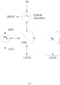
- a first embodiment of the present invention uses a two LCOS approach, e.g., rotating the director between two devices, each device having a LCOS region, so that both beams of light see the same refractive index profile as in (a) above. Such an embodiment is shown in Fig. 1 .
- Director rotation in either or both LC regions of the first embodiment (or any other embodiment of the present invention) may be achieved by deposition (e.g. evaporation), which may be followed by rubbing alignment and/or photoalignment. Any of these techniques may make manufacturing easier.
- the deposition may involve evaporation, printing or spin coating.
- wavelength splitting may be performed prior to the switch.
- the input light may be separated into two beams with orthogonal polarisation states.
- Each beam is directed to its own LCOS device.
- the LCOS devices have substantially mutually orthogonal alignment directions.
- the polarisation orientation states of the light and the alignment direction within the LCOS are selected to be substantially parallel at each LCOS so that both beams 'see' substantially the full depth of the phase modulation pattern displayed. If both polarisations 'see' substantially the same phase profile, the device may be polarisation insensitive.
- the use of an integral quarter wave plate within a device may be needed to rotate the polarisation state of the input beam on reflection. This may be required to ensure that all polarisation states encounter the same net refractive index profile and hence phase delay on passing through the device.
- Such a plate may introduce restrictions on device response time or resolution.
- the first embodiment may increase the available electric fieldwhich can be applied to the LC layer, by not employing a quarter wave plate to ensure polarisation insensitivity. Such a plate may further introduce restrictions on device response time or resolution.
- insertion of a quarter-wave plate within a LCOS structure may require the plate to be provided directly over the pixel. This may have side-effects such as a voltage drop across the plate that reduces the voltage to the LC, and/or field spreading.
- An embodiment such as that of Fig. 1 may further use a wide aperture optical circulator.
- a wide aperture circulator may be advantageous where wavelengths from a plurality of channels are to be split, since it may enable losses on any PBS of an embodiment of the present invention to be avoided.
- a suitable circulator may be as described in the paper " Large-aperture wide field of view optical circulators", M. Roth et al., IEEE PTL 17(10) (2005) pp.2128-30 . According to the abstract of that paper, a free-space optical circulator for large-aperture directional beam separation at 1.55 ⁇ m is described.
- the devices utilize a magnetless Faraday rotator and polymer true zero- order wave-plate to enable an 11-mm clear aperture, high-power handling up to 100 W/cm 2 , and a ⁇ 10° field of view.
- the reader is referred to the entirety of the above paper.
- the above embodiment may equally be implemented using a single LCOS treated to have the two LC regions.
- a single or multiple LCOS approach may be used.
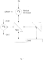
- a second embodiment such as is shown in Fig. 2 employs a single LCOS approach.
- the LCOS may be split into two regions with orthogonal director orientations, or the LCOS may have the same orientation throughout but the orientations of the two incident polarisation states are rotated, e.g., such that each strikes at either side of the director at the same non-zero angle (e.g., 45degrees).
- Fig. 1 and 2 illustrate two possible ways of implementing a polarization insensitive beam steering system using liquid crystal devices with orthogonally aligned LC directors (either as two LCOS devices, or a single LCOS device with two separate areas having orthogonally aligned LC directors).
- the idea of using orthogonally aligned LC directors is generally applicable to any liquid crystal device that uses phase modulation, such as blazed gratings, as mentioned later in this specification with reference to a blazed phase profile.
- The/each liquid crystal device may comprise a plurality of pixels and/or may be a phase modulation liquid crystal device such as a hologram or a grating, e.g., a blazed grating.
- orthogonal polarisations are directed to different region, e.g., half, of a single LCOS device.
- the device may have been treated to have substantially mutually orthogonal alignment for the LC directors of the regions.
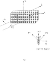
- phase of the input light may be modified by the embodiment of Fig. 3 in the following manner:
- light may be split into two substantially mutually orthogonal polarisation states (P1, P2) and these states may be aligned so that they strike the material at an angle of substantially 45 degrees, for example as described in (b) above.
- P1, P2 substantially mutually orthogonal polarisation states
- each electric field vector may experience the same potential phase modulation depth.
- this technique may allow only the component of the electric field vector parallel to projection of the director onto the incidence plane to actually see the phase profile.
- Such an embodiment may have a fixed loss penalty, e.g., 3dB.
- the polarisation states of the two beams are advantageously mutually orthogonal and lie at angle of substantially 45 degrees to the liquid crystal director, the angles having an opposite sign to one another.
- Such an embodiment may allow the device to be polarisation insensitive.
- the splitter may split a beam into at least a first part having a first polarisation and a second part having a second polarisation, the first and second polarisations being mutually orthogonal.
- a first liquid crystal device region having a first director orientation may receive the first part and, similarly, a second liquid crystal device region having a second director orientation may receive the second part.
- the first and second director orientations may be substantially aligned.
- the first polarisation may be at a first angle to a plane substantially aligned to said director orientations, and the second polarisation a second angle to that plane.
- the first and second angles may be substantially equal and have opposite signs, e.g., one of the angles being substantially +45degrees and the other substantially -45 degrees.
- a plane substantially aligned to said first and second director orientations may bisect the included angle defined by the first and second beam parts, to extend the same angle to each of these parts, albeit opposite in sign.
- phase of the input light may be modified by the fourth embodiment as shown in Fig. 4 in the following manner:
- the second to fourth embodiments may similarly not need a quarter wave plate to ensure polarisation insensitivity and hence the speed and resolution of the nematic device may remain optimal.
- costs may be reduced in comparison to a two LCOS approach.
- the optical loss may be low.
- rubbing alignment, deposition and/or photoalignment may be used to make manufacturing easier.
- Any remaining loss penalty of any embodiment of the present invention may be compensated for by the use of an amplification device.
- any light loss may be used to drop wavelengths, monitor the signals and for other purposes.
- one of more further elements may be added in the path of one or both the split beams, the elements having appropriate shape (e.g., rectangular) to ensure that the path lengths are optically matched.
- Such an element may be for example a glass prism.
- the beam splitter e.g., PBS
- the LCOS element(s) there may be no physical separation between the beam splitter (e.g., PBS) and the LCOS element(s).
- OADM Optical Add Drop Multiplexer
- ROADM reconfigurable OADM
- Any such OADM may be scaled to implement an embodiment of the present invention in respective of a plurality of input and output ports, e.g., 40, 60 or 80.
Landscapes
- Physics & Mathematics (AREA)
- Nonlinear Science (AREA)
- General Physics & Mathematics (AREA)
- Optics & Photonics (AREA)
- Engineering & Computer Science (AREA)
- Chemical & Material Sciences (AREA)
- Crystallography & Structural Chemistry (AREA)
- Computer Networks & Wireless Communication (AREA)
- Microelectronics & Electronic Packaging (AREA)
- Mathematical Physics (AREA)
- Liquid Crystal (AREA)
- Optical Modulation, Optical Deflection, Nonlinear Optics, Optical Demodulation, Optical Logic Elements (AREA)
Applications Claiming Priority (2)
| Application Number | Priority Date | Filing Date | Title |
|---|---|---|---|
| GBGB0820872.0A GB0820872D0 (en) | 2008-11-14 | 2008-11-14 | Optical beam steering |
| PCT/GB2009/051536 WO2010055350A1 (en) | 2008-11-14 | 2009-11-13 | Optical beam steering |
Publications (2)
| Publication Number | Publication Date |
|---|---|
| EP2356510A1 EP2356510A1 (en) | 2011-08-17 |
| EP2356510B1 true EP2356510B1 (en) | 2018-03-07 |
Family
ID=40194652
Family Applications (1)
| Application Number | Title | Priority Date | Filing Date |
|---|---|---|---|
| EP09753201.4A Active EP2356510B1 (en) | 2008-11-14 | 2009-11-13 | Optical beam steering |
Country Status (9)
Families Citing this family (12)
| Publication number | Priority date | Publication date | Assignee | Title |
|---|---|---|---|---|
| GB0820872D0 (en) | 2008-11-14 | 2008-12-24 | Cambridge Entpr Ltd | Optical beam steering |
| US8254732B2 (en) * | 2009-03-11 | 2012-08-28 | Citizen Holdings Co., Ltd. | Phase modulator and optical modulation device |
| JP5600087B2 (ja) * | 2011-09-30 | 2014-10-01 | 日本電信電話株式会社 | 光信号選択スイッチ |
| JP5901321B2 (ja) * | 2012-02-06 | 2016-04-06 | オリンパス株式会社 | 画像表示装置 |
| WO2014015129A1 (en) * | 2012-07-19 | 2014-01-23 | Finisar Corporation | Polarization diverse wavelength selective switch |
| GB2549500A (en) * | 2016-04-19 | 2017-10-25 | Airbus Operations Ltd | Node for an optical network |
| US10551640B2 (en) | 2016-11-21 | 2020-02-04 | Futurewei Technologies, Inc. | Wavelength division multiplexed polarization independent reflective modulators |
| US10222676B2 (en) | 2017-01-27 | 2019-03-05 | Futurewei Technologies, Inc. | Polarization insensitive integrated optical modulator |
| US10330959B2 (en) | 2017-05-22 | 2019-06-25 | Futurewei Technologies, Inc. | Polarization insensitive micro ring modulator |
| US10243684B2 (en) | 2017-05-23 | 2019-03-26 | Futurewei Technologies, Inc. | Wavelength-division multiplexed polarization-insensitive transmissive modulator |
| WO2019165641A1 (en) * | 2018-03-02 | 2019-09-06 | Hong Kong Applied Science and Technology Research Institute Company Limited | Beam-steering apparatus with fast response and enhanced steering resolution |
| DE102018204269A1 (de) * | 2018-03-20 | 2019-09-26 | Osram Gmbh | Anordnung, verfahren für eine anordnung, scheinwerfer und sensorsystem |
Family Cites Families (23)
| Publication number | Priority date | Publication date | Assignee | Title |
|---|---|---|---|---|
| JPH03150525A (ja) | 1989-11-08 | 1991-06-26 | Matsushita Electric Ind Co Ltd | 液晶表示装置 |
| US5111321A (en) * | 1990-10-16 | 1992-05-05 | Bell Communications Research, Inc. | Dual-polarization liquid-crystal etalon filter |
| US5363228A (en) * | 1993-03-05 | 1994-11-08 | General Electric Company | Optical device with spatial light modulators for switching arbitrarily polarized light |
| US5825448A (en) * | 1995-05-19 | 1998-10-20 | Kent State University | Reflective optically active diffractive device |
| US5982518A (en) * | 1996-03-27 | 1999-11-09 | Ciena Corporation | Optical add-drop multiplexers compatible with very dense WDM optical communication systems |
| US5724165A (en) * | 1996-07-23 | 1998-03-03 | Macro-Vision Communications, L.L.C. | Fault-tolerant optical routing switch |
| GB2330422A (en) | 1997-10-17 | 1999-04-21 | Sharp Kk | Reflective liquid crystal device |
| US6807371B1 (en) | 2000-11-27 | 2004-10-19 | Nortel Networks Limited | Reconfigurable add-drop multiplexer |
| US6901175B2 (en) | 2002-02-28 | 2005-05-31 | Engana Ltd. | Tunable wavelength multiplexer |
| US7035484B2 (en) * | 2002-04-12 | 2006-04-25 | Xtellus, Inc. | Tunable optical filter |
| US20030210727A1 (en) | 2002-05-07 | 2003-11-13 | Engana Pty Ltd. | Narrowband filter method and apparatus |
| US6760149B2 (en) | 2002-07-08 | 2004-07-06 | Nortel Networks Limited | Compensation of polarization dependent loss |
| US7092599B2 (en) * | 2003-11-12 | 2006-08-15 | Engana Pty Ltd | Wavelength manipulation system and method |
| GB0329012D0 (en) | 2003-12-15 | 2004-01-14 | Univ Cambridge Tech | Hologram viewing device |
| GB2411735A (en) * | 2004-03-06 | 2005-09-07 | Sharp Kk | Control of liquid crystal alignment in an optical device |
| US7397980B2 (en) | 2004-06-14 | 2008-07-08 | Optium Australia Pty Limited | Dual-source optical wavelength processor |
| GB0414882D0 (en) * | 2004-07-02 | 2004-08-04 | Univ Cambridge Tech | Liquid crystal device |
| US7787720B2 (en) | 2004-09-27 | 2010-08-31 | Optium Australia Pty Limited | Wavelength selective reconfigurable optical cross-connect |
| US7457547B2 (en) | 2004-11-08 | 2008-11-25 | Optium Australia Pty Limited | Optical calibration system and method |
| US7777848B2 (en) * | 2006-03-02 | 2010-08-17 | Canon Kabushiki Kaisha | Manufacturing method of liquid crystal panel and deuterium oxide surface treatment method of alignment film |
| WO2008130674A1 (en) * | 2007-04-20 | 2008-10-30 | Optium Corporation | Method and apparatus for dispersion mitigation in optical links |
| CN201149637Y (zh) | 2007-12-27 | 2008-11-12 | 红蝶科技(深圳)有限公司 | 微型投影机模块 |
| GB0820872D0 (en) | 2008-11-14 | 2008-12-24 | Cambridge Entpr Ltd | Optical beam steering |
-
2008
- 2008-11-14 GB GBGB0820872.0A patent/GB0820872D0/en not_active Ceased
-
2009
- 2009-11-13 US US13/129,029 patent/US9274400B2/en active Active
- 2009-11-13 EP EP09753201.4A patent/EP2356510B1/en active Active
- 2009-11-13 CN CN2009801545807A patent/CN102282509B/zh active Active
- 2009-11-13 JP JP2011543816A patent/JP5818687B2/ja active Active
- 2009-11-13 ES ES09753201.4T patent/ES2669064T3/es active Active
- 2009-11-13 WO PCT/GB2009/051536 patent/WO2010055350A1/en active Application Filing
- 2009-11-13 BR BRPI0921666A patent/BRPI0921666A2/pt not_active IP Right Cessation
- 2009-11-13 KR KR1020117011688A patent/KR101676763B1/ko active Active
Also Published As
| Publication number | Publication date |
|---|---|
| BRPI0921666A2 (pt) | 2019-09-24 |
| ES2669064T3 (es) | 2018-05-23 |
| EP2356510A1 (en) | 2011-08-17 |
| GB0820872D0 (en) | 2008-12-24 |
| CN102282509A (zh) | 2011-12-14 |
| WO2010055350A1 (en) | 2010-05-20 |
| CN102282509B (zh) | 2013-12-11 |
| JP5818687B2 (ja) | 2015-11-18 |
| KR101676763B1 (ko) | 2016-11-29 |
| JP2012508907A (ja) | 2012-04-12 |
| KR20110097780A (ko) | 2011-08-31 |
| US20110273657A1 (en) | 2011-11-10 |
| US9274400B2 (en) | 2016-03-01 |
Similar Documents
| Publication | Publication Date | Title |
|---|---|---|
| EP2356510B1 (en) | Optical beam steering | |
| EP3474069B1 (en) | Beam deflector and three-dimensional display device including the same | |
| US7333685B2 (en) | Variable optical attenuator systems | |
| JP6027628B2 (ja) | 波長を選択的に切り替える方法および装置 | |
| EP0701710B1 (en) | Frequency-selective optical switch using polarization rotation | |
| EP3291001B1 (en) | Light beam deflecting element, wavelength-selective cross-connect device using same, and optical cross-connect device | |
| US10761392B2 (en) | Polarisation-independent, optical multiplexing and demultiplexing systems based on ferroelectric liquid crystal phase modulators for spatial mode division multiplexing and demultiplexing | |
| CA2378029A1 (en) | Wavelength selective switch | |
| US20030058516A1 (en) | Dynamic spectral equalizer and wavelength selective switch having extremely low polarization dependent loss and polarization mode dispersion | |
| EP3133749B1 (en) | Optical switch based on liquid crystal grating | |
| US9103992B1 (en) | Flexible bandwidth wavelength selective switch | |
| WO2000057665A1 (en) | Optical wavelength add/drop multiplexer | |
| EP2425217A1 (en) | Liquid crystal optical switch configured to reduce polarization dependent loss | |
| Cincotti et al. | Polarization grating-based wavelength selective switches | |
| Frisken et al. | Optical Fiber Telecommunications VIA: Chapter 18. Technology and Applications of Liquid Crystal on Silicon (LCoS) in Telecommunications | |
| CA2324707A1 (en) | Electrooptic polarization and wavelength insensitive beam steering devices |
Legal Events
| Date | Code | Title | Description |
|---|---|---|---|
| PUAI | Public reference made under article 153(3) epc to a published international application that has entered the european phase |
Free format text: ORIGINAL CODE: 0009012 |
|
| 17P | Request for examination filed |
Effective date: 20110608 |
|
| AK | Designated contracting states |
Kind code of ref document: A1 Designated state(s): AT BE BG CH CY CZ DE DK EE ES FI FR GB GR HR HU IE IS IT LI LT LU LV MC MK MT NL NO PL PT RO SE SI SK SM TR |
|
| DAX | Request for extension of the european patent (deleted) | ||
| 17Q | First examination report despatched |
Effective date: 20160428 |
|
| REG | Reference to a national code |
Ref country code: DE Ref legal event code: R079 Ref document number: 602009051114 Country of ref document: DE Free format text: PREVIOUS MAIN CLASS: G02F0001310000 Ipc: G02F0001290000 |
|
| RIC1 | Information provided on ipc code assigned before grant |
Ipc: G02F 1/1335 20060101ALI20170614BHEP Ipc: G02F 1/139 20060101ALI20170614BHEP Ipc: G02F 1/1337 20060101ALI20170614BHEP Ipc: G02F 1/31 20060101ALI20170614BHEP Ipc: G02F 1/29 20060101AFI20170614BHEP Ipc: G02F 1/1362 20060101ALI20170614BHEP |
|
| GRAP | Despatch of communication of intention to grant a patent |
Free format text: ORIGINAL CODE: EPIDOSNIGR1 |
|
| INTG | Intention to grant announced |
Effective date: 20170919 |
|
| GRAS | Grant fee paid |
Free format text: ORIGINAL CODE: EPIDOSNIGR3 |
|
| GRAA | (expected) grant |
Free format text: ORIGINAL CODE: 0009210 |
|
| AK | Designated contracting states |
Kind code of ref document: B1 Designated state(s): AT BE BG CH CY CZ DE DK EE ES FI FR GB GR HR HU IE IS IT LI LT LU LV MC MK MT NL NO PL PT RO SE SI SK SM TR |
|
| REG | Reference to a national code |
Ref country code: GB Ref legal event code: FG4D |
|
| REG | Reference to a national code |
Ref country code: CH Ref legal event code: EP Ref country code: AT Ref legal event code: REF Ref document number: 977187 Country of ref document: AT Kind code of ref document: T Effective date: 20180315 |
|
| REG | Reference to a national code |
Ref country code: DE Ref legal event code: R096 Ref document number: 602009051114 Country of ref document: DE |
|
| REG | Reference to a national code |
Ref country code: IE Ref legal event code: FG4D |
|
| REG | Reference to a national code |
Ref country code: ES Ref legal event code: FG2A Ref document number: 2669064 Country of ref document: ES Kind code of ref document: T3 Effective date: 20180523 |
|
| REG | Reference to a national code |
Ref country code: NL Ref legal event code: MP Effective date: 20180307 |
|
| REG | Reference to a national code |
Ref country code: LT Ref legal event code: MG4D |
|
| PG25 | Lapsed in a contracting state [announced via postgrant information from national office to epo] |
Ref country code: CY Free format text: LAPSE BECAUSE OF FAILURE TO SUBMIT A TRANSLATION OF THE DESCRIPTION OR TO PAY THE FEE WITHIN THE PRESCRIBED TIME-LIMIT Effective date: 20180307 Ref country code: LT Free format text: LAPSE BECAUSE OF FAILURE TO SUBMIT A TRANSLATION OF THE DESCRIPTION OR TO PAY THE FEE WITHIN THE PRESCRIBED TIME-LIMIT Effective date: 20180307 Ref country code: HR Free format text: LAPSE BECAUSE OF FAILURE TO SUBMIT A TRANSLATION OF THE DESCRIPTION OR TO PAY THE FEE WITHIN THE PRESCRIBED TIME-LIMIT Effective date: 20180307 Ref country code: FI Free format text: LAPSE BECAUSE OF FAILURE TO SUBMIT A TRANSLATION OF THE DESCRIPTION OR TO PAY THE FEE WITHIN THE PRESCRIBED TIME-LIMIT Effective date: 20180307 Ref country code: NO Free format text: LAPSE BECAUSE OF FAILURE TO SUBMIT A TRANSLATION OF THE DESCRIPTION OR TO PAY THE FEE WITHIN THE PRESCRIBED TIME-LIMIT Effective date: 20180607 |
|
| REG | Reference to a national code |
Ref country code: AT Ref legal event code: MK05 Ref document number: 977187 Country of ref document: AT Kind code of ref document: T Effective date: 20180307 |
|
| PG25 | Lapsed in a contracting state [announced via postgrant information from national office to epo] |
Ref country code: SE Free format text: LAPSE BECAUSE OF FAILURE TO SUBMIT A TRANSLATION OF THE DESCRIPTION OR TO PAY THE FEE WITHIN THE PRESCRIBED TIME-LIMIT Effective date: 20180307 Ref country code: LV Free format text: LAPSE BECAUSE OF FAILURE TO SUBMIT A TRANSLATION OF THE DESCRIPTION OR TO PAY THE FEE WITHIN THE PRESCRIBED TIME-LIMIT Effective date: 20180307 Ref country code: BG Free format text: LAPSE BECAUSE OF FAILURE TO SUBMIT A TRANSLATION OF THE DESCRIPTION OR TO PAY THE FEE WITHIN THE PRESCRIBED TIME-LIMIT Effective date: 20180607 Ref country code: GR Free format text: LAPSE BECAUSE OF FAILURE TO SUBMIT A TRANSLATION OF THE DESCRIPTION OR TO PAY THE FEE WITHIN THE PRESCRIBED TIME-LIMIT Effective date: 20180608 |
|
| PG25 | Lapsed in a contracting state [announced via postgrant information from national office to epo] |
Ref country code: PL Free format text: LAPSE BECAUSE OF FAILURE TO SUBMIT A TRANSLATION OF THE DESCRIPTION OR TO PAY THE FEE WITHIN THE PRESCRIBED TIME-LIMIT Effective date: 20180307 Ref country code: NL Free format text: LAPSE BECAUSE OF FAILURE TO SUBMIT A TRANSLATION OF THE DESCRIPTION OR TO PAY THE FEE WITHIN THE PRESCRIBED TIME-LIMIT Effective date: 20180307 Ref country code: IT Free format text: LAPSE BECAUSE OF FAILURE TO SUBMIT A TRANSLATION OF THE DESCRIPTION OR TO PAY THE FEE WITHIN THE PRESCRIBED TIME-LIMIT Effective date: 20180307 Ref country code: RO Free format text: LAPSE BECAUSE OF FAILURE TO SUBMIT A TRANSLATION OF THE DESCRIPTION OR TO PAY THE FEE WITHIN THE PRESCRIBED TIME-LIMIT Effective date: 20180307 Ref country code: EE Free format text: LAPSE BECAUSE OF FAILURE TO SUBMIT A TRANSLATION OF THE DESCRIPTION OR TO PAY THE FEE WITHIN THE PRESCRIBED TIME-LIMIT Effective date: 20180307 |
|
| PG25 | Lapsed in a contracting state [announced via postgrant information from national office to epo] |
Ref country code: SK Free format text: LAPSE BECAUSE OF FAILURE TO SUBMIT A TRANSLATION OF THE DESCRIPTION OR TO PAY THE FEE WITHIN THE PRESCRIBED TIME-LIMIT Effective date: 20180307 Ref country code: CZ Free format text: LAPSE BECAUSE OF FAILURE TO SUBMIT A TRANSLATION OF THE DESCRIPTION OR TO PAY THE FEE WITHIN THE PRESCRIBED TIME-LIMIT Effective date: 20180307 Ref country code: SM Free format text: LAPSE BECAUSE OF FAILURE TO SUBMIT A TRANSLATION OF THE DESCRIPTION OR TO PAY THE FEE WITHIN THE PRESCRIBED TIME-LIMIT Effective date: 20180307 Ref country code: AT Free format text: LAPSE BECAUSE OF FAILURE TO SUBMIT A TRANSLATION OF THE DESCRIPTION OR TO PAY THE FEE WITHIN THE PRESCRIBED TIME-LIMIT Effective date: 20180307 |
|
| REG | Reference to a national code |
Ref country code: DE Ref legal event code: R097 Ref document number: 602009051114 Country of ref document: DE |
|
| PG25 | Lapsed in a contracting state [announced via postgrant information from national office to epo] |
Ref country code: PT Free format text: LAPSE BECAUSE OF FAILURE TO SUBMIT A TRANSLATION OF THE DESCRIPTION OR TO PAY THE FEE WITHIN THE PRESCRIBED TIME-LIMIT Effective date: 20180709 |
|
| PLBE | No opposition filed within time limit |
Free format text: ORIGINAL CODE: 0009261 |
|
| STAA | Information on the status of an ep patent application or granted ep patent |
Free format text: STATUS: NO OPPOSITION FILED WITHIN TIME LIMIT |
|
| PG25 | Lapsed in a contracting state [announced via postgrant information from national office to epo] |
Ref country code: DK Free format text: LAPSE BECAUSE OF FAILURE TO SUBMIT A TRANSLATION OF THE DESCRIPTION OR TO PAY THE FEE WITHIN THE PRESCRIBED TIME-LIMIT Effective date: 20180307 |
|
| 26N | No opposition filed |
Effective date: 20181210 |
|
| PG25 | Lapsed in a contracting state [announced via postgrant information from national office to epo] |
Ref country code: SI Free format text: LAPSE BECAUSE OF FAILURE TO SUBMIT A TRANSLATION OF THE DESCRIPTION OR TO PAY THE FEE WITHIN THE PRESCRIBED TIME-LIMIT Effective date: 20180307 |
|
| REG | Reference to a national code |
Ref country code: CH Ref legal event code: PL |
|
| PG25 | Lapsed in a contracting state [announced via postgrant information from national office to epo] |
Ref country code: MC Free format text: LAPSE BECAUSE OF FAILURE TO SUBMIT A TRANSLATION OF THE DESCRIPTION OR TO PAY THE FEE WITHIN THE PRESCRIBED TIME-LIMIT Effective date: 20180307 Ref country code: LU Free format text: LAPSE BECAUSE OF NON-PAYMENT OF DUE FEES Effective date: 20181113 |
|
| REG | Reference to a national code |
Ref country code: BE Ref legal event code: MM Effective date: 20181130 |
|
| REG | Reference to a national code |
Ref country code: IE Ref legal event code: MM4A |
|
| PG25 | Lapsed in a contracting state [announced via postgrant information from national office to epo] |
Ref country code: LI Free format text: LAPSE BECAUSE OF NON-PAYMENT OF DUE FEES Effective date: 20181130 Ref country code: CH Free format text: LAPSE BECAUSE OF NON-PAYMENT OF DUE FEES Effective date: 20181130 |
|
| PG25 | Lapsed in a contracting state [announced via postgrant information from national office to epo] |
Ref country code: FR Free format text: LAPSE BECAUSE OF NON-PAYMENT OF DUE FEES Effective date: 20181130 Ref country code: IE Free format text: LAPSE BECAUSE OF NON-PAYMENT OF DUE FEES Effective date: 20181113 |
|
| PG25 | Lapsed in a contracting state [announced via postgrant information from national office to epo] |
Ref country code: BE Free format text: LAPSE BECAUSE OF NON-PAYMENT OF DUE FEES Effective date: 20181130 |
|
| PG25 | Lapsed in a contracting state [announced via postgrant information from national office to epo] |
Ref country code: MT Free format text: LAPSE BECAUSE OF NON-PAYMENT OF DUE FEES Effective date: 20181113 |
|
| PG25 | Lapsed in a contracting state [announced via postgrant information from national office to epo] |
Ref country code: TR Free format text: LAPSE BECAUSE OF FAILURE TO SUBMIT A TRANSLATION OF THE DESCRIPTION OR TO PAY THE FEE WITHIN THE PRESCRIBED TIME-LIMIT Effective date: 20180307 |
|
| PG25 | Lapsed in a contracting state [announced via postgrant information from national office to epo] |
Ref country code: MK Free format text: LAPSE BECAUSE OF NON-PAYMENT OF DUE FEES Effective date: 20180307 Ref country code: HU Free format text: LAPSE BECAUSE OF FAILURE TO SUBMIT A TRANSLATION OF THE DESCRIPTION OR TO PAY THE FEE WITHIN THE PRESCRIBED TIME-LIMIT; INVALID AB INITIO Effective date: 20091113 |
|
| PG25 | Lapsed in a contracting state [announced via postgrant information from national office to epo] |
Ref country code: IS Free format text: LAPSE BECAUSE OF FAILURE TO SUBMIT A TRANSLATION OF THE DESCRIPTION OR TO PAY THE FEE WITHIN THE PRESCRIBED TIME-LIMIT Effective date: 20180707 |
|
| REG | Reference to a national code |
Ref country code: GB Ref legal event code: 732E Free format text: REGISTERED BETWEEN 20220609 AND 20220615 |
|
| REG | Reference to a national code |
Ref country code: DE Ref legal event code: R088 Ref document number: 602009051114 Country of ref document: DE |
|
| REG | Reference to a national code |
Ref country code: ES Ref legal event code: GD2A Effective date: 20230215 |
|
| P01 | Opt-out of the competence of the unified patent court (upc) registered |
Effective date: 20230530 |
|
| PGFP | Annual fee paid to national office [announced via postgrant information from national office to epo] |
Ref country code: DE Payment date: 20241127 Year of fee payment: 16 |
|
| PGFP | Annual fee paid to national office [announced via postgrant information from national office to epo] |
Ref country code: GB Payment date: 20241127 Year of fee payment: 16 |
|
| PGFP | Annual fee paid to national office [announced via postgrant information from national office to epo] |
Ref country code: ES Payment date: 20241202 Year of fee payment: 16 |