EP2356438B1 - Apparatus for testing electrical activity from a biological tissue sample - Google Patents
Apparatus for testing electrical activity from a biological tissue sample Download PDFInfo
- Publication number
- EP2356438B1 EP2356438B1 EP09826347.8A EP09826347A EP2356438B1 EP 2356438 B1 EP2356438 B1 EP 2356438B1 EP 09826347 A EP09826347 A EP 09826347A EP 2356438 B1 EP2356438 B1 EP 2356438B1
- Authority
- EP
- European Patent Office
- Prior art keywords
- fluid
- electrically conductive
- outlet
- well
- tissue sample
- Prior art date
- Legal status (The legal status is an assumption and is not a legal conclusion. Google has not performed a legal analysis and makes no representation as to the accuracy of the status listed.)
- Active
Links
- 230000000694 effects Effects 0.000 title claims description 22
- 238000012360 testing method Methods 0.000 title claims description 17
- 239000012530 fluid Substances 0.000 claims description 91
- 230000004936 stimulating effect Effects 0.000 claims description 18
- 238000004891 communication Methods 0.000 claims description 11
- 238000010438 heat treatment Methods 0.000 claims description 6
- 238000011144 upstream manufacturing Methods 0.000 claims description 3
- 238000012546 transfer Methods 0.000 claims description 2
- 210000001519 tissue Anatomy 0.000 description 35
- 239000000523 sample Substances 0.000 description 25
- 230000015572 biosynthetic process Effects 0.000 description 14
- 238000005755 formation reaction Methods 0.000 description 14
- 239000000463 material Substances 0.000 description 10
- 238000000034 method Methods 0.000 description 6
- 230000010412 perfusion Effects 0.000 description 6
- 229910001220 stainless steel Inorganic materials 0.000 description 5
- 239000010935 stainless steel Substances 0.000 description 5
- 229910000831 Steel Inorganic materials 0.000 description 4
- 239000010959 steel Substances 0.000 description 4
- 210000004556 brain Anatomy 0.000 description 3
- 210000005013 brain tissue Anatomy 0.000 description 3
- 239000003814 drug Substances 0.000 description 3
- 229940079593 drug Drugs 0.000 description 3
- 238000000338 in vitro Methods 0.000 description 3
- 238000004458 analytical method Methods 0.000 description 2
- 238000003556 assay Methods 0.000 description 2
- 239000004020 conductor Substances 0.000 description 2
- 238000012258 culturing Methods 0.000 description 2
- 210000003128 head Anatomy 0.000 description 2
- 230000001537 neural effect Effects 0.000 description 2
- 230000001105 regulatory effect Effects 0.000 description 2
- 239000003053 toxin Substances 0.000 description 2
- 231100000765 toxin Toxicity 0.000 description 2
- 108700012359 toxins Proteins 0.000 description 2
- 241000700159 Rattus Species 0.000 description 1
- QVGXLLKOCUKJST-UHFFFAOYSA-N atomic oxygen Chemical compound [O] QVGXLLKOCUKJST-UHFFFAOYSA-N 0.000 description 1
- 230000001413 cellular effect Effects 0.000 description 1
- 210000003169 central nervous system Anatomy 0.000 description 1
- 238000006243 chemical reaction Methods 0.000 description 1
- 150000001875 compounds Chemical class 0.000 description 1
- 235000020774 essential nutrients Nutrition 0.000 description 1
- 238000002474 experimental method Methods 0.000 description 1
- 210000005003 heart tissue Anatomy 0.000 description 1
- 210000004295 hippocampal neuron Anatomy 0.000 description 1
- 238000001727 in vivo Methods 0.000 description 1
- 238000001746 injection moulding Methods 0.000 description 1
- 238000002032 lab-on-a-chip Methods 0.000 description 1
- 238000004519 manufacturing process Methods 0.000 description 1
- 239000012528 membrane Substances 0.000 description 1
- 230000002503 metabolic effect Effects 0.000 description 1
- 238000012544 monitoring process Methods 0.000 description 1
- 239000002581 neurotoxin Substances 0.000 description 1
- 231100000618 neurotoxin Toxicity 0.000 description 1
- 235000015097 nutrients Nutrition 0.000 description 1
- 229910052760 oxygen Inorganic materials 0.000 description 1
- 239000001301 oxygen Substances 0.000 description 1
- 230000035479 physiological effects, processes and functions Effects 0.000 description 1
- 238000011160 research Methods 0.000 description 1
- 210000001525 retina Anatomy 0.000 description 1
- 150000003839 salts Chemical class 0.000 description 1
- 239000004576 sand Substances 0.000 description 1
- 238000012216 screening Methods 0.000 description 1
- 238000000926 separation method Methods 0.000 description 1
- 210000002027 skeletal muscle Anatomy 0.000 description 1
- 125000006850 spacer group Chemical group 0.000 description 1
- 238000003860 storage Methods 0.000 description 1
Images





Classifications
-
- G—PHYSICS
- G01—MEASURING; TESTING
- G01N—INVESTIGATING OR ANALYSING MATERIALS BY DETERMINING THEIR CHEMICAL OR PHYSICAL PROPERTIES
- G01N33/00—Investigating or analysing materials by specific methods not covered by groups G01N1/00 - G01N31/00
- G01N33/48—Biological material, e.g. blood, urine; Haemocytometers
- G01N33/483—Physical analysis of biological material
- G01N33/4833—Physical analysis of biological material of solid biological material, e.g. tissue samples, cell cultures
Definitions
- the present invention relates to equipment for testing electrical activity from biological tissue, and in particular, but not exclusively, to a portable system which is easily disassembled.
- the present invention relates to laboratory equipment, commonly referred to as “tissue recording chambers” or “brain slice chambers” which allow the user to record and assess the effects of drugs and toxins on living, electrically excitable tissues.
- Apparatus of this type are often used to analyse the effects of drugs and/or neurotoxins on brain tissue from rats.
- recording techniques have been recently adapted to include cardiac tissue.
- Other excitable tissues of potential interest are skeletal muscle and retina.
- tissue recording system In an example of a tissue recording system of the prior art, fluids are directed into a chamber through a small diameter stainless steel tube which projects into a tissue recording chamber, also known as a slice bath.
- the fluids contain oxygen, salts and essential nutrients for the tissue, as well the toxins or drugs which are the object of the study.
- the subject tissue slice is held in position between two nets. Fluids superfuse the tissue and then flow into a reservoir or moat or which directs the fluids out again through a separate channel and into a suction port.
- the fluids are drawn out of the suction port by a disposable small gauge needle fitted to an adjustable post which allows the user to regulate the level of the fluid in the suction port, and therefore in the recording chamber.
- the fluids are finally drawn away from the tissue recording system via a length of flexible tubing which extends between the needle and a vacuum source.
- An electrical stimulus is applied to the tissue slice via an electrode connected to a micromanipulator.
- the signal produced by the tissue sample is recorded by a second electrode held in a second micromanipulator.
- An amplifier is provided in the base of the micromanipulator to amplify the signal before it is recorded by a data recording system.
- Electrical grounding and communication of the recording chamber 'bath potential' to the amplifier is achieved by a small spring loaded pin which is pressed into the underside of the recording chamber to make contact with a stainless steel fluid input tube.
- the pin also makes contact with the upper surface of an annular grounding ring pressed into the recording chamber platform.
- the upper surface of the grounding ring is also in contact with a spring loaded pin which is in direct contact with an amplifier housed in the base of the micromanipulator.
- Recording and stimulating electrodes are positioned over the tissue slice using modular attachable micromanipulators which are designed to hold adjustable tubular steel electrode guides.
- the guides hold fixed electrodes.
- the electrode pin sockets are permanently affixed in plastic end caps and the user then manually connects the electrodes for use on a daily basis.
- the tubular steel probe guides are gripped in the 'arms' of the micromanipulators and can be slid up or down as needed to allow the micromanipulator arm to be swung aside for placement of fresh slices in the bath.
- the extremely delicate electrodes themselves are in danger of damage, and the probe guides can not be removed for storage without first removing the individual electrodes.
- the tissue sample is held in position in the bath between two net rings.
- the two rings fit together, one within the other, and are referred to as the top net and the bottom net. Together they serve to sandwich and stabilize tissue slices for vibration-free recording.
- the nets are relative fragile. If the nets are torn during use, which is reasonably common, then the user has to sand away and manually replace the netting material. With repeated use the net rings tended to lose their original fit, becoming too tight, and requiring sanding or honing, or too loose, requiring the fabrication of spacers or shims to prevent slippage. Because they often fit very snugly in the bath and to one another, and because they are small and difficult to grip, a special tool is required to remove the net rings.
- US 2005/131463 A1 (Federov ) describes apparatus for recording electrical activity from brain tissue.
- the apparatus is used for testing or screening the effect that physiologically active compounds have on brain tissue.
- the apparatus provides rigid, fixed electrodes and fixed positioning of the tissue slice, which increases the stability of the system and improves stability of recorded signals.
- WO 01/71312 A2 (Abbott ) describes a method and apparatus for running a plurality of tests concurrently to obtain data relating to the electrophysiological properties of receptors and channels in biological membranes.
- the method and apparatus described allows for an increased throughput rate for experiments and assays, by collecting data in sequence from each test subject, while remaining test subjects are recovering for the next application of a test material.
- WO 01/33207 A1 describes a microscopic multi-site sensor array.
- the apparatus comprises at least one potentiometric electrode and at least one amperometric set of electrodes, all located on the same recording device.
- the apparatus provides a technique for monitoring multi-step, multiple molecular, analytical and biological reactions, allowing for complete cellular metabolic analysis and/or DNA diagnostic assay.
- FROST WHITE W ET AL "A perfusion chamber for the study of CNS physiology and pharmacology in vitro",BRAIN RESEARCH, ELSEVIER, AMSTERDAM, NL, vol. 152, no. 3, 8 September 1978 (1978-09-08), pages 591-596, ISSN: 0006-8993, DOI: 10.1016/0006-8993(78)91115-0 discloses an apparatus for testing electrical activity from a biological tissue sample, the apparatus comprising a body provided with a well, he apparatus further comprising stimulating means for stimulating a biological tissue sample which is located, in use, in the well, and detecting means for detecting electrical activity in the biological tissue sample, the apparatus further comprising a fluid inlet means in fluid ommunication with the well and a fluid outlet means in fluid communication with the well, the fluid inlet means comprising an electrically onductive conduit.
- the present invention relates to an apparatus as defined in the claims. To the extent that other apparatus are disclosed herein, they are included merely for reference purposes.
- an apparatus for testing electrical activity from a biological tissue sample comprising a body provided with a well, the apparatus further comprising stimulating means for stimulating a biological tissue sample which is located, in use, in the well, and detecting means for detecting electrical activity in the biological tissue sample, the body provided with a fluid inlet means in fluid communication with the well and a fluid outlet means in fluid communication with the well, the fluid inlet means comprising an electrically conductive conduit, characterised in that the fluid outlet means comprises an outlet passage provided in the body and the electrically conductive conduit of the fluid inlet means extends through a portion of the outlet passage and is in fluid contact with a fluid flowing, in use, through the outlet passage.
- the fluid outlet means comprises an upwardly open outlet port in fluid communication with the well, and adjustable fluid level regulation means adapted to draw fluid, in use, from the upwardly open outlet port at a required level, the outlet means comprising an outlet aperture which is substantially fixed in position relative to the body.
- the outlet aperture is provided in the body of the apparatus.
- the fluid level regulation means comprises an elongate member with a suction inlet means provided at or adjacent a first end, and a second, distal end of the elongate member adapted to sealingly and slidingly engage a mounting aperture in the body, wherein the level of the suction inlet means relative to the upwardly open port can be adjusted by sliding the elongate member up or down in the mounting aperture.
- the fluid regulation means is provided with a conduit between the inlet means and the distal end of elongate member.
- the mounting aperture is in fluid communication with the outlet aperture.
- the suction inlet means comprises means for mounting a disposable needle.
- the electrically conductive conduit has an electrical resistivity of less than 1 x 10 -6 ⁇ m at room temperature.
- the electrically conductive conduit has a thermal conductivity of at least 10 W/m K at room temperature.
- the outlet means comprises a passage adapted to receive a heating element such that the heating element is in thermal contact with fluid flowing though the outlet conduit upstream of the electrically conductive conduit, to thereby transfer heat to the fluid in the inlet means through the electrically conductive conduit.
- a method of heating a fluid entering an apparatus for testing electrical activity from a biological tissue sample comprising a fluid inlet means comprising a thermally conductive inlet conduit and a fluid outlet means which has a portion in fluid contact with the thermally conductive inlet conduit, the method comprising heating a fluid flowing through the outlet means upstream of the thermally conductive inlet conduit and transferring heat from the fluid in the outlet means to the fluid in the inlet conduit though the thermally conductive inlet conduit.
- the present invention provides an apparatus for testing electrical activity from a biological tissue sample as defined in the claims.
- the apparatus further comprises an electrically conductive member in electrical contact with a fluid contained, in use, in at least one of the well, inlet means and outlet means, wherein at least one of the stimulating means and detecting means is engaged with the body by a gripping means which comprises an electrically conductive gripping member which engages the electrically conductive member, and the electrically conductive gripping member is electrically connectable to a data recording system which, in use, is adapted to record the electrical activity from the biological tissue sample.
- the electrically conductive member is in electrical contact with a fluid contained, in use, in both the inlet means and the outlet means.
- the electrically conductive member comprises an annular ring.
- the annular ring is set into the body.
- the electrically conductive gripping member exerts a force on an inner surface of the annular ring in a radially outward direction.
- the mounting means comprising a base and an electrode engaging means connected to the base, the electrode engaging means comprising a sheath provided with releasable electrode gripping means at a first end for releasably gripping the electrode, wherein the sheath is shaped and dimensioned to allow the electrode to be retracted within the sheath to a stored position.
- the sheath is a hollow tube.
- the releasable gripping means comprises a chuck.
- the chuck is a collet chuck.
- the collet chuck is integral with the sheath.
- the sheath is provided with releasable wire gripping means at the distal end to the releasable electrode gripping means.
- a net assembly adapted to hold a biological tissue sample in position in an apparatus for testing electrical activity from sample, the net assembly comprising a first net means having a first substantially annular frame and a netting material extending across one end of the first cylindrical frame, the first net means nestably engageable with a second net means having a second substantially annular frame and a netting material extending across one end of the second annular frame, wherein the first net means comprises a plurality of tab formations extending radially outward from a distal end of the first frame to the netting material.
- an inner surface of the first annular frame is substantially frusto-conical.
- the first net means comprises a plurality of tab formations substantially evenly spaced around the first frame.
- the second net means comprises at least one tab formation extending radially outward from the second frame at a distal end to the netting material.
- the second net means comprises a plurality of tab formations substantially evenly spaced around the second frame, wherein the second net means is provided with a different number of tab formations to the first net means.
- an apparatus for testing electrical activity from a biological tissue sample substantially as herein described with reference to the accompanying drawings.
- the apparatus 100 of the present invention comprises a body 1 having a chamber assembly 2 which is connected to or integral with a base 3.
- the base 3 is preferably substantially disc shaped.
- a well 4 is formed within the chamber assembly 2, as is best seen in Figure 2A .
- the well 4 comprises a cradle formation 5 for holding a net assembly 6 within which the tissue sample (not shown) is held.
- the cradle formation 5 is preferably provided with a substantially cylindrical recess 7.
- the inner walls 7A of the recess 7 preferably taper slightly inwardly.
- Stimulating means 8, for stimulating the tissue sample, and detecting means 9, for detecting electrical activity in the tissue sample, are mounted to the body 1.
- a fluid inlet means 10 is provided though the body 1 to allow a perfusion fluid to flow into the well 4.
- the inlet means 10 comprises a conduit 11 provided with an inlet aperture 12 outside the well 4 and an outlet 13 beneath the cradle.
- the outlet 13 is formed into a diffuser portion 14 which expands outwardly in the direction of the fluid flow.
- the diffuser portion 14 terminates directly below the cradle 5 and directs the fluid evenly through the net assembly 6 and over the tissue sample.
- the inlet conduit 11 comprises a portion formed from an electrically conductive material such as a stainless steel tube 11A.
- the tube 11A is preferably both electrically conductive and thermally conductive, as is described further below.
- the electrically conductive material preferably has an electrical resistivity of less than 1 x 10 -6 ⁇ m and a thermal conductivity of at least 10 W/mK.
- the perfusion fluid flows from a source (not shown) through the inlet conduit 11.
- the fluid flows from the outlet 13 of the inlet conduit, through the net assembly 6 and over the tissue sample, and into an inner moat portion 15 of the well 4.
- An outlet means 16 comprises an upwardly open port 17 provided in the body 1.
- the port 17 is in fluid communication with the well 4, for example by means of an outlet passage 18 provided in the body 1 between the upwardly open port 17 and the well 4.
- the stainless steel tube 11A extends through a portion of the outlet passage 18, so that the stainless steel tube 11A is fluid contact with the fluid flowing though the outlet passage 18.
- the tube 11A is electrically conductive, it conducts any electrical charge from both the fluid stream flowing into the apparatus 100 through the inlet means 10, and the fluid stream flowing out of the apparatus though the outlet means 16.
- the tube 11A is in electrical contact with a common earth means.
- the common earth means is an electrically conductive annular member 19 which is electrically connected to the steel tube 11A by means of a grounding screw 20.
- the grounding screw 20 preferably extends into the outlet passage 18 so as to be in contact with the fluid in both the outlet passage 18 and the inlet conduit 11A.
- an adjustable fluid level regulation means 21 is provided to regulate the level of the fluid in the well 4.
- the fluid regulation means 21 comprises an elongate member 22 connected to a suction inlet means 23.
- the suction inlet means 23 comprises a fitting 24 adapted to releasably engage a disposable tube, for example a needle 25.
- the fluid regulation means 21 may be adapted to hold the disposable needle 25 substantially parallel with longitudinal axis L-L of the elongate member 22.
- the elongate member 22 is mounted to a mounting aperture 26 in the body 1 of the apparatus.
- both the elongate member 22 and the mounting aperture 26 are substantially circular in transverse cross section.
- the elongate member 22 is preferably provided with O-ring seals 27 to seal against the mounting aperture 26.
- the mounting aperture 26 is in fluid communication with an outlet aperture 28 provided in the body 1.
- a needle 25 is mounted to the fitting 24.
- the vertical position of the fluid regulation means 21 relative to the body 1 is adjusted by sliding the elongate member 22 up or down in the mounting aperture 26 as required. The position is adjusted until the tip 29 of the needle 25 is at the level required of the fluid in the well 4.
- the fluid level regulation means 21 is preferably held in position by the friction between the O-ring seals 27 and the mounting aperture 26, but suitable locking means (not shown) may additionally or alternatively be used.
- the chamber assembly 2 is also provided with an outer moat portion 15A.
- the outer moat portion 15A may be used to accumulate the perfusion fluid when a vacuum source is not available.
- the fluid may be transferred from the inner moat 15 to the outer moat 15A by the use of suitable wicking material (not shown).
- the outer moat portion 15A may be provided with a drain aperture (not shown) to allow it to drain.
- the stimulating and detecting means 8,9 preferably comprise an electrode 30 engaged with a mounting means, generally referenced by arrow 200.
- the mounting means comprises a micromanipulator mechanism 31.
- the mounting means 200 comprises gripping means 32 adapted to engage the body 1.
- the body 1 is shaped so that gripping means 32 provided at the base 33 of the mounting means 200 can engage with an inner surface 34 (best seen in Figure 2 ) of the electrically conductive annular member 19, and with an outer surface 35 of the base 3.
- the gripping means 32 comprises an electrically conductive gripping member 36 which engages with the inner surface 34 of the electrically conductive annular member 19.
- the electrically conductive gripping member 36 is connected to a suitable terminal to allow electrical connection to the data recording system.
- the electrically conductive annular member 19 is coaxial with the disc shaped base 3.
- the electrically conductive gripping member 36 of the gripping means 32 is a flange, and the outer part of the gripping means 32 is a screw 37 which can be tightened onto the outer surface 35 of the base 3.
- the screw 37 has a pointed head 38, and the outer surface 35 of the base is provided with a circumferential groove 39 into which the pointed head seats. In this way, the stimulating and detecting means 8, 9 can be moved to any radial position on the base 3, while maintaining the contact to the common earth 19. The quality of the contact between the conductive gripping member 36 and the earth 19 is increased as the gripping or clamping force is increased.
- the net assembly 6 sits snugly inside the cradle formation 5.
- An O-ring (not shown) may be provided to create a seal between the outside of the net assembly 6 and the tapering wall 7A of the cradle formation 5.
- the net assembly 6 comprises a first net means 40 which is nestable inside a second net means 41.
- the first net means 40 comprises a substantially annular frame 42 with a substantially frusto-conical inner surface 43 and a substantially cylindrical outer surface 44.
- a flange 45 is provided around the upper circumference of the first net, the flange 45 provided with a plurality of tab formations 46 protruding radially outward.
- An O-ring seal 47 is engaged with a suitable groove 48 in the outer surface 44 of the first net, and provides a suitable friction force between the first and second nets 40, 41 when they are engaged.
- Suitable netting material 49 is provided at the opposite end of the frame from the flange 45.
- the second net means 41 is provided with a substantially annular frame 50 which has substantially cylindrical inner and outer surfaces 51, 52, and is also provided with a flange 53 having tab formations 54 which protrude radially outward.
- the tab formations of both nets 40, 41 are spaced evenly apart.
- the first net 40 has a different number of tabs 46 from the number of tabs 54 on the second net 41, in order to avoid the tabs 46, 54 from aligning, which would make separation of the nets 40, 41 more difficult.
- the second net 41 is also provided with suitable netting material 55 at the opposite end of the frame to the flange 53. Types of suitable netting material for the first and second nets will be known to those skilled in the art.
- a second O-ring (not shown) may be provided around the exterior of the second net means 41, in order to grip the inner walls of the cradle formation 5.
- the frusto-conical shape of the inner surface 43 of the first net 40 reduces or substantially eliminates the "dead" area of the first net 40, that is, the area which is inaccessible by the stimulating and recording means 8, 9.
- the nets 40, 41 are preferably manufactured by an injection moulding process.
- a stimulating means 8 is shown with an alternative electrode mounting means, generally referenced 201, to that shown in Figure 5 .
- the electrode mounting means 201 comprises a micromanipulator means 31 and gripping means 32 which are the same as those provided in the embodiment shown in Figure 5 .
- the electrode mounting means 201 is provided with an electrode engaging means 56 which comprises a sheath 57.
- the sheath 57 is preferably formed from a hollow tube, typically made from steel or the like.
- a first end of the sheath 57 is provided with a chuck 58.
- the chuck 58 is preferably of the collet chuck type, although other chucks may be suitable.
- the collet is preferably integral with the sheath 57.
- the chuck 58 is adapted to releasably grip the electrode 30 in an "in use” position, as shown in Figure 8 .
- the sheath 57 is shaped and dimensioned to allow the electrode 30 to be retracted inside the sheath 57 when not in use. In this way the electrode 30 can be protected when the apparatus 100 is not in use and/or when the electrode mounting means 201 is being engaged or disengaged from the apparatus 100.
- the distal end of the sheath 57 is preferably also provided with a second chuck 59 which can engage the cable 60 which carries the signal to or from the electrode 30.
- the second chuck 60 is preferably also of the collet chuck type.
- the electrode mounting means 201 may also be used with the detecting means.
- the present invention provides an apparatus for testing electrical activity from a biological tissue sample which is relatively simple and portable, but which may be more reliable than comparable apparatus of the prior art.
Landscapes
- Health & Medical Sciences (AREA)
- Life Sciences & Earth Sciences (AREA)
- Engineering & Computer Science (AREA)
- Biomedical Technology (AREA)
- Physics & Mathematics (AREA)
- Chemical & Material Sciences (AREA)
- Biochemistry (AREA)
- General Health & Medical Sciences (AREA)
- Molecular Biology (AREA)
- Urology & Nephrology (AREA)
- Optics & Photonics (AREA)
- Food Science & Technology (AREA)
- Medicinal Chemistry (AREA)
- Analytical Chemistry (AREA)
- Hematology (AREA)
- General Physics & Mathematics (AREA)
- Biophysics (AREA)
- Immunology (AREA)
- Pathology (AREA)
- Investigating Or Analyzing Materials By The Use Of Electric Means (AREA)
- Investigating Or Analysing Biological Materials (AREA)
- Apparatus Associated With Microorganisms And Enzymes (AREA)
- Sampling And Sample Adjustment (AREA)
Description
- The present invention relates to equipment for testing electrical activity from biological tissue, and in particular, but not exclusively, to a portable system which is easily disassembled.
- The present invention relates to laboratory equipment, commonly referred to as "tissue recording chambers" or "brain slice chambers" which allow the user to record and assess the effects of drugs and toxins on living, electrically excitable tissues.
- Apparatus of this type are often used to analyse the effects of drugs and/or neurotoxins on brain tissue from rats. However, recording techniques have been recently adapted to include cardiac tissue. Other excitable tissues of potential interest are skeletal muscle and retina.
- In an example of a tissue recording system of the prior art, fluids are directed into a chamber through a small diameter stainless steel tube which projects into a tissue recording chamber, also known as a slice bath. The fluids contain oxygen, salts and essential nutrients for the tissue, as well the toxins or drugs which are the object of the study.
- The subject tissue slice is held in position between two nets. Fluids superfuse the tissue and then flow into a reservoir or moat or which directs the fluids out again through a separate channel and into a suction port. The fluids are drawn out of the suction port by a disposable small gauge needle fitted to an adjustable post which allows the user to regulate the level of the fluid in the suction port, and therefore in the recording chamber. The fluids are finally drawn away from the tissue recording system via a length of flexible tubing which extends between the needle and a vacuum source.
- An electrical stimulus is applied to the tissue slice via an electrode connected to a micromanipulator. The signal produced by the tissue sample is recorded by a second electrode held in a second micromanipulator. An amplifier is provided in the base of the micromanipulator to amplify the signal before it is recorded by a data recording system.
- The prior art apparatus described above has a number of inherent disadvantages.
- Electrical grounding and communication of the recording chamber 'bath potential' to the amplifier is achieved by a small spring loaded pin which is pressed into the underside of the recording chamber to make contact with a stainless steel fluid input tube. The pin also makes contact with the upper surface of an annular grounding ring pressed into the recording chamber platform. The upper surface of the grounding ring is also in contact with a spring loaded pin which is in direct contact with an amplifier housed in the base of the micromanipulator.
- This system of grounding works reasonably well in terms of grounding noise entering the system via the input tube, but may fail to adequately ground noise entering the system through the vacuum line and suction port. In addition, the spring loaded pins may be physically weak and prone to failure following several years of use.
- Recording and stimulating electrodes are positioned over the tissue slice using modular attachable micromanipulators which are designed to hold adjustable tubular steel electrode guides. The guides hold fixed electrodes. The electrode pin sockets are permanently affixed in plastic end caps and the user then manually connects the electrodes for use on a daily basis.
- The tubular steel probe guides are gripped in the 'arms' of the micromanipulators and can be slid up or down as needed to allow the micromanipulator arm to be swung aside for placement of fresh slices in the bath. However, the extremely delicate electrodes themselves are in danger of damage, and the probe guides can not be removed for storage without first removing the individual electrodes.
- The tissue sample is held in position in the bath between two net rings. The two rings fit together, one within the other, and are referred to as the top net and the bottom net. Together they serve to sandwich and stabilize tissue slices for vibration-free recording.
- The nets are relative fragile. If the nets are torn during use, which is reasonably common, then the user has to sand away and manually replace the netting material. With repeated use the net rings tended to lose their original fit, becoming too tight, and requiring sanding or honing, or too loose, requiring the fabrication of spacers or shims to prevent slippage. Because they often fit very snugly in the bath and to one another, and because they are small and difficult to grip, a special tool is required to remove the net rings.
-
US 2005/131463 A1 (Federov ) describes apparatus for recording electrical activity from brain tissue. The apparatus is used for testing or screening the effect that physiologically active compounds have on brain tissue. The apparatus provides rigid, fixed electrodes and fixed positioning of the tissue slice, which increases the stability of the system and improves stability of recorded signals. - Rowe (Laura Rowe et al.: "Active 3-D microscaffold system with fluid perfusion for culturing in vitro neuronal networks", Lab On A Chip, vol. 7, no. 4, 1 January 2007, page 475, describes an active microscaffold system with fluid perfusion/nutrient delivery functionality for culturing in vitro neuronal networks. The microscaffold forms a 3-D grid that is conducive to branching, growth and increased network formation of hippocampal neurons, providing a spatial environment that closer approximates the in vivo environment of the brain.
-
WO 01/71312 A2 (Abbott -
WO 01/33207 A1 (Cantor - FROST WHITE W ET AL: "A perfusion chamber for the study of CNS physiology and pharmacology in vitro",BRAIN RESEARCH, ELSEVIER, AMSTERDAM, NL, vol. 152, no. 3, 8 September 1978 (1978-09-08), pages 591-596, ISSN: 0006-8993, DOI: 10.1016/0006-8993(78)91115-0 discloses an apparatus for testing electrical activity from a biological tissue sample, the apparatus comprising a body provided with a well, he apparatus further comprising stimulating means for stimulating a biological tissue sample which is located, in use, in the well, and detecting means for detecting electrical activity in the biological tissue sample, the apparatus further comprising a fluid inlet means in fluid ommunication with the well and a fluid outlet means in fluid communication with the well, the fluid inlet means comprising an electrically onductive conduit.
- It is an object of the invention to provide an apparatus for testing electrical activity from a biological tissue sample which will overcome or ameliorate problems with such apparatus at present, or at least one which will provide the public with a useful choice.
- It is an alternative object of the disclosure to provide a mounting means for an electrode which will overcome or ameliorate problems with such apparatus at present, or at least one which will provide the public with a useful choice.
- It is a further alternative object of the disclosure to provide a net assembly adapted to hold a biological tissue sample in position in an apparatus for testing electrical activity from sample, or at least one which will provide the public with a useful choice.
- Other objects of the present disclosure may become apparent from the following description, which is given by way of example only.
- The present invention relates to an apparatus as defined in the claims. To the extent that other apparatus are disclosed herein, they are included merely for reference purposes.
- According to the present invention there is provided an apparatus for testing electrical activity from a biological tissue sample, the apparatus comprising a body provided with a well, the apparatus further comprising stimulating means for stimulating a biological tissue sample which is located, in use, in the well, and detecting means for detecting electrical activity in the biological tissue sample, the body provided with a fluid inlet means in fluid communication with the well and a fluid outlet means in fluid communication with the well, the fluid inlet means comprising an electrically conductive conduit, characterised in that the fluid outlet means comprises an outlet passage provided in the body and the electrically conductive conduit of the fluid inlet means extends through a portion of the outlet passage and is in fluid contact with a fluid flowing, in use, through the outlet passage. In one embodiment, the fluid outlet means comprises an upwardly open outlet port in fluid communication with the well, and adjustable fluid level regulation means adapted to draw fluid, in use, from the upwardly open outlet port at a required level, the outlet means comprising an outlet aperture which is substantially fixed in position relative to the body.
- Preferably the outlet aperture is provided in the body of the apparatus.
- Preferably the fluid level regulation means comprises an elongate member with a suction inlet means provided at or adjacent a first end, and a second, distal end of the elongate member adapted to sealingly and slidingly engage a mounting aperture in the body, wherein the level of the suction inlet means relative to the upwardly open port can be adjusted by sliding the elongate member up or down in the mounting aperture.
- Preferably the fluid regulation means is provided with a conduit between the inlet means and the distal end of elongate member.
- Preferably the mounting aperture is in fluid communication with the outlet aperture.
- Preferably the suction inlet means comprises means for mounting a disposable needle. Preferably the electrically conductive conduit has an electrical resistivity of less than 1 x 10⁻⁶ Ωm at room temperature.
- Preferably the electrically conductive conduit has a thermal conductivity of at least 10 W/m K at room temperature.
- Preferably the outlet means comprises a passage adapted to receive a heating element such that the heating element is in thermal contact with fluid flowing though the outlet conduit upstream of the electrically conductive conduit, to thereby transfer heat to the fluid in the inlet means through the electrically conductive conduit.
- According to one aspect of the present disclosure not claimed by the present invention there is provided a method of heating a fluid entering an apparatus for testing electrical activity from a biological tissue sample, the apparatus comprising a fluid inlet means comprising a thermally conductive inlet conduit and a fluid outlet means which has a portion in fluid contact with the thermally conductive inlet conduit, the method comprising heating a fluid flowing through the outlet means upstream of the thermally conductive inlet conduit and transferring heat from the fluid in the outlet means to the fluid in the inlet conduit though the thermally conductive inlet conduit.
- The present invention provides an apparatus for testing electrical activity from a biological tissue sample as defined in the claims. In one embodiment, the apparatus further comprises an electrically conductive member in electrical contact with a fluid contained, in use, in at least one of the well, inlet means and outlet means, wherein at least one of the stimulating means and detecting means is engaged with the body by a gripping means which comprises an electrically conductive gripping member which engages the electrically conductive member, and the electrically conductive gripping member is electrically connectable to a data recording system which, in use, is adapted to record the electrical activity from the biological tissue sample.
- Preferably the electrically conductive member is in electrical contact with a fluid contained, in use, in both the inlet means and the outlet means.
- Preferably, the electrically conductive member comprises an annular ring.
- Preferably the annular ring is set into the body.
- Preferably, the electrically conductive gripping member exerts a force on an inner surface of the annular ring in a radially outward direction.
- According to one aspect of the present disclosure not claimed by the present invention there is provided a mounting means for an electrode,
- the mounting means comprising a base and an electrode engaging means connected to the base, the electrode engaging means comprising a sheath provided with releasable electrode gripping means at a first end for releasably gripping the electrode, wherein the sheath is shaped and dimensioned to allow the electrode to be retracted within the sheath to a stored position.
- Preferably the sheath is a hollow tube.
- Preferably the releasable gripping means comprises a chuck.
- Preferably the chuck is a collet chuck.
- Preferably the collet chuck is integral with the sheath.
- Preferably the sheath is provided with releasable wire gripping means at the distal end to the releasable electrode gripping means.
- According to one aspect of the present disclosure not claimed by the present invention there is provided a net assembly adapted to hold a biological tissue sample in position in an apparatus for testing electrical activity from sample, the net assembly comprising a first net means having a first substantially annular frame and a netting material extending across one end of the first cylindrical frame, the first net means nestably engageable with a second net means having a second substantially annular frame and a netting material extending across one end of the second annular frame, wherein the first net means comprises a plurality of tab formations extending radially outward from a distal end of the first frame to the netting material.
- Preferably an inner surface of the first annular frame is substantially frusto-conical.
- Preferably, the first net means comprises a plurality of tab formations substantially evenly spaced around the first frame.
- Preferably the second net means comprises at least one tab formation extending radially outward from the second frame at a distal end to the netting material.
- Preferably the second net means comprises a plurality of tab formations substantially evenly spaced around the second frame, wherein the second net means is provided with a different number of tab formations to the first net means.
- According to one aspect of the present disclosure not claimed by the present invention there is provided an apparatus for testing electrical activity from a biological tissue sample substantially as herein described with reference to the accompanying drawings.
- According to one further aspect of the present disclosure not claimed by the present invention there is provided a net assembly substantially as herein described with reference to
Figures 6 and7 . - Aspects of the invention, which should be considered in all its novel aspects, will become apparent from the following description given by way of example of possible embodiments of the invention. To the extent that the following description refers to subject matter that falls outside of the scope of the claims, it is included merely for reference purposes.
-
- Figure 1:
- Is a perspective view of the apparatus of the present invention.
- Figure 2:
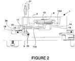
- Is an enlarged cross-section side view through the centre of the apparatus of
Figure 1 , with the stimulating and detecting means removed for clarity. - Figure 2A:
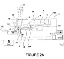
- Is the cross-section of
Figure 2 , with the net assembly removed for clarity. - Figure 3:
- Shows a front view of the well assembly of the apparatus of
Figure 1 in partial cross-section through the adjustable fluid level regulating means, and with a needle engaged with the fluid level regulation means. - Figure 4:
- Shows a perspective view of the well assembly and fluid level regulating means of the apparatus of
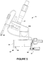
Figure 1 , with a needle engaged with the fluid level regulation means. - Figure 5:
- Shows a side view of the stimulating means of the apparatus of
Figure 1 . - Figure 6:
- Shows an exploded perspective view of a net assembly of the apparatus of
Figure 1 . - Figure 7:
- Shows an exploded cross-section of the net assembly of
Figure 6 . - Figure 8:
- Shows a side view of the stimulating means with an alternative electrode mounting means.
- Referring first to
Figures 1 ,2 and2A , theapparatus 100 of the present invention comprises abody 1 having achamber assembly 2 which is connected to or integral with abase 3. Thebase 3 is preferably substantially disc shaped. Awell 4 is formed within thechamber assembly 2, as is best seen inFigure 2A . - The
well 4 comprises acradle formation 5 for holding anet assembly 6 within which the tissue sample (not shown) is held. Thecradle formation 5 is preferably provided with a substantiallycylindrical recess 7. Theinner walls 7A of therecess 7 preferably taper slightly inwardly. - Stimulating means 8, for stimulating the tissue sample, and detecting
means 9, for detecting electrical activity in the tissue sample, are mounted to thebody 1. - A fluid inlet means 10 is provided though the
body 1 to allow a perfusion fluid to flow into thewell 4. The inlet means 10 comprises aconduit 11 provided with aninlet aperture 12 outside thewell 4 and anoutlet 13 beneath the cradle. Theoutlet 13 is formed into adiffuser portion 14 which expands outwardly in the direction of the fluid flow. Thediffuser portion 14 terminates directly below thecradle 5 and directs the fluid evenly through thenet assembly 6 and over the tissue sample. - The
inlet conduit 11 comprises a portion formed from an electrically conductive material such as astainless steel tube 11A. Thetube 11A is preferably both electrically conductive and thermally conductive, as is described further below. The electrically conductive material preferably has an electrical resistivity of less than 1 x 10⁻⁶ Ωm and a thermal conductivity of at least 10 W/mK. - In use, the perfusion fluid flows from a source (not shown) through the
inlet conduit 11. The fluid flows from theoutlet 13 of the inlet conduit, through thenet assembly 6 and over the tissue sample, and into aninner moat portion 15 of thewell 4. - An outlet means 16 comprises an upwardly
open port 17 provided in thebody 1. Theport 17 is in fluid communication with thewell 4, for example by means of anoutlet passage 18 provided in thebody 1 between the upwardlyopen port 17 and thewell 4. Thestainless steel tube 11A extends through a portion of theoutlet passage 18, so that thestainless steel tube 11A is fluid contact with the fluid flowing though theoutlet passage 18. - Because the
tube 11A is electrically conductive, it conducts any electrical charge from both the fluid stream flowing into theapparatus 100 through the inlet means 10, and the fluid stream flowing out of the apparatus though the outlet means 16. - The
tube 11A is in electrical contact with a common earth means. In a preferred embodiment the common earth means is an electrically conductiveannular member 19 which is electrically connected to thesteel tube 11A by means of agrounding screw 20. Thegrounding screw 20 preferably extends into theoutlet passage 18 so as to be in contact with the fluid in both theoutlet passage 18 and theinlet conduit 11A. - Referring next to
Figures 2 to 4 , and in particularFigure 3 , an adjustable fluid level regulation means 21 is provided to regulate the level of the fluid in thewell 4. The fluid regulation means 21 comprises anelongate member 22 connected to a suction inlet means 23. In a preferred embodiment the suction inlet means 23 comprises a fitting 24 adapted to releasably engage a disposable tube, for example aneedle 25. - The fluid regulation means 21 may be adapted to hold the
disposable needle 25 substantially parallel with longitudinal axis L-L of theelongate member 22. - The
elongate member 22 is mounted to a mountingaperture 26 in thebody 1 of the apparatus. In a preferred embodiment both theelongate member 22 and the mountingaperture 26 are substantially circular in transverse cross section. Theelongate member 22 is preferably provided with O-ring seals 27 to seal against the mountingaperture 26. - The mounting
aperture 26 is in fluid communication with anoutlet aperture 28 provided in thebody 1. - In use, a
needle 25 is mounted to the fitting 24. The vertical position of the fluid regulation means 21 relative to thebody 1 is adjusted by sliding theelongate member 22 up or down in the mountingaperture 26 as required. The position is adjusted until thetip 29 of theneedle 25 is at the level required of the fluid in thewell 4. - The fluid level regulation means 21 is preferably held in position by the friction between the O-
ring seals 27 and the mountingaperture 26, but suitable locking means (not shown) may additionally or alternatively be used. - When a vacuum is applied to the
outlet aperture 28, fluid is drawn out of the upwardlyopen port 17 by theneedle 25. The rate at which the fluid can be removed from the well 4 by the vacuum exceeds the rate at which the fluid is supplied though the inlet means 10. In this way the level of fluid in thewell 4 is maintained at the level of thetip 29 of theneedle 25. - Referring back to
Figure 2 , thechamber assembly 2 is also provided with anouter moat portion 15A. Theouter moat portion 15A may be used to accumulate the perfusion fluid when a vacuum source is not available. The fluid may be transferred from theinner moat 15 to theouter moat 15A by the use of suitable wicking material (not shown). Theouter moat portion 15A may be provided with a drain aperture (not shown) to allow it to drain. - Referring next to
Figures 1 and5 , the stimulating and detectingmeans electrode 30 engaged with a mounting means, generally referenced byarrow 200. The mounting means comprises amicromanipulator mechanism 31. - The mounting means 200 comprises gripping means 32 adapted to engage the
body 1. Thebody 1 is shaped so that gripping means 32 provided at thebase 33 of the mounting means 200 can engage with an inner surface 34 (best seen inFigure 2 ) of the electrically conductiveannular member 19, and with anouter surface 35 of thebase 3. The gripping means 32 comprises an electrically conductive grippingmember 36 which engages with theinner surface 34 of the electrically conductiveannular member 19. The electrically conductive grippingmember 36 is connected to a suitable terminal to allow electrical connection to the data recording system. - In a preferred embodiment the electrically conductive
annular member 19 is coaxial with the disc shapedbase 3. The electrically conductive grippingmember 36 of the grippingmeans 32 is a flange, and the outer part of the grippingmeans 32 is ascrew 37 which can be tightened onto theouter surface 35 of thebase 3. In a preferred embodiment thescrew 37 has a pointedhead 38, and theouter surface 35 of the base is provided with acircumferential groove 39 into which the pointed head seats. In this way, the stimulating and detectingmeans base 3, while maintaining the contact to thecommon earth 19. The quality of the contact between the conductive grippingmember 36 and theearth 19 is increased as the gripping or clamping force is increased. - As shown in
Figure 2 , thenet assembly 6 sits snugly inside thecradle formation 5. An O-ring (not shown) may be provided to create a seal between the outside of thenet assembly 6 and thetapering wall 7A of thecradle formation 5. - Referring next to
Figures 6 and7 , thenet assembly 6 comprises a first net means 40 which is nestable inside a second net means 41. - The first net means 40 comprises a substantially
annular frame 42 with a substantially frusto-conicalinner surface 43 and a substantially cylindricalouter surface 44. Aflange 45 is provided around the upper circumference of the first net, theflange 45 provided with a plurality oftab formations 46 protruding radially outward. An O-ring seal 47 is engaged with asuitable groove 48 in theouter surface 44 of the first net, and provides a suitable friction force between the first andsecond nets Suitable netting material 49 is provided at the opposite end of the frame from theflange 45. - The second net means 41 is provided with a substantially
annular frame 50 which has substantially cylindrical inner andouter surfaces flange 53 havingtab formations 54 which protrude radially outward. In a preferred embodiment the tab formations of bothnets tabs 46 from the number oftabs 54 on the second net 41, in order to avoid thetabs nets suitable netting material 55 at the opposite end of the frame to theflange 53. Types of suitable netting material for the first and second nets will be known to those skilled in the art. - In some embodiments a second O-ring (not shown) may be provided around the exterior of the second net means 41, in order to grip the inner walls of the
cradle formation 5. - Those skilled in the art will appreciate that the frusto-conical shape of the
inner surface 43 of the first net 40 reduces or substantially eliminates the "dead" area of the first net 40, that is, the area which is inaccessible by the stimulating and recording means 8, 9. - The
nets - Referring next to
Figure 8 , a stimulatingmeans 8 is shown with an alternative electrode mounting means, generally referenced 201, to that shown inFigure 5 . - In the embodiment shown in
Figure 8 the electrode mounting means 201 comprises a micromanipulator means 31 and grippingmeans 32 which are the same as those provided in the embodiment shown inFigure 5 . However, the electrode mounting means 201 is provided with an electrode engaging means 56 which comprises asheath 57. Thesheath 57 is preferably formed from a hollow tube, typically made from steel or the like. - A first end of the
sheath 57 is provided with achuck 58. Thechuck 58 is preferably of the collet chuck type, although other chucks may be suitable. The collet is preferably integral with thesheath 57. - The
chuck 58 is adapted to releasably grip theelectrode 30 in an "in use" position, as shown inFigure 8 . - The
sheath 57 is shaped and dimensioned to allow theelectrode 30 to be retracted inside thesheath 57 when not in use. In this way theelectrode 30 can be protected when theapparatus 100 is not in use and/or when the electrode mounting means 201 is being engaged or disengaged from theapparatus 100. - The distal end of the
sheath 57 is preferably also provided with asecond chuck 59 which can engage thecable 60 which carries the signal to or from theelectrode 30. Thesecond chuck 60 is preferably also of the collet chuck type. The electrode mounting means 201 may also be used with the detecting means. - Those skilled in the art will appreciate that the present invention provides an apparatus for testing electrical activity from a biological tissue sample which is relatively simple and portable, but which may be more reliable than comparable apparatus of the prior art.
- Unless the context clearly requires otherwise, throughout the description and the claims, the words "comprise", "comprising", and the like, are to be construed in an inclusive sense as opposed to an exclusive or exhaustive sense, that is to say, in the sense of "including, but not limited to".
Claims (10)
- An apparatus for testing electrical activity from a biological tissue sample, the apparatus (100) comprising a body (1) provided with a well (4), the apparatus (100) further comprising stimulating means (8) for stimulating a biological tissue sample which is located, in use, in the well (4), and detecting means (9) for detecting electrical activity in the biological tissue sample, the apparatus (100) further comprising a fluid inlet means (10) in fluid communication with the well (4) and a fluid outlet means (16) in fluid communication with the well (4), the fluid inlet means (10) comprising an electrically conductive conduit (11), characterised in that the fluid outlet means (16) comprises an outlet passage (18) provided in the body (1), and the electrically conductive conduit (11) of the fluid inlet means (10) extends through a portion of the outlet passage (18) and is in fluid contact with a fluid flowing, in use, through the outlet passage (18).
- The apparatus of claim 1 characterised in that the body (1) is provided with an electrically conductive member (19) which is electrically connectable to the electrically conductive conduit (11).
- The apparatus of claim 1or 2 characterised in that the electrically conductive conduit (11) has an electrical resistivity of less than 1 x 10⁻⁶ Ωm at room temperature.
- The apparatus of any one of the preceding claims characterised in that the electrically conductive conduit (11) has a thermal conductivity of at least 10 W/m K at room temperature.
- The apparatus of claim 4 characterised in that the fluid outlet means (16) comprises a passage adapted to receive a heating element such that the heating element is in thermal contact with fluid flowing, in use, through the outlet passage (18) upstream of the electrically conductive conduit (11), to thereby transfer heat to the fluid in the inlet means (10) through the electrically conductive conduit (11).
- The apparatus of claim 1, characterised in that the apparatus (100)
further comprises an electrically conductive member (19) in electrical contact with the fluid contained, in use, in at least one of the well (4), the fluid inlet means (10) and the fluid outlet means (16), wherein at least one of the stimulating means (8) and detecting means (9) is engaged with the body (1) by a gripping means (32) which comprises an electrically conductive gripping member (36) which engages the electrically conductive member (19), and the electrically conductive gripping member (36) is electrically connectable to a data recording system which, in use, is adapted to record the electrical activity from the biological tissue sample. - The apparatus of claim 6 characterised in that the electrically conductive member (19) comprises an annular ring.
- The apparatus of claim 7 characterised in that the annular ring is set into the body (1).
- The apparatus of claim 7 or 8 characterised in that the electrically conductive gripping member (36) exerts a force on an inner surface of the annular ring in a radially outward direction.
- The apparatus of claim 1 characterised in that the fluid outlet means (16) comprises an upwardly open outlet port (17) in fluid communication with the well (4) and an outlet aperture (28) which is fixed in position relative to the body (1), and the apparatus (100) further comprises an adjustable fluid level regulation means (21) adapted to draw fluid, in use, from the upwardly open outlet port (17) at a required level.
Applications Claiming Priority (2)
| Application Number | Priority Date | Filing Date | Title |
|---|---|---|---|
| US11404208P | 2008-11-12 | 2008-11-12 | |
| PCT/NZ2009/000250 WO2010056136A1 (en) | 2008-11-12 | 2009-11-12 | Apparatus for testing electrical activity from a biological tissue sample |
Publications (3)
| Publication Number | Publication Date |
|---|---|
| EP2356438A1 EP2356438A1 (en) | 2011-08-17 |
| EP2356438A4 EP2356438A4 (en) | 2017-04-19 |
| EP2356438B1 true EP2356438B1 (en) | 2018-04-11 |
Family
ID=42170128
Family Applications (1)
| Application Number | Title | Priority Date | Filing Date |
|---|---|---|---|
| EP09826347.8A Active EP2356438B1 (en) | 2008-11-12 | 2009-11-12 | Apparatus for testing electrical activity from a biological tissue sample |
Country Status (8)
| Country | Link |
|---|---|
| US (1) | US9103815B2 (en) |
| EP (1) | EP2356438B1 (en) |
| JP (1) | JP5877413B2 (en) |
| CN (1) | CN102224415B (en) |
| AU (1) | AU2009314696B2 (en) |
| ES (1) | ES2673008T3 (en) |
| NZ (1) | NZ593271A (en) |
| WO (1) | WO2010056136A1 (en) |
Families Citing this family (2)
| Publication number | Priority date | Publication date | Assignee | Title |
|---|---|---|---|---|
| CN102681551B (en) * | 2012-05-25 | 2014-06-18 | 华中科技大学 | Spatial three-dimensional azimuth fine-regulating device of rat brain embedding block |
| EP3097181B1 (en) | 2014-01-22 | 2020-07-01 | Molecular Devices, LLC | Replaceable ground electrode for electrophysiology |
Family Cites Families (11)
| Publication number | Priority date | Publication date | Assignee | Title |
|---|---|---|---|---|
| US4762594A (en) * | 1987-01-29 | 1988-08-09 | Medtest Systems, Inc. | Apparatus and methods for sensing fluid components |
| WO1997017426A1 (en) * | 1995-11-08 | 1997-05-15 | Trustees Of Boston University | Cellular physiology workstations for automated data acquisition and perfusion control |
| DK0980523T3 (en) * | 1997-05-01 | 2007-04-30 | Sophion Bioscience As | Device for automatic electrode placement |
| EP1208240A4 (en) * | 1999-08-26 | 2006-10-04 | Univ Princeton | MICROFLUIDIC AND MACROFLUIDIC ELECTRONIC DEVICES FOR DETECTING CHANGES IN THE CAPACITY OF LIQUIDS AND METHOD FOR THEIR USE. |
| WO2001033207A1 (en) * | 1999-11-04 | 2001-05-10 | Advanced Sensor Technologies, Inc. | Microscopic multi-site sensor array with integrated control and analysis circuitry |
| GB9930719D0 (en) * | 1999-12-24 | 2000-02-16 | Central Research Lab Ltd | Apparatus for and method of making electrical measurements on an object in a m edium |
| US6773678B2 (en) * | 2000-03-20 | 2004-08-10 | Endress + Hauser Conducta Gesellschaft Fur Mess Und Regeltechnik Mbh + Co. | Mounting system and retractable sensor holder for analytical sensors |
| US7011939B2 (en) * | 2000-03-22 | 2006-03-14 | Abbott Laboratories | Apparatus and method for electrophysiological testing |
| CN100392384C (en) * | 2000-10-09 | 2008-06-04 | 清华大学 | Method and sample solution for separating entity molecules on a chip |
| US20050131463A1 (en) * | 2003-12-12 | 2005-06-16 | Fedorov Nikolai B. | Perfusion chamber for recording evoked and spontaneous electrical activity from submerged acute brain slices |
| CN100412539C (en) * | 2005-04-14 | 2008-08-20 | 张荣华 | Detection standardization experimental apparatus platform for high-temperature high-pressure chemical sensor |
-
2009
- 2009-11-12 ES ES09826347.8T patent/ES2673008T3/en active Active
- 2009-11-12 EP EP09826347.8A patent/EP2356438B1/en active Active
- 2009-11-12 AU AU2009314696A patent/AU2009314696B2/en not_active Ceased
- 2009-11-12 JP JP2011536274A patent/JP5877413B2/en active Active
- 2009-11-12 US US13/129,059 patent/US9103815B2/en active Active
- 2009-11-12 WO PCT/NZ2009/000250 patent/WO2010056136A1/en not_active Ceased
- 2009-11-12 CN CN200980144973.XA patent/CN102224415B/en active Active
- 2009-11-12 NZ NZ593271A patent/NZ593271A/en unknown
Non-Patent Citations (1)
| Title |
|---|
| FROST WHITE W ET AL: "A perfusion chamber for the study of CNS physiology and pharmacology in vitro", BRAIN RESEARCH, ELSEVIER, AMSTERDAM, NL, vol. 152, no. 3, 8 September 1978 (1978-09-08), pages 591 - 596, XP024261850, ISSN: 0006-8993, [retrieved on 19780908], DOI: 10.1016/0006-8993(78)91115-0 * |
Also Published As
| Publication number | Publication date |
|---|---|
| US9103815B2 (en) | 2015-08-11 |
| JP2012508878A (en) | 2012-04-12 |
| EP2356438A4 (en) | 2017-04-19 |
| US20110223651A1 (en) | 2011-09-15 |
| JP5877413B2 (en) | 2016-03-08 |
| AU2009314696A1 (en) | 2011-06-30 |
| ES2673008T3 (en) | 2018-06-19 |
| CN102224415A (en) | 2011-10-19 |
| CN102224415B (en) | 2014-10-15 |
| AU2009314696B2 (en) | 2015-03-19 |
| NZ593271A (en) | 2014-03-28 |
| WO2010056136A1 (en) | 2010-05-20 |
| EP2356438A1 (en) | 2011-08-17 |
Similar Documents
| Publication | Publication Date | Title |
|---|---|---|
| Nicolas et al. | High throughput transepithelial electrical resistance (TEER) measurements on perfused membrane-free epithelia | |
| US6541243B1 (en) | Perfusion chamber for electrophysiological testing of oocytes | |
| EP0765384B1 (en) | Device for the study of organotypic cultures and its uses in electrophysiology and biochemistry | |
| CN102879256B (en) | The apparatus and method of analyte are obtained from dry biologicfluid sample | |
| JP5881621B2 (en) | Multi-reactor box for dynamic cell culture | |
| US8263389B2 (en) | Perifusion device | |
| US20180163165A1 (en) | Devices, systems, and methods for targeted plating of materials in high-throughput culture plates | |
| EP2151491A2 (en) | Multichamber bioreactor with bidirectional perfusion integrated in a culture system for tissue engineering strategies | |
| US20110045582A1 (en) | Methods and apparatus for integrated cell handling and measurements | |
| Hascup et al. | Second-by-second measures of L-glutamate and other neurotransmitters using enzyme-based microelectrode arrays | |
| US10016453B2 (en) | In vitro bio-reactor circuit | |
| CN108531542B (en) | Automatic drug sensitivity test device for gram-negative bacteria and application method | |
| EP4264248B1 (en) | Systems, devices and methods for cell analysis using chemfet sensor arrays | |
| AU2009314696B2 (en) | Apparatus for testing electrical activity from a biological tissue sample | |
| JP2003528308A (en) | Apparatus and method for electrophysiological testing | |
| DE4417078C2 (en) | Device for microscoping biological cells | |
| US20080168847A1 (en) | Perifusion device | |
| CN208933384U (en) | a culture tube | |
| ATE463300T1 (en) | DEVICE FOR ANALYZING AN INTERACTION BETWEEN TARGET AND PROBE MOLECULES | |
| KR20070072533A (en) | Reduced aperture biological specimen collection and transfer device | |
| WO2024081794A2 (en) | Microtiter-plate-based high throughput perfusion bioreactor | |
| Pusic et al. | Modeling neural immune signaling of episodic and chronic migraine using spreading depression in vitro | |
| EP2420187A1 (en) | Individually adjustable multi-channel systems in vivo recording | |
| Jahnsen et al. | + Department of Neurological Sciences, University of Genoa, Genoa, Italy | |
| JPH072000Y2 (en) | Irrigation device |
Legal Events
| Date | Code | Title | Description |
|---|---|---|---|
| PUAI | Public reference made under article 153(3) epc to a published international application that has entered the european phase |
Free format text: ORIGINAL CODE: 0009012 |
|
| 17P | Request for examination filed |
Effective date: 20110609 |
|
| AK | Designated contracting states |
Kind code of ref document: A1 Designated state(s): AT BE BG CH CY CZ DE DK EE ES FI FR GB GR HR HU IE IS IT LI LT LU LV MC MK MT NL NO PL PT RO SE SI SK SM TR |
|
| DAX | Request for extension of the european patent (deleted) | ||
| REG | Reference to a national code |
Ref country code: DE Ref legal event code: R079 Ref document number: 602009051782 Country of ref document: DE Free format text: PREVIOUS MAIN CLASS: G01N0027600000 Ipc: G01N0033483000 |
|
| RA4 | Supplementary search report drawn up and despatched (corrected) |
Effective date: 20170322 |
|
| RIC1 | Information provided on ipc code assigned before grant |
Ipc: G01N 33/483 20060101AFI20170316BHEP |
|
| GRAP | Despatch of communication of intention to grant a patent |
Free format text: ORIGINAL CODE: EPIDOSNIGR1 |
|
| STAA | Information on the status of an ep patent application or granted ep patent |
Free format text: STATUS: GRANT OF PATENT IS INTENDED |
|
| INTG | Intention to grant announced |
Effective date: 20171103 |
|
| GRAS | Grant fee paid |
Free format text: ORIGINAL CODE: EPIDOSNIGR3 |
|
| GRAA | (expected) grant |
Free format text: ORIGINAL CODE: 0009210 |
|
| STAA | Information on the status of an ep patent application or granted ep patent |
Free format text: STATUS: THE PATENT HAS BEEN GRANTED |
|
| AK | Designated contracting states |
Kind code of ref document: B1 Designated state(s): AT BE BG CH CY CZ DE DK EE ES FI FR GB GR HR HU IE IS IT LI LT LU LV MC MK MT NL NO PL PT RO SE SI SK SM TR |
|
| REG | Reference to a national code |
Ref country code: GB Ref legal event code: FG4D |
|
| REG | Reference to a national code |
Ref country code: CH Ref legal event code: EP |
|
| REG | Reference to a national code |
Ref country code: AT Ref legal event code: REF Ref document number: 988593 Country of ref document: AT Kind code of ref document: T Effective date: 20180415 |
|
| REG | Reference to a national code |
Ref country code: IE Ref legal event code: FG4D |
|
| REG | Reference to a national code |
Ref country code: DE Ref legal event code: R096 Ref document number: 602009051782 Country of ref document: DE |
|
| REG | Reference to a national code |
Ref country code: CH Ref legal event code: NV Representative=s name: VOSSIUS AND PARTNER PATENTANWAELTE RECHTSANWAE, CH |
|
| REG | Reference to a national code |
Ref country code: ES Ref legal event code: FG2A Ref document number: 2673008 Country of ref document: ES Kind code of ref document: T3 Effective date: 20180619 |
|
| REG | Reference to a national code |
Ref country code: NL Ref legal event code: MP Effective date: 20180411 |
|
| REG | Reference to a national code |
Ref country code: LT Ref legal event code: MG4D |
|
| PG25 | Lapsed in a contracting state [announced via postgrant information from national office to epo] |
Ref country code: NL Free format text: LAPSE BECAUSE OF FAILURE TO SUBMIT A TRANSLATION OF THE DESCRIPTION OR TO PAY THE FEE WITHIN THE PRESCRIBED TIME-LIMIT Effective date: 20180411 |
|
| PG25 | Lapsed in a contracting state [announced via postgrant information from national office to epo] |
Ref country code: LT Free format text: LAPSE BECAUSE OF FAILURE TO SUBMIT A TRANSLATION OF THE DESCRIPTION OR TO PAY THE FEE WITHIN THE PRESCRIBED TIME-LIMIT Effective date: 20180411 Ref country code: PL Free format text: LAPSE BECAUSE OF FAILURE TO SUBMIT A TRANSLATION OF THE DESCRIPTION OR TO PAY THE FEE WITHIN THE PRESCRIBED TIME-LIMIT Effective date: 20180411 Ref country code: SE Free format text: LAPSE BECAUSE OF FAILURE TO SUBMIT A TRANSLATION OF THE DESCRIPTION OR TO PAY THE FEE WITHIN THE PRESCRIBED TIME-LIMIT Effective date: 20180411 Ref country code: BG Free format text: LAPSE BECAUSE OF FAILURE TO SUBMIT A TRANSLATION OF THE DESCRIPTION OR TO PAY THE FEE WITHIN THE PRESCRIBED TIME-LIMIT Effective date: 20180711 Ref country code: NO Free format text: LAPSE BECAUSE OF FAILURE TO SUBMIT A TRANSLATION OF THE DESCRIPTION OR TO PAY THE FEE WITHIN THE PRESCRIBED TIME-LIMIT Effective date: 20180711 Ref country code: FI Free format text: LAPSE BECAUSE OF FAILURE TO SUBMIT A TRANSLATION OF THE DESCRIPTION OR TO PAY THE FEE WITHIN THE PRESCRIBED TIME-LIMIT Effective date: 20180411 |
|
| PG25 | Lapsed in a contracting state [announced via postgrant information from national office to epo] |
Ref country code: LV Free format text: LAPSE BECAUSE OF FAILURE TO SUBMIT A TRANSLATION OF THE DESCRIPTION OR TO PAY THE FEE WITHIN THE PRESCRIBED TIME-LIMIT Effective date: 20180411 Ref country code: HR Free format text: LAPSE BECAUSE OF FAILURE TO SUBMIT A TRANSLATION OF THE DESCRIPTION OR TO PAY THE FEE WITHIN THE PRESCRIBED TIME-LIMIT Effective date: 20180411 Ref country code: GR Free format text: LAPSE BECAUSE OF FAILURE TO SUBMIT A TRANSLATION OF THE DESCRIPTION OR TO PAY THE FEE WITHIN THE PRESCRIBED TIME-LIMIT Effective date: 20180712 |
|
| REG | Reference to a national code |
Ref country code: AT Ref legal event code: MK05 Ref document number: 988593 Country of ref document: AT Kind code of ref document: T Effective date: 20180411 |
|
| PG25 | Lapsed in a contracting state [announced via postgrant information from national office to epo] |
Ref country code: PT Free format text: LAPSE BECAUSE OF FAILURE TO SUBMIT A TRANSLATION OF THE DESCRIPTION OR TO PAY THE FEE WITHIN THE PRESCRIBED TIME-LIMIT Effective date: 20180813 |
|
| REG | Reference to a national code |
Ref country code: DE Ref legal event code: R097 Ref document number: 602009051782 Country of ref document: DE |
|
| PG25 | Lapsed in a contracting state [announced via postgrant information from national office to epo] |
Ref country code: AT Free format text: LAPSE BECAUSE OF FAILURE TO SUBMIT A TRANSLATION OF THE DESCRIPTION OR TO PAY THE FEE WITHIN THE PRESCRIBED TIME-LIMIT Effective date: 20180411 Ref country code: DK Free format text: LAPSE BECAUSE OF FAILURE TO SUBMIT A TRANSLATION OF THE DESCRIPTION OR TO PAY THE FEE WITHIN THE PRESCRIBED TIME-LIMIT Effective date: 20180411 Ref country code: SK Free format text: LAPSE BECAUSE OF FAILURE TO SUBMIT A TRANSLATION OF THE DESCRIPTION OR TO PAY THE FEE WITHIN THE PRESCRIBED TIME-LIMIT Effective date: 20180411 Ref country code: RO Free format text: LAPSE BECAUSE OF FAILURE TO SUBMIT A TRANSLATION OF THE DESCRIPTION OR TO PAY THE FEE WITHIN THE PRESCRIBED TIME-LIMIT Effective date: 20180411 Ref country code: CZ Free format text: LAPSE BECAUSE OF FAILURE TO SUBMIT A TRANSLATION OF THE DESCRIPTION OR TO PAY THE FEE WITHIN THE PRESCRIBED TIME-LIMIT Effective date: 20180411 Ref country code: EE Free format text: LAPSE BECAUSE OF FAILURE TO SUBMIT A TRANSLATION OF THE DESCRIPTION OR TO PAY THE FEE WITHIN THE PRESCRIBED TIME-LIMIT Effective date: 20180411 |
|
| PLBE | No opposition filed within time limit |
Free format text: ORIGINAL CODE: 0009261 |
|
| STAA | Information on the status of an ep patent application or granted ep patent |
Free format text: STATUS: NO OPPOSITION FILED WITHIN TIME LIMIT |
|
| PG25 | Lapsed in a contracting state [announced via postgrant information from national office to epo] |
Ref country code: SM Free format text: LAPSE BECAUSE OF FAILURE TO SUBMIT A TRANSLATION OF THE DESCRIPTION OR TO PAY THE FEE WITHIN THE PRESCRIBED TIME-LIMIT Effective date: 20180411 |
|
| 26N | No opposition filed |
Effective date: 20190114 |
|
| PG25 | Lapsed in a contracting state [announced via postgrant information from national office to epo] |
Ref country code: SI Free format text: LAPSE BECAUSE OF FAILURE TO SUBMIT A TRANSLATION OF THE DESCRIPTION OR TO PAY THE FEE WITHIN THE PRESCRIBED TIME-LIMIT Effective date: 20180411 |
|
| PG25 | Lapsed in a contracting state [announced via postgrant information from national office to epo] |
Ref country code: LU Free format text: LAPSE BECAUSE OF NON-PAYMENT OF DUE FEES Effective date: 20181112 Ref country code: MC Free format text: LAPSE BECAUSE OF FAILURE TO SUBMIT A TRANSLATION OF THE DESCRIPTION OR TO PAY THE FEE WITHIN THE PRESCRIBED TIME-LIMIT Effective date: 20180411 |
|
| REG | Reference to a national code |
Ref country code: BE Ref legal event code: MM Effective date: 20181130 |
|
| PG25 | Lapsed in a contracting state [announced via postgrant information from national office to epo] |
Ref country code: BE Free format text: LAPSE BECAUSE OF NON-PAYMENT OF DUE FEES Effective date: 20181130 |
|
| PG25 | Lapsed in a contracting state [announced via postgrant information from national office to epo] |
Ref country code: MT Free format text: LAPSE BECAUSE OF NON-PAYMENT OF DUE FEES Effective date: 20181112 |
|
| PG25 | Lapsed in a contracting state [announced via postgrant information from national office to epo] |
Ref country code: TR Free format text: LAPSE BECAUSE OF FAILURE TO SUBMIT A TRANSLATION OF THE DESCRIPTION OR TO PAY THE FEE WITHIN THE PRESCRIBED TIME-LIMIT Effective date: 20180411 |
|
| PG25 | Lapsed in a contracting state [announced via postgrant information from national office to epo] |
Ref country code: HU Free format text: LAPSE BECAUSE OF FAILURE TO SUBMIT A TRANSLATION OF THE DESCRIPTION OR TO PAY THE FEE WITHIN THE PRESCRIBED TIME-LIMIT; INVALID AB INITIO Effective date: 20091112 Ref country code: MK Free format text: LAPSE BECAUSE OF NON-PAYMENT OF DUE FEES Effective date: 20180411 Ref country code: CY Free format text: LAPSE BECAUSE OF FAILURE TO SUBMIT A TRANSLATION OF THE DESCRIPTION OR TO PAY THE FEE WITHIN THE PRESCRIBED TIME-LIMIT Effective date: 20180411 |
|
| PG25 | Lapsed in a contracting state [announced via postgrant information from national office to epo] |
Ref country code: IS Free format text: LAPSE BECAUSE OF FAILURE TO SUBMIT A TRANSLATION OF THE DESCRIPTION OR TO PAY THE FEE WITHIN THE PRESCRIBED TIME-LIMIT Effective date: 20180811 |
|
| PGFP | Annual fee paid to national office [announced via postgrant information from national office to epo] |
Ref country code: IE Payment date: 20211129 Year of fee payment: 13 |
|
| PGFP | Annual fee paid to national office [announced via postgrant information from national office to epo] |
Ref country code: IT Payment date: 20211122 Year of fee payment: 13 |
|
| PGFP | Annual fee paid to national office [announced via postgrant information from national office to epo] |
Ref country code: FR Payment date: 20221123 Year of fee payment: 14 Ref country code: ES Payment date: 20221201 Year of fee payment: 14 |
|
| PGFP | Annual fee paid to national office [announced via postgrant information from national office to epo] |
Ref country code: CH Payment date: 20221205 Year of fee payment: 14 |
|
| P01 | Opt-out of the competence of the unified patent court (upc) registered |
Effective date: 20230522 |
|
| PG25 | Lapsed in a contracting state [announced via postgrant information from national office to epo] |
Ref country code: IT Free format text: LAPSE BECAUSE OF NON-PAYMENT OF DUE FEES Effective date: 20221112 Ref country code: IE Free format text: LAPSE BECAUSE OF NON-PAYMENT OF DUE FEES Effective date: 20221112 |
|
| REG | Reference to a national code |
Ref country code: CH Ref legal event code: PL |
|
| PG25 | Lapsed in a contracting state [announced via postgrant information from national office to epo] |
Ref country code: CH Free format text: LAPSE BECAUSE OF NON-PAYMENT OF DUE FEES Effective date: 20231130 |
|
| PG25 | Lapsed in a contracting state [announced via postgrant information from national office to epo] |
Ref country code: CH Free format text: LAPSE BECAUSE OF NON-PAYMENT OF DUE FEES Effective date: 20231130 |
|
| PG25 | Lapsed in a contracting state [announced via postgrant information from national office to epo] |
Ref country code: FR Free format text: LAPSE BECAUSE OF NON-PAYMENT OF DUE FEES Effective date: 20231130 |
|
| PG25 | Lapsed in a contracting state [announced via postgrant information from national office to epo] |
Ref country code: FR Free format text: LAPSE BECAUSE OF NON-PAYMENT OF DUE FEES Effective date: 20231130 |
|
| REG | Reference to a national code |
Ref country code: ES Ref legal event code: FD2A Effective date: 20250102 |
|
| PGFP | Annual fee paid to national office [announced via postgrant information from national office to epo] |
Ref country code: DE Payment date: 20241127 Year of fee payment: 16 |
|
| PGFP | Annual fee paid to national office [announced via postgrant information from national office to epo] |
Ref country code: GB Payment date: 20241127 Year of fee payment: 16 |
|
| PG25 | Lapsed in a contracting state [announced via postgrant information from national office to epo] |
Ref country code: ES Free format text: LAPSE BECAUSE OF NON-PAYMENT OF DUE FEES Effective date: 20231113 |
|
| PG25 | Lapsed in a contracting state [announced via postgrant information from national office to epo] |
Ref country code: ES Free format text: LAPSE BECAUSE OF NON-PAYMENT OF DUE FEES Effective date: 20231113 |