EP2355915B1 - Method for selective removal of large particles from particle slurries - Google Patents
Method for selective removal of large particles from particle slurries Download PDFInfo
- Publication number
- EP2355915B1 EP2355915B1 EP09768579.6A EP09768579A EP2355915B1 EP 2355915 B1 EP2355915 B1 EP 2355915B1 EP 09768579 A EP09768579 A EP 09768579A EP 2355915 B1 EP2355915 B1 EP 2355915B1
- Authority
- EP
- European Patent Office
- Prior art keywords
- fabric
- slurry
- particles
- less
- media
- Prior art date
- Legal status (The legal status is an assumption and is not a legal conclusion. Google has not performed a legal analysis and makes no representation as to the accuracy of the status listed.)
- Active
Links
- 239000002245 particle Substances 0.000 title claims description 82
- 239000002002 slurry Substances 0.000 title claims description 56
- 238000000034 method Methods 0.000 title claims description 35
- 239000004744 fabric Substances 0.000 claims description 51
- 239000000835 fiber Substances 0.000 claims description 32
- 238000001914 filtration Methods 0.000 claims description 25
- 230000008569 process Effects 0.000 claims description 14
- 239000000463 material Substances 0.000 claims description 12
- 238000003490 calendering Methods 0.000 claims description 8
- 238000001523 electrospinning Methods 0.000 claims description 7
- 239000000203 mixture Substances 0.000 claims description 7
- 239000011148 porous material Substances 0.000 claims description 7
- 238000009826 distribution Methods 0.000 claims description 4
- 239000012530 fluid Substances 0.000 claims description 4
- 229910044991 metal oxide Inorganic materials 0.000 claims description 4
- 230000000717 retained effect Effects 0.000 claims description 4
- 238000007664 blowing Methods 0.000 claims description 3
- 239000000919 ceramic Substances 0.000 claims description 3
- 239000002184 metal Substances 0.000 claims description 3
- 229920000642 polymer Polymers 0.000 description 13
- 239000007787 solid Substances 0.000 description 13
- 239000002121 nanofiber Substances 0.000 description 11
- 238000005498 polishing Methods 0.000 description 9
- 239000012528 membrane Substances 0.000 description 8
- 230000014759 maintenance of location Effects 0.000 description 7
- 239000000758 substrate Substances 0.000 description 6
- 238000002844 melting Methods 0.000 description 5
- 230000008018 melting Effects 0.000 description 5
- 239000004014 plasticizer Substances 0.000 description 5
- 239000000243 solution Substances 0.000 description 5
- 230000015572 biosynthetic process Effects 0.000 description 4
- 238000010276 construction Methods 0.000 description 4
- -1 polyethylene Polymers 0.000 description 4
- 239000004952 Polyamide Substances 0.000 description 3
- 230000009471 action Effects 0.000 description 3
- 230000000052 comparative effect Effects 0.000 description 3
- 230000007547 defect Effects 0.000 description 3
- 239000007788 liquid Substances 0.000 description 3
- 229920001778 nylon Polymers 0.000 description 3
- 229920002647 polyamide Polymers 0.000 description 3
- 239000004065 semiconductor Substances 0.000 description 3
- XLYOFNOQVPJJNP-UHFFFAOYSA-N water Substances O XLYOFNOQVPJJNP-UHFFFAOYSA-N 0.000 description 3
- UQSXHKLRYXJYBZ-UHFFFAOYSA-N Iron oxide Chemical compound [Fe]=O UQSXHKLRYXJYBZ-UHFFFAOYSA-N 0.000 description 2
- 229920002302 Nylon 6,6 Polymers 0.000 description 2
- 239000004793 Polystyrene Substances 0.000 description 2
- 239000004372 Polyvinyl alcohol Substances 0.000 description 2
- 229910052581 Si3N4 Inorganic materials 0.000 description 2
- 229910000831 Steel Inorganic materials 0.000 description 2
- 238000005054 agglomeration Methods 0.000 description 2
- 230000002776 aggregation Effects 0.000 description 2
- PNEYBMLMFCGWSK-UHFFFAOYSA-N aluminium oxide Inorganic materials [O-2].[O-2].[O-2].[Al+3].[Al+3] PNEYBMLMFCGWSK-UHFFFAOYSA-N 0.000 description 2
- CETPSERCERDGAM-UHFFFAOYSA-N ceric oxide Chemical compound O=[Ce]=O CETPSERCERDGAM-UHFFFAOYSA-N 0.000 description 2
- 229910000422 cerium(IV) oxide Inorganic materials 0.000 description 2
- 239000003795 chemical substances by application Substances 0.000 description 2
- 238000009833 condensation Methods 0.000 description 2
- 230000005494 condensation Effects 0.000 description 2
- 230000003247 decreasing effect Effects 0.000 description 2
- DOIRQSBPFJWKBE-UHFFFAOYSA-N dibutyl phthalate Chemical compound CCCCOC(=O)C1=CC=CC=C1C(=O)OCCCC DOIRQSBPFJWKBE-UHFFFAOYSA-N 0.000 description 2
- 238000004455 differential thermal analysis Methods 0.000 description 2
- 230000001747 exhibiting effect Effects 0.000 description 2
- 238000004519 manufacturing process Methods 0.000 description 2
- 238000005259 measurement Methods 0.000 description 2
- BDAGIHXWWSANSR-UHFFFAOYSA-N methanoic acid Natural products OC=O BDAGIHXWWSANSR-UHFFFAOYSA-N 0.000 description 2
- 239000012071 phase Substances 0.000 description 2
- XNGIFLGASWRNHJ-UHFFFAOYSA-L phthalate(2-) Chemical compound [O-]C(=O)C1=CC=CC=C1C([O-])=O XNGIFLGASWRNHJ-UHFFFAOYSA-L 0.000 description 2
- 229920003229 poly(methyl methacrylate) Polymers 0.000 description 2
- 229920002492 poly(sulfone) Polymers 0.000 description 2
- 229920000728 polyester Polymers 0.000 description 2
- 239000002861 polymer material Substances 0.000 description 2
- 239000004926 polymethyl methacrylate Substances 0.000 description 2
- 229920000098 polyolefin Polymers 0.000 description 2
- 229920002223 polystyrene Polymers 0.000 description 2
- 229920002451 polyvinyl alcohol Polymers 0.000 description 2
- 235000019422 polyvinyl alcohol Nutrition 0.000 description 2
- 239000004800 polyvinyl chloride Substances 0.000 description 2
- 229920000915 polyvinyl chloride Polymers 0.000 description 2
- 229920002981 polyvinylidene fluoride Polymers 0.000 description 2
- 239000011347 resin Substances 0.000 description 2
- 229920005989 resin Polymers 0.000 description 2
- 150000003839 salts Chemical class 0.000 description 2
- HQVNEWCFYHHQES-UHFFFAOYSA-N silicon nitride Chemical compound N12[Si]34N5[Si]62N3[Si]51N64 HQVNEWCFYHHQES-UHFFFAOYSA-N 0.000 description 2
- 239000002904 solvent Substances 0.000 description 2
- 238000009987 spinning Methods 0.000 description 2
- 239000010959 steel Substances 0.000 description 2
- 238000003860 storage Methods 0.000 description 2
- 239000000126 substance Substances 0.000 description 2
- 229920001169 thermoplastic Polymers 0.000 description 2
- 238000012876 topography Methods 0.000 description 2
- OSWFIVFLDKOXQC-UHFFFAOYSA-N 4-(3-methoxyphenyl)aniline Chemical compound COC1=CC=CC(C=2C=CC(N)=CC=2)=C1 OSWFIVFLDKOXQC-UHFFFAOYSA-N 0.000 description 1
- 239000004925 Acrylic resin Substances 0.000 description 1
- 229920000178 Acrylic resin Polymers 0.000 description 1
- 229920003043 Cellulose fiber Polymers 0.000 description 1
- RYGMFSIKBFXOCR-UHFFFAOYSA-N Copper Chemical compound [Cu] RYGMFSIKBFXOCR-UHFFFAOYSA-N 0.000 description 1
- 229920000742 Cotton Polymers 0.000 description 1
- MQIUGAXCHLFZKX-UHFFFAOYSA-N Di-n-octyl phthalate Natural products CCCCCCCCOC(=O)C1=CC=CC=C1C(=O)OCCCCCCCC MQIUGAXCHLFZKX-UHFFFAOYSA-N 0.000 description 1
- VOWAEIGWURALJQ-UHFFFAOYSA-N Dicyclohexyl phthalate Chemical compound C=1C=CC=C(C(=O)OC2CCCCC2)C=1C(=O)OC1CCCCC1 VOWAEIGWURALJQ-UHFFFAOYSA-N 0.000 description 1
- ZVFDTKUVRCTHQE-UHFFFAOYSA-N Diisodecyl phthalate Chemical compound CC(C)CCCCCCCOC(=O)C1=CC=CC=C1C(=O)OCCCCCCCC(C)C ZVFDTKUVRCTHQE-UHFFFAOYSA-N 0.000 description 1
- 239000004677 Nylon Substances 0.000 description 1
- 229920002292 Nylon 6 Polymers 0.000 description 1
- 229920000305 Nylon 6,10 Polymers 0.000 description 1
- 229920000577 Nylon 6/66 Polymers 0.000 description 1
- 239000002033 PVDF binder Substances 0.000 description 1
- 229930182556 Polyacetal Natural products 0.000 description 1
- 239000004698 Polyethylene Substances 0.000 description 1
- 239000004743 Polypropylene Substances 0.000 description 1
- 229920001328 Polyvinylidene chloride Polymers 0.000 description 1
- VYPSYNLAJGMNEJ-UHFFFAOYSA-N Silicium dioxide Chemical compound O=[Si]=O VYPSYNLAJGMNEJ-UHFFFAOYSA-N 0.000 description 1
- UCKMPCXJQFINFW-UHFFFAOYSA-N Sulphide Chemical compound [S-2] UCKMPCXJQFINFW-UHFFFAOYSA-N 0.000 description 1
- 230000002378 acidificating effect Effects 0.000 description 1
- 239000002671 adjuvant Substances 0.000 description 1
- 239000000956 alloy Substances 0.000 description 1
- 229910045601 alloy Inorganic materials 0.000 description 1
- 125000003118 aryl group Chemical group 0.000 description 1
- 230000000712 assembly Effects 0.000 description 1
- 238000000429 assembly Methods 0.000 description 1
- BJQHLKABXJIVAM-UHFFFAOYSA-N bis(2-ethylhexyl) phthalate Chemical compound CCCCC(CC)COC(=O)C1=CC=CC=C1C(=O)OCC(CC)CCCC BJQHLKABXJIVAM-UHFFFAOYSA-N 0.000 description 1
- 229920001400 block copolymer Polymers 0.000 description 1
- 239000000872 buffer Substances 0.000 description 1
- 239000002775 capsule Substances 0.000 description 1
- 229920002678 cellulose Polymers 0.000 description 1
- 229920003086 cellulose ether Polymers 0.000 description 1
- 239000013043 chemical agent Substances 0.000 description 1
- 238000003486 chemical etching Methods 0.000 description 1
- 238000004891 communication Methods 0.000 description 1
- 239000002131 composite material Substances 0.000 description 1
- 229920001577 copolymer Polymers 0.000 description 1
- 229910052802 copper Inorganic materials 0.000 description 1
- 239000010949 copper Substances 0.000 description 1
- 229910052593 corundum Inorganic materials 0.000 description 1
- 238000010790 dilution Methods 0.000 description 1
- 239000012895 dilution Substances 0.000 description 1
- DWNAQMUDCDVSLT-UHFFFAOYSA-N diphenyl phthalate Chemical compound C=1C=CC=C(C(=O)OC=2C=CC=CC=2)C=1C(=O)OC1=CC=CC=C1 DWNAQMUDCDVSLT-UHFFFAOYSA-N 0.000 description 1
- QQVHEQUEHCEAKS-UHFFFAOYSA-N diundecyl benzene-1,2-dicarboxylate Chemical compound CCCCCCCCCCCOC(=O)C1=CC=CC=C1C(=O)OCCCCCCCCCCC QQVHEQUEHCEAKS-UHFFFAOYSA-N 0.000 description 1
- 238000001035 drying Methods 0.000 description 1
- 238000005516 engineering process Methods 0.000 description 1
- 150000002148 esters Chemical class 0.000 description 1
- 238000005530 etching Methods 0.000 description 1
- 230000009969 flowable effect Effects 0.000 description 1
- 235000019253 formic acid Nutrition 0.000 description 1
- 239000003365 glass fiber Substances 0.000 description 1
- 230000009477 glass transition Effects 0.000 description 1
- 238000000227 grinding Methods 0.000 description 1
- 230000007062 hydrolysis Effects 0.000 description 1
- 238000006460 hydrolysis reaction Methods 0.000 description 1
- 239000011810 insulating material Substances 0.000 description 1
- JEIPFZHSYJVQDO-UHFFFAOYSA-N iron(III) oxide Inorganic materials O=[Fe]O[Fe]=O JEIPFZHSYJVQDO-UHFFFAOYSA-N 0.000 description 1
- 239000011159 matrix material Substances 0.000 description 1
- 230000007246 mechanism Effects 0.000 description 1
- 239000004750 melt-blown nonwoven Substances 0.000 description 1
- 229910052751 metal Inorganic materials 0.000 description 1
- 239000002923 metal particle Substances 0.000 description 1
- 238000002156 mixing Methods 0.000 description 1
- 239000002086 nanomaterial Substances 0.000 description 1
- 230000003287 optical effect Effects 0.000 description 1
- 239000007800 oxidant agent Substances 0.000 description 1
- XNGIFLGASWRNHJ-UHFFFAOYSA-N phthalic acid Chemical class OC(=O)C1=CC=CC=C1C(O)=O XNGIFLGASWRNHJ-UHFFFAOYSA-N 0.000 description 1
- 229920001281 polyalkylene Polymers 0.000 description 1
- 229920000412 polyarylene Polymers 0.000 description 1
- 229920001748 polybutylene Polymers 0.000 description 1
- 229920000573 polyethylene Polymers 0.000 description 1
- 229920000139 polyethylene terephthalate Polymers 0.000 description 1
- 239000005020 polyethylene terephthalate Substances 0.000 description 1
- 229920006324 polyoxymethylene Polymers 0.000 description 1
- 229920001155 polypropylene Polymers 0.000 description 1
- 230000002028 premature Effects 0.000 description 1
- 239000013557 residual solvent Substances 0.000 description 1
- 238000000926 separation method Methods 0.000 description 1
- HBMJWWWQQXIZIP-UHFFFAOYSA-N silicon carbide Chemical compound [Si+]#[C-] HBMJWWWQQXIZIP-UHFFFAOYSA-N 0.000 description 1
- 239000007779 soft material Substances 0.000 description 1
- 239000007790 solid phase Substances 0.000 description 1
- 238000003892 spreading Methods 0.000 description 1
- 230000007480 spreading Effects 0.000 description 1
- 239000000725 suspension Substances 0.000 description 1
- 229920005992 thermoplastic resin Polymers 0.000 description 1
- 239000004416 thermosoftening plastic Substances 0.000 description 1
- 230000007704 transition Effects 0.000 description 1
- 229910052723 transition metal Inorganic materials 0.000 description 1
- 150000003624 transition metals Chemical class 0.000 description 1
- WFKWXMTUELFFGS-UHFFFAOYSA-N tungsten Chemical compound [W] WFKWXMTUELFFGS-UHFFFAOYSA-N 0.000 description 1
- 229910052721 tungsten Inorganic materials 0.000 description 1
- 239000010937 tungsten Substances 0.000 description 1
- 230000037303 wrinkles Effects 0.000 description 1
- 229910001845 yogo sapphire Inorganic materials 0.000 description 1
Images
Classifications
-
- B—PERFORMING OPERATIONS; TRANSPORTING
- B01—PHYSICAL OR CHEMICAL PROCESSES OR APPARATUS IN GENERAL
- B01D—SEPARATION
- B01D39/00—Filtering material for liquid or gaseous fluids
- B01D39/14—Other self-supporting filtering material ; Other filtering material
- B01D39/16—Other self-supporting filtering material ; Other filtering material of organic material, e.g. synthetic fibres
- B01D39/1607—Other self-supporting filtering material ; Other filtering material of organic material, e.g. synthetic fibres the material being fibrous
- B01D39/1623—Other self-supporting filtering material ; Other filtering material of organic material, e.g. synthetic fibres the material being fibrous of synthetic origin
-
- B—PERFORMING OPERATIONS; TRANSPORTING
- B01—PHYSICAL OR CHEMICAL PROCESSES OR APPARATUS IN GENERAL
- B01D—SEPARATION
- B01D2239/00—Aspects relating to filtering material for liquid or gaseous fluids
- B01D2239/02—Types of fibres, filaments or particles, self-supporting or supported materials
- B01D2239/025—Types of fibres, filaments or particles, self-supporting or supported materials comprising nanofibres
-
- B—PERFORMING OPERATIONS; TRANSPORTING
- B01—PHYSICAL OR CHEMICAL PROCESSES OR APPARATUS IN GENERAL
- B01D—SEPARATION
- B01D2259/00—Type of treatment
- B01D2259/12—Methods and means for introducing reactants
- B01D2259/126—Semi-solid reactants, e.g. slurries
Definitions
- the present invention relates broadly to filters for separation of the large size fraction of particles from slurries comprising large and small particles, and in particular to chemical-mechanical polishing (CMP) slurries.
- CMP chemical-mechanical polishing
- circuit traces are photolithographically imaged over several layers on a single semiconducting wafer which, in turn, is cut into hundreds of identical dies or chips.
- the circuit traces are insulated from the next layer by an insulating material. It is desirable that the insulating layers are provided as having a smooth surface topography. In this regard, a relatively rough surface topography may result in poor coverage by subsequently deposited layers, and in the formation of voids between layers.
- any such defects become unacceptable and may render the circuit either inoperable or lower its performance to less than optimal.
- CMP chemical-mechanical polishing
- the aqueous slurry which may be either acidic or basic, typically includes abrasive particles; a reactive chemical agent such as a transition metal chelated salt or an oxidizer, and adjuvants such as solvents, buffers, and passivating agents.
- a reactive chemical agent such as a transition metal chelated salt or an oxidizer
- adjuvants such as solvents, buffers, and passivating agents.
- the salt or other agent provides the chemical etching action, with the abrasive particles, in cooperation with the polishing pad, providing the mechanical polishing action.
- Slurries for CMP which are further described in U.S. Pat. Nos. 5,516,346 ; 5,318,927 ; 5,264,010 ; 5,209,816 ; 4,954,142 , may be of either an oxide, i.e., ceramic, or metal abrasive particle type.
- Common oxide-type particles include silica (SiO 2 ) ceria (CeO 2 ), silicon carbide (SiC), silicon nitride (Si 3 N 4 ), iron oxide (Fe 2 O 3 ), alumina (Al 2 O 3 ), and the like, with common metal particles including tungsten and copper.
- the slurry can have a mean average abrasive particle size as low as between about 0.02-0.3 ⁇ m for oxide slurries.
- the CMP process stream can be filtered at the point of use to separate agglomerated particles of a size larger than a predetermined limit from the balance of the slurry.
- filters employing conventional membranes elements which may be of a phase inversion or bi-axially stretched variety generally having particle retention ratings between about 0.3-0.65 ⁇ m, were suggested.
- membranes filters of such type were observed to load almost instantaneously with particulate and soon were judged unacceptable for the CMP process.
- the characteristics of conventional membrane filter media are described in greater detail in U.S. Pat. Nos. 5,449,917 ; 4,863,604 ; 4,795,559 ; 4,791,144 ; 4,770,785 ; 4,728,394 ; and 3,852,134 .
- a fibrous media such as randomly orientated webs. Indeed, unlike membranes which rely on surface-type filtration, these fibrous media utilize a tortuous path, depth-type filtration mechanism.
- a fibrous media In order to provide increased service life, however, a fibrous media must be selected as having a relatively open and permeable structure rated, for example, at about 40-100 ⁇ m absolute or 5-30 ⁇ m nominal. Such a rating ensures substantially no retention of particles in the 0.5-2 ⁇ m range which could cause cake formation and, ultimately, premature blockage of the filter element. As a drawback, the more open and permeable structure does allow for some passage of large size particles which could damage the substrate being planarized.
- fibrous media in general characteristically exhibit a gradually decreasing retention profile as a function of decreasing particle size which is in contrast to the sharper particle size cutoff exhibited by membranes and other surface-type media.
- Depth-type and other filter media are described in further in U.S. Pat. Nos. 5,637,271 ; 5,225,014 ; 5,130,134 ; 4,225,642 ; and 4,025,679 .
- Document WO 02/089951 A1 discloses a method for removing the high particle size fraction of a slurry using a depth-type filter media.
- a filter element would be desirable exhibiting a particle retention profile which is comparable to surface filtering membranes, but with a service life which is more like that of a depth filtering media.
- a retention profile that passes particles of below around 0.1 micron in diameter but has a steep section to its particle size verses filtration efficiency curve that allows particles above about 0.5 microns to be removed efficiently.
- a method for removing the high particle size tail of the particle size distribution of a slurry while leaving smaller particles in the slurry comprising the steps of;
- the polymeric fibers form a nanoweb.
- the polymeric fibers of said fabric of step (i) have a number average fiber diameter of between 200 and 1000 nm, and more preferably between 150 and 600 nm.
- the polymeric fibers may optionally further be made by a process selected from the group consisting of electrospinning, electroblowing, spunbonding and melt blowing.
- the particles comprise a material selected from the group consisting of ceramic, metal or metallic oxide materials, or a mixture thereof.
- the thickness dimension of said fabric of step (i) may be between about 150-200 ⁇ m.
- said fabric of step (i) has been calendered effective to reduce the pore size of said fabric by about 20-50% less than a first pore size before calendering of said fabric.
- the pore size of said fabric of step (i) is between about 0.5 - 10 ⁇ m.
- the invention is also directed towards a method for removing the high particle size tail of the particle size distribution of a slurry while leaving smaller particles in the slurry comprising the steps of;
- nanofiber refers to fibers having a number average diameter or cross-section less than about 1000 nm, even less than about 800 nm, even between about 50 nm and 500 nm, and even between about 100 and 400 nm or even 150 and 600 nm.
- diameter as used herein includes the greatest cross-section of non-round shapes.
- nonwoven means a web including a multitude of randomly distributed fibers.
- the fibers generally can be bonded to each other or can be unbonded.
- the fibers can be staple fibers or continuous fibers.
- the fibers can comprise a single material or a multitude of materials, either as a combination of different fibers or as a combination of similar fibers each comprised of different materials.
- a "nanoweb” is a nonwoven web that comprises nanofibers.
- nanoweb as used herein is synonymous with the term “nanofiber web.”
- the filter media of the present invention is described in connection with its use as a filter element within a conventional cartridge filter assembly which may coupled in fluid communication with a chemical-mechanical polishing (CMP) slurry.
- CMP chemical-mechanical polishing
- Assemblies of such type and their construction are described further in commonly-assigned U.S. Pat. No. 5,154,827 , and elsewhere in U.S. Pat. Nos. 4,056,476 ; 4,104,170 ; 4,663,041 ; 5,154,827 ; and 5,543,047 .
- aspects of the present invention may find utility in other filter assembles such as capsules having integral media, housings, fittings, and the like. Use within those such other applications therefore should be considered to be expressly within the scope of the present invention.
- the present is directed towards a method for filtering large particles from a slurry comprising the step of passing the slurry through a filter medium that comprises a nanoweb.
- the method comprises the steps of;
- the largest number of particles will belong to the first set of particles, and these are typically less than 0.1 microns.
- the invention is not limited to this situation, however, and any arbitrary particle size distribution that conforms to the scope of the claims can be filtered by the method of the invention.
- the as-spun nanoweb comprises primarily or exclusively nanofibers, advantageously produced by electrospinning, such as classical electrospinning or electroblowing, and also, by meltblowing or other such suitable processes.
- electrospinning such as classical electrospinning or electroblowing
- meltblowing or other such suitable processes are particularly useful in the as-spun nanoweb.
- Classical electrospinning is a technique illustrated in U.S. Patent No. 4,127,706 , incorporated herein in its entirety, wherein a high voltage is applied to a polymer in solution to create nanofibers and nonwoven mats.
- total throughput in electrospinning processes is too low to be commercially viable in forming heavier basis weight webs.
- a stream of polymeric solution comprising a polymer and a solvent is fed from a storage tank to a series of spinning nozzles within a spinneret, to which a high voltage is applied and through which the polymeric solution is discharged. Meanwhile, compressed air that is optionally heated is issued from air nozzles disposed in the sides of, or at the periphery of the spinning nozzle. The air is directed generally downward as a blowing gas stream which envelopes and forwards the newly issued polymeric solution and aids in the formation of the fibrous web, which is collected on a grounded porous collection belt above a vacuum chamber.
- the electroblowing process permits formation of commercial sizes and quantities of nanowebs at basis weights in excess of about 1 gsm, even as high as about 40 gsm or greater, in a relatively short time period.
- a substrate or scrim can be arranged on the collector to collect and combine the nanofiber web spun on the substrate, so that the combined fiber web is used as a high-performance filter, wiper and so on.
- the substrate may include various nonwoven cloths, such as meltblown nonwoven cloth, needle-punched or spunlaced nonwoven cloth, woven cloth, knitted cloth, paper, and the like, and can be used without limitations so long as a nanofiber layer can be added on the substrate.
- the nonwoven cloth can comprise spunbond fibers, dry-laid or wet-laid fibers, cellulose fibers, melt blown fibers, glass fibers, or blends thereof.
- Polymer materials that can be used in forming the nanowebs of the invention are not particularly limited and include both addition polymer and condensation polymer materials such as, polyacetal, polyamide, polyester, polyolefins, cellulose ether and ester, polyalkylene sulfide, polyarylene oxide, polysulfone, modified polysulfone polymers, and mixtures thereof.
- Preferred materials that fall within these generic classes include, poly (vinylchloride), polymethylmethacrylate (and other acrylic resins), polystyrene, and copolymers thereof (including ABA type block copolymers), poly (vinylidene fluoride), poly (vinylidene chloride), polyvinylalcohol in various degrees of hydrolysis (87% to 99.5%) in crosslinked and non-crosslinked forms.
- Preferred addition polymers tend to be glassy (a Tg greater than room temperature). This is the case for polyvinylchloride and polymethylmethacrylate, polystyrene polymer compositions or alloys or low in crystallinity for polyvinylidene fluoride and polyvinylalcohol materials.
- polyamide condensation polymers are nylon materials, such as nylon-6, nylon-6, 6, nylon 6, 6-6, 10, and the like.
- any thermoplastic polymer capable of being meltblown into nanofibers can be used, including polyolefins, such as polyethylene, polypropylene and polybutylene, polyesters such as poly (ethylene terephthalate) and polyamides, such as the nylon polymers listed above.
- plasticizers can be added to the various polymers described above, in order to reduce the Tg of the fiber polymer.
- Suitable plasticizers will depend upon the polymer to be electrospun or electroblown, as well as upon the particular end use into which the nanoweb will be introduced.
- nylon polymers can be plasticized with water or even residual solvent remaining from the electrospinning or electroblowing process.
- the Handbook of Plasticizers edited by George Wypych, 2004 Chemtec Publishing, incorporated herein by reference, discloses other polymer/plasticizer combinations which can be used in the present invention.
- the retention profile of filter media of the present invention may be tailored for specific applications by optionally calendering the fabric sheet, such as by compressing between the heated, rotating rolls of a roll mill or the like.
- the rolls may be maintained at a temperature which is less than the melting point of the resin.
- Melting point is used herein in its broadest sense to include a temperature or temperature range evidencing in the material a transition from a form-stable crystalline or glassy solid phase to a flowable liquid, semi-liquid, or otherwise viscous phase or melt which may be generally characterized as exhibiting intermolecular chain rotation.
- the resins contemplated for the filter media of the present invention typically will exhibit a peak melting points of between about 150-280 °C as determined by means of differential scanning calorimeter (DSC) or differential thermal analysis (DTA).
- DSC differential scanning calorimeter
- DTA differential thermal analysis
- melting point is used interchangeably with glass transition or softening point.
- a filter media offering a unique convergence of properties is described which is especially adapted for use in CMP slurries.
- Such media unexpectedly exhibits a particle retention profile comparable to surface filtering membranes, but with a service life which is more like that of a depth filtering media.
- the invention is also directed to a method as described in any of the embodiments above and including the step of back pulsing the media.
- the media of the invention has the desirable characteristic that the pressure drop across the membrane can be reduced to very close to its original initial value at the beginning of filtration with the application of a very low back pressure.
- the method of the invention also optionally comprises the steps of stopping the flow of slurry through the fabric when the pressure drop across the fabric is 415 kPa, applying a fluid back pressure across the fabric in a direction opposite to that of the slurry flow in which the back pressure is less than about 3 kPa and lasts for less than 5 seconds and then resuming the flow of slurry through the fabric in the original direction.
- the pressure drop across the fabric after resuming the flow of slurry is no more than 25 % higher than it was when the flow commenced originally.
- Example 1 A 24% solution of polyamide-6,6 in formic acid was spun by electroblowing as described in WO 03/080905 .
- the number average fiber diameter for Example 1 was about 420 nm.
- the as-spun media in Example 1 was co-pleated between two scrims of spunbond media for support.
- the pleated media was converted to a standard 222 10" cartridge with approximately seven square feet of surface area of the media.
- the media for Example 2 was calendered from Example 1.
- the nanofiber sheets of Examples 1 were calendered by delivering the nanofiber sheets to a two roll calender nip from an unwind. A device for spreading the sheet prior to the nip was used to maintain a flat, wrinkle free sheet upon entering the nip.
- the hard roll was a 16.04 inch (40.74 cm) diameter steel roll
- the soft roll was a cotton-wool composite roll having a Shore D hardness of about 78, and about 20.67 inches (52.50 cm) in diameter.
- the media were calendered with the steel roll heated to 150°C and at line speed of 45 ft/min. Nip pressure is 916.2 PLI.
- the media was then co-pleated with two support scrims of spunbond media into a standard 222 10" filter cartridge.
- a comparative filter was tested.
- the filter was obtained from Pall Corporation (East Hills, NY) The Pall Corp.
- NXA series filters are manufactured using CoLD fiber meltblowing technology, which integrates Co-Located Large Diameter fibers within the fine fiber matrix to produce a rigid structural network to the cartridge.
- Syton® HT50 CMP slurry was obtained from DuPont Air Products Nanomaterials LLC (Tempe, AZ). 380 liters of 10% solids slurry was prepared in a tank by mixing the as-received 50% solids slurry with 0.1 micron filtered DI water. A sample of the slurry was collected for the unfiltered particle count and % solids measurement. The slurry was then filtered at a flow rate of 19 L/min utilizing a closed loop filtration system consisting of a storage tank, Levitronix LLC (Waltham, MA) BPS-4 centrifugal pump system, flowmeter, 10" filter housing containing a 10" filter cartridge and pressure sensors located immediately before and after the filter housing.
- a sample of the slurry was collected after 20 minutes (380 liters passed through filter) for particle count and % solids measurement and the filtration test was concluded.
- the unfiltered and filtered samples were measured for % solids using a Mettler Toledo (Columbus, OH) HR83P moisture analyzer.
- the unfiltered and filtered samples were measured for particle counts using Particle Measuring Systems Inc. (Boulder, CO) Liquilaz SO2 and Liquilaz SO5 liquid optical particle counters.
- the 10% solids slurry was diluted with 0.1 micron filtered DI water to a final concentration at the particle counting sensors of 0.000075% solids (a dilution factor of 133333.3).
- Filtration efficiency was calculated at a given particle size from the ratio of the particles number concentration passed by the medium to the particle concentration that impinged on the medium within a particle "bin" size corresponding to 0.01 microns. Overall efficiency was calculated from the weight percent solids passed by the medium divided by the weight percent solids impinging on the medium.
- Table 1 shows the solids contents of the samples filtered by the nanoweb construction and the comparative meltblown construction.
- the actual solids removed form the colloidal suspensions by the filers is low - of the order of 0.02%, corresponding to a filtration efficiency of around 0.2% only.
- TABLE 1 Solids Contents of Unfiltered and Filtered Samples Sample % Solids Unfiltered (pre Nanoweb) 9.69 Filtered (Nanoweb) 9.67 Unfiltered (pre meltblown) 9.72 Filtered (meltblown) 9.7
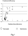
- Figure 1 shows the results of fractional filtration efficiency versus particle size for particles separated into 0.01 micron bins.
- meltblown and the nanoweb based filter have efficiencies of close to zero.
- the nanoweb based filter has a desirable steeper curve as particle size increases that is not obtainable with a meltblown based construction.
- Table 1 and figure 1 confirm the high filtration efficiency that the nanoweb sample has for the larger, undesired, particles, while still passing at least around 99.98% of the total particle count that predominantly consist of smaller, sub 0.2 micron particles.
Description
- The present invention relates broadly to filters for separation of the large size fraction of particles from slurries comprising large and small particles, and in particular to chemical-mechanical polishing (CMP) slurries.
- In the general mass production of semiconductor devices, hundreds of identical "integrated" circuit traces are photolithographically imaged over several layers on a single semiconducting wafer which, in turn, is cut into hundreds of identical dies or chips. Within each of the die layers, the circuit traces are insulated from the next layer by an insulating material. It is desirable that the insulating layers are provided as having a smooth surface topography. In this regard, a relatively rough surface topography may result in poor coverage by subsequently deposited layers, and in the formation of voids between layers. As circuit densities in semiconductor dies continue to increase, any such defects become unacceptable and may render the circuit either inoperable or lower its performance to less than optimal.
- To achieve the relatively high degree of planarity required for the production of substantially defect free dies, a chemical-mechanical polishing (CMP) process is becoming increasingly popular. Such process involves chemically etching the wafer surface in combination with mechanical polishing or grinding. This combined chemical and mechanical action allows for the controlled removal of material. CMP is accomplished by holding the semiconductor wafer against a rotating polishing surface, or otherwise moving the wafer relative to the polishing surface, under controlled conditions of temperature, pressure, and chemical composition. The polishing surface, which may be a planar pad, formed of a relatively soft and porous material is wetted with a chemically reactive and abrasive aqueous slurry. The aqueous slurry, which may be either acidic or basic, typically includes abrasive particles; a reactive chemical agent such as a transition metal chelated salt or an oxidizer, and adjuvants such as solvents, buffers, and passivating agents. Within the slurry, the salt or other agent provides the chemical etching action, with the abrasive particles, in cooperation with the polishing pad, providing the mechanical polishing action. The basic CMP process is further described in the following
U.S. Pat. Nos.: 5,709,593 ;5,707,274 ;5,705,435 ;5,700,383 ;5,665,201 ;5,658,185 ;5,655,954 ;5,650,039 ;5,645,682 ;5,643,406 ;5,643,053 ;5,637,185 ;5,618,227 ;5,607,718 ;5,607,341 ;5,597,443 ;5,407,526 ;5,395,801 ;5,314,843 ;5,232,875 ; and5,084,071 . - Slurries for CMP, which are further described in
U.S. Pat. Nos. 5,516,346 ;5,318,927 ;5,264,010 ;5,209,816 ;4,954,142 , may be of either an oxide, i.e., ceramic, or metal abrasive particle type. Common oxide-type particles include silica (SiO2) ceria (CeO2), silicon carbide (SiC), silicon nitride (Si3N4), iron oxide (Fe2O3), alumina (Al2O3), and the like, with common metal particles including tungsten and copper. The slurry can have a mean average abrasive particle size as low as between about 0.02-0.3 µm for oxide slurries. - As a result of agglomeration and drying from exposure to air, and also during the planarization process itself, larger particles may develop within the slurry. Although the metal-type slurries generally are more susceptible to agglomeration than the oxide types, the problem may present in either type of slurry depending upon the slurry composition and ambient conditions. Should the agglomerated particles be entrained within the CMP slurry, significant damage to the wafer surface being planarized can result. Moreover, it is known that to achieve a low defect rate and high wafer yield, each successive wafer substrate should be polished under substantially similar conditions.
- The CMP process stream can be filtered at the point of use to separate agglomerated particles of a size larger than a predetermined limit from the balance of the slurry. Initially, filters employing conventional membranes elements, which may be of a phase inversion or bi-axially stretched variety generally having particle retention ratings between about 0.3-0.65 µm, were suggested. In service, however, membranes filters of such type were observed to load almost instantaneously with particulate and soon were judged unacceptable for the CMP process. The characteristics of conventional membrane filter media are described in greater detail in
U.S. Pat. Nos. 5,449,917 ;4,863,604 ;4,795,559 ;4,791,144 ;4,770,785 ;4,728,394 ; and3,852,134 . - Alternative filter elements which have met with more success in the CMP process employ fibrous media such as randomly orientated webs. Indeed, unlike membranes which rely on surface-type filtration, these fibrous media utilize a tortuous path, depth-type filtration mechanism. In order to provide increased service life, however, a fibrous media must be selected as having a relatively open and permeable structure rated, for example, at about 40-100 µm absolute or 5-30 µm nominal. Such a rating ensures substantially no retention of particles in the 0.5-2 µm range which could cause cake formation and, ultimately, premature blockage of the filter element. As a drawback, the more open and permeable structure does allow for some passage of large size particles which could damage the substrate being planarized. That is, fibrous media in general characteristically exhibit a gradually decreasing retention profile as a function of decreasing particle size which is in contrast to the sharper particle size cutoff exhibited by membranes and other surface-type media. Depth-type and other filter media are described in further in
U.S. Pat. Nos. 5,637,271 ;5,225,014 ;5,130,134 ;4,225,642 ; and4,025,679 . DocumentWO 02/089951 A1 -
-
Fig. 1 shows a plot of particle size verses filtration efficiency for a filter medium of the invention and a comparative sample. - Fig. 2 shows a plot illustrating the ability of the medium of the invention to be regenerated.
- A method for removing the high particle size tail of the particle size distribution of a slurry while leaving smaller particles in the slurry comprising the steps of;
- (i) providing a filter media having a first and second side and being formed of at least one sheet of a fabric having a first and second surface defining a thickness dimension of said fabric there between, said fabric comprising at least one layer comprising polymeric fibers having a number average fiber diameter of less than 1000 nm,
- (ii) supplying a slurry stream having a multiplicity of particle sizes comprising a first set of particles of maximum dimension less than 0.2 microns and a second set of larger particles of maximum individual dimension of greater than 0.45 microns to the first side of said filter media, and
- (iii) passing the slurry stream through said filter media to the second side thereof whereby at least a portion of the larger particles in the slurry are retained on the first side of said media,
- In one embodiment of the method the polymeric fibers form a nanoweb. Preferably the polymeric fibers of said fabric of step (i) have a number average fiber diameter of between 200 and 1000 nm, and more preferably between 150 and 600 nm. The polymeric fibers may optionally further be made by a process selected from the group consisting of electrospinning, electroblowing, spunbonding and melt blowing.
- In a further embodiment of the method the particles comprise a material selected from the group consisting of ceramic, metal or metallic oxide materials, or a mixture thereof.
- In a further embodiment of the method the thickness dimension of said fabric of step (i) may be between about 150-200 µm.
- In a still further embodiment said fabric of step (i) has been calendered effective to reduce the pore size of said fabric by about 20-50% less than a first pore size before calendering of said fabric.
- In a further embodiment the pore size of said fabric of step (i) is between about 0.5 - 10 µm.
- The invention is also directed towards a method for removing the high particle size tail of the particle size distribution of a slurry while leaving smaller particles in the slurry comprising the steps of;
- (i) providing a filter media having a first and second side and being formed of at least one sheet of a fabric having a first and second surface defining a thickness dimension of said fabric there between, said fabric comprising at least one layer comprising polymeric fibers having a mean number average fiber diameter of less than 1000 nm;
- (ii) supplying a slurry stream having a multiplicity of particle sizes comprising a first set of particles of maximum dimension less than 0.2 microns (µm) and a second set of larger particles of maximum individual dimension of greater than 0.45 microns to the first side of said filter media; and
- (iii) passing the slurry stream through said filter media to the second side thereof whereby at least a portion of the larger particles in the slurry are retained on the first side of said media,
- (iv) stopping the flow of slurry through the fabric when the pressure drop across the fabric is 415 kPa,
- (v) applying a fluid back pressure across the fabric in a direction opposite to that of the slurry flow in which the back pressure is less than about 3 kPa and lasts for less than 5 seconds
- (vi) resuming the flow of slurry through the fabric in the original direction;
- The term "nanofiber" as used herein refers to fibers having a number average diameter or cross-section less than about 1000 nm, even less than about 800 nm, even between about 50 nm and 500 nm, and even between about 100 and 400 nm or even 150 and 600 nm. The term diameter as used herein includes the greatest cross-section of non-round shapes.
- The term "nonwoven" means a web including a multitude of randomly distributed fibers. The fibers generally can be bonded to each other or can be unbonded. The fibers can be staple fibers or continuous fibers. The fibers can comprise a single material or a multitude of materials, either as a combination of different fibers or as a combination of similar fibers each comprised of different materials. A "nanoweb" is a nonwoven web that comprises nanofibers. The term "nanoweb" as used herein is synonymous with the term "nanofiber web."
- For illustration, the filter media of the present invention is described in connection with its use as a filter element within a conventional cartridge filter assembly which may coupled in fluid communication with a chemical-mechanical polishing (CMP) slurry. Assemblies of such type and their construction are described further in commonly-assigned
U.S. Pat. No. 5,154,827 , and elsewhere inU.S. Pat. Nos. 4,056,476 ;4,104,170 ;4,663,041 ;5,154,827 ; and5,543,047 . It will be appreciated, however, that aspects of the present invention may find utility in other filter assembles such as capsules having integral media, housings, fittings, and the like. Use within those such other applications therefore should be considered to be expressly within the scope of the present invention. - The present is directed towards a method for filtering large particles from a slurry comprising the step of passing the slurry through a filter medium that comprises a nanoweb. Specifically, in one embodiment, the method comprises the steps of;
- (i) providing a filter media having a first and second side and being formed of at least one sheet of a fabric having a first and second surface defining a thickness dimension of said fabric there between, said fabric comprising at least one layer comprising nanofibers having a mean number average fiber diameter of less than 1000 nm,
- (ii) supplying a slurry stream having a multiplicity of particle sizes comprising a first set of particles of maximum dimension less than 0.2 microns and a second set of particles of maximum individual dimension of greater than 0.45 microns to the first side of said filter media, and
- (iii) passing the slurry stream through said filter media to the second side thereof whereby at least a portion of the larger particles in the slurry are retained on the first side of said media,
- In a CMP slurry, the largest number of particles will belong to the first set of particles, and these are typically less than 0.1 microns. The invention is not limited to this situation, however, and any arbitrary particle size distribution that conforms to the scope of the claims can be filtered by the method of the invention.
- The as-spun nanoweb comprises primarily or exclusively nanofibers, advantageously produced by electrospinning, such as classical electrospinning or electroblowing, and also, by meltblowing or other such suitable processes. Classical electrospinning is a technique illustrated in
U.S. Patent No. 4,127,706 , incorporated herein in its entirety, wherein a high voltage is applied to a polymer in solution to create nanofibers and nonwoven mats. However, total throughput in electrospinning processes is too low to be commercially viable in forming heavier basis weight webs. - The "electroblowing" process is disclosed in World Patent Publication No.
WO 03/080905 - A substrate or scrim can be arranged on the collector to collect and combine the nanofiber web spun on the substrate, so that the combined fiber web is used as a high-performance filter, wiper and so on. Examples of the substrate may include various nonwoven cloths, such as meltblown nonwoven cloth, needle-punched or spunlaced nonwoven cloth, woven cloth, knitted cloth, paper, and the like, and can be used without limitations so long as a nanofiber layer can be added on the substrate. The nonwoven cloth can comprise spunbond fibers, dry-laid or wet-laid fibers, cellulose fibers, melt blown fibers, glass fibers, or blends thereof.
- Polymer materials that can be used in forming the nanowebs of the invention are not particularly limited and include both addition polymer and condensation polymer materials such as, polyacetal, polyamide, polyester, polyolefins, cellulose ether and ester, polyalkylene sulfide, polyarylene oxide, polysulfone, modified polysulfone polymers, and mixtures thereof. Preferred materials that fall within these generic classes include, poly (vinylchloride), polymethylmethacrylate (and other acrylic resins), polystyrene, and copolymers thereof (including ABA type block copolymers), poly (vinylidene fluoride), poly (vinylidene chloride), polyvinylalcohol in various degrees of hydrolysis (87% to 99.5%) in crosslinked and non-crosslinked forms. Preferred addition polymers tend to be glassy (a Tg greater than room temperature). This is the case for polyvinylchloride and polymethylmethacrylate, polystyrene polymer compositions or alloys or low in crystallinity for polyvinylidene fluoride and polyvinylalcohol materials. One preferred class of polyamide condensation polymers are nylon materials, such as nylon-6, nylon-6, 6, nylon 6, 6-6, 10, and the like. When the polymer nanowebs of the invention are formed by meltblowing, any thermoplastic polymer capable of being meltblown into nanofibers can be used, including polyolefins, such as polyethylene, polypropylene and polybutylene, polyesters such as poly (ethylene terephthalate) and polyamides, such as the nylon polymers listed above.
- It can be advantageous to add known-in-the-art plasticizers to the various polymers described above, in order to reduce the Tg of the fiber polymer. Suitable plasticizers will depend upon the polymer to be electrospun or electroblown, as well as upon the particular end use into which the nanoweb will be introduced. For example, nylon polymers can be plasticized with water or even residual solvent remaining from the electrospinning or electroblowing process. Other known-in-the-art plasticizers which can be useful in lowering polymer Tg include, but are not limited to aliphatic glycols, aromatic sulphanomides, phthalate esters, including but not limited to those selected from the group consisting of dibutyl phthalate, dihexl phthalate, dicyclohexyl phthalate, dioctyl phthalate, diisodecyl phthalate, diundecyl phthalate, didodecanyl phthalate, and diphenyl phthalate, and the like. The Handbook of Plasticizers, edited by George Wypych, 2004 Chemtec Publishing, incorporated herein by reference, discloses other polymer/plasticizer combinations which can be used in the present invention.
- Advantageously, the retention profile of filter media of the present invention may be tailored for specific applications by optionally calendering the fabric sheet, such as by compressing between the heated, rotating rolls of a roll mill or the like. For thermoplastic fabric sheets, the rolls may be maintained at a temperature which is less than the melting point of the resin. "Melting point" is used herein in its broadest sense to include a temperature or temperature range evidencing in the material a transition from a form-stable crystalline or glassy solid phase to a flowable liquid, semi-liquid, or otherwise viscous phase or melt which may be generally characterized as exhibiting intermolecular chain rotation.
- The resins contemplated for the filter media of the present invention typically will exhibit a peak melting points of between about 150-280 °C as determined by means of differential scanning calorimeter (DSC) or differential thermal analysis (DTA). For amorphous or other thermoplastic resins not having a clearly defined melting peak, the term melting point is used interchangeably with glass transition or softening point.
- Thus, a filter media offering a unique convergence of properties is described which is especially adapted for use in CMP slurries. Such media unexpectedly exhibits a particle retention profile comparable to surface filtering membranes, but with a service life which is more like that of a depth filtering media.
- The invention is also directed to a method as described in any of the embodiments above and including the step of back pulsing the media. The media of the invention has the desirable characteristic that the pressure drop across the membrane can be reduced to very close to its original initial value at the beginning of filtration with the application of a very low back pressure. Accordingly, the method of the invention also optionally comprises the steps of stopping the flow of slurry through the fabric when the pressure drop across the fabric is 415 kPa, applying a fluid back pressure across the fabric in a direction opposite to that of the slurry flow in which the back pressure is less than about 3 kPa and lasts for less than 5 seconds and then resuming the flow of slurry through the fabric in the original direction. The pressure drop across the fabric after resuming the flow of slurry is no more than 25 % higher than it was when the flow commenced originally.
- A 24% solution of polyamide-6,6 in formic acid was spun by electroblowing as described in
WO 03/080905 - The media for Example 2 was calendered from Example 1. The nanofiber sheets of Examples 1 were calendered by delivering the nanofiber sheets to a two roll calender nip from an unwind. A device for spreading the sheet prior to the nip was used to maintain a flat, wrinkle free sheet upon entering the nip. The hard roll was a 16.04 inch (40.74 cm) diameter steel roll, and the soft roll was a cotton-wool composite roll having a Shore D hardness of about 78, and about 20.67 inches (52.50 cm) in diameter. The media were calendered with the steel roll heated to 150°C and at line speed of 45 ft/min. Nip pressure is 916.2 PLI. The media was then co-pleated with two support scrims of spunbond media into a standard 222 10" filter cartridge.
- A comparative filter was tested. The filter was obtained from Pall Corporation (East Hills, NY) The Pall Corp. NXA series filters are manufactured using CoLD fiber meltblowing technology, which integrates Co-Located Large Diameter fibers within the fine fiber matrix to produce a rigid structural network to the cartridge.
- Syton® HT50 CMP slurry was obtained from DuPont Air Products Nanomaterials LLC (Tempe, AZ). 380 liters of 10% solids slurry was prepared in a tank by mixing the as-received 50% solids slurry with 0.1 micron filtered DI water. A sample of the slurry was collected for the unfiltered particle count and % solids measurement. The slurry was then filtered at a flow rate of 19 L/min utilizing a closed loop filtration system consisting of a storage tank, Levitronix LLC (Waltham, MA) BPS-4 centrifugal pump system, flowmeter, 10" filter housing containing a 10" filter cartridge and pressure sensors located immediately before and after the filter housing. A sample of the slurry was collected after 20 minutes (380 liters passed through filter) for particle count and % solids measurement and the filtration test was concluded. The unfiltered and filtered samples were measured for % solids using a Mettler Toledo (Columbus, OH) HR83P moisture analyzer. The unfiltered and filtered samples were measured for particle counts using Particle Measuring Systems Inc. (Boulder, CO) Liquilaz SO2 and Liquilaz SO5 liquid optical particle counters. In order to measure the particle counts, the 10% solids slurry was diluted with 0.1 micron filtered DI water to a final concentration at the particle counting sensors of 0.000075% solids (a dilution factor of 133333.3).
- Filtration efficiency was calculated at a given particle size from the ratio of the particles number concentration passed by the medium to the particle concentration that impinged on the medium within a particle "bin" size corresponding to 0.01 microns. Overall efficiency was calculated from the weight percent solids passed by the medium divided by the weight percent solids impinging on the medium.
- Table 1 shows the solids contents of the samples filtered by the nanoweb construction and the comparative meltblown construction. The actual solids removed form the colloidal suspensions by the filers is low - of the order of 0.02%, corresponding to a filtration efficiency of around 0.2% only.
TABLE 1 Solids Contents of Unfiltered and Filtered Samples Sample % Solids Unfiltered (pre Nanoweb) 9.69 Filtered (Nanoweb) 9.67 Unfiltered (pre meltblown) 9.72 Filtered (meltblown) 9.7 -
Figure 1 shows the results of fractional filtration efficiency versus particle size for particles separated into 0.01 micron bins. For particles of diameter less than around 0.2 microns, both the meltblown and the nanoweb based filter have efficiencies of close to zero. However the nanoweb based filter has a desirable steeper curve as particle size increases that is not obtainable with a meltblown based construction. - Table 1 and
figure 1 confirm the high filtration efficiency that the nanoweb sample has for the larger, undesired, particles, while still passing at least around 99.98% of the total particle count that predominantly consist of smaller, sub 0.2 micron particles.
Claims (8)
- A method for removing the high particle size tail of the particle size distribution of a slurry while leaving smaller particles in the slurry comprising the steps of;(i) providing a filter media having a first and second side and being formed of at least one sheet of a fabric, said fabric comprising at least one layer comprising polymeric fibers having a mean number average fiber diameter of less than 1000 nm, and forming a nanoweb,(ii) supplying a slurry stream having a multiplicity of particle sizes comprising a first set of particles of maximum dimension less than 0.2 microns and a second set of larger particles of maximum individual dimension of greater than 0.45 microns to the first side of said filter media, and(iii) passing the slurry stream through said filter media to the second side thereof whereby at least a portion of the larger particles in the slurry are retained on the first side of said media,wherein the filtration efficiency of the fabric towards the first set of particles is less than 0.01 and the filtration efficiency towards the second set of particles is greater than 0.8.
- The method of claim 1 in which the polymeric fibers are made by a process selected from the group consisting of electrospinning, electroblowing, spunbonding, and melt blowing.
- The method of claim 1 wherein the particles comprise a material selected from the group consisting of ceramic, metal or metallic oxide materials, or a mixture thereof.
- The method of claim 1 wherein the thickness dimension of said fabric of step (i) is between about 150-200 µm.
- The method of claim 1 wherein the polymeric fibers of said fabric of step (a) have a number average fiber diameter of between 150 nm to 600 nm.
- The method of claim 1 wherein said fabric of step (i) has been calendered effective to reduce the pore size of said fabric by about 20-50% less than a first pore size before calendering of said fabric.
- The method of claim 1 wherein the pore size of said fabric of step (i) is between about 0.5 - 10 µm.
- The method of claim 1 wherein the at least one sheet of fabric has a first and second surface defining a thickness dimension of said fabric there between, and further comprising,(iv) stopping the flow of slurry through the fabric when the pressure drop across the fabric is 415 kPa,(v) applying a fluid back pressure across the fabric in a direction opposite to that of the slurry flow in which the back pressure is less than about 3 kPa and lasts for less than 5 seconds and,(vi) resuming the flow of slurry through the fabric in the original direction.
Applications Claiming Priority (2)
| Application Number | Priority Date | Filing Date | Title |
|---|---|---|---|
| US12099508P | 2008-12-09 | 2008-12-09 | |
| PCT/US2009/067272 WO2010077718A2 (en) | 2008-12-09 | 2009-12-09 | Filters for selective removal of large particles from particle slurries |
Publications (2)
| Publication Number | Publication Date |
|---|---|
| EP2355915A2 EP2355915A2 (en) | 2011-08-17 |
| EP2355915B1 true EP2355915B1 (en) | 2018-03-14 |
Family
ID=42260309
Family Applications (1)
| Application Number | Title | Priority Date | Filing Date |
|---|---|---|---|
| EP09768579.6A Active EP2355915B1 (en) | 2008-12-09 | 2009-12-09 | Method for selective removal of large particles from particle slurries |
Country Status (7)
| Country | Link |
|---|---|
| US (1) | US20100200519A1 (en) |
| EP (1) | EP2355915B1 (en) |
| JP (1) | JP5661642B2 (en) |
| KR (1) | KR20110104007A (en) |
| CN (2) | CN102271782B (en) |
| BR (1) | BRPI0916466A2 (en) |
| WO (1) | WO2010077718A2 (en) |
Families Citing this family (7)
| Publication number | Priority date | Publication date | Assignee | Title |
|---|---|---|---|---|
| KR20110118131A (en) * | 2009-01-16 | 2011-10-28 | 후지모리 고교 가부시키가이샤 | Corrosion prevention method and corrosion prevention structure |
| JP2012095520A (en) * | 2010-10-01 | 2012-05-17 | Canon Inc | Actuator |
| DK2959509T3 (en) | 2013-02-14 | 2018-08-13 | Nanopareil Llc | Electrospun hybrid nanofiber felt, method of making it and method of purifying biomolecules |
| CN108507814A (en) * | 2018-03-06 | 2018-09-07 | 冯悦然 | A kind of sampling and transportation resources of clast |
| CA3088023C (en) | 2018-03-08 | 2023-03-21 | Repligen Corporation | Tangential flow depth filtration systems and methods of filtration using same |
| KR20230079245A (en) | 2018-05-25 | 2023-06-05 | 리플리겐 코포레이션 | Tangential flow filtration systems and methods |
| US20210114170A1 (en) * | 2019-10-22 | 2021-04-22 | Xia Tai Xin Semiconductor (Qing Dao) Ltd. | Container for storing slurry having fumed silica particles and cmp apparatus having the same |
Family Cites Families (59)
| Publication number | Priority date | Publication date | Assignee | Title |
|---|---|---|---|---|
| US7007A (en) * | 1850-01-08 | Improvement in machinery for making cotton cordage | ||
| US3852134A (en) * | 1969-05-05 | 1974-12-03 | Gen Electric | Method for forming selectively perforate bodies |
| GB1522605A (en) | 1974-09-26 | 1978-08-23 | Ici Ltd | Preparation of fibrous sheet product |
| US4056476A (en) | 1975-02-27 | 1977-11-01 | Johnson & Johnson | Blood filter media |
| US4104170A (en) | 1975-08-28 | 1978-08-01 | Met-Pro Corporation | Liquid filter having improved extended polypropylene element |
| US4025679A (en) | 1976-08-06 | 1977-05-24 | W. L. Gore & Associates, Inc. | Fibrillated polytetrafluoroethylene woven filter fabric |
| US4225642A (en) | 1976-12-08 | 1980-09-30 | Teijin Limited | Raised and fused fabric filter and process for producing the same |
| JPS6058208A (en) | 1983-09-09 | 1985-04-04 | Kurabo Ind Ltd | Filter element and preparation thereof |
| DE3445291C1 (en) * | 1984-12-12 | 1986-04-30 | Gesellschaft für Schwerionenforschung mbH, 6100 Darmstadt | Process for separating gaseous or vaporous or liquid substance mixtures from one another by means of diffusion through membranes |
| US4795559A (en) * | 1985-03-29 | 1989-01-03 | Firma Carl Freudenberg | Semipermeable membrane support |
| JPS61222506A (en) | 1985-03-29 | 1986-10-03 | Japan Vilene Co Ltd | Semipermeable membrane support and its preparation |
| US4836934A (en) * | 1986-02-26 | 1989-06-06 | General Signal Corporation | System for removing liquid from slurries of liquid and particulate material |
| JPS63108041A (en) | 1986-06-12 | 1988-05-12 | Tokuyama Soda Co Ltd | Microporous film and production thereof |
| US4863604A (en) | 1987-02-05 | 1989-09-05 | Parker-Hannifin Corporation | Microporous asymmetric polyfluorocarbon membranes |
| US4954142A (en) | 1989-03-07 | 1990-09-04 | International Business Machines Corporation | Method of chemical-mechanical polishing an electronic component substrate and polishing slurry therefor |
| US5084071A (en) | 1989-03-07 | 1992-01-28 | International Business Machines Corporation | Method of chemical-mechanical polishing an electronic component substrate and polishing slurry therefor |
| CA1278533C (en) * | 1989-08-22 | 1991-01-02 | E. Lee Noddin | Polyimide composite filter fabrics |
| US5154827A (en) | 1990-01-22 | 1992-10-13 | Parker-Nannifin Corporation | Laminated microporous fluorocarbon membrane and fluorocarbon filter cartridge using same |
| JP2581994B2 (en) * | 1990-07-02 | 1997-02-19 | チッソ株式会社 | High precision cartridge filter and method of manufacturing the same |
| US5449917A (en) * | 1992-02-06 | 1995-09-12 | Costar Corporation | Method and apparatus for forming a plurality of tracks in a flexible workpiece with a high energy particle |
| US5314843A (en) * | 1992-03-27 | 1994-05-24 | Micron Technology, Inc. | Integrated circuit polishing method |
| US5264010A (en) * | 1992-04-27 | 1993-11-23 | Rodel, Inc. | Compositions and methods for polishing and planarizing surfaces |
| US5209816A (en) * | 1992-06-04 | 1993-05-11 | Micron Technology, Inc. | Method of chemical mechanical polishing aluminum containing metal layers and slurry for chemical mechanical polishing |
| JP2655975B2 (en) | 1992-09-18 | 1997-09-24 | 三菱マテリアル株式会社 | Wafer polishing equipment |
| GB9220975D0 (en) * | 1992-10-06 | 1992-11-18 | Air Prod & Chem | Apparatus for supplying high purity gas |
| US5232875A (en) | 1992-10-15 | 1993-08-03 | Micron Technology, Inc. | Method and apparatus for improving planarity of chemical-mechanical planarization operations |
| US5543047A (en) | 1992-11-06 | 1996-08-06 | Pall Corporation | Filter with over-laid pleats in intimate contact |
| US5607718A (en) * | 1993-03-26 | 1997-03-04 | Kabushiki Kaisha Toshiba | Polishing method and polishing apparatus |
| US5318927A (en) | 1993-04-29 | 1994-06-07 | Micron Semiconductor, Inc. | Methods of chemical-mechanical polishing insulating inorganic metal oxide materials |
| JP2531486B2 (en) * | 1993-06-30 | 1996-09-04 | 旭化成工業株式会社 | Filter medium for treating waste liquid in which inorganic particles are dispersed |
| US5407526A (en) * | 1993-06-30 | 1995-04-18 | Intel Corporation | Chemical mechanical polishing slurry delivery and mixing system |
| US5395801A (en) | 1993-09-29 | 1995-03-07 | Micron Semiconductor, Inc. | Chemical-mechanical polishing processes of planarizing insulating layers |
| JPH07116427A (en) * | 1993-10-21 | 1995-05-09 | Tonen Chem Corp | Nonwoven fabric for filter and production thereof |
| US5340370A (en) * | 1993-11-03 | 1994-08-23 | Intel Corporation | Slurries for chemical mechanical polishing |
| JPH07197363A (en) * | 1993-11-26 | 1995-08-01 | Toyobo Co Ltd | Ultra-fine fiber nonwoven fabric and its production |
| US5643053A (en) | 1993-12-27 | 1997-07-01 | Applied Materials, Inc. | Chemical mechanical polishing apparatus with improved polishing control |
| US5650039A (en) * | 1994-03-02 | 1997-07-22 | Applied Materials, Inc. | Chemical mechanical polishing apparatus with improved slurry distribution |
| US5607341A (en) * | 1994-08-08 | 1997-03-04 | Leach; Michael A. | Method and structure for polishing a wafer during manufacture of integrated circuits |
| US5597443A (en) * | 1994-08-31 | 1997-01-28 | Texas Instruments Incorporated | Method and system for chemical mechanical polishing of semiconductor wafer |
| US5655954A (en) | 1994-11-29 | 1997-08-12 | Toshiba Kikai Kabushiki Kaisha | Polishing apparatus |
| US5637185A (en) | 1995-03-30 | 1997-06-10 | Rensselaer Polytechnic Institute | Systems for performing chemical mechanical planarization and process for conducting same |
| US5665201A (en) | 1995-06-06 | 1997-09-09 | Advanced Micro Devices, Inc. | High removal rate chemical-mechanical polishing |
| JP3311203B2 (en) * | 1995-06-13 | 2002-08-05 | 株式会社東芝 | Semiconductor device manufacturing method, semiconductor manufacturing apparatus, and chemical mechanical polishing method for semiconductor wafer |
| US5658185A (en) * | 1995-10-25 | 1997-08-19 | International Business Machines Corporation | Chemical-mechanical polishing apparatus with slurry removal system and method |
| US5709593A (en) * | 1995-10-27 | 1998-01-20 | Applied Materials, Inc. | Apparatus and method for distribution of slurry in a chemical mechanical polishing system |
| US5700383A (en) * | 1995-12-21 | 1997-12-23 | Intel Corporation | Slurries and methods for chemical mechanical polish of aluminum and titanium aluminide |
| US5645682A (en) | 1996-05-28 | 1997-07-08 | Micron Technology, Inc. | Apparatus and method for conditioning a planarizing substrate used in chemical-mechanical planarization of semiconductor wafers |
| KR100202659B1 (en) | 1996-07-09 | 1999-06-15 | 구본준 | Apparatus for chemical mechanical polishing semiconductor wafer |
| US5705435A (en) | 1996-08-09 | 1998-01-06 | Industrial Technology Research Institute | Chemical-mechanical polishing (CMP) apparatus |
| US6015499A (en) * | 1998-04-17 | 2000-01-18 | Parker-Hannifin Corporation | Membrane-like filter element for chemical mechanical polishing slurries |
| US6260709B1 (en) * | 1998-11-09 | 2001-07-17 | Parker-Hannifin Corporation | Membrane filter element for chemical-mechanical polishing slurries |
| US20070017879A1 (en) * | 1998-12-03 | 2007-01-25 | Stephen Proulx | Filtration cartridge and process for filtering a slurry |
| WO2001019490A1 (en) * | 1999-09-17 | 2001-03-22 | Millipore Corporation | Process and filter for filtering a slurry |
| US6746517B2 (en) * | 2000-09-05 | 2004-06-08 | Donaldson Company, Inc. | Filter structure with two or more layers of fine fiber having extended useful service life |
| TW522038B (en) * | 2001-05-03 | 2003-03-01 | Mykrolis Corp | Process for regenerating a filtration cartridge for filtering a slurry |
| KR100549140B1 (en) | 2002-03-26 | 2006-02-03 | 이 아이 듀폰 디 네모아 앤드 캄파니 | A electro-blown spinning process of preparing for the nanofiber web |
| US7235122B2 (en) * | 2004-11-08 | 2007-06-26 | E. I. Du Pont De Nemours And Company | Filtration media for filtering particulate material from gas streams |
| US8689985B2 (en) * | 2005-09-30 | 2014-04-08 | E I Du Pont De Nemours And Company | Filtration media for liquid filtration |
| BRPI0917059A2 (en) * | 2008-12-05 | 2016-08-02 | Du Pont | filtering media for filtering air particulate matter or other gases |
-
2009
- 2009-12-09 JP JP2011540856A patent/JP5661642B2/en active Active
- 2009-12-09 US US12/633,825 patent/US20100200519A1/en not_active Abandoned
- 2009-12-09 EP EP09768579.6A patent/EP2355915B1/en active Active
- 2009-12-09 WO PCT/US2009/067272 patent/WO2010077718A2/en active Application Filing
- 2009-12-09 CN CN200980149648.2A patent/CN102271782B/en active Active
- 2009-12-09 BR BRPI0916466A patent/BRPI0916466A2/en not_active IP Right Cessation
- 2009-12-09 CN CN201410347222.0A patent/CN104107589B/en active Active
- 2009-12-09 KR KR1020117015799A patent/KR20110104007A/en active Search and Examination
Also Published As
| Publication number | Publication date |
|---|---|
| CN104107589A (en) | 2014-10-22 |
| BRPI0916466A2 (en) | 2016-02-16 |
| WO2010077718A2 (en) | 2010-07-08 |
| CN104107589B (en) | 2017-09-12 |
| US20100200519A1 (en) | 2010-08-12 |
| KR20110104007A (en) | 2011-09-21 |
| EP2355915A2 (en) | 2011-08-17 |
| CN102271782A (en) | 2011-12-07 |
| CN102271782B (en) | 2014-08-20 |
| WO2010077718A3 (en) | 2010-08-26 |
| JP5661642B2 (en) | 2015-01-28 |
| JP2012511428A (en) | 2012-05-24 |
Similar Documents
| Publication | Publication Date | Title |
|---|---|---|
| EP2355915B1 (en) | Method for selective removal of large particles from particle slurries | |
| EP2259860B1 (en) | Air filtration medium with improved dust loading capacity and improved resistance to high humidity environment | |
| JP5483878B2 (en) | Filter media for liquid filtration | |
| US6015499A (en) | Membrane-like filter element for chemical mechanical polishing slurries | |
| EP2477712B1 (en) | Air filtration medium with improved dust loading capacity and improved resistance to high humidity environment | |
| EP1851046B1 (en) | Filtration media for filtering particulate material from gas streams | |
| US9180393B2 (en) | Liquid filtration media | |
| US8372292B2 (en) | Melt blown polymeric filtration medium for high efficiency fluid filtration | |
| KR100452179B1 (en) | High precision cylinder filter | |
| Fernando et al. | Pore structure and permeability of an alumina fiber filter membrane for hot gas filtration | |
| EP2969151A1 (en) | Process for using a cross-flow filter membrane to remove particles from a liquid stream | |
| WO2021220720A1 (en) | Depth filter | |
| JP3449430B2 (en) | Fine particle filter media | |
| US20150251138A1 (en) | Process for Using a Cross-Flow Filter Membrane to Remove Particles from a Liquid Stream | |
| KR20160100963A (en) | Process for the fabrication of a water filter | |
| CN114602245A (en) | Laminated sheet for water filtration, cylindrical filter element, and filter kit | |
| CN115554740A (en) | Deep filtration filter core, filter assembly |
Legal Events
| Date | Code | Title | Description |
|---|---|---|---|
| PUAI | Public reference made under article 153(3) epc to a published international application that has entered the european phase |
Free format text: ORIGINAL CODE: 0009012 |
|
| 17P | Request for examination filed |
Effective date: 20110503 |
|
| AK | Designated contracting states |
Kind code of ref document: A2 Designated state(s): AT BE BG CH CY CZ DE DK EE ES FI FR GB GR HR HU IE IS IT LI LT LU LV MC MK MT NL NO PL PT RO SE SI SK SM TR |
|
| DAX | Request for extension of the european patent (deleted) | ||
| GRAP | Despatch of communication of intention to grant a patent |
Free format text: ORIGINAL CODE: EPIDOSNIGR1 |
|
| INTG | Intention to grant announced |
Effective date: 20171115 |
|
| GRAS | Grant fee paid |
Free format text: ORIGINAL CODE: EPIDOSNIGR3 |
|
| GRAA | (expected) grant |
Free format text: ORIGINAL CODE: 0009210 |
|
| AK | Designated contracting states |
Kind code of ref document: B1 Designated state(s): AT BE BG CH CY CZ DE DK EE ES FI FR GB GR HR HU IE IS IT LI LT LU LV MC MK MT NL NO PL PT RO SE SI SK SM TR |
|
| REG | Reference to a national code |
Ref country code: GB Ref legal event code: FG4D |
|
| REG | Reference to a national code |
Ref country code: CH Ref legal event code: EP Ref country code: AT Ref legal event code: REF Ref document number: 978292 Country of ref document: AT Kind code of ref document: T Effective date: 20180315 |
|
| REG | Reference to a national code |
Ref country code: IE Ref legal event code: FG4D |
|
| REG | Reference to a national code |
Ref country code: DE Ref legal event code: R096 Ref document number: 602009051243 Country of ref document: DE |
|
| REG | Reference to a national code |
Ref country code: NL Ref legal event code: MP Effective date: 20180314 |
|
| REG | Reference to a national code |
Ref country code: LT Ref legal event code: MG4D |
|
| PG25 | Lapsed in a contracting state [announced via postgrant information from national office to epo] |
Ref country code: NO Free format text: LAPSE BECAUSE OF FAILURE TO SUBMIT A TRANSLATION OF THE DESCRIPTION OR TO PAY THE FEE WITHIN THE PRESCRIBED TIME-LIMIT Effective date: 20180614 Ref country code: FI Free format text: LAPSE BECAUSE OF FAILURE TO SUBMIT A TRANSLATION OF THE DESCRIPTION OR TO PAY THE FEE WITHIN THE PRESCRIBED TIME-LIMIT Effective date: 20180314 Ref country code: HR Free format text: LAPSE BECAUSE OF FAILURE TO SUBMIT A TRANSLATION OF THE DESCRIPTION OR TO PAY THE FEE WITHIN THE PRESCRIBED TIME-LIMIT Effective date: 20180314 Ref country code: CY Free format text: LAPSE BECAUSE OF FAILURE TO SUBMIT A TRANSLATION OF THE DESCRIPTION OR TO PAY THE FEE WITHIN THE PRESCRIBED TIME-LIMIT Effective date: 20180314 Ref country code: LT Free format text: LAPSE BECAUSE OF FAILURE TO SUBMIT A TRANSLATION OF THE DESCRIPTION OR TO PAY THE FEE WITHIN THE PRESCRIBED TIME-LIMIT Effective date: 20180314 Ref country code: ES Free format text: LAPSE BECAUSE OF FAILURE TO SUBMIT A TRANSLATION OF THE DESCRIPTION OR TO PAY THE FEE WITHIN THE PRESCRIBED TIME-LIMIT Effective date: 20180314 |
|
| REG | Reference to a national code |
Ref country code: AT Ref legal event code: MK05 Ref document number: 978292 Country of ref document: AT Kind code of ref document: T Effective date: 20180314 |
|
| PG25 | Lapsed in a contracting state [announced via postgrant information from national office to epo] |
Ref country code: GR Free format text: LAPSE BECAUSE OF FAILURE TO SUBMIT A TRANSLATION OF THE DESCRIPTION OR TO PAY THE FEE WITHIN THE PRESCRIBED TIME-LIMIT Effective date: 20180615 Ref country code: BG Free format text: LAPSE BECAUSE OF FAILURE TO SUBMIT A TRANSLATION OF THE DESCRIPTION OR TO PAY THE FEE WITHIN THE PRESCRIBED TIME-LIMIT Effective date: 20180614 Ref country code: SE Free format text: LAPSE BECAUSE OF FAILURE TO SUBMIT A TRANSLATION OF THE DESCRIPTION OR TO PAY THE FEE WITHIN THE PRESCRIBED TIME-LIMIT Effective date: 20180314 Ref country code: LV Free format text: LAPSE BECAUSE OF FAILURE TO SUBMIT A TRANSLATION OF THE DESCRIPTION OR TO PAY THE FEE WITHIN THE PRESCRIBED TIME-LIMIT Effective date: 20180314 |
|
| PG25 | Lapsed in a contracting state [announced via postgrant information from national office to epo] |
Ref country code: NL Free format text: LAPSE BECAUSE OF FAILURE TO SUBMIT A TRANSLATION OF THE DESCRIPTION OR TO PAY THE FEE WITHIN THE PRESCRIBED TIME-LIMIT Effective date: 20180314 Ref country code: IT Free format text: LAPSE BECAUSE OF FAILURE TO SUBMIT A TRANSLATION OF THE DESCRIPTION OR TO PAY THE FEE WITHIN THE PRESCRIBED TIME-LIMIT Effective date: 20180314 Ref country code: EE Free format text: LAPSE BECAUSE OF FAILURE TO SUBMIT A TRANSLATION OF THE DESCRIPTION OR TO PAY THE FEE WITHIN THE PRESCRIBED TIME-LIMIT Effective date: 20180314 Ref country code: RO Free format text: LAPSE BECAUSE OF FAILURE TO SUBMIT A TRANSLATION OF THE DESCRIPTION OR TO PAY THE FEE WITHIN THE PRESCRIBED TIME-LIMIT Effective date: 20180314 Ref country code: PL Free format text: LAPSE BECAUSE OF FAILURE TO SUBMIT A TRANSLATION OF THE DESCRIPTION OR TO PAY THE FEE WITHIN THE PRESCRIBED TIME-LIMIT Effective date: 20180314 |
|
| PG25 | Lapsed in a contracting state [announced via postgrant information from national office to epo] |
Ref country code: CZ Free format text: LAPSE BECAUSE OF FAILURE TO SUBMIT A TRANSLATION OF THE DESCRIPTION OR TO PAY THE FEE WITHIN THE PRESCRIBED TIME-LIMIT Effective date: 20180314 Ref country code: SK Free format text: LAPSE BECAUSE OF FAILURE TO SUBMIT A TRANSLATION OF THE DESCRIPTION OR TO PAY THE FEE WITHIN THE PRESCRIBED TIME-LIMIT Effective date: 20180314 Ref country code: SM Free format text: LAPSE BECAUSE OF FAILURE TO SUBMIT A TRANSLATION OF THE DESCRIPTION OR TO PAY THE FEE WITHIN THE PRESCRIBED TIME-LIMIT Effective date: 20180314 Ref country code: AT Free format text: LAPSE BECAUSE OF FAILURE TO SUBMIT A TRANSLATION OF THE DESCRIPTION OR TO PAY THE FEE WITHIN THE PRESCRIBED TIME-LIMIT Effective date: 20180314 |
|
| REG | Reference to a national code |
Ref country code: DE Ref legal event code: R097 Ref document number: 602009051243 Country of ref document: DE |
|
| PG25 | Lapsed in a contracting state [announced via postgrant information from national office to epo] |
Ref country code: PT Free format text: LAPSE BECAUSE OF FAILURE TO SUBMIT A TRANSLATION OF THE DESCRIPTION OR TO PAY THE FEE WITHIN THE PRESCRIBED TIME-LIMIT Effective date: 20180716 |
|
| PLBE | No opposition filed within time limit |
Free format text: ORIGINAL CODE: 0009261 |
|
| STAA | Information on the status of an ep patent application or granted ep patent |
Free format text: STATUS: NO OPPOSITION FILED WITHIN TIME LIMIT |
|
| PG25 | Lapsed in a contracting state [announced via postgrant information from national office to epo] |
Ref country code: DK Free format text: LAPSE BECAUSE OF FAILURE TO SUBMIT A TRANSLATION OF THE DESCRIPTION OR TO PAY THE FEE WITHIN THE PRESCRIBED TIME-LIMIT Effective date: 20180314 |
|
| 26N | No opposition filed |
Effective date: 20181217 |
|
| PG25 | Lapsed in a contracting state [announced via postgrant information from national office to epo] |
Ref country code: SI Free format text: LAPSE BECAUSE OF FAILURE TO SUBMIT A TRANSLATION OF THE DESCRIPTION OR TO PAY THE FEE WITHIN THE PRESCRIBED TIME-LIMIT Effective date: 20180314 |
|
| REG | Reference to a national code |
Ref country code: CH Ref legal event code: PL |
|
| PG25 | Lapsed in a contracting state [announced via postgrant information from national office to epo] |
Ref country code: MC Free format text: LAPSE BECAUSE OF FAILURE TO SUBMIT A TRANSLATION OF THE DESCRIPTION OR TO PAY THE FEE WITHIN THE PRESCRIBED TIME-LIMIT Effective date: 20180314 Ref country code: LU Free format text: LAPSE BECAUSE OF NON-PAYMENT OF DUE FEES Effective date: 20181209 |
|
| REG | Reference to a national code |
Ref country code: IE Ref legal event code: MM4A |
|
| REG | Reference to a national code |
Ref country code: BE Ref legal event code: MM Effective date: 20181231 |
|
| PG25 | Lapsed in a contracting state [announced via postgrant information from national office to epo] |
Ref country code: IE Free format text: LAPSE BECAUSE OF NON-PAYMENT OF DUE FEES Effective date: 20181209 |
|
| PG25 | Lapsed in a contracting state [announced via postgrant information from national office to epo] |
Ref country code: BE Free format text: LAPSE BECAUSE OF NON-PAYMENT OF DUE FEES Effective date: 20181231 |
|
| PG25 | Lapsed in a contracting state [announced via postgrant information from national office to epo] |
Ref country code: CH Free format text: LAPSE BECAUSE OF NON-PAYMENT OF DUE FEES Effective date: 20181231 Ref country code: LI Free format text: LAPSE BECAUSE OF NON-PAYMENT OF DUE FEES Effective date: 20181231 |
|
| PG25 | Lapsed in a contracting state [announced via postgrant information from national office to epo] |
Ref country code: MT Free format text: LAPSE BECAUSE OF NON-PAYMENT OF DUE FEES Effective date: 20181209 |
|
| PG25 | Lapsed in a contracting state [announced via postgrant information from national office to epo] |
Ref country code: TR Free format text: LAPSE BECAUSE OF FAILURE TO SUBMIT A TRANSLATION OF THE DESCRIPTION OR TO PAY THE FEE WITHIN THE PRESCRIBED TIME-LIMIT Effective date: 20180314 |
|
| PG25 | Lapsed in a contracting state [announced via postgrant information from national office to epo] |
Ref country code: HU Free format text: LAPSE BECAUSE OF FAILURE TO SUBMIT A TRANSLATION OF THE DESCRIPTION OR TO PAY THE FEE WITHIN THE PRESCRIBED TIME-LIMIT; INVALID AB INITIO Effective date: 20091209 Ref country code: MK Free format text: LAPSE BECAUSE OF NON-PAYMENT OF DUE FEES Effective date: 20180314 |
|
| PG25 | Lapsed in a contracting state [announced via postgrant information from national office to epo] |
Ref country code: IS Free format text: LAPSE BECAUSE OF FAILURE TO SUBMIT A TRANSLATION OF THE DESCRIPTION OR TO PAY THE FEE WITHIN THE PRESCRIBED TIME-LIMIT Effective date: 20180714 |
|
| REG | Reference to a national code |
Ref country code: DE Ref legal event code: R081 Ref document number: 602009051243 Country of ref document: DE Owner name: DUPONT SAFETY & CONSTRUCTION, INC., WILMINGTON, US Free format text: FORMER OWNER: E.I. DU PONT DE NEMOURS AND COMPANY, WILMINGTON, DEL., US |
|
| REG | Reference to a national code |
Ref country code: GB Ref legal event code: 732E Free format text: REGISTERED BETWEEN 20221027 AND 20221102 |
|
| P01 | Opt-out of the competence of the unified patent court (upc) registered |
Effective date: 20230528 |
|
| PGFP | Annual fee paid to national office [announced via postgrant information from national office to epo] |
Ref country code: GB Payment date: 20231102 Year of fee payment: 15 |
|
| PGFP | Annual fee paid to national office [announced via postgrant information from national office to epo] |
Ref country code: FR Payment date: 20231108 Year of fee payment: 15 Ref country code: DE Payment date: 20231031 Year of fee payment: 15 |