EP2355352A1 - Method and apparatus for outputting audio signal - Google Patents
Method and apparatus for outputting audio signal Download PDFInfo
- Publication number
- EP2355352A1 EP2355352A1 EP10189946A EP10189946A EP2355352A1 EP 2355352 A1 EP2355352 A1 EP 2355352A1 EP 10189946 A EP10189946 A EP 10189946A EP 10189946 A EP10189946 A EP 10189946A EP 2355352 A1 EP2355352 A1 EP 2355352A1
- Authority
- EP
- European Patent Office
- Prior art keywords
- modulation signals
- carrier waves
- audio signal
- phase
- amplified
- Prior art date
- Legal status (The legal status is an assumption and is not a legal conclusion. Google has not performed a legal analysis and makes no representation as to the accuracy of the status listed.)
- Granted
Links
Images
Classifications
-
- H—ELECTRICITY
- H03—ELECTRONIC CIRCUITRY
- H03F—AMPLIFIERS
- H03F3/00—Amplifiers with only discharge tubes or only semiconductor devices as amplifying elements
- H03F3/20—Power amplifiers, e.g. Class B amplifiers, Class C amplifiers
- H03F3/21—Power amplifiers, e.g. Class B amplifiers, Class C amplifiers with semiconductor devices only
- H03F3/217—Class D power amplifiers; Switching amplifiers
-
- G—PHYSICS
- G11—INFORMATION STORAGE
- G11B—INFORMATION STORAGE BASED ON RELATIVE MOVEMENT BETWEEN RECORD CARRIER AND TRANSDUCER
- G11B20/00—Signal processing not specific to the method of recording or reproducing; Circuits therefor
- G11B20/10—Digital recording or reproducing
Definitions
- Exemplary embodiments relate to a method and an apparatus for outputting an audio signal.
- One of the techniques is a method of converting a single audio signal into a plurality of audio signals and then outputting the plurality of audio signals through a plurality of audio output units corresponding thereto. According to this method, however, when only some specific audio output units of the plurality of audio output units continue to output audio signals for certain duration, there are performance differences between the specific audio output units continuing to output the audio signals and the other audio output units which do not operate to output audio signals. That is, the frequent use of specific audio output units leads to a problem in that the performances of the specific audio output units continuously outputting audio signals are further degraded in comparison with the performances of the other audio output units which do not operate to output audio signals.
- Exemplary embodiments provide a method and an apparatus for outputting an audio signal.
- Exemplary embodiments address the above disadvantages and other disadvantages not described above. Also, exemplary embodiments are not required to address the disadvantages described above and an exemplary embodiment may not address any of the disadvantages described above.
- a method of outputting an audio signal including receiving an audio signal; generating a plurality of carrier waves having phases differing from each other; generating a plurality of modulation signals by comparing the respective carrier waves with the audio signal; amplifying the plurality of modulation signals; and outputting the amplified modulation signals.
- Each of the modulation signals may have a first logic level or a second logic level, and the generating of the modulation signals may be performed such that first logic level periods of the respective modulation signals partly overlap each other in a time domain.
- the amplified modulation signals may be outputted through a speaker including a plurality of audio output units that are provided for directly outputting the respective amplified modulation signals.
- the method may further include synthesizing and outputting the amplified modulation signals outputted from a plurality of voice coils when the amplified modulation signals are outputted through the plurality of voice coils.
- the generating of the plurality of carrier waves may include generating an initial carrier wave; and generating phase-shifted carrier waves the phases of which are shifted from a phase of the initial carrier wave by predetermined phases, and the initial carrier wave and the phase-shifted waves all may differ in phase from one another.
- a pair of carrier waves having a phase difference of 180 degrees therebetween may be generated.
- the generating of the carrier waves may include determining a number of the carrier waves based on a voltage magnitude of the received audio signal; and generating the carrier waves according to the determined number.
- the modulation signals may be pulse width modulation (PWM) signals.
- PWM pulse width modulation
- the modulation signals may be generated such that the modulation signal has a first logic level when a voltage magnitude of the carrier wave is equal to or smaller than that of the audio signal and the modulation signal has a second logic level when a voltage magnitude of the carrier wave is greater than that of the audio signal.
- an apparatus for outputting an audio signal including a receiving unit configured to receive an audio signal; a carrier wave generation unit configured to generate a plurality of carrier waves having phases differing from each other; a modulation signal generation unit configured to generate a plurality of modulation signals by comparing the respective carrier waves with the audio signal; an amplification unit configured to amplify the plurality of modulation signals; and an output unit configured to output the amplified modulation signals.
- the output unit may include a speaker including a plurality of audio output units provided for directly outputting the respective amplified modulation signals.
- the output unit may include a speaker including a plurality of voice coils and an audio output unit, the plurality of voice coils outputting the amplified modulation signals respectively, and the audio output unit synthesizing and outputting the amplified modulation signals outputted from the plurality of voice coils.
- a computer-readable recording medium storing a program for performing the method of outputting an audio signal, including receiving an audio signal; generating a plurality of carrier waves having phases differing from each other; generating a plurality of modulation signals by comparing the respective carrier waves with the audio signal; amplifying the plurality of modulation signals; and outputting the amplified modulation signals.
- FIG. 1 illustrates an apparatus for outputting an audio signal according to an exemplary embodiment
- FIGS. 2A and 2B illustrate a method of generating one modulation signal according to an exemplary embodiment
- FIG. 3 illustrates a method of generating a plurality of modulation signals according to an exemplary embodiment
- FIG. 4 illustrates the configuration of the output unit according to an exemplary embodiment
- FIG. 5 illustrates the configuration of an output unit according to another exemplary embodiment
- FIG. 6 is a flowchart illustrating a method of outputting an audio signal according to an exemplary embodiment.
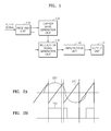
- FIG. 1 illustrates an apparatus for outputting an audio signal according to an exemplary embodiment.
- the apparatus for outputting an audio signal includes a receiving unit 110, a carrier wave generation unit 120, a modulation signal generation unit 130, an amplification unit 140, and an output unit 150.
- the receiving unit 110 receives an audio signal.
- the carrier wave generation unit 120 generates a plurality of carrier waves having different phases using the audio signal received through the receiving unit 110.
- the carrier wave generation unit 120 may generate an initial carrier wave, and then generate phase-shifted carrier waves the respective phases of which are shifted from a phase of the initial carrier wave by predetermined phases, respectively.
- the carrier wave generation unit 120 generates carrier waves such that the initial carrier wave and the phase-shifted carrier waves all have different phases from one another.
- the carrier wave generation unit 120 generates an initial carrier wave, and may then generate a first phase-shifted carrier wave a phase of which is shifted from the phase of the initial carrier wave by 90 degrees, and a second phase-shifted carrier wave a phase of which is shifted from the phase of the initial carrier wave by 180 degrees.
- the carrier wave generation unit 120 may determine a number of carrier waves based on a voltage magnitude of the received audio signal, and generate carrier waves according to the determined number. For example, if the voltage level of the audio signal that is currently inputted through the receiving unit 110 corresponds to volume level 3 of volume levels 1 to 10, the carrier wave generation unit 120 may generate three carrier waves based on the volume level 3. Here, phases of the three carrier waves differ from one another.
- the method of determining the number of the carrier waves is not limited to the example above.
- the carrier wave generation unit 120 may generate the carrier waves the number of which equals the number of output units (not shown) included in the output unit 150.
- the range of volume levels is not limited to one of 1 to 10 as described above, and may be subdivided in increments greater or less than the numerical values of 1 to 10 in another exemplary embodiment.
- the modulation signal generation unit 130 receives the audio signal, and compares the respective carrier waves generated from the carrier wave generation unit 120 with the received audio signal to thereby generate a plurality of modulation signals.
- modulation signal generation unit 130 Detailed operation of the modulation signal generation unit 130 will be described later with reference to FIGS. 2A, 2B and 3 .
- FIGS. 2A and 2B illustrate a method of generating one modulation signal according to an exemplary embodiment.
- FIG. 2A illustrates a carrier wave 210 and an audio signal 220 which are inputted to the modulation signal generation unit 130
- FIG. 2B illustrates a modulation signal 230 that the modulation signal generation unit 130 generates by comparing the carrier wave 210 with the audio signal 220.
- the audio signal 220 is a sinusoidal wave.
- the modulation signal 230 has a high level when a voltage magnitude of the carrier wave 210 is equal to or smaller than that of the audio signal 220, and has a low level when the carrier wave 210 is greater in voltage magnitude than the audio signal 220.
- the modulation signal 230 having a low level means that the voltage magnitude of the modulation signal is smaller than a predetermined threshold value
- the modulation signal 230 having a high level means that the voltage magnitude of the modulation signal is equal to or greater than the predetermined threshold value.
- the modulation signal 230 is not limited to the exemplary embodiment of FIGS. 2A and 2B . Therefore, a modulation signal according to another embodiment may have a low level when the carrier wave 210 is smaller in voltage magnitude than the audio signal 220, and may have a high level when the carrier wave 210 is greater in magnitude than the audio signal 220.
- the modulation signal 230 illustrated in FIG. 2B is a pulse width modulation (PWM) signal.
- the modulation signal generation unit 130 of an exemplary embodiment may generate a PWM signal as illustrated in FIG. 2B , or may generate a modulation signal having different waveforms.
- FIGS. 2A and 2B the method of generating one modulation signal has been described.
- description will be given of a method of generating a plurality of modulation signals with reference to FIG. 3 .
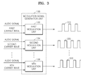
- FIG. 3 illustrates a method of generating a plurality of modulation signals according to an exemplary embodiment.
- the modulation signal generation unit 130 includes N number of modulation units 132, 134, ... , and 136.
- the first modulation unit 132 receives an audio signal and a first carrier wave to generate a first modulation signal 310.
- the second modulation unit 134 receives the audio signal and a second carrier wave to generate a second modulation signal 320.
- the Nth modulation unit 136 receives the audio signal and an Nth carrier wave to generate an Nth modulation signal 330.
- the first to Nth carrier waves 310 to 330 differ in phase from one another.
- high-level periods of some of the first to Nth carrier waves 310 to 330 partly overlap each other.
- the modulation signal generation unit 130 generates modulation signals such that high-level periods of the respective modulation signals partly overlap each other in a time domain.
- the amplification unit 140 amplifies the plurality of modulation signals.
- the amplification unit 140 amplifies amplitudes of voltages or currents of the plurality of modulation signals.
- the modulation signals do not have amplitudes of voltages or currents large enough to drive the output unit 150. For this reason, the amplification unit 140 amplifies voltages or currents of the modulation signals to drive the output unit 150.
- the amplified modulation signals may have voltages or currents having the same magnitude.
- the output unit 150 outputs the amplified modulation signal.
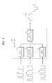
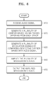
- FIG. 4 illustrates the configuration of the output unit according to an exemplary embodiment.
- the output unit 150 includes N number of voice coils 152a, 152b, ... , and 152c, and an audio output unit 154. That is, the output unit 150 according to an exemplary embodiment may be a speaker including the N number of voice coils 152a, 152b, ... , and 152c, and the audio output unit 154.
- the first voice coil 152a receives a first amplified modulation signal 412 a voltage of which is amplified by the amplification unit 140, and outputs the first amplified modulation signal to the audio output unit 154.
- the second voice coil 152b receives a second amplified modulation signal 414 a voltage of which is amplified by the amplification unit 140, and outputs the second amplified modulation signal to the audio output unit 154.
- the Nth voice coil 152c receives an Nth amplified modulation signal 416 a voltage of which is amplified by the amplification unit 140, and outputs the Nth amplified modulation signal to the audio output unit 154.
- the audio output unit 154 synthesizes the N number of amplified modulation signals 412, 414, ..., and 416 inputted through the N number of voice coils 152a, 152b, ..., and 152c, and outputs a final output signal 420.
- the final output signal 420 illustrated in FIG. 4 is an output signal obtained when the audio signal received by the receiving unit 110 is a sinusoidal wave
- the final output signal 420 also has a waveform similar to the sinusoidal waveform of the received audio signal. Therefore, when the audio signal received by the receiving unit 110 has an arbitrary waveform instead of a sinusoidal waveform, the final output signal 420 also has the arbitrary waveform instead of the sinusoidal waveform.
- the N number of voice coils 152a, 152b, ..., and 152c respectively output the N number of amplified modulation signals 412, 414, ..., and 416 to the audio output unit 154 when the N number of amplified modulation signals 412, 414, ..., and 416 are at logic high.
- the N number of amplified modulation signals 412, 414, ..., and 416 are at logic low, each of the N number of voice coils 152a, 152b, ..., and 152c does not operate, and the N number of amplified modulation signals 412, 414, ..., and 416 have high or low levels at random intervals.
- the conventional method and apparatus must use a complex algorithm such as dynamic element matching (DEM) algorithm in order to overcome the performance difference, which causes computation amount to be increased due to the application of the complex algorithm.
- a complex algorithm such as dynamic element matching (DEM) algorithm
- EDM dynamic element matching
- the performance difference between the voice coils 152a, 152b, ..., and 152c can be prevented without the complex computation that has been necessitated in the conventional method and apparatus.
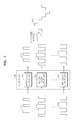
- FIG. 5 illustrates the configuration of an output unit according to another exemplary embodiment.
- the output unit 150 includes N number of audio output units 151, 153, ..., and 155. That is, the output unit 150 according to an exemplary embodiment may be a speaker including the N number of audio output units 151, 153, ..., and 155.
- the first audio output unit 151 receives a first amplified modulation signal 512 a voltage of which is amplified by the amplification unit 140, and outputs the first amplified modulation signal.
- the second audio output unit 153 receives a second amplified modulation signal 514 a voltage of which is amplified by the amplification unit 140, and outputs the second amplified modulation signal.
- the Nth audio output unit 155 receives an Nth amplified modulation signal 516 a voltage of which is amplified by the amplification unit 140, and outputs the Nth amplified modulation signal.
- N number of audio output units 151, 153, ..., and 155 output N number of amplified modulation signals 512, 514, ..., and 516 spatially
- the outputted N number of amplified modulation signals 512, 514, ..., and 516 are synthesized in space. Therefore, a user located in that space recognizes that the final output signal 520, which is generated by synthesizing the N number of amplified modulation signals 512, 514, ..., and 516 through the output unit 150, is outputted.
- the N number of audio output units 151, 153, ..., and 155 respectively output the N number of amplified modulation signals 512, 514, ..., and 516 spatially when the N number of amplified modulation signals 512, 514, ..., and 516 are at logic high.
- the N number of amplified modulation signals 512, 514, ..., and 516 are at logic low, each of the N number of audio output units 151, 153, ..., and 155 does not operate and the N number of amplified modulation signals 412, 414, ..., and 416 have high or low levels at random intervals.
- the conventional method and apparatus must use a complex algorithm such as dynamic element matching (DEM) algorithm in order to overcome the performance difference, which causes computation amount to be increased due to the application of the complex algorithm.
- a complex algorithm such as dynamic element matching (DEM) algorithm
- EDM dynamic element matching
- the performance difference between the audio output units 151, 153, ..., and 155 can be prevented without the complex computation that has been necessitated in the conventional method and apparatus.
- the output unit 150 illustrated in FIGS. 4 and 5 is a speaker employing a half-bridge architecture. However, in the case where the output unit 150 in FIGS. 4 and 5 is a speaker employing a full-bridge architecture, the number of voice coils 152a, 152b, ..., and 152c included in the output unit 150 of FIG. 4 , or the number of audio output units 151, 153, ..., and 155 included in the output unit 150 of FIG. 5 , is reduced.
- the voice coils 152a, 152b, ..., and 152c, or the audio output units 151, 153, ..., and 155 may have a positive input unit and a negative input unit, wherein an amplified modulation signal inputted to the positive input unit may differ in phase by 180 degrees from an amplified modulation signal inputted to the negative input unit.
- a speaker having the half-bridge architecture necessitates four voice coils for outputting four amplified modulation signals
- the speaker having the full-bridge architecture necessitates only two voice coils for outputting four amplified modulation signals.
- the carrier wave generation unit 120 may generate a pair of carrier waves having a phase difference of 180 degrees therebetween.
- FIG. 6 is a flowchart illustrating a method of outputting an audio signal according to an exemplary embodiment.
- an audio signal is received.
- the number of the generated carrier waves may be determined based on a voltage magnitude of the received audio signal.
- a plurality of modulation signals are generated by comparing the respective carrier waves with the audio signal.
- the modulation signals are generated such that high-level periods of the respective modulation signals partly overlap each other in a time domain.
- the plurality of modulation signals are amplified.
- the amplified modulation signals are outputted.
- exemplary embodiments may be written as a program to be performed by a computer.
- exemplary embodiments may be realized at a general-purpose computer which operates the program.
- the computer-readable recording medium includes, but is not limited to, a magnetic storage medium (e.g., ROM, floppy disk, hard disk and the like) and an optical reading medium (e.g., CD-ROM, DVD and the like).
- a magnetic storage medium e.g., ROM, floppy disk, hard disk and the like
- an optical reading medium e.g., CD-ROM, DVD and the like
Landscapes
- Engineering & Computer Science (AREA)
- Power Engineering (AREA)
- Signal Processing (AREA)
- Amplifiers (AREA)
Abstract
Description
- Exemplary embodiments relate to a method and an apparatus for outputting an audio signal.
- With the development of acoustic technologies, various techniques for outputting an audio signal have been proposed. One of the techniques is a method of converting a single audio signal into a plurality of audio signals and then outputting the plurality of audio signals through a plurality of audio output units corresponding thereto. According to this method, however, when only some specific audio output units of the plurality of audio output units continue to output audio signals for certain duration, there are performance differences between the specific audio output units continuing to output the audio signals and the other audio output units which do not operate to output audio signals. That is, the frequent use of specific audio output units leads to a problem in that the performances of the specific audio output units continuously outputting audio signals are further degraded in comparison with the performances of the other audio output units which do not operate to output audio signals.
- To overcome such a problem, a method of randomly changing audio signal output units at a predetermined period using a dynamic element matching (DEM) algorithm has been proposed to prevent only specific audio output units from continuing to output audio signals. However, such a conventional method causes computation amount to be increased due to the application of the complex algorithm.
- Exemplary embodiments provide a method and an apparatus for outputting an audio signal.
- Exemplary embodiments address the above disadvantages and other disadvantages not described above. Also, exemplary embodiments are not required to address the disadvantages described above and an exemplary embodiment may not address any of the disadvantages described above.
- According to an exemplary embodiment, there is provided a method of outputting an audio signal, including receiving an audio signal; generating a plurality of carrier waves having phases differing from each other; generating a plurality of modulation signals by comparing the respective carrier waves with the audio signal; amplifying the plurality of modulation signals; and outputting the amplified modulation signals.
- Each of the modulation signals may have a first logic level or a second logic level, and the generating of the modulation signals may be performed such that first logic level periods of the respective modulation signals partly overlap each other in a time domain.
- In the outputting of the amplified modulation signals, the amplified modulation signals may be outputted through a speaker including a plurality of audio output units that are provided for directly outputting the respective amplified modulation signals.
- The method may further include synthesizing and outputting the amplified modulation signals outputted from a plurality of voice coils when the amplified modulation signals are outputted through the plurality of voice coils.
- The generating of the plurality of carrier waves may include generating an initial carrier wave; and generating phase-shifted carrier waves the phases of which are shifted from a phase of the initial carrier wave by predetermined phases, and the initial carrier wave and the phase-shifted waves all may differ in phase from one another.
- In the generating of the plurality of carrier waves, a pair of carrier waves having a phase difference of 180 degrees therebetween may be generated.
- The generating of the carrier waves may include determining a number of the carrier waves based on a voltage magnitude of the received audio signal; and generating the carrier waves according to the determined number.
- The modulation signals may be pulse width modulation (PWM) signals.
- In the generating of the modulation signals, the modulation signals may be generated such that the modulation signal has a first logic level when a voltage magnitude of the carrier wave is equal to or smaller than that of the audio signal and the modulation signal has a second logic level when a voltage magnitude of the carrier wave is greater than that of the audio signal.
- According to another exemplary embodiment, there is provided an apparatus for outputting an audio signal, including a receiving unit configured to receive an audio signal; a carrier wave generation unit configured to generate a plurality of carrier waves having phases differing from each other; a modulation signal generation unit configured to generate a plurality of modulation signals by comparing the respective carrier waves with the audio signal; an amplification unit configured to amplify the plurality of modulation signals; and an output unit configured to output the amplified modulation signals.
- The output unit may include a speaker including a plurality of audio output units provided for directly outputting the respective amplified modulation signals.
- The output unit may include a speaker including a plurality of voice coils and an audio output unit, the plurality of voice coils outputting the amplified modulation signals respectively, and the audio output unit synthesizing and outputting the amplified modulation signals outputted from the plurality of voice coils.
- According to another exemplary embodiment, there is provided a computer-readable recording medium storing a program for performing the method of outputting an audio signal, including receiving an audio signal; generating a plurality of carrier waves having phases differing from each other; generating a plurality of modulation signals by comparing the respective carrier waves with the audio signal; amplifying the plurality of modulation signals; and outputting the amplified modulation signals.
- According to the present invention there is provided an apparatus and method as set forth in the appended claims. Other features of the invention will be apparent from the dependent claims, and the description which follows.
- The above and other features will become more apparent by describing in detail exemplary embodiments thereof with reference to the attached drawings, in which:
-
FIG. 1 illustrates an apparatus for outputting an audio signal according to an exemplary embodiment; -
FIGS. 2A and 2B illustrate a method of generating one modulation signal according to an exemplary embodiment; -
FIG. 3 illustrates a method of generating a plurality of modulation signals according to an exemplary embodiment; -
FIG. 4 illustrates the configuration of the output unit according to an exemplary embodiment; -
FIG. 5 illustrates the configuration of an output unit according to another exemplary embodiment; and -
FIG. 6 is a flowchart illustrating a method of outputting an audio signal according to an exemplary embodiment. - Exemplary embodiments will now be described in detail with reference to the accompanying drawings.
-
FIG. 1 illustrates an apparatus for outputting an audio signal according to an exemplary embodiment. - Referring to
FIG. 1 , the apparatus for outputting an audio signal according to an exemplary embodiment includes areceiving unit 110, a carrierwave generation unit 120, a modulationsignal generation unit 130, anamplification unit 140, and anoutput unit 150. - The
receiving unit 110 receives an audio signal. - The carrier
wave generation unit 120 generates a plurality of carrier waves having different phases using the audio signal received through thereceiving unit 110. - For example, the carrier
wave generation unit 120 may generate an initial carrier wave, and then generate phase-shifted carrier waves the respective phases of which are shifted from a phase of the initial carrier wave by predetermined phases, respectively. Here, the carrierwave generation unit 120 generates carrier waves such that the initial carrier wave and the phase-shifted carrier waves all have different phases from one another. As an exemplary embodiment, the carrierwave generation unit 120 generates an initial carrier wave, and may then generate a first phase-shifted carrier wave a phase of which is shifted from the phase of the initial carrier wave by 90 degrees, and a second phase-shifted carrier wave a phase of which is shifted from the phase of the initial carrier wave by 180 degrees. - The carrier
wave generation unit 120 may determine a number of carrier waves based on a voltage magnitude of the received audio signal, and generate carrier waves according to the determined number. For example, if the voltage level of the audio signal that is currently inputted through the receivingunit 110 corresponds to volume level 3 of volume levels 1 to 10, the carrierwave generation unit 120 may generate three carrier waves based on the volume level 3. Here, phases of the three carrier waves differ from one another. - The method of determining the number of the carrier waves is not limited to the example above. For instance, the carrier
wave generation unit 120 may generate the carrier waves the number of which equals the number of output units (not shown) included in theoutput unit 150. The range of volume levels is not limited to one of 1 to 10 as described above, and may be subdivided in increments greater or less than the numerical values of 1 to 10 in another exemplary embodiment. - The modulation
signal generation unit 130 receives the audio signal, and compares the respective carrier waves generated from the carrierwave generation unit 120 with the received audio signal to thereby generate a plurality of modulation signals. - Detailed operation of the modulation
signal generation unit 130 will be described later with reference toFIGS. 2A, 2B and3 . -
FIGS. 2A and 2B illustrate a method of generating one modulation signal according to an exemplary embodiment. - In particular,
FIG. 2A illustrates acarrier wave 210 and anaudio signal 220 which are inputted to the modulationsignal generation unit 130, andFIG. 2B illustrates amodulation signal 230 that the modulationsignal generation unit 130 generates by comparing thecarrier wave 210 with theaudio signal 220. For convenience in describing the exemplary embodiment ofFIGS. 2A and 2B , it is assumed that theaudio signal 220 is a sinusoidal wave. - Referring to
FIG. 2B , themodulation signal 230 according to an exemplary embodiment has a high level when a voltage magnitude of thecarrier wave 210 is equal to or smaller than that of theaudio signal 220, and has a low level when thecarrier wave 210 is greater in voltage magnitude than theaudio signal 220. Themodulation signal 230 having a low level means that the voltage magnitude of the modulation signal is smaller than a predetermined threshold value, whereas themodulation signal 230 having a high level means that the voltage magnitude of the modulation signal is equal to or greater than the predetermined threshold value. However, themodulation signal 230 is not limited to the exemplary embodiment ofFIGS. 2A and 2B . Therefore, a modulation signal according to another embodiment may have a low level when thecarrier wave 210 is smaller in voltage magnitude than theaudio signal 220, and may have a high level when thecarrier wave 210 is greater in magnitude than theaudio signal 220. - In particular, the
modulation signal 230 illustrated inFIG. 2B is a pulse width modulation (PWM) signal. The modulationsignal generation unit 130 of an exemplary embodiment may generate a PWM signal as illustrated inFIG. 2B , or may generate a modulation signal having different waveforms. - In
FIGS. 2A and 2B , the method of generating one modulation signal has been described. Hereinafter, description will be given of a method of generating a plurality of modulation signals with reference toFIG. 3 . -
FIG. 3 illustrates a method of generating a plurality of modulation signals according to an exemplary embodiment. - Referring to
FIG. 3 , the modulationsignal generation unit 130 according to an exemplary embodiment includes N number ofmodulation units - The
first modulation unit 132 receives an audio signal and a first carrier wave to generate afirst modulation signal 310. - The
second modulation unit 134 receives the audio signal and a second carrier wave to generate asecond modulation signal 320. - The
Nth modulation unit 136 receives the audio signal and an Nth carrier wave to generate anNth modulation signal 330. - Here, the first to
Nth carrier waves 310 to 330 differ in phase from one another. - Also, referring to
FIG. 3 , high-level periods of some of the first toNth carrier waves 310 to 330 partly overlap each other. - As such, the modulation
signal generation unit 130 according to an exemplary embodiment generates modulation signals such that high-level periods of the respective modulation signals partly overlap each other in a time domain. - The
amplification unit 140 amplifies the plurality of modulation signals. - More specifically, the
amplification unit 140 amplifies amplitudes of voltages or currents of the plurality of modulation signals. - In general, the modulation signals do not have amplitudes of voltages or currents large enough to drive the
output unit 150. For this reason, theamplification unit 140 amplifies voltages or currents of the modulation signals to drive theoutput unit 150. In an exemplary embodiment, the amplified modulation signals may have voltages or currents having the same magnitude. - The
output unit 150 outputs the amplified modulation signal. - Detailed operation of the
output unit 150 according to an exemplary embodiment will be described with reference toFIGS. 4 and5 . -
FIG. 4 illustrates the configuration of the output unit according to an exemplary embodiment. - Referring to
FIG. 4 , theoutput unit 150 according to an exemplary embodiment includes N number ofvoice coils audio output unit 154. That is, theoutput unit 150 according to an exemplary embodiment may be a speaker including the N number ofvoice coils audio output unit 154. - The
first voice coil 152a receives a first amplified modulation signal 412 a voltage of which is amplified by theamplification unit 140, and outputs the first amplified modulation signal to theaudio output unit 154. - The
second voice coil 152b receives a second amplified modulation signal 414 a voltage of which is amplified by theamplification unit 140, and outputs the second amplified modulation signal to theaudio output unit 154. - The
Nth voice coil 152c receives an Nth amplified modulation signal 416 a voltage of which is amplified by theamplification unit 140, and outputs the Nth amplified modulation signal to theaudio output unit 154. - The
audio output unit 154 synthesizes the N number of amplified modulation signals 412, 414, ..., and 416 inputted through the N number ofvoice coils final output signal 420. - Since the
final output signal 420 illustrated inFIG. 4 is an output signal obtained when the audio signal received by the receivingunit 110 is a sinusoidal wave, thefinal output signal 420 also has a waveform similar to the sinusoidal waveform of the received audio signal. Therefore, when the audio signal received by the receivingunit 110 has an arbitrary waveform instead of a sinusoidal waveform, thefinal output signal 420 also has the arbitrary waveform instead of the sinusoidal waveform. - In an exemplary embodiment, the N number of
voice coils audio output unit 154 when the N number of amplified modulation signals 412, 414, ..., and 416 are at logic high. On the contrary, when the N number of amplified modulation signals 412, 414, ..., and 416 are at logic low, each of the N number ofvoice coils voice coils voice coils - Also, the conventional method and apparatus must use a complex algorithm such as dynamic element matching (DEM) algorithm in order to overcome the performance difference, which causes computation amount to be increased due to the application of the complex algorithm. However, according to an exemplary embodiment, the performance difference between the
voice coils -
FIG. 5 illustrates the configuration of an output unit according to another exemplary embodiment. - Referring to
FIG. 5 , theoutput unit 150 according to an exemplary embodiment includes N number ofaudio output units output unit 150 according to an exemplary embodiment may be a speaker including the N number ofaudio output units - The first
audio output unit 151 receives a first amplified modulation signal 512 a voltage of which is amplified by theamplification unit 140, and outputs the first amplified modulation signal. - The second
audio output unit 153 receives a second amplified modulation signal 514 a voltage of which is amplified by theamplification unit 140, and outputs the second amplified modulation signal. - The Nth
audio output unit 155 receives an Nth amplified modulation signal 516 a voltage of which is amplified by theamplification unit 140, and outputs the Nth amplified modulation signal. - As such, when the N number of
audio output units final output signal 520, which is generated by synthesizing the N number of amplified modulation signals 512, 514, ..., and 516 through theoutput unit 150, is outputted. - In an exemplary embodiment, the N number of
audio output units audio output units audio output units audio output units - Also, the conventional method and apparatus must use a complex algorithm such as dynamic element matching (DEM) algorithm in order to overcome the performance difference, which causes computation amount to be increased due to the application of the complex algorithm. However, according to an exemplary embodiment, the performance difference between the
audio output units - The
output unit 150 illustrated inFIGS. 4 and5 is a speaker employing a half-bridge architecture. However, in the case where theoutput unit 150 inFIGS. 4 and5 is a speaker employing a full-bridge architecture, the number ofvoice coils output unit 150 ofFIG. 4 , or the number ofaudio output units output unit 150 ofFIG. 5 , is reduced. - In the full-bridge architecture, the
voice coils audio output units - For example, a speaker having the half-bridge architecture necessitates four voice coils for outputting four amplified modulation signals, whereas the speaker having the full-bridge architecture necessitates only two voice coils for outputting four amplified modulation signals.
- The carrier
wave generation unit 120 according to an exemplary embodiment may generate a pair of carrier waves having a phase difference of 180 degrees therebetween. - The structure and operation of the speaker having the half-bridge architecture and the structure and operation of the speaker having the full-bridge architecture are understood by those of ordinary skill in the art, and accordingly detailed description for them will be omitted herein.
-
FIG. 6 is a flowchart illustrating a method of outputting an audio signal according to an exemplary embodiment. - In
operation 610, an audio signal is received. - In
operation 620, a plurality of carrier waves, the phases of which differ from each other, are generated. - The number of the generated carrier waves may be determined based on a voltage magnitude of the received audio signal.
- In
operation 630, a plurality of modulation signals are generated by comparing the respective carrier waves with the audio signal. - In an exemplary embodiment, the modulation signals are generated such that high-level periods of the respective modulation signals partly overlap each other in a time domain.
- In
operation 640, the plurality of modulation signals are amplified. - In
operation 650, the amplified modulation signals are outputted. - The above-described exemplary embodiments may be written as a program to be performed by a computer. By using a computer-readable recording medium, exemplary embodiments may be realized at a general-purpose computer which operates the program.
- The computer-readable recording medium includes, but is not limited to, a magnetic storage medium (e.g., ROM, floppy disk, hard disk and the like) and an optical reading medium (e.g., CD-ROM, DVD and the like).
- While exemplary embodiments have been particularly shown and described, it will be understood by those of ordinary skill in the art that various changes in form and details may be made therein without departing from the scope of the present invention as defined by the following claims.
Attention is directed to all papers and documents which are filed concurrently with or previous to this specification in connection with this application and which are open to public inspection with this specification, and the contents of all such papers and documents are incorporated herein by reference.
All of th e features disclosed i n this specification (including any accompanying claims, abstract and drawings), and/or all of the steps of any method or process so disclosed, may be combined in any combination, except combinations where at least some of such features and/or steps are mutually exclusive.
Each feature disclosed in this specification (including any accompanying claims, abstract and drawings) may be replaced by alternative features serving the same, equivalent or similar purpose, unless expressly stated otherwise. Thus, unless expressly stated otherwise, each feature disclosed is one example only of a generic series of equivalent or similar features.
The invention is not restricted to the details of the foregoing embodiment(s). The invention extends to any novel one, or any novel combination, of the features disclosed in this specification (including any accompanying claims, abstract and drawings), or to any novel one, or any novel combination, of the steps of any method or process so disclosed.
Claims (15)
- A method of outputting amplified modulation signals from an audio signal, the method comprising:receiving the audio signal;generating carrier waves, each one of the carrier waves having a respective phase that differs from all other ones of the carrier waves;generating modulation signals by comparing each one of the carrier waves with the received audio signal;amplifying the modulation signals; andoutputting the amplified modulation signals.
- The method of claim 1, wherein first one of the modulation signals comprises a first logic level and a second logic level, and
wherein the generating the modulation signals is performed such that first logic level periods of the first one of the modulation signals partly overlap with first logic level periods of a second one of the modulation signals in a time domain. - The method of claim 1, wherein the outputting the amplified modulation signals comprises outputting the amplified modulation signals through a speaker comprising audio output units that are provided for directly outputting respective ones of the amplified modulation signals.
- The method of claim 1, further comprising:outputting the amplified modulation signals from voice coils; andsynthesizing the amplified modulation signals that are outputted from the voice coils.
- The method of claim 1, wherein the generating the carrier waves comprises:generating an initial carrier wave; andgenerating phase-shifted carrier waves,wherein a respective phase of each one of the phase-shifted carrier waves is shifted from a phase of the initial carrier wave by a predetermined respective phase shift, andwherein each one of the initial carrier wave and the phase-shifted waves has a phase that differs from all other ones of the initial carrier wave and the phase-shifted waves.
- The method of claim 1, wherein the generating the carrier waves comprises:determining a number of the carrier waves based on a voltage magnitude of the received audio signal; andgenerating the determined number of carrier waves.
- The method of claim 1, wherein in the generating the modulation signals, the modulation signals are generated such that each one of the modulation signals comprises a first logic level when a voltage magnitude of a respective one of the carrier waves is equal to or smaller than a voltage magnitude of the audio signal, and such that each one of the modulation signals comprises a second logic level when a voltage magnitude of a respective one of the carrier waves is greater than a voltage magnitude of the audio signal.
- An apparatus for outputting amplified modulation signals from an audio signal, the apparatus comprising:a receiving unit configured to receive the audio signal;a carrier wave generation unit configured to generate carrier waves, each one of the carrier waves having a respective phase that differs from all other ones of the carrier waves;a modulation signal generation unit configured to generate modulation signals by comparing each one of the carrier waves with the audio signal;an amplification unit configured to amplify the modulation signals; andan output unit configured to output the amplified modulation signals.
- The apparatus of claim 8, wherein each one of the modulation signals comprises a first logic level and a second logic level, and
wherein the modulation signal generation unit generates the modulation signals such that first logic level periods of a first one of the modulation signals partly overlap with first logic level periods of a second one of the modulation signals in a time domain. - The apparatus of claim 8, wherein the output unit comprises a speaker including audio output units configured to directly output the respective ones of the amplified modulation signals.
- The apparatus of claim 8, wherein the output unit comprises a speaker including voice coils and an audio output unit,
wherein the voice coils are configured to output respective ones of the amplified modulation signals, and
wherein the audio output unit is configured to synthesize the amplified modulation signals outputted from the voice coils. - The apparatus of claim 8, wherein the carrier wave generation unit is configured to generate an initial carrier wave and to generate phase-shifted carrier waves,
wherein a respective phase of each one of the phase-shifted carrier waves is shifted from a phase of the initial carrier wave by a predetermined respective phase shift, and
wherein each one of the initial carrier wave and the phase-shifted waves has a phase that differs from all other ones of the initial carrier wave and the phase-shifted waves. - The apparatus of claim 8, wherein the modulation signal generation unit is configured to generate the modulation signals such that each one of the modulation signals has a first logic level when a voltage magnitude of a respective one of the carrier waves is equal to or smaller than a voltage magnitude of the audio signal, and such that each one of the modulation signals has a second logic level when a voltage magnitude of the respective one of the carrier waves is greater than a voltage magnitude of the audio signal.
- The apparatus of claim 8, wherein the carrier wave generation unit is configured to determine a number of the carrier waves based on a voltage magnitude of the received audio signal, and
wherein the carrier wave generation unit is configured to generate the determined number of carrier waves. - A non-transitory computer-readable recording medium storing a program for causing a computer to execute operations comprising:receiving an audio signal at a receiving unit;generating, by a carrier wave generation unit, carrier waves, each one of the carrier waves having a respective phase that differs from all other ones of the carrier waves;generating, by a modulation signal generation unit, modulation signals by comparing each one of the carrier waves with the audio signal;amplifying, by an amplification unit, the modulation signals; andoutputting, by an output unit, the amplified modulation signals.
Applications Claiming Priority (1)
| Application Number | Priority Date | Filing Date | Title |
|---|---|---|---|
| KR1020100001898A KR101664431B1 (en) | 2010-01-08 | 2010-01-08 | Audio signal output method and apparatus |
Publications (2)
| Publication Number | Publication Date |
|---|---|
| EP2355352A1 true EP2355352A1 (en) | 2011-08-10 |
| EP2355352B1 EP2355352B1 (en) | 2013-03-20 |
Family
ID=43901274
Family Applications (1)
| Application Number | Title | Priority Date | Filing Date |
|---|---|---|---|
| EP10189946A Not-in-force EP2355352B1 (en) | 2010-01-08 | 2010-11-04 | Method and apparatus for outputting audio signal |
Country Status (3)
| Country | Link |
|---|---|
| US (1) | US8625821B2 (en) |
| EP (1) | EP2355352B1 (en) |
| KR (1) | KR101664431B1 (en) |
Families Citing this family (1)
| Publication number | Priority date | Publication date | Assignee | Title |
|---|---|---|---|---|
| KR101683174B1 (en) * | 2010-01-08 | 2016-12-06 | 삼성전자주식회사 | Method and Apparatus for amplifying audio signal |
Citations (3)
| Publication number | Priority date | Publication date | Assignee | Title |
|---|---|---|---|---|
| US4164714A (en) * | 1977-09-26 | 1979-08-14 | Harris Corporation | Polyphase PDM amplifier |
| US5216376A (en) * | 1992-06-10 | 1993-06-01 | Harris Corporation | Pulse duration amplifier system having distortion reduction |
| JP2001127562A (en) * | 1999-10-25 | 2001-05-11 | Susumu Kimura | Pwm power amplifier |
Family Cites Families (3)
| Publication number | Priority date | Publication date | Assignee | Title |
|---|---|---|---|---|
| US4580111A (en) * | 1981-12-24 | 1986-04-01 | Harris Corporation | Amplitude modulation using digitally selected carrier amplifiers |
| TWI340286B (en) * | 2006-10-12 | 2011-04-11 | Chunghwa Picture Tubes Ltd | Pixel structure |
| KR101683174B1 (en) * | 2010-01-08 | 2016-12-06 | 삼성전자주식회사 | Method and Apparatus for amplifying audio signal |
-
2010
- 2010-01-08 KR KR1020100001898A patent/KR101664431B1/en not_active Expired - Fee Related
- 2010-07-13 US US12/835,176 patent/US8625821B2/en not_active Expired - Fee Related
- 2010-11-04 EP EP10189946A patent/EP2355352B1/en not_active Not-in-force
Patent Citations (4)
| Publication number | Priority date | Publication date | Assignee | Title |
|---|---|---|---|---|
| US4164714A (en) * | 1977-09-26 | 1979-08-14 | Harris Corporation | Polyphase PDM amplifier |
| US4164714B1 (en) * | 1977-09-26 | 1984-12-25 | ||
| US5216376A (en) * | 1992-06-10 | 1993-06-01 | Harris Corporation | Pulse duration amplifier system having distortion reduction |
| JP2001127562A (en) * | 1999-10-25 | 2001-05-11 | Susumu Kimura | Pwm power amplifier |
Also Published As
| Publication number | Publication date |
|---|---|
| US8625821B2 (en) | 2014-01-07 |
| KR20110081641A (en) | 2011-07-14 |
| US20110170719A1 (en) | 2011-07-14 |
| KR101664431B1 (en) | 2016-10-10 |
| EP2355352B1 (en) | 2013-03-20 |
Similar Documents
| Publication | Publication Date | Title |
|---|---|---|
| US8866544B2 (en) | Class D pulse width modulator with dual feedback | |
| US20080130915A1 (en) | Audio reproducing apparatus | |
| US11342892B2 (en) | Amplifier and signal processing circuit | |
| CN100553122C (en) | Multi-channel digital amplifier, its signal processing method and its audio reproduction system | |
| JP6533959B2 (en) | Audio signal processing apparatus and audio signal processing method | |
| EP2355352A1 (en) | Method and apparatus for outputting audio signal | |
| JP4882353B2 (en) | Pulse width modulation amplifier | |
| JP2006093749A (en) | Audio power amplifier ic and audio system equipped therewith | |
| JP6301592B2 (en) | Failure detection device | |
| US9130513B2 (en) | Method and apparatus for amplifying audio signal | |
| US20220407609A1 (en) | Sound field generator, sound field generation method, and program | |
| JP6304942B2 (en) | Power converter, control method for power converter, and control program | |
| US11990114B2 (en) | Combined wave data generation method, combined wave data generation program, storage medium, combined wave data generation device, and waveform data generation method | |
| JP2010193206A (en) | Acoustic field correction method and an acoustic field correction device | |
| US20240422478A1 (en) | Computer-implemented bass enhancement method and bass enhancement apparatus | |
| JP2014057208A (en) | Sweep signal generation apparatus, sweep signal generation method and program | |
| JP4222492B2 (en) | Audio power amplifier IC and audio system including the same | |
| US9431979B2 (en) | Method and apparatus for emulating sound | |
| US20150380633A1 (en) | Apparatus for driving piezoelectric element and method for driving piezoelectric element | |
| US20220191074A1 (en) | Signal processing device, signal processing method, and program | |
| JP2016213725A (en) | Signal reproduction device | |
| JP2023184780A (en) | Signal processing device and multiplex sound emitting device | |
| JP2017062340A (en) | Output control device, output control method, and program | |
| JP2011159377A (en) | Data output circuit of semiconductor memory and control method of the same | |
| JP2011107265A (en) | Embedding device for information into sound signal |
Legal Events
| Date | Code | Title | Description |
|---|---|---|---|
| PUAI | Public reference made under article 153(3) epc to a published international application that has entered the european phase |
Free format text: ORIGINAL CODE: 0009012 |
|
| AK | Designated contracting states |
Kind code of ref document: A1 Designated state(s): AL AT BE BG CH CY CZ DE DK EE ES FI FR GB GR HR HU IE IS IT LI LT LU LV MC MK MT NL NO PL PT RO RS SE SI SK SM TR |
|
| AX | Request for extension of the european patent |
Extension state: BA ME |
|
| 17P | Request for examination filed |
Effective date: 20120209 |
|
| 17Q | First examination report despatched |
Effective date: 20120316 |
|
| RAP1 | Party data changed (applicant data changed or rights of an application transferred) |
Owner name: SAMSUNG ELECTRONICS CO., LTD. |
|
| GRAP | Despatch of communication of intention to grant a patent |
Free format text: ORIGINAL CODE: EPIDOSNIGR1 |
|
| GRAS | Grant fee paid |
Free format text: ORIGINAL CODE: EPIDOSNIGR3 |
|
| GRAA | (expected) grant |
Free format text: ORIGINAL CODE: 0009210 |
|
| AK | Designated contracting states |
Kind code of ref document: B1 Designated state(s): AL AT BE BG CH CY CZ DE DK EE ES FI FR GB GR HR HU IE IS IT LI LT LU LV MC MK MT NL NO PL PT RO RS SE SI SK SM TR |
|
| REG | Reference to a national code |
Ref country code: GB Ref legal event code: FG4D |
|
| REG | Reference to a national code |
Ref country code: CH Ref legal event code: EP |
|
| REG | Reference to a national code |
Ref country code: IE Ref legal event code: FG4D |
|
| REG | Reference to a national code |
Ref country code: AT Ref legal event code: REF Ref document number: 602599 Country of ref document: AT Kind code of ref document: T Effective date: 20130415 |
|
| REG | Reference to a national code |
Ref country code: DE Ref legal event code: R096 Ref document number: 602010005566 Country of ref document: DE Effective date: 20130516 |
|
| PG25 | Lapsed in a contracting state [announced via postgrant information from national office to epo] |
Ref country code: BG Free format text: LAPSE BECAUSE OF FAILURE TO SUBMIT A TRANSLATION OF THE DESCRIPTION OR TO PAY THE FEE WITHIN THE PRESCRIBED TIME-LIMIT Effective date: 20130620 Ref country code: ES Free format text: LAPSE BECAUSE OF FAILURE TO SUBMIT A TRANSLATION OF THE DESCRIPTION OR TO PAY THE FEE WITHIN THE PRESCRIBED TIME-LIMIT Effective date: 20130701 Ref country code: NO Free format text: LAPSE BECAUSE OF FAILURE TO SUBMIT A TRANSLATION OF THE DESCRIPTION OR TO PAY THE FEE WITHIN THE PRESCRIBED TIME-LIMIT Effective date: 20130620 Ref country code: LT Free format text: LAPSE BECAUSE OF FAILURE TO SUBMIT A TRANSLATION OF THE DESCRIPTION OR TO PAY THE FEE WITHIN THE PRESCRIBED TIME-LIMIT Effective date: 20130320 Ref country code: SE Free format text: LAPSE BECAUSE OF FAILURE TO SUBMIT A TRANSLATION OF THE DESCRIPTION OR TO PAY THE FEE WITHIN THE PRESCRIBED TIME-LIMIT Effective date: 20130320 |
|
| REG | Reference to a national code |
Ref country code: AT Ref legal event code: MK05 Ref document number: 602599 Country of ref document: AT Kind code of ref document: T Effective date: 20130320 |
|
| REG | Reference to a national code |
Ref country code: LT Ref legal event code: MG4D |
|
| PG25 | Lapsed in a contracting state [announced via postgrant information from national office to epo] |
Ref country code: GR Free format text: LAPSE BECAUSE OF FAILURE TO SUBMIT A TRANSLATION OF THE DESCRIPTION OR TO PAY THE FEE WITHIN THE PRESCRIBED TIME-LIMIT Effective date: 20130621 Ref country code: FI Free format text: LAPSE BECAUSE OF FAILURE TO SUBMIT A TRANSLATION OF THE DESCRIPTION OR TO PAY THE FEE WITHIN THE PRESCRIBED TIME-LIMIT Effective date: 20130320 Ref country code: LV Free format text: LAPSE BECAUSE OF FAILURE TO SUBMIT A TRANSLATION OF THE DESCRIPTION OR TO PAY THE FEE WITHIN THE PRESCRIBED TIME-LIMIT Effective date: 20130320 Ref country code: SI Free format text: LAPSE BECAUSE OF FAILURE TO SUBMIT A TRANSLATION OF THE DESCRIPTION OR TO PAY THE FEE WITHIN THE PRESCRIBED TIME-LIMIT Effective date: 20130320 |
|
| REG | Reference to a national code |
Ref country code: NL Ref legal event code: VDEP Effective date: 20130320 |
|
| PG25 | Lapsed in a contracting state [announced via postgrant information from national office to epo] |
Ref country code: RS Free format text: LAPSE BECAUSE OF FAILURE TO SUBMIT A TRANSLATION OF THE DESCRIPTION OR TO PAY THE FEE WITHIN THE PRESCRIBED TIME-LIMIT Effective date: 20130320 Ref country code: BE Free format text: LAPSE BECAUSE OF FAILURE TO SUBMIT A TRANSLATION OF THE DESCRIPTION OR TO PAY THE FEE WITHIN THE PRESCRIBED TIME-LIMIT Effective date: 20130320 Ref country code: HR Free format text: LAPSE BECAUSE OF FAILURE TO SUBMIT A TRANSLATION OF THE DESCRIPTION OR TO PAY THE FEE WITHIN THE PRESCRIBED TIME-LIMIT Effective date: 20130320 |
|
| PG25 | Lapsed in a contracting state [announced via postgrant information from national office to epo] |
Ref country code: IS Free format text: LAPSE BECAUSE OF FAILURE TO SUBMIT A TRANSLATION OF THE DESCRIPTION OR TO PAY THE FEE WITHIN THE PRESCRIBED TIME-LIMIT Effective date: 20130720 Ref country code: CZ Free format text: LAPSE BECAUSE OF FAILURE TO SUBMIT A TRANSLATION OF THE DESCRIPTION OR TO PAY THE FEE WITHIN THE PRESCRIBED TIME-LIMIT Effective date: 20130320 Ref country code: NL Free format text: LAPSE BECAUSE OF FAILURE TO SUBMIT A TRANSLATION OF THE DESCRIPTION OR TO PAY THE FEE WITHIN THE PRESCRIBED TIME-LIMIT Effective date: 20130320 Ref country code: SK Free format text: LAPSE BECAUSE OF FAILURE TO SUBMIT A TRANSLATION OF THE DESCRIPTION OR TO PAY THE FEE WITHIN THE PRESCRIBED TIME-LIMIT Effective date: 20130320 Ref country code: RO Free format text: LAPSE BECAUSE OF FAILURE TO SUBMIT A TRANSLATION OF THE DESCRIPTION OR TO PAY THE FEE WITHIN THE PRESCRIBED TIME-LIMIT Effective date: 20130320 Ref country code: PT Free format text: LAPSE BECAUSE OF FAILURE TO SUBMIT A TRANSLATION OF THE DESCRIPTION OR TO PAY THE FEE WITHIN THE PRESCRIBED TIME-LIMIT Effective date: 20130722 Ref country code: EE Free format text: LAPSE BECAUSE OF FAILURE TO SUBMIT A TRANSLATION OF THE DESCRIPTION OR TO PAY THE FEE WITHIN THE PRESCRIBED TIME-LIMIT Effective date: 20130320 Ref country code: AT Free format text: LAPSE BECAUSE OF FAILURE TO SUBMIT A TRANSLATION OF THE DESCRIPTION OR TO PAY THE FEE WITHIN THE PRESCRIBED TIME-LIMIT Effective date: 20130320 |
|
| PG25 | Lapsed in a contracting state [announced via postgrant information from national office to epo] |
Ref country code: PL Free format text: LAPSE BECAUSE OF FAILURE TO SUBMIT A TRANSLATION OF THE DESCRIPTION OR TO PAY THE FEE WITHIN THE PRESCRIBED TIME-LIMIT Effective date: 20130320 Ref country code: CY Free format text: LAPSE BECAUSE OF FAILURE TO SUBMIT A TRANSLATION OF THE DESCRIPTION OR TO PAY THE FEE WITHIN THE PRESCRIBED TIME-LIMIT Effective date: 20130320 |
|
| PLBE | No opposition filed within time limit |
Free format text: ORIGINAL CODE: 0009261 |
|
| STAA | Information on the status of an ep patent application or granted ep patent |
Free format text: STATUS: NO OPPOSITION FILED WITHIN TIME LIMIT |
|
| PG25 | Lapsed in a contracting state [announced via postgrant information from national office to epo] |
Ref country code: DK Free format text: LAPSE BECAUSE OF FAILURE TO SUBMIT A TRANSLATION OF THE DESCRIPTION OR TO PAY THE FEE WITHIN THE PRESCRIBED TIME-LIMIT Effective date: 20130320 |
|
| 26N | No opposition filed |
Effective date: 20140102 |
|
| PG25 | Lapsed in a contracting state [announced via postgrant information from national office to epo] |
Ref country code: IT Free format text: LAPSE BECAUSE OF FAILURE TO SUBMIT A TRANSLATION OF THE DESCRIPTION OR TO PAY THE FEE WITHIN THE PRESCRIBED TIME-LIMIT Effective date: 20130320 |
|
| REG | Reference to a national code |
Ref country code: DE Ref legal event code: R097 Ref document number: 602010005566 Country of ref document: DE Effective date: 20140102 |
|
| PG25 | Lapsed in a contracting state [announced via postgrant information from national office to epo] |
Ref country code: MC Free format text: LAPSE BECAUSE OF FAILURE TO SUBMIT A TRANSLATION OF THE DESCRIPTION OR TO PAY THE FEE WITHIN THE PRESCRIBED TIME-LIMIT Effective date: 20130320 |
|
| REG | Reference to a national code |
Ref country code: FR Ref legal event code: ST Effective date: 20140731 |
|
| REG | Reference to a national code |
Ref country code: IE Ref legal event code: MM4A |
|
| PG25 | Lapsed in a contracting state [announced via postgrant information from national office to epo] |
Ref country code: IE Free format text: LAPSE BECAUSE OF NON-PAYMENT OF DUE FEES Effective date: 20131104 |
|
| PG25 | Lapsed in a contracting state [announced via postgrant information from national office to epo] |
Ref country code: FR Free format text: LAPSE BECAUSE OF NON-PAYMENT OF DUE FEES Effective date: 20131202 |
|
| PG25 | Lapsed in a contracting state [announced via postgrant information from national office to epo] |
Ref country code: SM Free format text: LAPSE BECAUSE OF FAILURE TO SUBMIT A TRANSLATION OF THE DESCRIPTION OR TO PAY THE FEE WITHIN THE PRESCRIBED TIME-LIMIT Effective date: 20130320 |
|
| PG25 | Lapsed in a contracting state [announced via postgrant information from national office to epo] |
Ref country code: TR Free format text: LAPSE BECAUSE OF FAILURE TO SUBMIT A TRANSLATION OF THE DESCRIPTION OR TO PAY THE FEE WITHIN THE PRESCRIBED TIME-LIMIT Effective date: 20130320 |
|
| REG | Reference to a national code |
Ref country code: CH Ref legal event code: PL |
|
| PG25 | Lapsed in a contracting state [announced via postgrant information from national office to epo] |
Ref country code: CH Free format text: LAPSE BECAUSE OF NON-PAYMENT OF DUE FEES Effective date: 20141130 Ref country code: HU Free format text: LAPSE BECAUSE OF FAILURE TO SUBMIT A TRANSLATION OF THE DESCRIPTION OR TO PAY THE FEE WITHIN THE PRESCRIBED TIME-LIMIT; INVALID AB INITIO Effective date: 20101104 Ref country code: LU Free format text: LAPSE BECAUSE OF NON-PAYMENT OF DUE FEES Effective date: 20131104 Ref country code: LI Free format text: LAPSE BECAUSE OF NON-PAYMENT OF DUE FEES Effective date: 20141130 Ref country code: MK Free format text: LAPSE BECAUSE OF FAILURE TO SUBMIT A TRANSLATION OF THE DESCRIPTION OR TO PAY THE FEE WITHIN THE PRESCRIBED TIME-LIMIT Effective date: 20130320 |
|
| PG25 | Lapsed in a contracting state [announced via postgrant information from national office to epo] |
Ref country code: MT Free format text: LAPSE BECAUSE OF FAILURE TO SUBMIT A TRANSLATION OF THE DESCRIPTION OR TO PAY THE FEE WITHIN THE PRESCRIBED TIME-LIMIT Effective date: 20130320 |
|
| PGFP | Annual fee paid to national office [announced via postgrant information from national office to epo] |
Ref country code: DE Payment date: 20171018 Year of fee payment: 8 |
|
| PGFP | Annual fee paid to national office [announced via postgrant information from national office to epo] |
Ref country code: GB Payment date: 20171019 Year of fee payment: 8 |
|
| PG25 | Lapsed in a contracting state [announced via postgrant information from national office to epo] |
Ref country code: AL Free format text: LAPSE BECAUSE OF FAILURE TO SUBMIT A TRANSLATION OF THE DESCRIPTION OR TO PAY THE FEE WITHIN THE PRESCRIBED TIME-LIMIT Effective date: 20130320 |
|
| REG | Reference to a national code |
Ref country code: DE Ref legal event code: R119 Ref document number: 602010005566 Country of ref document: DE |
|
| GBPC | Gb: european patent ceased through non-payment of renewal fee |
Effective date: 20181104 |
|
| PG25 | Lapsed in a contracting state [announced via postgrant information from national office to epo] |
Ref country code: DE Free format text: LAPSE BECAUSE OF NON-PAYMENT OF DUE FEES Effective date: 20190601 |
|
| PG25 | Lapsed in a contracting state [announced via postgrant information from national office to epo] |
Ref country code: GB Free format text: LAPSE BECAUSE OF NON-PAYMENT OF DUE FEES Effective date: 20181104 |