EP2354644A1 - Vehicular headlamp - Google Patents
Vehicular headlamp Download PDFInfo
- Publication number
- EP2354644A1 EP2354644A1 EP11152662A EP11152662A EP2354644A1 EP 2354644 A1 EP2354644 A1 EP 2354644A1 EP 11152662 A EP11152662 A EP 11152662A EP 11152662 A EP11152662 A EP 11152662A EP 2354644 A1 EP2354644 A1 EP 2354644A1
- Authority
- EP
- European Patent Office
- Prior art keywords
- light
- reflective
- region
- light source
- lamp unit
- Prior art date
- Legal status (The legal status is an assumption and is not a legal conclusion. Google has not performed a legal analysis and makes no representation as to the accuracy of the status listed.)
- Granted
Links
Images


Classifications
-
- B—PERFORMING OPERATIONS; TRANSPORTING
- B60—VEHICLES IN GENERAL
- B60Q—ARRANGEMENT OF SIGNALLING OR LIGHTING DEVICES, THE MOUNTING OR SUPPORTING THEREOF OR CIRCUITS THEREFOR, FOR VEHICLES IN GENERAL
- B60Q1/00—Arrangement of optical signalling or lighting devices, the mounting or supporting thereof or circuits therefor
- B60Q1/02—Arrangement of optical signalling or lighting devices, the mounting or supporting thereof or circuits therefor the devices being primarily intended to illuminate the way ahead or to illuminate other areas of way or environments
- B60Q1/04—Arrangement of optical signalling or lighting devices, the mounting or supporting thereof or circuits therefor the devices being primarily intended to illuminate the way ahead or to illuminate other areas of way or environments the devices being headlights
- B60Q1/06—Arrangement of optical signalling or lighting devices, the mounting or supporting thereof or circuits therefor the devices being primarily intended to illuminate the way ahead or to illuminate other areas of way or environments the devices being headlights adjustable, e.g. remotely-controlled from inside vehicle
- B60Q1/08—Arrangement of optical signalling or lighting devices, the mounting or supporting thereof or circuits therefor the devices being primarily intended to illuminate the way ahead or to illuminate other areas of way or environments the devices being headlights adjustable, e.g. remotely-controlled from inside vehicle automatically
- B60Q1/085—Arrangement of optical signalling or lighting devices, the mounting or supporting thereof or circuits therefor the devices being primarily intended to illuminate the way ahead or to illuminate other areas of way or environments the devices being headlights adjustable, e.g. remotely-controlled from inside vehicle automatically due to special conditions, e.g. adverse weather, type of road, badly illuminated road signs or potential dangers
-
- F—MECHANICAL ENGINEERING; LIGHTING; HEATING; WEAPONS; BLASTING
- F21—LIGHTING
- F21S—NON-PORTABLE LIGHTING DEVICES; SYSTEMS THEREOF; VEHICLE LIGHTING DEVICES SPECIALLY ADAPTED FOR VEHICLE EXTERIORS
- F21S41/00—Illuminating devices specially adapted for vehicle exteriors, e.g. headlamps
- F21S41/10—Illuminating devices specially adapted for vehicle exteriors, e.g. headlamps characterised by the light source
- F21S41/14—Illuminating devices specially adapted for vehicle exteriors, e.g. headlamps characterised by the light source characterised by the type of light source
- F21S41/141—Light emitting diodes [LED]
- F21S41/147—Light emitting diodes [LED] the main emission direction of the LED being angled to the optical axis of the illuminating device
-
- F—MECHANICAL ENGINEERING; LIGHTING; HEATING; WEAPONS; BLASTING
- F21—LIGHTING
- F21S—NON-PORTABLE LIGHTING DEVICES; SYSTEMS THEREOF; VEHICLE LIGHTING DEVICES SPECIALLY ADAPTED FOR VEHICLE EXTERIORS
- F21S41/00—Illuminating devices specially adapted for vehicle exteriors, e.g. headlamps
- F21S41/10—Illuminating devices specially adapted for vehicle exteriors, e.g. headlamps characterised by the light source
- F21S41/14—Illuminating devices specially adapted for vehicle exteriors, e.g. headlamps characterised by the light source characterised by the type of light source
- F21S41/141—Light emitting diodes [LED]
- F21S41/151—Light emitting diodes [LED] arranged in one or more lines
-
- F—MECHANICAL ENGINEERING; LIGHTING; HEATING; WEAPONS; BLASTING
- F21—LIGHTING
- F21S—NON-PORTABLE LIGHTING DEVICES; SYSTEMS THEREOF; VEHICLE LIGHTING DEVICES SPECIALLY ADAPTED FOR VEHICLE EXTERIORS
- F21S41/00—Illuminating devices specially adapted for vehicle exteriors, e.g. headlamps
- F21S41/30—Illuminating devices specially adapted for vehicle exteriors, e.g. headlamps characterised by reflectors
- F21S41/32—Optical layout thereof
- F21S41/321—Optical layout thereof the reflector being a surface of revolution or a planar surface, e.g. truncated
-
- F—MECHANICAL ENGINEERING; LIGHTING; HEATING; WEAPONS; BLASTING
- F21—LIGHTING
- F21S—NON-PORTABLE LIGHTING DEVICES; SYSTEMS THEREOF; VEHICLE LIGHTING DEVICES SPECIALLY ADAPTED FOR VEHICLE EXTERIORS
- F21S41/00—Illuminating devices specially adapted for vehicle exteriors, e.g. headlamps
- F21S41/30—Illuminating devices specially adapted for vehicle exteriors, e.g. headlamps characterised by reflectors
- F21S41/32—Optical layout thereof
- F21S41/36—Combinations of two or more separate reflectors
- F21S41/365—Combinations of two or more separate reflectors successively reflecting the light
-
- F—MECHANICAL ENGINEERING; LIGHTING; HEATING; WEAPONS; BLASTING
- F21—LIGHTING
- F21S—NON-PORTABLE LIGHTING DEVICES; SYSTEMS THEREOF; VEHICLE LIGHTING DEVICES SPECIALLY ADAPTED FOR VEHICLE EXTERIORS
- F21S41/00—Illuminating devices specially adapted for vehicle exteriors, e.g. headlamps
- F21S41/40—Illuminating devices specially adapted for vehicle exteriors, e.g. headlamps characterised by screens, non-reflecting members, light-shielding members or fixed shades
- F21S41/43—Illuminating devices specially adapted for vehicle exteriors, e.g. headlamps characterised by screens, non-reflecting members, light-shielding members or fixed shades characterised by the shape thereof
-
- F—MECHANICAL ENGINEERING; LIGHTING; HEATING; WEAPONS; BLASTING
- F21—LIGHTING
- F21S—NON-PORTABLE LIGHTING DEVICES; SYSTEMS THEREOF; VEHICLE LIGHTING DEVICES SPECIALLY ADAPTED FOR VEHICLE EXTERIORS
- F21S41/00—Illuminating devices specially adapted for vehicle exteriors, e.g. headlamps
- F21S41/60—Illuminating devices specially adapted for vehicle exteriors, e.g. headlamps characterised by a variable light distribution
- F21S41/67—Illuminating devices specially adapted for vehicle exteriors, e.g. headlamps characterised by a variable light distribution by acting on reflectors
- F21S41/675—Illuminating devices specially adapted for vehicle exteriors, e.g. headlamps characterised by a variable light distribution by acting on reflectors by moving reflectors
-
- F—MECHANICAL ENGINEERING; LIGHTING; HEATING; WEAPONS; BLASTING
- F21—LIGHTING
- F21S—NON-PORTABLE LIGHTING DEVICES; SYSTEMS THEREOF; VEHICLE LIGHTING DEVICES SPECIALLY ADAPTED FOR VEHICLE EXTERIORS
- F21S41/00—Illuminating devices specially adapted for vehicle exteriors, e.g. headlamps
- F21S41/60—Illuminating devices specially adapted for vehicle exteriors, e.g. headlamps characterised by a variable light distribution
- F21S41/68—Illuminating devices specially adapted for vehicle exteriors, e.g. headlamps characterised by a variable light distribution by acting on screens
- F21S41/683—Illuminating devices specially adapted for vehicle exteriors, e.g. headlamps characterised by a variable light distribution by acting on screens by moving screens
- F21S41/692—Shields, i.e. screens not creating an image meant to be projected
-
- B—PERFORMING OPERATIONS; TRANSPORTING
- B60—VEHICLES IN GENERAL
- B60Q—ARRANGEMENT OF SIGNALLING OR LIGHTING DEVICES, THE MOUNTING OR SUPPORTING THEREOF OR CIRCUITS THEREFOR, FOR VEHICLES IN GENERAL
- B60Q2300/00—Indexing codes for automatically adjustable headlamps or automatically dimmable headlamps
- B60Q2300/05—Special features for controlling or switching of the light beam
- B60Q2300/056—Special anti-blinding beams, e.g. a standard beam is chopped or moved in order not to blind
-
- B—PERFORMING OPERATIONS; TRANSPORTING
- B60—VEHICLES IN GENERAL
- B60Q—ARRANGEMENT OF SIGNALLING OR LIGHTING DEVICES, THE MOUNTING OR SUPPORTING THEREOF OR CIRCUITS THEREFOR, FOR VEHICLES IN GENERAL
- B60Q2300/00—Indexing codes for automatically adjustable headlamps or automatically dimmable headlamps
- B60Q2300/40—Indexing codes relating to other road users or special conditions
- B60Q2300/41—Indexing codes relating to other road users or special conditions preceding vehicle
-
- B—PERFORMING OPERATIONS; TRANSPORTING
- B60—VEHICLES IN GENERAL
- B60Q—ARRANGEMENT OF SIGNALLING OR LIGHTING DEVICES, THE MOUNTING OR SUPPORTING THEREOF OR CIRCUITS THEREFOR, FOR VEHICLES IN GENERAL
- B60Q2300/00—Indexing codes for automatically adjustable headlamps or automatically dimmable headlamps
- B60Q2300/40—Indexing codes relating to other road users or special conditions
- B60Q2300/42—Indexing codes relating to other road users or special conditions oncoming vehicle
-
- F—MECHANICAL ENGINEERING; LIGHTING; HEATING; WEAPONS; BLASTING
- F21—LIGHTING
- F21S—NON-PORTABLE LIGHTING DEVICES; SYSTEMS THEREOF; VEHICLE LIGHTING DEVICES SPECIALLY ADAPTED FOR VEHICLE EXTERIORS
- F21S41/00—Illuminating devices specially adapted for vehicle exteriors, e.g. headlamps
- F21S41/30—Illuminating devices specially adapted for vehicle exteriors, e.g. headlamps characterised by reflectors
- F21S41/32—Optical layout thereof
- F21S41/33—Multi-surface reflectors, e.g. reflectors with facets or reflectors with portions of different curvature
-
- F—MECHANICAL ENGINEERING; LIGHTING; HEATING; WEAPONS; BLASTING
- F21—LIGHTING
- F21Y—INDEXING SCHEME ASSOCIATED WITH SUBCLASSES F21K, F21L, F21S and F21V, RELATING TO THE FORM OR THE KIND OF THE LIGHT SOURCES OR OF THE COLOUR OF THE LIGHT EMITTED
- F21Y2115/00—Light-generating elements of semiconductor light sources
- F21Y2115/10—Light-emitting diodes [LED]
Definitions
- the present invention relates to vehicular headlamp. More particularly, the present invention relates to a technical field in which generation of glare light is prevented by moving, in the lateral direction, a reflective body having a pair of reflective surfaces facing substantially the lateral direction, and thus attaining an optimal radiation state according to the circumstances.
- vehicular headlamps in which a plurality of light sources are arranged in the lateral direction, and lighting and unlighting of the plurality of light sources are individually controlled to form a desired light distribution pattern according to the circumstances (see, e.g., Patent Document 1).
- the left irradiation region is irradiated with light that is emitted from the first light emitting diode
- the central irradiation region is irradiated with light that is emitted from the second light emitting diode
- the right irradiation region is irradiated with light that is emitted from the third light emitting diode.
- the light source that irradiates the irradiation region where a preceding vehicle or an oncoming vehicle is present is unlit, thereby reducing generation of glare light to the preceding vehicle or the oncoming vehicle.
- each irradiation region is irradiated with light emitted from a corresponding one of the light emitting diodes.
- the same number of light emitting diodes as that of irradiation regions is required, thereby increasing manufacturing cost accordingly.
- each irradiation region is a predetermined range, the size and position of each irradiation region cannot be changed, and it is difficult to perform accurate light distribution control according to the position of the preceding vehicle or the oncoming vehicle.
- a lamp unit is disposed inside a lamp outer casing formed by a cover and a housing, and the lamp unit includes a light source for emitting light, a reflector for reflecting, in a forward direction, light emitted from the light source, a projection lens for projecting the light emitted from the light source to radiate the light in the forward direction, and a reflective body that has a pair of reflective surfaces facing substantially a lateral direction, is located between the light source and the projection lens, and is movable in the lateral direction.
- the position and size of the radiation range vary according to the position of the reflective body, and light reflected by the pair of reflective surfaces is radiated in the forward direction.
- a vehicular headlamp according to the present invention is a vehicular headlamp, in which a lamp unit is disposed inside a lamp outer casing formed by a cover and a housing.
- the vehicular lamp is characterized in that the lamp unit includes a light source for emitting light, a reflector for reflecting, in a forward direction, light emitted from the light source, a projection lens for projecting the light emitted from the light source to radiate the light in the forward direction, and a reflective body that has a pair of reflective surfaces facing substantially a lateral direction, is located between the light source and the projection lens, and is movable in the lateral direction.
- the vehicular headlamp according to the present invention is configured so as to form a desired light distribution pattern by blocking light by the reflective body that is movable in the lateral direction, and is not configured so that the irradiation region is divided and the same number of light sources as that of irradiation regions is disposed. This can reduce the number of light sources, and thus can reduce the manufacturing cast.
- a required light distribution pattern can be formed according to the position to which the reflective body is moved, the size and position of the irradiation region can be arbitrarily changed, and an optimal radiation state can be attained according to the position where a preceding vehicle or an oncoming vehicle is present, whereby generation of glare light can be prevented.
- the light source is disposed as two light sources so as to be spaced apart from each other in the lateral direction, and the reflector for reflecting, in the forward direction, the light emitted from the respective light sources is disposed as two reflectors continuously in the lateral direction.
- the number of different kinds of light distribution patterns can be increased, whereby the degree of freedom of light distribution control can be increased.
- a shade for blocking the light emitted from the light source is provided, and the reflective body is movable in a vertical direction with respect to the shade.
- an upper surface of the reflective body is formed as an upper reflective surface.
- the lamp outer casing and the lamp unit are disposed at each of both right and left ends of a vehicle body, and the reflective body of the left lamp unit and the reflective body of the right lamp unit are moved synchronously.
- a vehicular headlamp 1 is disposed at each of both right and left ends of a vehicle body. As shown in FIGS. 1 and 2 , the vehicular headlamp 1 includes a lamp housing 2 having a recess that opens forward, and a cover 3 closing the open face of the lamp housing 2, and a lamp outer casing 4 is formed by the lamp housing 2 and the cover 3. The inside of the lamp outer casing 4 is formed as a lamp chamber 5.
- a lamp unit 6 is disposed in the lamp chamber 5.
- the lamp unit 6 is a so-called high beam lamp unit for irradiating a distant location.
- the lamp unit 6 is tiltably supported in the lamp housing 2 by an optical axis adjustment mechanism, not shown.
- the lamp unit 6 is a so-called projector type lamp unit having light sources 7, 7, a projection lens 8, a lens holder 9, a shade 10, and reflectors 11, 11.
- the light sources 7, 7 are disposed so as to be spaced apart from each other in the lateral direction.
- light emitting diodes LEDs
- the light sources 7, 7 are not limited to the LEDs, and for example, other types of light sources such as discharge lamps and halogen lamps may be used.
- the projection lens 8 is formed in, e.g., a generally hemispherical shape that protrudes forward.
- the lens holder 9 is formed in a cylindrical shape.
- the outer periphery of the projection lens 8 is attached to the front end face of the lens holder 9, so that the projection lens 8 is held by the lens holder 9.
- the shade 10 is formed in, e.g., a plate shape that faces the longitudinal direction, and has a function to block part of light emitted from the light sources 7, 7.
- the reflectors 11, 11 are positioned on the rear side of the lens holder 9, and are disposed continuously in the lateral direction.
- the inner surfaces of the reflectors 11, 11 are formed as light reflective surfaces 11 a, 11 a.
- a reflective body 12 is disposed between the projection lens 8 and the light sources 7, 7 in the lamp unit 6, and the reflective body 12 is movable in the lateral direction.
- the rear focal point of the projection lens 8 is substantially matched with the focal point of the reflectors 11, 11, and the reflective body 12 is located near the matched focal point when positioned in the central portion of its moving range.
- the reflective body 12 is moved in the lateral direction along a linear or gentle arc-shaped trajectory.
- the reflective body 12 is formed in the shape of, e.g., a vertically elongated block (a rectangular parallelepiped), and both right and left side surfaces thereof are formed as reflective surfaces 12a, 12a.
- the light emitted from the light sources 7, 7 can reach the reflective body 12, depending on the position of the reflective body 12.
- the light that has reached the front surface of the reflective body 12 is blocked, whereas the light that has reached the reflective surfaces 12a, 12a is reflected in the forward direction by the reflective surfaces 12a, 12a.
- a light distribution pattern is varied according to the position of the reflective body 12.
- the following two lighting states can be set in the lamp unit 6: a double lighting state in which the two light sources 7, 7 are lit; and a single lighting state in which one of the light sources 7 is lit and the other light source 7 is not lit.
- the light distribution patterns that are formed when light is emitted from the light sources 7, 7, ... of the vehicular headlamps 1, 1 will be described below (see FIGS. 3 and 4 ).
- the lamp units 6, 6 are disposed in the vehicular headlamps 1,1, respectively, and for example, two light sources 7, 7 are disposed in each lamp unit 6. Light emitted from the light sources 7, 7 of the right vehicular headlamp 1 and light emitted from the light sources 7, 7 of the left vehicular headlamp 1 are superposed on each other at a forward position, and a light distribution pattern is formed by the superposed light.
- the reflective bodies 12, 12 are synchronously moved in the lateral direction except for some cases.
- a vehicle having the vehicular headlamps 1, 1 is provided with a detection system for detecting the presence of a preceding vehicle, an oncoming vehicle, and the like, and the reflective bodies 12, 12 are movable in the lateral direction based on the detection result of the detection system. For example, if a preceding vehicle, an oncoming vehicle, or the like is detected by the detection system, the reflective bodies 12, 12 can be moved to such a position that light emitted from the light sources 7, 7, ... is not radiated to the preceding vehicle, the oncoming vehicle, or the like. A region where the light is not blocked by the reflective bodies 12,12 is herein referred to as a split region.
- light sources 7A, 7B represent the two light sources 7, 7, and PA and PB represent irradiation regions that are irradiated with light emitted from the light sources 7A, 7B, respectively.
- Mode 1 is a full radiation mode in which no light is blocked by the reflective bodies 12, 12.
- each reflective body 12, 12 is positioned outside (on the left side or the right side of) a light passing region, and light emitted from the light sources 7, 7, ... is radiated without being blocked by the reflective bodies 12, 12.
- Light emitted from the light sources 7A, 7A and light emitted from the light sources 7B, 7B are superposed on each other in the central portion of the irradiation region, and radiated.
- Mode 2 is a first center split mode in which light heading toward the central portion in the lateral direction of the irradiation region is blocked by the reflective bodies 12, 12.
- each reflective body 12, 12 is positioned in the central portion of the light passing region, and part of light emitted from the light sources 7, 7, ... is blocked by the reflective bodies 12, 12.
- the light heading toward the central portion of the irradiation region is blocked by the reflective bodies 12, 12, and a split region S, which is a region that is not irradiated with light, is formed in the central region of the irradiation region.
- a preceding vehicle, an oncoming vehicle, or the like is present in the split region S at this time, and generation of glare light to the preceding vehicle, the oncoming vehicle, or the like is prevented.
- the light that has reached the reflective surfaces 12a, 12a, ... of the reflective bodies 12, 12 is reflected by the reflective surfaces 12a, 12a, ... and radiated in the forward direction.
- the light that has reached the reflective surfaces 12a, 12a, ... of the reflective bodies 12, 12 is similarly reflected by the reflective surfaces 12a, 12a, ... and radiated in the forward direction.
- Mode 3 is a first right split mode in which part of light heading rightward in the irradiation region is blocked by the reflective bodies 12, 12.
- each reflective body 12, 12 is positioned on the left side of the center of the light passing region, and part of light emitted from the light sources 7, 7, ... is blocked by the reflective bodies 12, 12.
- the light in the right end portion is blocked by the reflective bodies 12, 12, and a split region S is formed in a rightward part of the irradiation region. The position of the split region S is varied according to the positions to which the reflective bodies 12, 12 are moved.
- a preceding vehicle, an oncoming vehicle, or the like is present in the split region S at this time, and generation of glare light to the preceding vehicle, the oncoming vehicle, or the like is prevented.
- Mode 4 is a first left split mode in which part of light heading leftward in the irradiation region is blocked by the reflective bodies 12, 12.
- each reflective body 12, 12 is positioned on the right side of the center of the light passing region, and part of light emitted from the light sources 7, 7, ... is blocked by the reflective bodies 12, 12.
- the light in the left end portion is blocked by the reflective bodies 12, 12, and a split region S is formed in a leftward part of the irradiation region.
- the position of the split region S is varied according to the positions to which the reflective bodies 12, 12 are moved.
- a preceding vehicle, an oncoming vehicle, or the like is present in the split region S at this time, and generation of glare light to the preceding vehicle, the oncoming vehicle, or the like is prevented.
- Mode 5 is a first split width variable mode in which part of light heading rightward in the irradiation region and part of light heading leftward in the irradiation region are blocked by the reflective bodies 12, 12, respectively.
- the reflective bodies 12, 12 are not moved synchronously.
- One of the reflective bodies 12 is positioned on the left side of the center of the light passing region, and the other reflective body 12 is positioned on the right side of the center of the light passing region, so that part of light emitted from the light sources 7, 7, ... is blocked by the reflective bodies 12, 12.
- the light in the right end portion is blocked by one of the reflective bodies 12.
- the light in the left end portion is blocked by the other reflective body 12.
- a split region S 1 is formed in the central portion of the irradiation region (see FIG. 5 ).
- split regions S2, S2 are formed on the left and right sides of the split region S1, respectively.
- the split regions S2, S2 are the regions that are formed by blocking the light emitted from one of the light sources 7A and the light emitted from the other light source 7B by the reflective bodies 12, 12, respectively, and radiating the light emitted from one of the light sources 7B and the light emitted from the other light source 7A.
- the split regions S2, S2 are the regions having lower luminance than that in the irradiation region PA formed by superposing the light beams emitted from the light sources 7A, 7A on each other, and the irradiation region PB formed by superposing the light beams from the light sources 7B, 7B on each other.
- the widths of the split regions S1, S2, S2 are varied according to the positions to which the reflective bodies 12, 12 are moved. Thus, the degree of freedom of light distribution control can be increased.
- a preceding vehicle, an oncoming vehicle, or the like is present in the split regions S1, S2, S2 at this time, and generation of glare light to the preceding vehicle, the oncoming vehicle, or the like is prevented.
- light sources 7A. 7B represent the two light sources 7, 7, and PA and PB represent irradiation regions that are irradiated with light emitted from the light sources 7A, 7B, respectively.
- Mode 6-1 is a second center split mode in which light heading toward the central portion in the lateral direction of the irradiation region is blocked by the reflective bodies 12,12.
- each reflective body 12, 12 is positioned in the central portion of the light passing region, and part of light emitted from the light sources 7, 7,... is blocked by the reflective bodies 12, 12.
- the light sources 7A, 7A are unlit, and of the light emitted from the light sources 7B, 7B, the light heading toward the central portion of the irradiation region is blocked by the reflective bodies 12, 12, respectively, and a split region S, which is a region that is not irradiated with light, is formed in the central region of the irradiation region.
- a preceding vehicle, an oncoming vehicle, or the like is present in the split region S at this time, and generation of glare light to the preceding vehicle, the oncoming vehicle, or the like is prevented.
- Mode 6-2 is a second center split mode in which light heading toward the central portion in the lateral direction of the irradiation region is blocked by the reflective bodies 12, 12.
- each reflective body 12, 12 is positioned in the central portion of the light passing region, and part of light emitted from the light sources 7, 7, ... is blocked by the reflective bodies 12, 12.
- the light sources 7B, 7B are unlit, and of the light emitted from the light sources 7A, 7A, the light heading toward the central portion of the irradiation region is blocked by the reflective bodies 12, 12, respectively, and a split region S, which is a region that is not irradiated with light, is formed in the central region of the irradiation region.
- a preceding vehicle, an oncoming vehicle, or the like is present in the split region S at this time, and generation of glare light to the preceding vehicle, the oncoming vehicle, or the like is prevented
- Mode 7 is a second right split mode in which light heading rightward in the irradiation region is blocked by the reflective bodies 12, 12.
- each reflective body 12, 12 is positioned on the left side of the center of the light passing region, and part of light emitted from the light sources 7, 7,... is blocked by the reflective bodies 12, 12.
- the light sources 7A, 7A are unlit, and of the light emitted from the light sources 7B, 7B, the light in the left end portion is blocked by the reflective bodies 12, 12, respectively, and a split region S is formed in a rightward part of the irradiation region.
- the position of the split region S is varied according to the positions to which the reflective bodies 12, 12 are moved.
- a preceding vehicle, an oncoming vehicle, or the like is present in the split region S at this time, and generation of glare light to the preceding vehicle, the oncoming vehicle, or the like is prevented.
- Mode 8 is a second left split mode in which light heading leftward in the irradiation region is blocked by the reflective bodies 12, 12.
- each reflective body 12, 12 is positioned on the right side of the center of the light passing region, and part of light emitted from the light sources 7, 7, ... is blocked by the reflective bodies 12, 12.
- the light sources 78, 7B are unlit, and of the light emitted from the light sources 7A, 7A, the light in the right end portion is blocked by the reflective bodies 12, 12, respectively, and a split region S is formed in a leftward part of the irradiation region. The position of the split region S is varied according to the positions to which the reflective bodies 12, 12 are moved.
- a preceding vehicle, an oncoming vehicle, or the like is present in the split region S at this time, and generation of glare light to the preceding vehicle, the oncoming vehicle, or the like is prevented.
- Mode 9 is a second split width variable mode in which part of light heading leftward in the irradiation region and part of light heading rightward in the irradiation region are blocked by the reflective bodies 12, 12, respectively.
- the reflective bodies 12, 12 are not moved synchronously.
- One of the reflective bodies 12 is positioned on the right side of the center of the light passing region, and the other reflective body 12 is positioned on the left side of the center of the light passing region, so that part of light emitted from the light sources 7, 7, ... is blocked by the reflective bodies 12, 12.
- One of the light sources 7A and the other light source 7B are unlit. Of the light emitted from the light source 7B of one of the lamp units 6, the light in the left end portion is blocked by one of the reflective bodies 12. Of the light emitted from the light source 7A of the other lamp unit 6, the light in the right end portion is blocked by the other reflective body 12.
- a wide split region S is formed in the central portion of the irradiation region (see FIG. 6 ).
- the width of the split region S is varied according to the positions to which the reflective bodies 12, 12 are moved.
- the degree of freedom of light distribution control can be increased.
- a preceding vehicle, an oncoming vehicle, or the like is present in the split region S at this time, and generation of glare light to the preceding vehicle, the oncoming vehicle, or the like is prevented.
- each vehicular headlamp 1 is configured so as to form a desired light distribution pattern by blocking light by the reflective body 12 that is movable in the lateral direction, and is not configured so that the irradiation region is divided and the same number of light sources as that of irradiation regions is disposed. This can reduce the number of light sources 7, and thus can reduce the manufacturing cost.
- a required light distribution pattern can be formed according to the position to which the reflective body 12 is moved, the size and position of the irradiation region can be arbitrarily changed, and an optimal radiation state can be attained according to the position where a preceding vehicle or an oncoming vehicle is present, whereby generation of glare light can be prevented.
- the two light sources 7, 7, and the two reflectors 11,11 that are disposed continuously in the lateral direction are disposed in each vehicular headlamp 1, the number of different kinds of light distribution patterns can be increased, whereby the degree of freedom of light distribution control can be increased.
- the reflective bodies 12 formed in the shape of a block are described above as an example, the reflective bodies 12 may have other shape as long as they have the reflective surfaces 12a, 12a facing substantially the lateral direction.
- the reflective bodies 12 may have a U-shape, a trapezoidal shape, an H-shape, a V-shape, or the like, which opens forward or rearward in a horizontal cross section.
- the lamp unit 6 provided in the vehicular headlamp 1 is a high beam lamp unit for radiating a distant location
- the vehicle is provided also with a low beam lamp unit for radiating a nearby location.
- light is also radiated from the low beam lamp unit.
- the reflective body 12 is made movable in the vertical direction in addition to the lateral direction so that the part ⁇ p does not appear dark (see FIG. 2 ).
- the reflective body 12 Since the reflective body 12 is thus movable in the vertical direction, light can be emitted to a required irradiation region, and luminance can be increased.
- the upper surface of the reflective body 12 may be formed as an upper reflective surface 12b.
- the upper reflective surface 12b By forming the upper surface of the reflective body 12 as the upper reflective surface 12b, light reflected by the upper reflective surface 12b passes between the shade 10 and the reflective body 12, and is radiated in the forward direction. Thus, the luminance can further be increased.
- the number of light sources 7 and the number of reflectors 11 are not limited to two, and any number of light sources 7 and any number of reflectors 11 may be disposed.
- Light distribution patterns that are formed when light is emitted from lamp units each having one light source 7 will be described below as an example (see FIG. 9 ).
- Light emitted from the light source 7 of the right vehicular headlamp 1 and light emitted from the light source 7 of the left vehicular headlamp 1 are superposed on each other at a forward position, and a light distribution pattern is formed by the superposed light.
- the reflective bodies 12, 12 are synchronously moved in the lateral direction.
- Mode 1A is a full radiation mode in which no light is blocked by the reflective bodies 12, 12.
- each reflective body 12, 12 is positioned outside (on the left side or the right side of) the light passing region, and light emitted from the light sources 7, 7 is radiated without being blocked by the reflective bodies 12, 12.
- Mode 2A is a center split mode in which light heading toward the central portion in the lateral direction of the irradiation region is blocked by the reflective bodies 12, 12.
- each reflective body 12, 12 is positioned in the central portion of the light passing region. Part of light emitted from the light sources 7, 7 is blocked by the reflective bodies 12, 12, and a split region S is formed in the central region of the irradiation region.
- a preceding vehicle, an oncoming vehicle, or the like is present in the split region S at this time, and generation of glare light to the preceding vehicle, the oncoming vehicle, or the like is prevented.
- Mode 3A is a right split mode in which part of light heading rightward in the irradiation region is blocked by the reflective bodies 12, 12.
- each reflective body 12, 12 is positioned on the left side of the center of the light passing region. Part of light emitted from the light sources 7, 7 is blocked by the reflective bodies 12, 12, and a split region S is formed in a rightward part of the irradiation region. The position of the split region S is varied according to the positions to which the reflective bodies 12, 12 are moved.
- a preceding vehicle, an oncoming vehicle, or the like is present in the split region S at this time, and generation of glare light to the preceding vehicle, the oncoming vehicle, or the like is prevented.
- Mode 4A is a left split mode in which part of light heading leftward in the irradiation region is blocked by the reflective bodies 12, 12.
- each reflective body 12, 12 is positioned on the right side of the center of the light passing region. Part of light emitted from the light sources 7, 7 is blocked by the reflective bodies 12, 12, and a split region S is formed in a leftward part of the irradiation region. The position of the split region S is varied according to the positions to which the reflective bodies 12, 12 are moved.
- a preceding vehicle, an oncoming vehicle, or the like is present in the split region S at this time, and generation of glare light to the preceding vehicle, the oncoming vehicle, or the like is prevented.
Landscapes
- Engineering & Computer Science (AREA)
- General Engineering & Computer Science (AREA)
- Physics & Mathematics (AREA)
- Microelectronics & Electronic Packaging (AREA)
- Optics & Photonics (AREA)
- Mechanical Engineering (AREA)
- Non-Portable Lighting Devices Or Systems Thereof (AREA)
- Lighting Device Outwards From Vehicle And Optical Signal (AREA)
Abstract
Description
- The present invention relates to vehicular headlamp. More particularly, the present invention relates to a technical field in which generation of glare light is prevented by moving, in the lateral direction, a reflective body having a pair of reflective surfaces facing substantially the lateral direction, and thus attaining an optimal radiation state according to the circumstances.
- There are vehicular headlamps in which a plurality of light sources are arranged in the lateral direction, and lighting and unlighting of the plurality of light sources are individually controlled to form a desired light distribution pattern according to the circumstances (see, e.g., Patent Document 1).
- In the vehicular headlamp described in
Patent Document 1, three light emitting diodes (LEDs) are used as light sources, and a high beam distribution pattern for irradiating a distant location is formed by the three light emitting diodes to irradiate different irradiation regions with light emitted from the respective light sources. - That is, the left irradiation region is irradiated with light that is emitted from the first light emitting diode, the central irradiation region is irradiated with light that is emitted from the second light emitting diode, and the right irradiation region is irradiated with light that is emitted from the third light emitting diode.
- With such a configuration in which the plurality of irradiation regions are irradiated with light emitted from the respective light sources, the light source that irradiates the irradiation region where a preceding vehicle or an oncoming vehicle is present is unlit, thereby reducing generation of glare light to the preceding vehicle or the oncoming vehicle.
- Japanese Patent Application Laid-Open (Kokai) No.
2007-179969 - However, in the vehicular headlamp described in
Patent Document 1, each irradiation region is irradiated with light emitted from a corresponding one of the light emitting diodes. Thus, the same number of light emitting diodes as that of irradiation regions is required, thereby increasing manufacturing cost accordingly. - Moreover, since each irradiation region is a predetermined range, the size and position of each irradiation region cannot be changed, and it is difficult to perform accurate light distribution control according to the position of the preceding vehicle or the oncoming vehicle.
- Furthermore, it is desirable to increase luminance in the irradiation region where there is no preceding vehicle or no oncoming vehicle.
- Thus, it is an object of a vehicular headlamp of the present invention to prevent generation of glare light, or the like by attaining an optimal radiation state according to the circumstances without increasing manufacturing cost.
- In order to solve the above problem, in a vehicular headlamp, a lamp unit is disposed inside a lamp outer casing formed by a cover and a housing, and the lamp unit includes a light source for emitting light, a reflector for reflecting, in a forward direction, light emitted from the light source, a projection lens for projecting the light emitted from the light source to radiate the light in the forward direction, and a reflective body that has a pair of reflective surfaces facing substantially a lateral direction, is located between the light source and the projection lens, and is movable in the lateral direction.
- Thus, in the vehicular headlamp, the position and size of the radiation range vary according to the position of the reflective body, and light reflected by the pair of reflective surfaces is radiated in the forward direction.
- A vehicular headlamp according to the present invention is a vehicular headlamp, in which a lamp unit is disposed inside a lamp outer casing formed by a cover and a housing. The vehicular lamp is characterized in that the lamp unit includes a light source for emitting light, a reflector for reflecting, in a forward direction, light emitted from the light source, a projection lens for projecting the light emitted from the light source to radiate the light in the forward direction, and a reflective body that has a pair of reflective surfaces facing substantially a lateral direction, is located between the light source and the projection lens, and is movable in the lateral direction.
- Thus, the vehicular headlamp according to the present invention is configured so as to form a desired light distribution pattern by blocking light by the reflective body that is movable in the lateral direction, and is not configured so that the irradiation region is divided and the same number of light sources as that of irradiation regions is disposed. This can reduce the number of light sources, and thus can reduce the manufacturing cast.
- Moreover, since a required light distribution pattern can be formed according to the position to which the reflective body is moved, the size and position of the irradiation region can be arbitrarily changed, and an optimal radiation state can be attained according to the position where a preceding vehicle or an oncoming vehicle is present, whereby generation of glare light can be prevented.
- Furthermore, light reflected by the reflective surfaces of the reflective body is superposed on light radiated in the forward direction without reaching the reflective surfaces of the reflective body. Thus, luminance of the light that is radiated in the forward direction can be increased accordingly.
- In the invention according to
claim 2, the light source is disposed as two light sources so as to be spaced apart from each other in the lateral direction, and the reflector for reflecting, in the forward direction, the light emitted from the respective light sources is disposed as two reflectors continuously in the lateral direction. - Thus, the number of different kinds of light distribution patterns can be increased, whereby the degree of freedom of light distribution control can be increased.
- In the invention according to
claim 3, a shade for blocking the light emitted from the light source is provided, and the reflective body is movable in a vertical direction with respect to the shade. Thus, light can be emitted to a required radiation region through a space between the shade and the reflective body, and the luminance can be increased. - In the invention according to
claim 4, an upper surface of the reflective body is formed as an upper reflective surface. Thus, light reflected by the upper reflective surface passes between the shade and the reflective body, and is radiated in the forward direction, whereby the luminance can further be increased. - In the invention according to
claim 5, the lamp outer casing and the lamp unit are disposed at each of both right and left ends of a vehicle body, and the reflective body of the left lamp unit and the reflective body of the right lamp unit are moved synchronously. - Thus, a region that is irradiated with light, and a region that is not irradiated with light as the light is blocked by the reflective body are clearly defined, whereby accurate light distribution control can be performed while increasing the light luminance.
-
- [
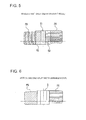
FIG. 1] FIG. 1 is a schematic horizontal cross section of a vehicular headlamp, showing a best mode of the present invention together withFIGS. 2 to 9 . - [
FIG. 2] FIG. 2 is a schematic longitudinal cross section of the vehicular headlamp. - [
FIG. 3] FIG. 3 is a diagram showing each mode in a double lighting state. - [
FIG. 4] FIG. 4 is a diagram showing each mode in a single lighting state. - [
FIG. 5] FIG. 5 is a diagram showing the state of a first split width variable mode in the double lighting state. - [
FIG. 6] FIG. 6 is a diagram showing the state of a second split width variable mode in the single lighting state. - [
FIG. 7] FIG. 7 shows cross-sectional views showing other examples of a reflective body. - [
FIG. 8] FIG. 8 is a diagram showing a light distribution pattern that is formed when a low beam is radiated in a state in which a split is formed. - [
FIG. 9] FIG. 9 is a diagram showing each mode in the case where one light source is provided. - Hereinafter, a best mode for carrying out a vehicular headlamp according to the present invention will be described with reference to accompanying drawings.
- A
vehicular headlamp 1 is disposed at each of both right and left ends of a vehicle body. As shown inFIGS. 1 and2 , thevehicular headlamp 1 includes alamp housing 2 having a recess that opens forward, and acover 3 closing the open face of thelamp housing 2, and a lampouter casing 4 is formed by thelamp housing 2 and thecover 3. The inside of the lampouter casing 4 is formed as alamp chamber 5. - A
lamp unit 6 is disposed in thelamp chamber 5. Thelamp unit 6 is a so-called high beam lamp unit for irradiating a distant location. Thelamp unit 6 is tiltably supported in thelamp housing 2 by an optical axis adjustment mechanism, not shown. - The
lamp unit 6 is a so-called projector type lamp unit havinglight sources projection lens 8, alens holder 9, ashade 10, andreflectors - The
light sources light sources light sources - The
projection lens 8 is formed in, e.g., a generally hemispherical shape that protrudes forward. - The
lens holder 9 is formed in a cylindrical shape. The outer periphery of theprojection lens 8 is attached to the front end face of thelens holder 9, so that theprojection lens 8 is held by thelens holder 9. - The
shade 10 is formed in, e.g., a plate shape that faces the longitudinal direction, and has a function to block part of light emitted from thelight sources - The
reflectors lens holder 9, and are disposed continuously in the lateral direction. The inner surfaces of thereflectors reflective surfaces - A
reflective body 12 is disposed between theprojection lens 8 and thelight sources lamp unit 6, and thereflective body 12 is movable in the lateral direction. In thelamp unit 6, the rear focal point of theprojection lens 8 is substantially matched with the focal point of thereflectors reflective body 12 is located near the matched focal point when positioned in the central portion of its moving range. Thereflective body 12 is moved in the lateral direction along a linear or gentle arc-shaped trajectory. - The
reflective body 12 is formed in the shape of, e.g., a vertically elongated block (a rectangular parallelepiped), and both right and left side surfaces thereof are formed asreflective surfaces - When light is emitted from the
light sources lamp unit 6, the emitted light is reflected by the lightreflective surfaces reflectors projection lens 8 and thecover 3 and radiated in the forward direction. At this time, part of the light is blocked by theshade 10. - Moreover, at this time, the light emitted from the
light sources reflective body 12, depending on the position of thereflective body 12. Of the light emitted from thelight sources reflective body 12 is blocked, whereas the light that has reached thereflective surfaces reflective surfaces lamp unit 6, a light distribution pattern is varied according to the position of thereflective body 12. - The following two lighting states can be set in the lamp unit 6: a double lighting state in which the two
light sources light sources 7 is lit and the otherlight source 7 is not lit. - The light distribution patterns that are formed when light is emitted from the
light sources vehicular headlamps FIGS. 3 and4 ). - The
lamp units vehicular headlamps light sources lamp unit 6. Light emitted from thelight sources vehicular headlamp 1 and light emitted from thelight sources vehicular headlamp 1 are superposed on each other at a forward position, and a light distribution pattern is formed by the superposed light. - In the
lamp units reflective bodies - A vehicle having the
vehicular headlamps reflective bodies reflective bodies light sources reflective bodies - First, the light distribution patterns in each mode of the double lighting state will be described (see
FIG. 3 ). Note that in the following description,light sources light sources light sources -
Mode 1 is a full radiation mode in which no light is blocked by thereflective bodies - In
mode 1, eachreflective body light sources reflective bodies light sources light sources -
Mode 2 is a first center split mode in which light heading toward the central portion in the lateral direction of the irradiation region is blocked by thereflective bodies - In
mode 2, eachreflective body light sources reflective bodies light sources light sources reflective bodies - For example, a preceding vehicle, an oncoming vehicle, or the like is present in the split region S at this time, and generation of glare light to the preceding vehicle, the oncoming vehicle, or the like is prevented.
- Of the light emitted from the
light sources reflective surfaces reflective bodies reflective surfaces reflective surfaces reflective bodies reflective surfaces -
Mode 3 is a first right split mode in which part of light heading rightward in the irradiation region is blocked by thereflective bodies - In
mode 3, eachreflective body light sources reflective bodies light sources reflective bodies reflective bodies - For example, a preceding vehicle, an oncoming vehicle, or the like is present in the split region S at this time, and generation of glare light to the preceding vehicle, the oncoming vehicle, or the like is prevented.
-
Mode 4 is a first left split mode in which part of light heading leftward in the irradiation region is blocked by thereflective bodies - In
mode 4, eachreflective body light sources reflective bodies light sources reflective bodies reflective bodies - For example, a preceding vehicle, an oncoming vehicle, or the like is present in the split region S at this time, and generation of glare light to the preceding vehicle, the oncoming vehicle, or the like is prevented.
-
Mode 5 is a first split width variable mode in which part of light heading rightward in the irradiation region and part of light heading leftward in the irradiation region are blocked by thereflective bodies - In
mode 5, thereflective bodies reflective bodies 12 is positioned on the left side of the center of the light passing region, and the otherreflective body 12 is positioned on the right side of the center of the light passing region, so that part of light emitted from thelight sources reflective bodies light source 7A of one of thelamp units 6, the light in the right end portion is blocked by one of thereflective bodies 12. Of the light emitted from thelight source 7B of theother lamp unit 6, the light in the left end portion is blocked by the otherreflective body 12. Thus, asplit region S 1 is formed in the central portion of the irradiation region (seeFIG. 5 ). - Split regions S2, S2 are formed on the left and right sides of the split region S1, respectively. The split regions S2, S2 are the regions that are formed by blocking the light emitted from one of the
light sources 7A and the light emitted from the otherlight source 7B by thereflective bodies light sources 7B and the light emitted from the otherlight source 7A. Thus, the split regions S2, S2 are the regions having lower luminance than that in the irradiation region PA formed by superposing the light beams emitted from thelight sources light sources - The widths of the split regions S1, S2, S2 are varied according to the positions to which the
reflective bodies - For example, a preceding vehicle, an oncoming vehicle, or the like is present in the split regions S1, S2, S2 at this time, and generation of glare light to the preceding vehicle, the oncoming vehicle, or the like is prevented.
- The light distribution patterns in each mode of the single lighting state will be described below (see
FIG. 4 ). Note that in the following description,light sources 7A. 7B represent the twolight sources light sources - Mode 6-1 is a second center split mode in which light heading toward the central portion in the lateral direction of the irradiation region is blocked by the
reflective bodies - In mode 6-1, each
reflective body light sources reflective bodies light sources light sources reflective bodies - For example, a preceding vehicle, an oncoming vehicle, or the like is present in the split region S at this time, and generation of glare light to the preceding vehicle, the oncoming vehicle, or the like is prevented.
- Mode 6-2 is a second center split mode in which light heading toward the central portion in the lateral direction of the irradiation region is blocked by the
reflective bodies - In mode 6-2, each
reflective body light sources reflective bodies light sources light sources reflective bodies - For example, a preceding vehicle, an oncoming vehicle, or the like is present in the split region S at this time, and generation of glare light to the preceding vehicle, the oncoming vehicle, or the like is prevented
-
Mode 7 is a second right split mode in which light heading rightward in the irradiation region is blocked by thereflective bodies - In
mode 7, eachreflective body light sources reflective bodies light sources light sources reflective bodies reflective bodies - For example, a preceding vehicle, an oncoming vehicle, or the like is present in the split region S at this time, and generation of glare light to the preceding vehicle, the oncoming vehicle, or the like is prevented.
-
Mode 8 is a second left split mode in which light heading leftward in the irradiation region is blocked by thereflective bodies - In
mode 8, eachreflective body light sources reflective bodies light sources light sources reflective bodies reflective bodies - For example, a preceding vehicle, an oncoming vehicle, or the like is present in the split region S at this time, and generation of glare light to the preceding vehicle, the oncoming vehicle, or the like is prevented.
-
Mode 9 is a second split width variable mode in which part of light heading leftward in the irradiation region and part of light heading rightward in the irradiation region are blocked by thereflective bodies - In
mode 9, thereflective bodies reflective bodies 12 is positioned on the right side of the center of the light passing region, and the otherreflective body 12 is positioned on the left side of the center of the light passing region, so that part of light emitted from thelight sources reflective bodies light sources 7A and the otherlight source 7B are unlit. Of the light emitted from thelight source 7B of one of thelamp units 6, the light in the left end portion is blocked by one of thereflective bodies 12. Of the light emitted from thelight source 7A of theother lamp unit 6, the light in the right end portion is blocked by the otherreflective body 12. Thus, a wide split region S is formed in the central portion of the irradiation region (seeFIG. 6 ). The width of the split region S is varied according to the positions to which thereflective bodies - For example, a preceding vehicle, an oncoming vehicle, or the like is present in the split region S at this time, and generation of glare light to the preceding vehicle, the oncoming vehicle, or the like is prevented.
- As described above, each
vehicular headlamp 1 is configured so as to form a desired light distribution pattern by blocking light by thereflective body 12 that is movable in the lateral direction, and is not configured so that the irradiation region is divided and the same number of light sources as that of irradiation regions is disposed. This can reduce the number oflight sources 7, and thus can reduce the manufacturing cost. - Moreover, since a required light distribution pattern can be formed according to the position to which the
reflective body 12 is moved, the size and position of the irradiation region can be arbitrarily changed, and an optimal radiation state can be attained according to the position where a preceding vehicle or an oncoming vehicle is present, whereby generation of glare light can be prevented. - Furthermore, light reflected by the
reflective surfaces reflective body 12 is superposed on light radiated in the forward direction without reaching thereflective surfaces reflective body 12. Thus, luminance of the light that is radiated in the forward direction can be increased accordingly. - Moreover, since the two
light sources reflectors vehicular headlamp 1, the number of different kinds of light distribution patterns can be increased, whereby the degree of freedom of light distribution control can be increased. - In addition, by synchronously moving the
reflective bodies lamp unit vehicular headlamps - Note that although the
reflective bodies 12 formed in the shape of a block are described above as an example, thereflective bodies 12 may have other shape as long as they have thereflective surfaces FIG. 7 , thereflective bodies 12 may have a U-shape, a trapezoidal shape, an H-shape, a V-shape, or the like, which opens forward or rearward in a horizontal cross section. - As described above, although the
lamp unit 6 provided in thevehicular headlamp 1 is a high beam lamp unit for radiating a distant location, the vehicle is provided also with a low beam lamp unit for radiating a nearby location. When light is radiated from the high beam lamp unit, light is also radiated from the low beam lamp unit. - Light a, α radiated from the high
beam lamp unit 6 is superposed on part of light β emitted from the low beam lamp unit at a position near a horizontal cutline H (seeFIG. 8 ). In the case where the split S is formed in the light distribution pattern at this time, a portion βp between superposed portions αp, αp appears dark because the portions αp, αp are present on the right and left sides of the portion βp. - Thus, in the
vehicular headlamp 1, thereflective body 12 is made movable in the vertical direction in addition to the lateral direction so that the part βp does not appear dark (seeFIG. 2 ). - That is, by moving the
reflective body 12 to a position below theshade 10, a space B through which light A radiated to the part βp passes is formed between theshade 10 and thereflective body 12, and the light A that has passed through the space B is superposed on the part βp so that the part βp does not appear dark. - Since the
reflective body 12 is thus movable in the vertical direction, light can be emitted to a required irradiation region, and luminance can be increased. - Note that in the case where the
reflective body 12 is movable in the vertical direction, the upper surface of thereflective body 12 may be formed as an upperreflective surface 12b. By forming the upper surface of thereflective body 12 as the upperreflective surface 12b, light reflected by the upperreflective surface 12b passes between theshade 10 and thereflective body 12, and is radiated in the forward direction. Thus, the luminance can further be increased. - Although an example in which two
light sources reflectors lamp unit 6 is described above, the number oflight sources 7 and the number ofreflectors 11 are not limited to two, and any number oflight sources 7 and any number ofreflectors 11 may be disposed. - Light distribution patterns that are formed when light is emitted from lamp units each having one
light source 7 will be described below as an example (seeFIG. 9 ). - Light emitted from the
light source 7 of the rightvehicular headlamp 1 and light emitted from thelight source 7 of the leftvehicular headlamp 1 are superposed on each other at a forward position, and a light distribution pattern is formed by the superposed light. Thereflective bodies - Since a light distribution pattern that is formed by light emitted from the
light source 7 of the rightvehicular headlamp 1 is the same as a light distribution pattern that is formed by light emitted from thelight source 7 of the leftvehicular headlamp 1, only the states and the light distribution patterns of one of the lamp units are shown inFIG. 9 . - Mode 1A is a full radiation mode in which no light is blocked by the
reflective bodies - In mode 1A, each
reflective body light sources reflective bodies - Mode 2A is a center split mode in which light heading toward the central portion in the lateral direction of the irradiation region is blocked by the
reflective bodies - In mode 2A, each
reflective body light sources reflective bodies - For example, a preceding vehicle, an oncoming vehicle, or the like is present in the split region S at this time, and generation of glare light to the preceding vehicle, the oncoming vehicle, or the like is prevented.
- Mode 3A is a right split mode in which part of light heading rightward in the irradiation region is blocked by the
reflective bodies - In mode 3A, each
reflective body light sources reflective bodies reflective bodies - For example, a preceding vehicle, an oncoming vehicle, or the like is present in the split region S at this time, and generation of glare light to the preceding vehicle, the oncoming vehicle, or the like is prevented.
- Mode 4A is a left split mode in which part of light heading leftward in the irradiation region is blocked by the
reflective bodies - In mode 4A, each
reflective body light sources reflective bodies reflective bodies - For example, a preceding vehicle, an oncoming vehicle, or the like is present in the split region S at this time, and generation of glare light to the preceding vehicle, the oncoming vehicle, or the like is prevented.
- The shape and structure of each part in the above best mode are merely shown as an example of embodiment that is performed when carrying out the present invention, and should not be construed as limiting the technical scope of the present invention.
-
- 1
- VEHICULAR HEADLAMP
- 2
- LAMP HOUSING
- 3
- COVER
- 4
- LAMP OUTER CASING
- 6
- LAMP UNIT
- 7
- LIGHT SOURCE
- 8
- PROJECTION LENS
- 11
- REFLECTOR
- 12
- REFLECTIVE BODY
- 12a
- REFLECTIVE SURFACE
- 12b
- UPPER REFLECTIVE SURFACE
Claims (5)
- A vehicular headlamp, in which a lamp unit is disposed inside a lamp outer casing formed by a cover and a housing, the vehicular headlamp characterized in that
the lamp unit includes
a light source for emitting light,
a reflector for reflecting, in a forward direction, light emitted from the light source, a projection lens for projecting the light emitted from the light source to radiate the light in the forward direction, and
a reflective body that has a pair of reflective surfaces facing substantially a lateral direction, is located between the light source and the projection lens, and is movable in the lateral direction. - The vehicular headlamp according to claim 1, characterized in that
the light source is disposed as two light sources so as to be spaced apart from each other in the lateral direction, and
the reflector for reflecting, in the forward direction, the light emitted from the respective light sources is disposed as two reflectors continuously in the lateral direction. - The vehicular headlamp according to claim 1 or 2, characterized in that:a shade for blocking the light emitted from the light source is provided, and the reflective body is movable in a vertical direction with respect to the shade.
- The vehicular headlamp according to claim 3, characterized in that
an upper surface of the reflective body is formed as an upper reflective surface. - The vehicular headlamp according to claim 1, 2, 3, or 4, characterized in that
the lamp outer casing and the lamp unit are disposed at each of both right and left ends of a vehicle body, and
the reflective body of the left lamp unit and the reflective body of the right lamp unit are moved synchronously.
Applications Claiming Priority (1)
| Application Number | Priority Date | Filing Date | Title |
|---|---|---|---|
| JP2010024197A JP5513915B2 (en) | 2010-02-05 | 2010-02-05 | Vehicle headlamp |
Publications (2)
| Publication Number | Publication Date |
|---|---|
| EP2354644A1 true EP2354644A1 (en) | 2011-08-10 |
| EP2354644B1 EP2354644B1 (en) | 2015-01-07 |
Family
ID=43927083
Family Applications (1)
| Application Number | Title | Priority Date | Filing Date |
|---|---|---|---|
| EP11152662.0A Not-in-force EP2354644B1 (en) | 2010-02-05 | 2011-01-31 | Vehicular headlamp |
Country Status (2)
| Country | Link |
|---|---|
| EP (1) | EP2354644B1 (en) |
| JP (1) | JP5513915B2 (en) |
Cited By (4)
| Publication number | Priority date | Publication date | Assignee | Title |
|---|---|---|---|---|
| EP2565530A1 (en) | 2011-09-05 | 2013-03-06 | Valeo Vision | Optical module for a signalling and/or lighting device |
| CN103216778A (en) * | 2012-01-24 | 2013-07-24 | 株式会社小糸制作所 | Lighting unit and vehicular lighting apparatus |
| FR3025151A1 (en) * | 2014-08-29 | 2016-03-04 | Valeo Vision | METHOD FOR CONTROLLING A BRIGHT BEAM AND LIGHTING AND / OR SIGNALING MODULE THEREOF |
| EP3343094A1 (en) * | 2016-12-27 | 2018-07-04 | Lg Electronics Inc. | Lamp for vehicle and method for controlling the same |
Citations (4)
| Publication number | Priority date | Publication date | Assignee | Title |
|---|---|---|---|---|
| DE1167773B (en) * | 1962-11-03 | 1964-04-16 | Dr Med Dent Walter Ott | Headlights, especially for motor vehicles |
| GB1212231A (en) * | 1967-02-28 | 1970-11-11 | Cibie Projecteurs | A headlight beam-deflector device |
| US5060120A (en) * | 1990-04-19 | 1991-10-22 | Koito Manufacturing Co., Ltd. | Variable distribution type automotive headlamp |
| JP2007179969A (en) | 2005-12-28 | 2007-07-12 | Koito Mfg Co Ltd | Vehicle lamp |
Family Cites Families (3)
| Publication number | Priority date | Publication date | Assignee | Title |
|---|---|---|---|---|
| JPS62222507A (en) * | 1986-03-25 | 1987-09-30 | 市光工業株式会社 | Head lamp for vehicle |
| JP4459702B2 (en) * | 2004-04-27 | 2010-04-28 | 株式会社小糸製作所 | Lighting fixtures for vehicles |
| JP2007080606A (en) * | 2005-09-13 | 2007-03-29 | Koito Mfg Co Ltd | Lighting fixture unit of vehicular head-light |
-
2010
- 2010-02-05 JP JP2010024197A patent/JP5513915B2/en active Active
-
2011
- 2011-01-31 EP EP11152662.0A patent/EP2354644B1/en not_active Not-in-force
Patent Citations (4)
| Publication number | Priority date | Publication date | Assignee | Title |
|---|---|---|---|---|
| DE1167773B (en) * | 1962-11-03 | 1964-04-16 | Dr Med Dent Walter Ott | Headlights, especially for motor vehicles |
| GB1212231A (en) * | 1967-02-28 | 1970-11-11 | Cibie Projecteurs | A headlight beam-deflector device |
| US5060120A (en) * | 1990-04-19 | 1991-10-22 | Koito Manufacturing Co., Ltd. | Variable distribution type automotive headlamp |
| JP2007179969A (en) | 2005-12-28 | 2007-07-12 | Koito Mfg Co Ltd | Vehicle lamp |
Cited By (8)
| Publication number | Priority date | Publication date | Assignee | Title |
|---|---|---|---|---|
| EP2565530A1 (en) | 2011-09-05 | 2013-03-06 | Valeo Vision | Optical module for a signalling and/or lighting device |
| CN103216778A (en) * | 2012-01-24 | 2013-07-24 | 株式会社小糸制作所 | Lighting unit and vehicular lighting apparatus |
| US8939624B2 (en) | 2012-01-24 | 2015-01-27 | Koito Manufacturing Co., Ltd. | Lighting unit and vehicular lighting apparatus |
| FR3025151A1 (en) * | 2014-08-29 | 2016-03-04 | Valeo Vision | METHOD FOR CONTROLLING A BRIGHT BEAM AND LIGHTING AND / OR SIGNALING MODULE THEREOF |
| EP2990264A3 (en) * | 2014-08-29 | 2016-03-09 | Valeo Vision | Method for controlling a light beam and corresponding lighting and/or signalling module |
| EP3343094A1 (en) * | 2016-12-27 | 2018-07-04 | Lg Electronics Inc. | Lamp for vehicle and method for controlling the same |
| CN108613098A (en) * | 2016-12-27 | 2018-10-02 | Lg电子株式会社 | Vehicle lamp and its control method |
| CN108613098B (en) * | 2016-12-27 | 2021-12-03 | Zkw集团有限责任公司 | Vehicle lamp and control method thereof |
Also Published As
| Publication number | Publication date |
|---|---|
| EP2354644B1 (en) | 2015-01-07 |
| JP5513915B2 (en) | 2014-06-04 |
| JP2011165386A (en) | 2011-08-25 |
Similar Documents
| Publication | Publication Date | Title |
|---|---|---|
| EP2407710B1 (en) | Vehicle lamp | |
| EP2405187B1 (en) | Lamp unit | |
| CN107300145B (en) | Vehicle lamp and vehicle having the same | |
| US7234852B2 (en) | Vehicle headlamp | |
| JP4933434B2 (en) | LED collimator element with asymmetric collimator | |
| KR101315659B1 (en) | Vehicular lamp | |
| JP5828424B2 (en) | Vehicle headlamp | |
| JP6980377B2 (en) | Vehicle headlights | |
| CN112747287B (en) | Lighting device producing an arcuate light distribution | |
| US20120051071A1 (en) | Vehicle headlamp and vehicle headlamp apparatus | |
| US10393337B2 (en) | Vehicular headlamp | |
| CN108224352B (en) | Lamp fitting | |
| JP2019114425A (en) | Vehicular headlight | |
| JP6651797B2 (en) | Vehicle headlights | |
| JP2023535376A (en) | Two-way function optical system and method | |
| EP2354644B1 (en) | Vehicular headlamp | |
| JP5843332B2 (en) | Vehicle lamp | |
| WO2013118625A1 (en) | Lamp unit and vehicle lamp | |
| JP2018022572A (en) | Vehicular headlight | |
| CN111556945A (en) | Vehicle headlamp | |
| JP6627282B2 (en) | Vehicle headlights | |
| JP2016225210A (en) | Vehicle headlamp | |
| JP2024140476A (en) | Vehicle lighting fixtures |
Legal Events
| Date | Code | Title | Description |
|---|---|---|---|
| PUAI | Public reference made under article 153(3) epc to a published international application that has entered the european phase |
Free format text: ORIGINAL CODE: 0009012 |
|
| 17P | Request for examination filed |
Effective date: 20110131 |
|
| AK | Designated contracting states |
Kind code of ref document: A1 Designated state(s): AL AT BE BG CH CY CZ DE DK EE ES FI FR GB GR HR HU IE IS IT LI LT LU LV MC MK MT NL NO PL PT RO RS SE SI SK SM TR |
|
| AX | Request for extension of the european patent |
Extension state: BA ME |
|
| GRAP | Despatch of communication of intention to grant a patent |
Free format text: ORIGINAL CODE: EPIDOSNIGR1 |
|
| INTG | Intention to grant announced |
Effective date: 20140908 |
|
| GRAS | Grant fee paid |
Free format text: ORIGINAL CODE: EPIDOSNIGR3 |
|
| GRAA | (expected) grant |
Free format text: ORIGINAL CODE: 0009210 |
|
| AK | Designated contracting states |
Kind code of ref document: B1 Designated state(s): AL AT BE BG CH CY CZ DE DK EE ES FI FR GB GR HR HU IE IS IT LI LT LU LV MC MK MT NL NO PL PT RO RS SE SI SK SM TR |
|
| REG | Reference to a national code |
Ref country code: GB Ref legal event code: FG4D |
|
| REG | Reference to a national code |
Ref country code: CH Ref legal event code: EP |
|
| REG | Reference to a national code |
Ref country code: IE Ref legal event code: FG4D |
|
| REG | Reference to a national code |
Ref country code: AT Ref legal event code: REF Ref document number: 705985 Country of ref document: AT Kind code of ref document: T Effective date: 20150215 |
|
| REG | Reference to a national code |
Ref country code: DE Ref legal event code: R096 Ref document number: 602011012811 Country of ref document: DE Effective date: 20150219 |
|
| REG | Reference to a national code |
Ref country code: NL Ref legal event code: VDEP Effective date: 20150107 |
|
| PGFP | Annual fee paid to national office [announced via postgrant information from national office to epo] |
Ref country code: GB Payment date: 20150128 Year of fee payment: 5 |
|
| REG | Reference to a national code |
Ref country code: AT Ref legal event code: MK05 Ref document number: 705985 Country of ref document: AT Kind code of ref document: T Effective date: 20150107 |
|
| REG | Reference to a national code |
Ref country code: LT Ref legal event code: MG4D |
|
| PG25 | Lapsed in a contracting state [announced via postgrant information from national office to epo] |
Ref country code: BE Free format text: LAPSE BECAUSE OF NON-PAYMENT OF DUE FEES Effective date: 20150131 |
|
| PG25 | Lapsed in a contracting state [announced via postgrant information from national office to epo] |
Ref country code: LT Free format text: LAPSE BECAUSE OF FAILURE TO SUBMIT A TRANSLATION OF THE DESCRIPTION OR TO PAY THE FEE WITHIN THE PRESCRIBED TIME-LIMIT Effective date: 20150107 Ref country code: FI Free format text: LAPSE BECAUSE OF FAILURE TO SUBMIT A TRANSLATION OF THE DESCRIPTION OR TO PAY THE FEE WITHIN THE PRESCRIBED TIME-LIMIT Effective date: 20150107 Ref country code: HR Free format text: LAPSE BECAUSE OF FAILURE TO SUBMIT A TRANSLATION OF THE DESCRIPTION OR TO PAY THE FEE WITHIN THE PRESCRIBED TIME-LIMIT Effective date: 20150107 Ref country code: ES Free format text: LAPSE BECAUSE OF FAILURE TO SUBMIT A TRANSLATION OF THE DESCRIPTION OR TO PAY THE FEE WITHIN THE PRESCRIBED TIME-LIMIT Effective date: 20150107 Ref country code: NO Free format text: LAPSE BECAUSE OF FAILURE TO SUBMIT A TRANSLATION OF THE DESCRIPTION OR TO PAY THE FEE WITHIN THE PRESCRIBED TIME-LIMIT Effective date: 20150407 Ref country code: SE Free format text: LAPSE BECAUSE OF FAILURE TO SUBMIT A TRANSLATION OF THE DESCRIPTION OR TO PAY THE FEE WITHIN THE PRESCRIBED TIME-LIMIT Effective date: 20150107 Ref country code: BG Free format text: LAPSE BECAUSE OF FAILURE TO SUBMIT A TRANSLATION OF THE DESCRIPTION OR TO PAY THE FEE WITHIN THE PRESCRIBED TIME-LIMIT Effective date: 20150407 |
|
| REG | Reference to a national code |
Ref country code: CH Ref legal event code: PL |
|
| PG25 | Lapsed in a contracting state [announced via postgrant information from national office to epo] |
Ref country code: IS Free format text: LAPSE BECAUSE OF FAILURE TO SUBMIT A TRANSLATION OF THE DESCRIPTION OR TO PAY THE FEE WITHIN THE PRESCRIBED TIME-LIMIT Effective date: 20150507 Ref country code: LV Free format text: LAPSE BECAUSE OF FAILURE TO SUBMIT A TRANSLATION OF THE DESCRIPTION OR TO PAY THE FEE WITHIN THE PRESCRIBED TIME-LIMIT Effective date: 20150107 Ref country code: PL Free format text: LAPSE BECAUSE OF FAILURE TO SUBMIT A TRANSLATION OF THE DESCRIPTION OR TO PAY THE FEE WITHIN THE PRESCRIBED TIME-LIMIT Effective date: 20150107 Ref country code: AT Free format text: LAPSE BECAUSE OF FAILURE TO SUBMIT A TRANSLATION OF THE DESCRIPTION OR TO PAY THE FEE WITHIN THE PRESCRIBED TIME-LIMIT Effective date: 20150107 Ref country code: NL Free format text: LAPSE BECAUSE OF FAILURE TO SUBMIT A TRANSLATION OF THE DESCRIPTION OR TO PAY THE FEE WITHIN THE PRESCRIBED TIME-LIMIT Effective date: 20150107 Ref country code: RS Free format text: LAPSE BECAUSE OF FAILURE TO SUBMIT A TRANSLATION OF THE DESCRIPTION OR TO PAY THE FEE WITHIN THE PRESCRIBED TIME-LIMIT Effective date: 20150107 Ref country code: GR Free format text: LAPSE BECAUSE OF FAILURE TO SUBMIT A TRANSLATION OF THE DESCRIPTION OR TO PAY THE FEE WITHIN THE PRESCRIBED TIME-LIMIT Effective date: 20150408 |
|
| REG | Reference to a national code |
Ref country code: DE Ref legal event code: R097 Ref document number: 602011012811 Country of ref document: DE |
|
| PG25 | Lapsed in a contracting state [announced via postgrant information from national office to epo] |
Ref country code: RO Free format text: LAPSE BECAUSE OF FAILURE TO SUBMIT A TRANSLATION OF THE DESCRIPTION OR TO PAY THE FEE WITHIN THE PRESCRIBED TIME-LIMIT Effective date: 20150107 Ref country code: DK Free format text: LAPSE BECAUSE OF FAILURE TO SUBMIT A TRANSLATION OF THE DESCRIPTION OR TO PAY THE FEE WITHIN THE PRESCRIBED TIME-LIMIT Effective date: 20150107 Ref country code: LI Free format text: LAPSE BECAUSE OF NON-PAYMENT OF DUE FEES Effective date: 20150131 Ref country code: CH Free format text: LAPSE BECAUSE OF NON-PAYMENT OF DUE FEES Effective date: 20150131 Ref country code: SK Free format text: LAPSE BECAUSE OF FAILURE TO SUBMIT A TRANSLATION OF THE DESCRIPTION OR TO PAY THE FEE WITHIN THE PRESCRIBED TIME-LIMIT Effective date: 20150107 Ref country code: CZ Free format text: LAPSE BECAUSE OF FAILURE TO SUBMIT A TRANSLATION OF THE DESCRIPTION OR TO PAY THE FEE WITHIN THE PRESCRIBED TIME-LIMIT Effective date: 20150107 Ref country code: EE Free format text: LAPSE BECAUSE OF FAILURE TO SUBMIT A TRANSLATION OF THE DESCRIPTION OR TO PAY THE FEE WITHIN THE PRESCRIBED TIME-LIMIT Effective date: 20150107 Ref country code: MC Free format text: LAPSE BECAUSE OF FAILURE TO SUBMIT A TRANSLATION OF THE DESCRIPTION OR TO PAY THE FEE WITHIN THE PRESCRIBED TIME-LIMIT Effective date: 20150107 |
|
| REG | Reference to a national code |
Ref country code: IE Ref legal event code: MM4A |
|
| PLBE | No opposition filed within time limit |
Free format text: ORIGINAL CODE: 0009261 |
|
| STAA | Information on the status of an ep patent application or granted ep patent |
Free format text: STATUS: NO OPPOSITION FILED WITHIN TIME LIMIT |
|
| REG | Reference to a national code |
Ref country code: FR Ref legal event code: PLFP Year of fee payment: 6 |
|
| 26N | No opposition filed |
Effective date: 20151008 |
|
| PG25 | Lapsed in a contracting state [announced via postgrant information from national office to epo] |
Ref country code: IT Free format text: LAPSE BECAUSE OF FAILURE TO SUBMIT A TRANSLATION OF THE DESCRIPTION OR TO PAY THE FEE WITHIN THE PRESCRIBED TIME-LIMIT Effective date: 20150107 |
|
| PG25 | Lapsed in a contracting state [announced via postgrant information from national office to epo] |
Ref country code: IE Free format text: LAPSE BECAUSE OF NON-PAYMENT OF DUE FEES Effective date: 20150131 |
|
| PG25 | Lapsed in a contracting state [announced via postgrant information from national office to epo] |
Ref country code: SI Free format text: LAPSE BECAUSE OF FAILURE TO SUBMIT A TRANSLATION OF THE DESCRIPTION OR TO PAY THE FEE WITHIN THE PRESCRIBED TIME-LIMIT Effective date: 20150107 |
|
| PG25 | Lapsed in a contracting state [announced via postgrant information from national office to epo] |
Ref country code: BE Free format text: LAPSE BECAUSE OF FAILURE TO SUBMIT A TRANSLATION OF THE DESCRIPTION OR TO PAY THE FEE WITHIN THE PRESCRIBED TIME-LIMIT Effective date: 20150107 |
|
| GBPC | Gb: european patent ceased through non-payment of renewal fee |
Effective date: 20160131 |
|
| PG25 | Lapsed in a contracting state [announced via postgrant information from national office to epo] |
Ref country code: GB Free format text: LAPSE BECAUSE OF NON-PAYMENT OF DUE FEES Effective date: 20160131 |
|
| REG | Reference to a national code |
Ref country code: FR Ref legal event code: PLFP Year of fee payment: 7 |
|
| PG25 | Lapsed in a contracting state [announced via postgrant information from national office to epo] |
Ref country code: MT Free format text: LAPSE BECAUSE OF FAILURE TO SUBMIT A TRANSLATION OF THE DESCRIPTION OR TO PAY THE FEE WITHIN THE PRESCRIBED TIME-LIMIT Effective date: 20150107 |
|
| PG25 | Lapsed in a contracting state [announced via postgrant information from national office to epo] |
Ref country code: SM Free format text: LAPSE BECAUSE OF FAILURE TO SUBMIT A TRANSLATION OF THE DESCRIPTION OR TO PAY THE FEE WITHIN THE PRESCRIBED TIME-LIMIT Effective date: 20150107 Ref country code: HU Free format text: LAPSE BECAUSE OF FAILURE TO SUBMIT A TRANSLATION OF THE DESCRIPTION OR TO PAY THE FEE WITHIN THE PRESCRIBED TIME-LIMIT; INVALID AB INITIO Effective date: 20110131 |
|
| PG25 | Lapsed in a contracting state [announced via postgrant information from national office to epo] |
Ref country code: CY Free format text: LAPSE BECAUSE OF FAILURE TO SUBMIT A TRANSLATION OF THE DESCRIPTION OR TO PAY THE FEE WITHIN THE PRESCRIBED TIME-LIMIT Effective date: 20150107 |
|
| PG25 | Lapsed in a contracting state [announced via postgrant information from national office to epo] |
Ref country code: PT Free format text: LAPSE BECAUSE OF FAILURE TO SUBMIT A TRANSLATION OF THE DESCRIPTION OR TO PAY THE FEE WITHIN THE PRESCRIBED TIME-LIMIT Effective date: 20150507 |
|
| PG25 | Lapsed in a contracting state [announced via postgrant information from national office to epo] |
Ref country code: TR Free format text: LAPSE BECAUSE OF FAILURE TO SUBMIT A TRANSLATION OF THE DESCRIPTION OR TO PAY THE FEE WITHIN THE PRESCRIBED TIME-LIMIT Effective date: 20150107 |
|
| PG25 | Lapsed in a contracting state [announced via postgrant information from national office to epo] |
Ref country code: LU Free format text: LAPSE BECAUSE OF NON-PAYMENT OF DUE FEES Effective date: 20150131 |
|
| REG | Reference to a national code |
Ref country code: FR Ref legal event code: PLFP Year of fee payment: 8 |
|
| PG25 | Lapsed in a contracting state [announced via postgrant information from national office to epo] |
Ref country code: MK Free format text: LAPSE BECAUSE OF FAILURE TO SUBMIT A TRANSLATION OF THE DESCRIPTION OR TO PAY THE FEE WITHIN THE PRESCRIBED TIME-LIMIT Effective date: 20150107 |
|
| PG25 | Lapsed in a contracting state [announced via postgrant information from national office to epo] |
Ref country code: AL Free format text: LAPSE BECAUSE OF FAILURE TO SUBMIT A TRANSLATION OF THE DESCRIPTION OR TO PAY THE FEE WITHIN THE PRESCRIBED TIME-LIMIT Effective date: 20150107 |
|
| PGFP | Annual fee paid to national office [announced via postgrant information from national office to epo] |
Ref country code: FR Payment date: 20181213 Year of fee payment: 9 |
|
| PGFP | Annual fee paid to national office [announced via postgrant information from national office to epo] |
Ref country code: DE Payment date: 20190115 Year of fee payment: 9 |
|
| REG | Reference to a national code |
Ref country code: DE Ref legal event code: R119 Ref document number: 602011012811 Country of ref document: DE |
|
| PG25 | Lapsed in a contracting state [announced via postgrant information from national office to epo] |
Ref country code: DE Free format text: LAPSE BECAUSE OF NON-PAYMENT OF DUE FEES Effective date: 20200801 Ref country code: FR Free format text: LAPSE BECAUSE OF NON-PAYMENT OF DUE FEES Effective date: 20200131 |