EP2354565A1 - Modular pliers for arranging technical furniture, protection and/or delimitation structures - Google Patents
Modular pliers for arranging technical furniture, protection and/or delimitation structures Download PDFInfo
- Publication number
- EP2354565A1 EP2354565A1 EP10425356A EP10425356A EP2354565A1 EP 2354565 A1 EP2354565 A1 EP 2354565A1 EP 10425356 A EP10425356 A EP 10425356A EP 10425356 A EP10425356 A EP 10425356A EP 2354565 A1 EP2354565 A1 EP 2354565A1
- Authority
- EP
- European Patent Office
- Prior art keywords
- pliers
- shaped jaws
- rear block
- screw
- base sector
- Prior art date
- Legal status (The legal status is an assumption and is not a legal conclusion. Google has not performed a legal analysis and makes no representation as to the accuracy of the status listed.)
- Granted
Links
- 238000004519 manufacturing process Methods 0.000 claims description 10
- 238000010276 construction Methods 0.000 description 5
- 239000011521 glass Substances 0.000 description 4
- 238000007726 management method Methods 0.000 description 3
- 238000000034 method Methods 0.000 description 3
- 230000000670 limiting effect Effects 0.000 description 2
- 239000000463 material Substances 0.000 description 2
- 238000005192 partition Methods 0.000 description 2
- 229910000831 Steel Inorganic materials 0.000 description 1
- 230000015572 biosynthetic process Effects 0.000 description 1
- 230000001419 dependent effect Effects 0.000 description 1
- 230000009977 dual effect Effects 0.000 description 1
- 230000000694 effects Effects 0.000 description 1
- 230000002452 interceptive effect Effects 0.000 description 1
- 239000007769 metal material Substances 0.000 description 1
- 230000035755 proliferation Effects 0.000 description 1
- 239000010959 steel Substances 0.000 description 1
- 239000000126 substance Substances 0.000 description 1
- 238000012384 transportation and delivery Methods 0.000 description 1
Images

Classifications
-
- F—MECHANICAL ENGINEERING; LIGHTING; HEATING; WEAPONS; BLASTING
- F16—ENGINEERING ELEMENTS AND UNITS; GENERAL MEASURES FOR PRODUCING AND MAINTAINING EFFECTIVE FUNCTIONING OF MACHINES OR INSTALLATIONS; THERMAL INSULATION IN GENERAL
- F16B—DEVICES FOR FASTENING OR SECURING CONSTRUCTIONAL ELEMENTS OR MACHINE PARTS TOGETHER, e.g. NAILS, BOLTS, CIRCLIPS, CLAMPS, CLIPS OR WEDGES; JOINTS OR JOINTING
- F16B2/00—Friction-grip releasable fastenings
- F16B2/02—Clamps, i.e. with gripping action effected by positive means other than the inherent resistance to deformation of the material of the fastening
- F16B2/06—Clamps, i.e. with gripping action effected by positive means other than the inherent resistance to deformation of the material of the fastening external, i.e. with contracting action
- F16B2/065—Clamps, i.e. with gripping action effected by positive means other than the inherent resistance to deformation of the material of the fastening external, i.e. with contracting action using screw-thread elements
Definitions
- the present invention concerns universal use modular pliers for arranging technical furniture, protection and/or delimitation structures, such as for example panelling, partition walls, parapets, stairs banisters and similar, mounted in rooms of buildings of various kind.
- the aforesaid pliers are attached to the support uprights or columns, usually defining vertical directions and having quadrilateral or circular section, of the technical structure.
- the pliers house two prefixed portions of the perimetrical edge of inner slabs adjacent and side-by-side each other which contribute to the formation of the technical structure itself.
- the pliers fixed to the end uprights instead, house a prefixed portion of the perimetrical edge of sole terminal slab.
- the conventional constructive type nowadays more widespread provides to apply two pliers per upright, one at the top and one at the bottom, ensuring for each slab four anchor points to the bearing structural elements.
- each pliers of known type designed for the use concerned include a rear block which is firmly coupled with the side wall of a bearing structural element, such as exactly an upright, of the technical structure.
- the pliers also comprise a pair of shaped jaws associated with the rear block and placed opposite, facing and spaced apart each other in order to define at least one side seat communicating with the outside and adapted to house a perimetrical portion of a slab, made for example of satin or decorated glass, clamped between the shaped jaws themselves and belonging to the technical structure.
- one of the two shaped jaws is monolithic with the rear block, while the other shaped block is connected with the rear block through fastening means of the type per se known.
- Manufacturer's pliers catalogue so provides a specific rear block and, as a consequence, a special shaped jaws substantially for each of the thicknesses of the slab.
- pliers producers make available a large number of pliers which differ one from another in the shape and size of the component elements.
- the present invention aims to overcome the drawbacks of the state of the art just cited.
- primary purpose of the invention is to devise modular pliers for arranging technical furniture, protection and/or delimitation structures which can be produced with a degree of standardization greater than the known technique, when the thickness of the slab to be coupled with the bearing structural elements through the pliers themselves vary.
- main purpose of the invention is to allow the application of a slab, for example made of glass, of any thickness to bearing structural elements without the need to totally change the type of pliers suit for the purpose, as it currently happens instead.
- the invention allows for a certain degree of standardization in the production of pliers according to the variability of the thickness of the slabs which, through these pliers, are coupled with bearing structural elements in order to arrange technical furniture, protection and/or delimitation structures.
- the pliers of the invention are made of three pieces distinct and separated each other, that is the rear block and the two shaped jaws, removably coupled each other, in use conditions, through first fastening means.
- the task of following the variability of the thickness of the slabs is entirely left to the rear block, the only component of the pliers of the invention to be produced in multiple examples, as many the thicknesses of the commercial slabs are precisely, while the two shaped jaws remain always unchanged and can be combined with any type of rear block.
- the adjustment of the pliers of the invention to the type of slab of the technical structure is so delegated to the rear block, whose front surface, facing the side seat which houses the slab, has a width which can be adjusted during production to the various thicknesses of the slab.
- the shaped jaws present, instead, fixed profile and sizes and are interchangeable in order to fit to the different operative situations related to the variability of the thickness of the slab of the technical structure.
- the present invention allows to increase, compared to prior art, production efficiency related to the manufacture of pliers for arranging technical furniture, protection and/or delimitation structures.
- the invention limits, compared to the current state of the art, the number of components and, consequently, article codes related to pliers for arranging technical furniture, protection and/or delimitation structures, simplifying management of the finished goods warehouse referred to them, with special reference to the thickness of the slabs which, by means of the aforesaid pliers, are coupled with the bearing structural elements of the technical structures.
- the modular pliers of the invention are simple to be produced and applied to the bearing structural element of the technical structure to be arranged.
- the modular pliers of the invention are shown in exploded and partial view in figures 1-3 in which it is as a whole numbered with 1.
- the modular pliers 1 are mostly suitable for arranging a technical furniture, protection and/or delimitation structure, for simplicity not shown in the accompanying drawings and consisting of for example a stair banister or a partition wall of a room, including bearing structural elements, or uprights or columns, having a regular profile.
- modular pliers 1 comprise:
- the shaped jaws 3, 4 are two pieces distinct and separated each other and from the rear block 2 with which are firmly and removably coupled through first fastening means, overall indicated with 6.
- the modular pliers also include properly second fastening means, only partially visible in the attached figures where they are overall indicated with 7, provided for the stable connection of rear block 2 with the aforesaid bearing structural element.
- the rear block 2 consists of:
- the spacing tooth 9 is made in single body with the base sector 8 and presents a front surface 9a, facing the side seat 5, and two lateral surfaces 9b, 9c which define planes equal and parallel each other.
- the base sector 8 presents two outer walls 8c, 8d defining planes equal and parallel each other: a lower stretch 12 of the inner face 3a, 4a of the shaped jaws 3, 4 is placed close to such outer walls 8c, 8d.
- the first lateral face 8a of the base sector 8 presents, in this case, a concave profile in cross section, as the modular pliers 1 are properly suited to be coupled with uprights, usually with vertical axis, having a circular profile in cross section.
- the first lateral face of the base sector will present a linear profile, in cross section: the modular pliers of the invention will then be conveniently coupled with bearing structural elements, such as uprights or columns, having a square profile in cross section.
- the spacing tooth 9 presents a quadrilateral, in this case rectangular, profile in cross section and a width L which is varied during production depending on the thickness of the slab housed in the side seat 5 and clamped between the shaped jaws 3, 4.
- the width L of the spacing tooth 9 is substantially equal to the thickness of the slab housed in the side seat 5.
- the modular pliers of the invention adapts, therefore, to any thickness of the slab to be coupled with the bearing structural element, without intervening in any way on the constructive shape of the shaped jaws 3, 4.
- each of the shaped jaws 3, 4 presents a substantially semi-elliptical shaped profile in longitudinal section, as well apparent from figure 4 .
- the shaped jaws 3, 5 present inner faces 3a, 4a which define planes parallel to the planes defined by the respective outer faces 3b, 4b.
- each of the shaped jaws 3, 4 presents a longitudinal undercut 13, made in the inner face 3a, 4a starting from the lower edge 3c, 4c towards the central area of each of the shaped jaws 3, 4.
- the longitudinal undercut 13 defines the lower stretch 12, placed close to the respective outer walls 8c, 8d of the base sector 8, and a transverse wall 14 placed close to the second face 8b of the base sector 8 along each of the linear steps 10, 11.
- the aforesaid lower stretch 12 of the inner face 3a, 4a of each of the shaped jaws 3, 4 presents substantially the same height H of each of the outer walls 8c, 8d of the base sector 8.
- the first fastening means 6 include, as figures 1-4 highlights:
- each of the screws 21, 22 is of the flat countersunk head (TPS) 23 type, housed in an annular groove 24 made around the inlet 25 of the first nut screws 15, 16 and third nut screws 19, 20 in such a way as that the outer wall 23a of the flat countersunk head 23 is coplanar to the outer face 3b, 4b of the shaped jaws 3, 4.
- TPS flat countersunk head
- the first fastening means may include a number of first through nut screws and, therefore, of second and third nut screws, different from that one described above, with this number that could vary at will starting from one.
- the inner wall 27 delimiting the through opening 26 is preferably provided with an annular shoulder 28 which determines for the through opening 26 itself a change in diameter starting from such an intermediate zone 27a.
- the head of the screw means just cited is positioned close to the annular shoulder 28, thus resulting totally and advantageously housed into the largest diameter portion of the through opening 26.
- the screw means are completely contained and, therefore, hidden in the rear block 2, leading to the dual advantage of not interfering with the slab when house in the side seat 5 and positioned close to the front surface 9a of the spacing tooth 9 and not affect in any way the aesthetic effect of the technical structure as a whole.
- the modular pliers 1 comprise stiffening means, applied to the inner face 3a, 4a of both the shaped jaws 3, 4 in order to interpose between the spacing tooth 9 of the rear block 2 and the shaped jaws 3, 4.
- the stiffening means include, mainly, a pair of rubber gaskets 29, 30 fixed to the main section 31 of the inner face 3a, 4a of the respective shaped jaws 3, 4.
- the operator places the rear block 2 close to the side wall of such a bearing structural element, in the chosen and correct position for the final configuration of the entire technical structure in question.
- the operator firmly couples the shaped jaw 3 to the rear block 2 by engaging the screws 21 with the first through nut screws 15, 16 and partially with the second through nut screws 17, 18.
- the operator supports the edge of the slab onto the front surface 9a of the spacing tooth 9 and finally firmly coupled with the rear block 2 even the other shaped jaw 4, as done for the shaped jaw 3.
- the slab of the technical structure is thus contained in the side seat 5, clamped between the shaped jaws 3, 4 of the modular pliers 1 just placed in their final operative configuration.
- the operator replaces only the rear block 2 with another one comprising a spacing tooth 9 having width L greater or lower than the rear block 2 just used, such a width L depending on the new thickness of the new slab to be coupled with the structural element of the technical structure.
- the modular pliers of the invention will be properly fixed to a bearing structural element (upright or column) placed in inner zones of the technical structure.
Landscapes
- Engineering & Computer Science (AREA)
- General Engineering & Computer Science (AREA)
- Mechanical Engineering (AREA)
- Furniture Connections (AREA)
- Compositions Of Macromolecular Compounds (AREA)
Abstract
Description
- The present invention concerns universal use modular pliers for arranging technical furniture, protection and/or delimitation structures, such as for example panelling, partition walls, parapets, stairs banisters and similar, mounted in rooms of buildings of various kind.
- It is known that some technical structures currently installed in buildings for the purposes of furniture, protection and/or delimitation, in general, include a plurality of panels or slabs, even made of aesthetic value materials and provided with a thickness of a certain importance, for example glass, rigidly interconnected each other by a plurality of specific pliers, usually made of metallic material, such as satin steel.
- The aforesaid pliers are attached to the support uprights or columns, usually defining vertical directions and having quadrilateral or circular section, of the technical structure.
- In case they are coupled with intermediate uprights internal to the technical structure, the pliers house two prefixed portions of the perimetrical edge of inner slabs adjacent and side-by-side each other which contribute to the formation of the technical structure itself.
- The pliers fixed to the end uprights, instead, house a prefixed portion of the perimetrical edge of sole terminal slab.
- In particular, the conventional constructive type nowadays more widespread provides to apply two pliers per upright, one at the top and one at the bottom, ensuring for each slab four anchor points to the bearing structural elements.
- More in detail, each pliers of known type designed for the use concerned include a rear block which is firmly coupled with the side wall of a bearing structural element, such as exactly an upright, of the technical structure.
- The pliers also comprise a pair of shaped jaws associated with the rear block and placed opposite, facing and spaced apart each other in order to define at least one side seat communicating with the outside and adapted to house a perimetrical portion of a slab, made for example of satin or decorated glass, clamped between the shaped jaws themselves and belonging to the technical structure.
- In particular, one of the two shaped jaws is monolithic with the rear block, while the other shaped block is connected with the rear block through fastening means of the type per se known.
- Thereby combining the slabs to the pliers and the assembly thus formed to the vertical uprights, the operator sets up a technical furniture, delimitation and/or protection structure, provided with high rigidity and stability in application conditions.
- However, the pliers of known type just briefly described, intended to arrange a technical furniture, protection and/or delimitation structure comprising at least two slabs facing each other, present some recognized drawbacks.
- The main drawback of the prior art in question derives from the fact that it is necessary to get as many pliers as the thicknesses of the slab to be coupled with the bearing structural elements, such as the uprights or columns.
- The range of pliers which are currently produced in order to effectively meet each specific and different requirement related to the various thicknesses of the slab, indeed, is rather broad and does not achieve even in small part that always desirable manufacturing, management and delivery modularity of such items.
- It is reminded, indeed, that the slabs which are available in the market and can be coupled through pliers with structural elements in order to arrange the technical structures in question have several thicknesses, such as 4, 6, 8, 8.75, 10, 10.75, 12, 12.75, 16, 18, 20 mm, just to name those typical and more widespread ones.
- Manufacturer's pliers catalogue so provides a specific rear block and, as a consequence, a special shaped jaws substantially for each of the thicknesses of the slab.
- Therefore, just to allow the installer to apply appropriate pliers on the basis of the thickness of the slab used, pliers producers make available a large number of pliers which differ one from another in the shape and size of the component elements.
- When, for whatever reason, it becomes necessary to change the thickness of the slab or at least apply even simultaneously, in the same technical structure, slabs which differ for thickness, it will be necessary to change the type of clamp pliers.
- This is imposed by the construction design of the pliers, since always focused in providing the rear block in single body with one of the shaped jaws of clamping of the slab.
- The adjustment allowed by the change of stiffening seals interposed between the face of the slab and respective jaw is minimum and purely formal, since these stiffening seals still present small thicknesses which differ each other for a few tenths of millimetre.
- The current situation, for which as many pliers exist as many the thicknesses of the slabs of the technical structure are, on one hand prevents in substance to standardize the production, with consequent loss of productive efficiency, and on the other hand causes a proliferation of finished articles and related article codes, thereby increasing the complexity of managing the finished products warehouse.
- The present invention aims to overcome the drawbacks of the state of the art just cited.
- In particular, primary purpose of the invention is to devise modular pliers for arranging technical furniture, protection and/or delimitation structures which can be produced with a degree of standardization greater than the known technique, when the thickness of the slab to be coupled with the bearing structural elements through the pliers themselves vary.
- In other words, main purpose of the invention is to allow the application of a slab, for example made of glass, of any thickness to bearing structural elements without the need to totally change the type of pliers suit for the purpose, as it currently happens instead.
- Within such a purpose, it is a first task of the present invention to increase, compared to the known art, the production efficiency related to the production of pliers for arranging technical furniture, protection and/or delimitation structures.
- It is a second task of the invention to simplify compared to the known technique the management of the finished goods warehouse related to pliers for arranging technical furniture, protection and/or delimitation structures, reducing article codes and space dedicated to the components belonging to these structures.
- It is a last but not least purpose of the invention to provide modular pliers for arranging technical furniture, protection and/or delimitation structures simple to be manufactured.
- Said purposes are achieved through modular pliers for arranging technical furniture, protection and/or delimitation structures according to the attached
claim 1, as hereinafter referred for the sake of brevity. - Further technical features of detail of the modular pliers of the invention are set forth in the dependent claims.
- Advantageously, unlike the known pliers, the invention allows for a certain degree of standardization in the production of pliers according to the variability of the thickness of the slabs which, through these pliers, are coupled with bearing structural elements in order to arrange technical furniture, protection and/or delimitation structures.
- This thanks to the fact that the pliers of the invention are made of three pieces distinct and separated each other, that is the rear block and the two shaped jaws, removably coupled each other, in use conditions, through first fastening means.
- By completely disengaging the jaws shaped from the rear block, the task of following the variability of the thickness of the slabs is entirely left to the rear block, the only component of the pliers of the invention to be produced in multiple examples, as many the thicknesses of the commercial slabs are precisely, while the two shaped jaws remain always unchanged and can be combined with any type of rear block.
- The adjustment of the pliers of the invention to the type of slab of the technical structure is so delegated to the rear block, whose front surface, facing the side seat which houses the slab, has a width which can be adjusted during production to the various thicknesses of the slab.
- The shaped jaws present, instead, fixed profile and sizes and are interchangeable in order to fit to the different operative situations related to the variability of the thickness of the slab of the technical structure.
- By virtue of what just said, it is evident that the present invention allows to increase, compared to prior art, production efficiency related to the manufacture of pliers for arranging technical furniture, protection and/or delimitation structures.
- Still advantageously, the invention limits, compared to the current state of the art, the number of components and, consequently, article codes related to pliers for arranging technical furniture, protection and/or delimitation structures, simplifying management of the finished goods warehouse referred to them, with special reference to the thickness of the slabs which, by means of the aforesaid pliers, are coupled with the bearing structural elements of the technical structures.
- Equally advantageously, the modular pliers of the invention are simple to be produced and applied to the bearing structural element of the technical structure to be arranged.
- Said purposes and advantages, as well as others that will emerge later, will appear to a greater extent by the following description, relating to preferred embodiments of the modular pliers of the invention, given by indicative and illustrative, but not limiting, way with the help of the attached drawings where:
-
figure 1 is a first partial and exploded assonometric view of the modular pliers of the invention; -
figure 2 is a second partial and exploded assonometric view of the modular pliers offigure 1 ; -
figure 3 is a third partial and exploded assonometric view of the pliers offigure 1 ; -
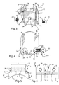
figure 4 is a partial and exploded assonometric view of a first construction particular of the pliers offigures 1-3 ; -
figure 5 is a first side view of a second construction particular of the pliers offigures 1-3 ; -
figure 6 is a second side view of the construction particular offigure 5 . - The modular pliers of the invention are shown in exploded and partial view in
figures 1-3 in which it is as a whole numbered with 1. - The
modular pliers 1 are mostly suitable for arranging a technical furniture, protection and/or delimitation structure, for simplicity not shown in the accompanying drawings and consisting of for example a stair banister or a partition wall of a room, including bearing structural elements, or uprights or columns, having a regular profile. - It is observed that the
modular pliers 1 comprise: - a
rear block 2 suitable to be firmly coupled with the side wall of the structural element of the technical structure; - a pair of
shaped jaws rear block 2 and opposite, facing and spaced apart each other in order to define aside seat 5 communicating with the outside and able to house a perimetrical portion of a slab, such as made of glass, clamped between theshaped jaws - In accordance with the invention, the
shaped jaws rear block 2 with which are firmly and removably coupled through first fastening means, overall indicated with 6. - The modular pliers also include properly second fastening means, only partially visible in the attached figures where they are overall indicated with 7, provided for the stable connection of
rear block 2 with the aforesaid bearing structural element. - In a preferred but not binding way, the
rear block 2 consists of: - a
base sector 8, which presents a firstlateral face 8a suitable to be conjugated to the side wall of the structural element of the technical structure; - a
spacing tooth 9, interposed between theshaped jaws lateral face 8b, opposite to thefirst face 8a, of thebase sector 8 so as to define with the latter a pair oflinear steps 10, 11 positioned laterally to thespacing tooth 9 symmetrically with respect to the main development axis Z of thespacing tooth 9 itself. - More precisely, the
spacing tooth 9 is made in single body with thebase sector 8 and presents afront surface 9a, facing theside seat 5, and twolateral surfaces - Even the
base sector 8 presents twoouter walls lower stretch 12 of theinner face shaped jaws outer walls - As
figure 5 also well illustrates, the firstlateral face 8a of thebase sector 8 presents, in this case, a concave profile in cross section, as themodular pliers 1 are properly suited to be coupled with uprights, usually with vertical axis, having a circular profile in cross section. - In other embodiments of the invention, not shown, the first lateral face of the base sector will present a linear profile, in cross section: the modular pliers of the invention will then be conveniently coupled with bearing structural elements, such as uprights or columns, having a square profile in cross section.
- In a preferred and advantageous way, the
spacing tooth 9 presents a quadrilateral, in this case rectangular, profile in cross section and a width L which is varied during production depending on the thickness of the slab housed in theside seat 5 and clamped between theshaped jaws - In particular, the width L of the
spacing tooth 9 is substantially equal to the thickness of the slab housed in theside seat 5. - Through the only variation of the width L of the
spacing tooth 9, the modular pliers of the invention adapts, therefore, to any thickness of the slab to be coupled with the bearing structural element, without intervening in any way on the constructive shape of theshaped jaws - Preferably but not necessarily, each of the
shaped jaws figure 4 . - In addition, the
shaped jaws inner faces outer faces - More specifically, each of the
shaped jaws longitudinal undercut 13, made in theinner face lower edge shaped jaws - The
longitudinal undercut 13 defines thelower stretch 12, placed close to the respectiveouter walls base sector 8, and atransverse wall 14 placed close to thesecond face 8b of thebase sector 8 along each of thelinear steps 10, 11. - The aforesaid
lower stretch 12 of theinner face shaped jaws outer walls base sector 8. - According to the preferred embodiment of the invention here described, the first fastening means 6 include, as
figures 1-4 highlights: - two first through nut screws 15, 16, made in the first shaped
jaw 3 at thelower stretch 12 according to a respective longitudinal axis X orthogonal to the plane Π defined by theinner face 3a of the shapedjaw 3; - two second through nut screws 17, 18, better seen in
figure 6 , made in thespacing tooth 9, each of which coaxial to one of the first nut screws 15, 16; - two third through nut screws 19, 20, made in a second shaped
jaw 4 at thelower section 12, each of which coaxial to one of the first nut screws 15, 16 and one of the second nut screws 17, 18; - two pairs of screws, only two of which visible in
figures 1-4 where they are indicated with 21, 22: afirst screw 21 engages thefirst nut screw 15 and partly in thesecond nut screw 18, while thesecond screw 22 engages thethird nut screw 19 and partly in thesecond nut screw 18 on the opposite side with respect to thefirst screw 21. - Preferably but not exclusively, each of the
screws annular groove 24 made around theinlet 25 of the first nut screws 15, 16 and third nut screws 19, 20 in such a way as that theouter wall 23a of the flat countersunkhead 23 is coplanar to theouter face jaws - It is understood that in other embodiments of the invention, not shown, the first fastening means may include a number of first through nut screws and, therefore, of second and third nut screws, different from that one described above, with this number that could vary at will starting from one.
- As far as the second fastening means 7 introduced before are concerned, they include:
- a through
opening 26, made in therear block 2 extending both thespacing tooth 9 and thebase sector 8 according to a linear axis Y orthogonal to the longitudinal axis X defined by thescrew nuts spacing tooth 9; - screw means, not shown in the attached figures for the sake of simplicity, contained in the through
opening 26 and suitable to engage at least partly the structural element of the technical structure. - At the
intermediate zone 27a, theinner wall 27 delimiting the throughopening 26 is preferably provided with anannular shoulder 28 which determines for the throughopening 26 itself a change in diameter starting from such anintermediate zone 27a. - The head of the screw means just cited is positioned close to the
annular shoulder 28, thus resulting totally and advantageously housed into the largest diameter portion of the throughopening 26. - In this way, the screw means are completely contained and, therefore, hidden in the
rear block 2, leading to the dual advantage of not interfering with the slab when house in theside seat 5 and positioned close to thefront surface 9a of thespacing tooth 9 and not affect in any way the aesthetic effect of the technical structure as a whole. - At preferential but not binding title, the
modular pliers 1 comprise stiffening means, applied to theinner face jaws tooth 9 of therear block 2 and the shapedjaws - The stiffening means include, mainly, a pair of
rubber gaskets main section 31 of theinner face jaws - Operatively, whereas the
modular pliers 1 are intended to be applied to a bearing structural element, usually a vertical upright, positioned at the end of a technical furniture, protection and/or delimitation structure, the operations performed essentially occur according to the following modes. - Firstly, the operator places the
rear block 2 close to the side wall of such a bearing structural element, in the chosen and correct position for the final configuration of the entire technical structure in question. - In a second time, by the second fastening means 7, the operator fixes the
rear block 2 to the bearing structural element of the technical structure that is under construction. - Once the
rubber gaskets main section 31 of theinner face jaws spacing tooth 9 of therear block 2, combining thelower section 12 to theouter wall 8c of thesame base sector 8 and placing thetransverse wall 14 close to the secondlateral face 8b of thebase sector 8. - Subsequently, the operator firmly couples the shaped
jaw 3 to therear block 2 by engaging thescrews 21 with the first through nut screws 15, 16 and partially with the second through nut screws 17, 18. - Then, the operator supports the edge of the slab onto the
front surface 9a of thespacing tooth 9 and finally firmly coupled with therear block 2 even the other shapedjaw 4, as done for the shapedjaw 3. - This means that the operator conjugates the
lower section 12 to theouter wall 8d of thebase sector 8, positioning thetransverse wall 14 close to the secondlateral face 8b of thebase sector 8, and engages thescrews 22 with the third through nut screws 19, 20 and partially with the second through nut screws 17, 18, on the opposite side with respect to the first screws 21. - The slab of the technical structure is thus contained in the
side seat 5, clamped between theshaped jaws modular pliers 1 just placed in their final operative configuration. - If an operator wishes or is forced to replace the slab just assembled with another one of different thicknesses, it will simply sufficient that he initially releases the shaped
jaws rear block 2, by removing thescrews rear block 2 from the bearing structural element, by removing the screw means from the throughopening 26. - At that point, the operator replaces only the
rear block 2 with another one comprising aspacing tooth 9 having width L greater or lower than therear block 2 just used, such a width L depending on the new thickness of the new slab to be coupled with the structural element of the technical structure. - The shaped
jaws modular pliers 1 previously used, since the length of thespacing tooth 9 of therear block 2, calculated according to the main development axis Z, does not vary in the different pliers designed according to the invention. - On the basis of the foregoing, it is, therefore, understood that the modular pliers for arranging technical furniture, protection and/or delimitation structures of the invention achieve the purposes and reach the advantages mentioned above.
- In execution phase, changes could be made to the modular pliers of the invention consisting of, for example, shaped jaws coupled with the rear block in such a way as to define more than one side seat suitable to house the perimetrical portion of a slab or panel belonging to the technical structure.
- In such a case, the modular pliers of the invention will be properly fixed to a bearing structural element (upright or column) placed in inner zones of the technical structure.
- In addition, further embodiments of the modular pliers here claimed could subsist wherein the first fastening means used to firmly connect the shaped jaws with the rear block are different from those ones previously described, which does not affect the advantage brought by the present invention.
- It is clear that many other variations may be made to the modular pliers in question, without departing from the principle of novelty intrinsic in the inventive idea expressed here, as it is clear that, in the practical implementation of the invention, materials, shapes and sizes of the illustrated details can be changed, as needed, and replaced with others technically equivalent.
- Where the constructive features and techniques mentioned in the following claims are followed by reference numbers or signs, those reference signs have been introduced with the sole objective of increasing the intelligibility of the claims themselves and therefore they have no limiting effect on the interpretation of each element identified, by way of example only, by these reference signs.
Claims (14)
- Modular pliers (1) for arranging technical furniture, protection and/or delimitation structures comprising:- a rear block (2) suitable to be firmly coupled with the side wall of a bearing structural element of said technical structure;- a pair of shaped jaws (3, 4) associated with said rear block (2) and placed opposite, facing and spaced apart each other in order to define at least one side seat (5) communicating with the outside and suitable to house a perimetrical portion of a slab clamped between said shaped jaws (3, 4) and belonging to said technical structure,characterized in that said shaped jaws (3, 4) are two pieces distinct and separated each other and from said rear block (2) with which are firmly and removably coupled through first fastening means (6).
- Pliers (1) as claim 1) characterized in that it include second fastening means (7) suitable to firmly connect said rear block (2) with said structural element.
- Pliers (1) as claim 1) or 2) characterized in that said rear block (2) is composed of:- a base sector (8) presenting a first lateral face (8a) suitable to be conjugated to said side wall of said structural element of said technical structure;- a spacing tooth (9), interposed between said shaped jaws (3, 4) and protruding from the central area of a second lateral face (8b), opposite to said first face (8a), of said base sector (8) so as to define with said base sector (8) a pair of linear steps (10, 11) positioned laterally to said spacing tooth (9) symmetrically with respect to the main development axis (Z) of said spacing tooth (9).
- Pliers (1) as claim 3) characterized in that said spacing tooth (9) is monolithic with said base sector (8) and presents a front surface (9a) facing said side seat (5) and two lateral surfaces (9b, 9c) defining planes equal and parallel each other.
- Pliers (1) as claim 3) or 4) characterized in that said base sector (8) presents two outer walls (8c, 8d) defining planes equal and parallel each other and close to which a lower stretch (12) of the inner face (3a, 4a) of said shaped jaws (3, 4) is positioned.
- Pliers as claim 3), 4) or 5) characterized in that said first lateral face of said base sector presents a linear profile in cross section.
- Pliers (1) as claim 3), 4) or 5) characterized in that said first lateral face (8a) of said base sector (8) presents a concave profile in cross section.
- Pliers (1) as any one of the claims from 3) to 7) characterized in that said spacing tooth (9) presents in cross section a quadrilateral profile and a width (L) suitable to be varied in production phase depending on the thickness of said slab housed in said side seat (5) and clamped between said shaped jaws (3, 4).
- Pliers (1) as any one of the claims from 4) to 8) characterized in that each of said shaped jaws (3, 4) presents a longitudinal undercut (13), made in said inner face (3a, 4a) starting from the lower edge (3c, 4c) to the central area of each of said shaped jaws (3, 4) and defining said lower stretch (12), placed close to one of said outer walls (8c, 8d) of said base sector (8), and a transverse wall (14) arranged close to said second face (8b) of said base sector (8) along each of said linear steps (10, 11).
- Pliers (1) as claim 9) characterized in that said lower stretch (12) of said inner face (3a, 4a) of each of said shaped jaws (3, 4) presents substantially the same height (H) of each of said outer walls (8c, 8d) of said base sector (8).
- Pliers (1) as any one of the claims from 4) to 10) characterized in that said first fastening means (6) include:- at least one first through nut screw (15, 16) made in a first of said shaped jaws (3, 4) at said lower stretch (12) according to a longitudinal axis (X) orthogonal to the plane (n) defined by said inner face (3a, 4a) of each of said shaped jaws (3, 4);- at least a second through nut screw (17, 18) made in said spacing tooth (9) and coaxial to said first nut screw (15, 16);- at least a third through nut screw (19, 20) made in the other of said shaped jaws (3, 4) at said lower stretch (12) and coaxial to said first (15, 16) and second nut screw (17, 18);- at least a couple of screws (21, 22), a first screw (21) engaging into said first nut screw (15, 16) and partially into said second nut screw (17, 18) and a second screw (22) engaging into said third nut screw (19, 20) and partially into said second nut screw (17, 18) on the opposite side with respect to said first screw (21).
- Pliers (1) as claim 11) characterized in that each of said screws (21, 22) is of the flat countersunk head (23) type which is housed in an annular groove (24) made around the inlet (25) of said first (15, 16) and third nut screws (19, 20) so that the outer wall (23a) of said flat countersunk head (23) is coplanar to the outer face (3b, 4b) of said shaped jaws (3, 4).
- Pliers (1) as claim 11) or 12) characterized in that said second fastening means (7) include:- a through opening (26), made in said rear block (2) extending along said spacing tooth (9) and said base sector (8) according to a linear axis (Y) orthogonal to said longitudinal axis (X) defined by said nut screws (15, 16, 17, 18, 19, 20);- screw means contained into said through opening (26) and suitable to engage into said structural element of said technical structure.
- Pliers (1) as claim 13) characterized in that, at the intermediate zone (27a), the inner wall (27) delimiting said through opening (26) is provided with an annular shoulder (28) which determines for said through opening (26) a change in diameter starting from said intermediate zone (27a) and against which the head of said screw means, completely housed into the largest diameter portion of said through opening (26), is arranged close.
Applications Claiming Priority (1)
| Application Number | Priority Date | Filing Date | Title |
|---|---|---|---|
| ITVI2010A000019A IT1398452B1 (en) | 2010-02-02 | 2010-02-02 | CALIPER FOR THE COMPOSITION OF TECHNICAL FURNITURE, PROTECTION AND / OR DELIMITATION STRUCTURES |
Publications (2)
| Publication Number | Publication Date |
|---|---|
| EP2354565A1 true EP2354565A1 (en) | 2011-08-10 |
| EP2354565B1 EP2354565B1 (en) | 2013-02-20 |
Family
ID=42357497
Family Applications (1)
| Application Number | Title | Priority Date | Filing Date |
|---|---|---|---|
| EP20100425356 Not-in-force EP2354565B1 (en) | 2010-02-02 | 2010-11-19 | Modular pliers for arranging technical furniture, protection and/or delimitation structures |
Country Status (2)
| Country | Link |
|---|---|
| EP (1) | EP2354565B1 (en) |
| IT (1) | IT1398452B1 (en) |
Cited By (1)
| Publication number | Priority date | Publication date | Assignee | Title |
|---|---|---|---|---|
| DE102012200110A1 (en) * | 2012-01-05 | 2013-07-11 | Bilfinger Berger Ingenieurbau Gmbh | Device for fastening objects to a wall |
Citations (4)
| Publication number | Priority date | Publication date | Assignee | Title |
|---|---|---|---|---|
| BE388449A (en) * | ||||
| DE8604984U1 (en) * | 1986-02-25 | 1986-04-10 | Ihr Messerepraesentant Dipl.-Wirtsch.Ing. Peter J. Bodensohn, 6128 Hoechst | Wall element for temporary erectable and demountable lightweight structures |
| DE3727486A1 (en) * | 1986-08-21 | 1988-02-25 | Jorge Antones Grau | Device for dividing up rooms |
| EP1764517A2 (en) * | 2005-09-19 | 2007-03-21 | Wanzl Metallwarenfabrik GmbH | Partition |
-
2010
- 2010-02-02 IT ITVI2010A000019A patent/IT1398452B1/en active
- 2010-11-19 EP EP20100425356 patent/EP2354565B1/en not_active Not-in-force
Patent Citations (4)
| Publication number | Priority date | Publication date | Assignee | Title |
|---|---|---|---|---|
| BE388449A (en) * | ||||
| DE8604984U1 (en) * | 1986-02-25 | 1986-04-10 | Ihr Messerepraesentant Dipl.-Wirtsch.Ing. Peter J. Bodensohn, 6128 Hoechst | Wall element for temporary erectable and demountable lightweight structures |
| DE3727486A1 (en) * | 1986-08-21 | 1988-02-25 | Jorge Antones Grau | Device for dividing up rooms |
| EP1764517A2 (en) * | 2005-09-19 | 2007-03-21 | Wanzl Metallwarenfabrik GmbH | Partition |
Cited By (1)
| Publication number | Priority date | Publication date | Assignee | Title |
|---|---|---|---|---|
| DE102012200110A1 (en) * | 2012-01-05 | 2013-07-11 | Bilfinger Berger Ingenieurbau Gmbh | Device for fastening objects to a wall |
Also Published As
| Publication number | Publication date |
|---|---|
| IT1398452B1 (en) | 2013-02-22 |
| EP2354565B1 (en) | 2013-02-20 |
| ITVI20100019A1 (en) | 2011-08-03 |
Similar Documents
| Publication | Publication Date | Title |
|---|---|---|
| US9382715B2 (en) | Building array | |
| EP2852720B1 (en) | Construction set and fixing system for ventilated claddings | |
| US11067218B2 (en) | Mounting system for attaching accessory items to a wall | |
| JP2003204827A (en) | Desk system | |
| EP2354565B1 (en) | Modular pliers for arranging technical furniture, protection and/or delimitation structures | |
| KR102290321B1 (en) | Adjustable self with decoration cover | |
| EP3005904B1 (en) | Supporting structure with supporting profile and support arms | |
| US20130111827A1 (en) | Tool-less modular panel system | |
| KR20210000299U (en) | Display shelf bracket for Display rack | |
| US20070062127A1 (en) | System for fastening articles, such as shelves and work tops, to the uprights of a structure | |
| EP3753457A1 (en) | Decorative and / or construction frame | |
| RU2761225C2 (en) | Separating element for boiserie | |
| EP2990558B1 (en) | Wall building system and method for builing said wall system | |
| CN109914728B (en) | Hanging structure of wallboard and laminate | |
| US6105327A (en) | Panel structure | |
| US20070095000A1 (en) | Modular moulding with fitted spline joinery system | |
| EP2709488B1 (en) | Piece of furniture composed of panels that can be assembled by means of connecting strips | |
| RU151840U1 (en) | DOOR | |
| IT201900018923A1 (en) | A load-bearing metal structure covered in a predetermined material, in order to form a module that is part of a kitchen furniture | |
| EP2281969B1 (en) | Modular clamp for panels | |
| KR20130104946A (en) | Handrail bracket and jig for assembling the handrail | |
| CN211323661U (en) | Cabinet body structure | |
| RU2005124882A (en) | FURNITURE SHIELD CONNECTIONS ASSEMBLY | |
| JP3227864U (en) | Assembled shelves | |
| EP2021553B1 (en) | Post assembly for partitioning walls |
Legal Events
| Date | Code | Title | Description |
|---|---|---|---|
| PUAI | Public reference made under article 153(3) epc to a published international application that has entered the european phase |
Free format text: ORIGINAL CODE: 0009012 |
|
| AK | Designated contracting states |
Kind code of ref document: A1 Designated state(s): AL AT BE BG CH CY CZ DE DK EE ES FI FR GB GR HR HU IE IS IT LI LT LU LV MC MK MT NL NO PL PT RO RS SE SI SK SM TR |
|
| AX | Request for extension of the european patent |
Extension state: BA ME |
|
| 17P | Request for examination filed |
Effective date: 20120109 |
|
| GRAP | Despatch of communication of intention to grant a patent |
Free format text: ORIGINAL CODE: EPIDOSNIGR1 |
|
| GRAS | Grant fee paid |
Free format text: ORIGINAL CODE: EPIDOSNIGR3 |
|
| GRAA | (expected) grant |
Free format text: ORIGINAL CODE: 0009210 |
|
| AK | Designated contracting states |
Kind code of ref document: B1 Designated state(s): AL AT BE BG CH CY CZ DE DK EE ES FI FR GB GR HR HU IE IS IT LI LT LU LV MC MK MT NL NO PL PT RO RS SE SI SK SM TR |
|
| REG | Reference to a national code |
Ref country code: GB Ref legal event code: FG4D |
|
| REG | Reference to a national code |
Ref country code: CH Ref legal event code: EP |
|
| REG | Reference to a national code |
Ref country code: AT Ref legal event code: REF Ref document number: 597684 Country of ref document: AT Kind code of ref document: T Effective date: 20130315 |
|
| REG | Reference to a national code |
Ref country code: IE Ref legal event code: FG4D |
|
| REG | Reference to a national code |
Ref country code: DE Ref legal event code: R096 Ref document number: 602010005115 Country of ref document: DE Effective date: 20130418 |
|
| REG | Reference to a national code |
Ref country code: AT Ref legal event code: MK05 Ref document number: 597684 Country of ref document: AT Kind code of ref document: T Effective date: 20130220 |
|
| REG | Reference to a national code |
Ref country code: NL Ref legal event code: VDEP Effective date: 20130220 |
|
| REG | Reference to a national code |
Ref country code: LT Ref legal event code: MG4D |
|
| PG25 | Lapsed in a contracting state [announced via postgrant information from national office to epo] |
Ref country code: NO Free format text: LAPSE BECAUSE OF FAILURE TO SUBMIT A TRANSLATION OF THE DESCRIPTION OR TO PAY THE FEE WITHIN THE PRESCRIBED TIME-LIMIT Effective date: 20130520 Ref country code: LT Free format text: LAPSE BECAUSE OF FAILURE TO SUBMIT A TRANSLATION OF THE DESCRIPTION OR TO PAY THE FEE WITHIN THE PRESCRIBED TIME-LIMIT Effective date: 20130220 Ref country code: IS Free format text: LAPSE BECAUSE OF FAILURE TO SUBMIT A TRANSLATION OF THE DESCRIPTION OR TO PAY THE FEE WITHIN THE PRESCRIBED TIME-LIMIT Effective date: 20130620 Ref country code: SE Free format text: LAPSE BECAUSE OF FAILURE TO SUBMIT A TRANSLATION OF THE DESCRIPTION OR TO PAY THE FEE WITHIN THE PRESCRIBED TIME-LIMIT Effective date: 20130220 Ref country code: AT Free format text: LAPSE BECAUSE OF FAILURE TO SUBMIT A TRANSLATION OF THE DESCRIPTION OR TO PAY THE FEE WITHIN THE PRESCRIBED TIME-LIMIT Effective date: 20130220 Ref country code: BG Free format text: LAPSE BECAUSE OF FAILURE TO SUBMIT A TRANSLATION OF THE DESCRIPTION OR TO PAY THE FEE WITHIN THE PRESCRIBED TIME-LIMIT Effective date: 20130520 Ref country code: ES Free format text: LAPSE BECAUSE OF FAILURE TO SUBMIT A TRANSLATION OF THE DESCRIPTION OR TO PAY THE FEE WITHIN THE PRESCRIBED TIME-LIMIT Effective date: 20130531 |
|
| PG25 | Lapsed in a contracting state [announced via postgrant information from national office to epo] |
Ref country code: LV Free format text: LAPSE BECAUSE OF FAILURE TO SUBMIT A TRANSLATION OF THE DESCRIPTION OR TO PAY THE FEE WITHIN THE PRESCRIBED TIME-LIMIT Effective date: 20130220 Ref country code: PL Free format text: LAPSE BECAUSE OF FAILURE TO SUBMIT A TRANSLATION OF THE DESCRIPTION OR TO PAY THE FEE WITHIN THE PRESCRIBED TIME-LIMIT Effective date: 20130220 Ref country code: FI Free format text: LAPSE BECAUSE OF FAILURE TO SUBMIT A TRANSLATION OF THE DESCRIPTION OR TO PAY THE FEE WITHIN THE PRESCRIBED TIME-LIMIT Effective date: 20130220 Ref country code: BE Free format text: LAPSE BECAUSE OF FAILURE TO SUBMIT A TRANSLATION OF THE DESCRIPTION OR TO PAY THE FEE WITHIN THE PRESCRIBED TIME-LIMIT Effective date: 20130220 Ref country code: PT Free format text: LAPSE BECAUSE OF FAILURE TO SUBMIT A TRANSLATION OF THE DESCRIPTION OR TO PAY THE FEE WITHIN THE PRESCRIBED TIME-LIMIT Effective date: 20130620 Ref country code: SI Free format text: LAPSE BECAUSE OF FAILURE TO SUBMIT A TRANSLATION OF THE DESCRIPTION OR TO PAY THE FEE WITHIN THE PRESCRIBED TIME-LIMIT Effective date: 20130220 Ref country code: GR Free format text: LAPSE BECAUSE OF FAILURE TO SUBMIT A TRANSLATION OF THE DESCRIPTION OR TO PAY THE FEE WITHIN THE PRESCRIBED TIME-LIMIT Effective date: 20130521 |
|
| PG25 | Lapsed in a contracting state [announced via postgrant information from national office to epo] |
Ref country code: RS Free format text: LAPSE BECAUSE OF FAILURE TO SUBMIT A TRANSLATION OF THE DESCRIPTION OR TO PAY THE FEE WITHIN THE PRESCRIBED TIME-LIMIT Effective date: 20130220 Ref country code: HR Free format text: LAPSE BECAUSE OF FAILURE TO SUBMIT A TRANSLATION OF THE DESCRIPTION OR TO PAY THE FEE WITHIN THE PRESCRIBED TIME-LIMIT Effective date: 20130220 |
|
| PG25 | Lapsed in a contracting state [announced via postgrant information from national office to epo] |
Ref country code: EE Free format text: LAPSE BECAUSE OF FAILURE TO SUBMIT A TRANSLATION OF THE DESCRIPTION OR TO PAY THE FEE WITHIN THE PRESCRIBED TIME-LIMIT Effective date: 20130220 Ref country code: DK Free format text: LAPSE BECAUSE OF FAILURE TO SUBMIT A TRANSLATION OF THE DESCRIPTION OR TO PAY THE FEE WITHIN THE PRESCRIBED TIME-LIMIT Effective date: 20130220 Ref country code: NL Free format text: LAPSE BECAUSE OF FAILURE TO SUBMIT A TRANSLATION OF THE DESCRIPTION OR TO PAY THE FEE WITHIN THE PRESCRIBED TIME-LIMIT Effective date: 20130220 Ref country code: RO Free format text: LAPSE BECAUSE OF FAILURE TO SUBMIT A TRANSLATION OF THE DESCRIPTION OR TO PAY THE FEE WITHIN THE PRESCRIBED TIME-LIMIT Effective date: 20130220 Ref country code: CZ Free format text: LAPSE BECAUSE OF FAILURE TO SUBMIT A TRANSLATION OF THE DESCRIPTION OR TO PAY THE FEE WITHIN THE PRESCRIBED TIME-LIMIT Effective date: 20130220 Ref country code: SK Free format text: LAPSE BECAUSE OF FAILURE TO SUBMIT A TRANSLATION OF THE DESCRIPTION OR TO PAY THE FEE WITHIN THE PRESCRIBED TIME-LIMIT Effective date: 20130220 |
|
| PLBE | No opposition filed within time limit |
Free format text: ORIGINAL CODE: 0009261 |
|
| STAA | Information on the status of an ep patent application or granted ep patent |
Free format text: STATUS: NO OPPOSITION FILED WITHIN TIME LIMIT |
|
| PG25 | Lapsed in a contracting state [announced via postgrant information from national office to epo] |
Ref country code: IT Free format text: LAPSE BECAUSE OF FAILURE TO SUBMIT A TRANSLATION OF THE DESCRIPTION OR TO PAY THE FEE WITHIN THE PRESCRIBED TIME-LIMIT Effective date: 20130220 |
|
| 26N | No opposition filed |
Effective date: 20131121 |
|
| REG | Reference to a national code |
Ref country code: DE Ref legal event code: R097 Ref document number: 602010005115 Country of ref document: DE Effective date: 20131121 |
|
| PG25 | Lapsed in a contracting state [announced via postgrant information from national office to epo] |
Ref country code: MC Free format text: LAPSE BECAUSE OF FAILURE TO SUBMIT A TRANSLATION OF THE DESCRIPTION OR TO PAY THE FEE WITHIN THE PRESCRIBED TIME-LIMIT Effective date: 20130220 |
|
| REG | Reference to a national code |
Ref country code: IE Ref legal event code: MM4A |
|
| PG25 | Lapsed in a contracting state [announced via postgrant information from national office to epo] |
Ref country code: IE Free format text: LAPSE BECAUSE OF NON-PAYMENT OF DUE FEES Effective date: 20131119 |
|
| PG25 | Lapsed in a contracting state [announced via postgrant information from national office to epo] |
Ref country code: SM Free format text: LAPSE BECAUSE OF FAILURE TO SUBMIT A TRANSLATION OF THE DESCRIPTION OR TO PAY THE FEE WITHIN THE PRESCRIBED TIME-LIMIT Effective date: 20130220 |
|
| PG25 | Lapsed in a contracting state [announced via postgrant information from national office to epo] |
Ref country code: CY Free format text: LAPSE BECAUSE OF FAILURE TO SUBMIT A TRANSLATION OF THE DESCRIPTION OR TO PAY THE FEE WITHIN THE PRESCRIBED TIME-LIMIT Effective date: 20130220 Ref country code: TR Free format text: LAPSE BECAUSE OF FAILURE TO SUBMIT A TRANSLATION OF THE DESCRIPTION OR TO PAY THE FEE WITHIN THE PRESCRIBED TIME-LIMIT Effective date: 20130220 |
|
| REG | Reference to a national code |
Ref country code: CH Ref legal event code: PL |
|
| GBPC | Gb: european patent ceased through non-payment of renewal fee |
Effective date: 20141119 |
|
| PG25 | Lapsed in a contracting state [announced via postgrant information from national office to epo] |
Ref country code: MK Free format text: LAPSE BECAUSE OF FAILURE TO SUBMIT A TRANSLATION OF THE DESCRIPTION OR TO PAY THE FEE WITHIN THE PRESCRIBED TIME-LIMIT Effective date: 20130220 Ref country code: LU Free format text: LAPSE BECAUSE OF NON-PAYMENT OF DUE FEES Effective date: 20131119 Ref country code: LI Free format text: LAPSE BECAUSE OF NON-PAYMENT OF DUE FEES Effective date: 20141130 Ref country code: HU Free format text: LAPSE BECAUSE OF FAILURE TO SUBMIT A TRANSLATION OF THE DESCRIPTION OR TO PAY THE FEE WITHIN THE PRESCRIBED TIME-LIMIT; INVALID AB INITIO Effective date: 20101119 Ref country code: CH Free format text: LAPSE BECAUSE OF NON-PAYMENT OF DUE FEES Effective date: 20141130 |
|
| PG25 | Lapsed in a contracting state [announced via postgrant information from national office to epo] |
Ref country code: MT Free format text: LAPSE BECAUSE OF FAILURE TO SUBMIT A TRANSLATION OF THE DESCRIPTION OR TO PAY THE FEE WITHIN THE PRESCRIBED TIME-LIMIT Effective date: 20130220 |
|
| REG | Reference to a national code |
Ref country code: FR Ref legal event code: PLFP Year of fee payment: 6 |
|
| PG25 | Lapsed in a contracting state [announced via postgrant information from national office to epo] |
Ref country code: GB Free format text: LAPSE BECAUSE OF NON-PAYMENT OF DUE FEES Effective date: 20141119 |
|
| REG | Reference to a national code |
Ref country code: FR Ref legal event code: PLFP Year of fee payment: 7 |
|
| REG | Reference to a national code |
Ref country code: FR Ref legal event code: PLFP Year of fee payment: 8 |
|
| PGFP | Annual fee paid to national office [announced via postgrant information from national office to epo] |
Ref country code: FR Payment date: 20171012 Year of fee payment: 8 Ref country code: DE Payment date: 20171124 Year of fee payment: 8 |
|
| PG25 | Lapsed in a contracting state [announced via postgrant information from national office to epo] |
Ref country code: AL Free format text: LAPSE BECAUSE OF FAILURE TO SUBMIT A TRANSLATION OF THE DESCRIPTION OR TO PAY THE FEE WITHIN THE PRESCRIBED TIME-LIMIT Effective date: 20130220 |
|
| REG | Reference to a national code |
Ref country code: DE Ref legal event code: R119 Ref document number: 602010005115 Country of ref document: DE |
|
| PG25 | Lapsed in a contracting state [announced via postgrant information from national office to epo] |
Ref country code: FR Free format text: LAPSE BECAUSE OF NON-PAYMENT OF DUE FEES Effective date: 20181130 Ref country code: DE Free format text: LAPSE BECAUSE OF NON-PAYMENT OF DUE FEES Effective date: 20190601 |