EP2354316A1 - Piste maintenance vehicle - Google Patents
Piste maintenance vehicle Download PDFInfo
- Publication number
- EP2354316A1 EP2354316A1 EP11153413A EP11153413A EP2354316A1 EP 2354316 A1 EP2354316 A1 EP 2354316A1 EP 11153413 A EP11153413 A EP 11153413A EP 11153413 A EP11153413 A EP 11153413A EP 2354316 A1 EP2354316 A1 EP 2354316A1
- Authority
- EP
- European Patent Office
- Prior art keywords
- sensor device
- vehicle
- piste
- detected
- piste grooming
- Prior art date
- Legal status (The legal status is an assumption and is not a legal conclusion. Google has not performed a legal analysis and makes no representation as to the accuracy of the status listed.)
- Granted
Links
Images

Classifications
-
- E—FIXED CONSTRUCTIONS
- E01—CONSTRUCTION OF ROADS, RAILWAYS, OR BRIDGES
- E01H—STREET CLEANING; CLEANING OF PERMANENT WAYS; CLEANING BEACHES; DISPERSING OR PREVENTING FOG IN GENERAL CLEANING STREET OR RAILWAY FURNITURE OR TUNNEL WALLS
- E01H4/00—Working on surfaces of snow or ice in order to make them suitable for traffic or sporting purposes, e.g. by compacting snow
- E01H4/02—Working on surfaces of snow or ice in order to make them suitable for traffic or sporting purposes, e.g. by compacting snow for sporting purposes, e.g. preparation of ski trails; Construction of artificial surfacings for snow or ice sports ; Trails specially adapted for on-the-snow vehicles, e.g. devices adapted for ski-trails
-
- F—MECHANICAL ENGINEERING; LIGHTING; HEATING; WEAPONS; BLASTING
- F16—ENGINEERING ELEMENTS AND UNITS; GENERAL MEASURES FOR PRODUCING AND MAINTAINING EFFECTIVE FUNCTIONING OF MACHINES OR INSTALLATIONS; THERMAL INSULATION IN GENERAL
- F16P—SAFETY DEVICES IN GENERAL; SAFETY DEVICES FOR PRESSES
- F16P3/00—Safety devices acting in conjunction with the control or operation of a machine; Control arrangements requiring the simultaneous use of two or more parts of the body
- F16P3/12—Safety devices acting in conjunction with the control or operation of a machine; Control arrangements requiring the simultaneous use of two or more parts of the body with means, e.g. feelers, which in case of the presence of a body part of a person in or near the danger zone influence the control or operation of the machine
- F16P3/14—Safety devices acting in conjunction with the control or operation of a machine; Control arrangements requiring the simultaneous use of two or more parts of the body with means, e.g. feelers, which in case of the presence of a body part of a person in or near the danger zone influence the control or operation of the machine the means being photocells or other devices sensitive without mechanical contact
- F16P3/142—Safety devices acting in conjunction with the control or operation of a machine; Control arrangements requiring the simultaneous use of two or more parts of the body with means, e.g. feelers, which in case of the presence of a body part of a person in or near the danger zone influence the control or operation of the machine the means being photocells or other devices sensitive without mechanical contact using image capturing devices
-
- F—MECHANICAL ENGINEERING; LIGHTING; HEATING; WEAPONS; BLASTING
- F16—ENGINEERING ELEMENTS AND UNITS; GENERAL MEASURES FOR PRODUCING AND MAINTAINING EFFECTIVE FUNCTIONING OF MACHINES OR INSTALLATIONS; THERMAL INSULATION IN GENERAL
- F16P—SAFETY DEVICES IN GENERAL; SAFETY DEVICES FOR PRESSES
- F16P3/00—Safety devices acting in conjunction with the control or operation of a machine; Control arrangements requiring the simultaneous use of two or more parts of the body
- F16P3/12—Safety devices acting in conjunction with the control or operation of a machine; Control arrangements requiring the simultaneous use of two or more parts of the body with means, e.g. feelers, which in case of the presence of a body part of a person in or near the danger zone influence the control or operation of the machine
- F16P3/14—Safety devices acting in conjunction with the control or operation of a machine; Control arrangements requiring the simultaneous use of two or more parts of the body with means, e.g. feelers, which in case of the presence of a body part of a person in or near the danger zone influence the control or operation of the machine the means being photocells or other devices sensitive without mechanical contact
- F16P3/144—Safety devices acting in conjunction with the control or operation of a machine; Control arrangements requiring the simultaneous use of two or more parts of the body with means, e.g. feelers, which in case of the presence of a body part of a person in or near the danger zone influence the control or operation of the machine the means being photocells or other devices sensitive without mechanical contact using light grids
-
- F—MECHANICAL ENGINEERING; LIGHTING; HEATING; WEAPONS; BLASTING
- F16—ENGINEERING ELEMENTS AND UNITS; GENERAL MEASURES FOR PRODUCING AND MAINTAINING EFFECTIVE FUNCTIONING OF MACHINES OR INSTALLATIONS; THERMAL INSULATION IN GENERAL
- F16P—SAFETY DEVICES IN GENERAL; SAFETY DEVICES FOR PRESSES
- F16P3/00—Safety devices acting in conjunction with the control or operation of a machine; Control arrangements requiring the simultaneous use of two or more parts of the body
- F16P3/12—Safety devices acting in conjunction with the control or operation of a machine; Control arrangements requiring the simultaneous use of two or more parts of the body with means, e.g. feelers, which in case of the presence of a body part of a person in or near the danger zone influence the control or operation of the machine
- F16P3/14—Safety devices acting in conjunction with the control or operation of a machine; Control arrangements requiring the simultaneous use of two or more parts of the body with means, e.g. feelers, which in case of the presence of a body part of a person in or near the danger zone influence the control or operation of the machine the means being photocells or other devices sensitive without mechanical contact
- F16P3/147—Safety devices acting in conjunction with the control or operation of a machine; Control arrangements requiring the simultaneous use of two or more parts of the body with means, e.g. feelers, which in case of the presence of a body part of a person in or near the danger zone influence the control or operation of the machine the means being photocells or other devices sensitive without mechanical contact using electro-magnetic technology, e.g. tags or radar
-
- F—MECHANICAL ENGINEERING; LIGHTING; HEATING; WEAPONS; BLASTING
- F16—ENGINEERING ELEMENTS AND UNITS; GENERAL MEASURES FOR PRODUCING AND MAINTAINING EFFECTIVE FUNCTIONING OF MACHINES OR INSTALLATIONS; THERMAL INSULATION IN GENERAL
- F16P—SAFETY DEVICES IN GENERAL; SAFETY DEVICES FOR PRESSES
- F16P3/00—Safety devices acting in conjunction with the control or operation of a machine; Control arrangements requiring the simultaneous use of two or more parts of the body
- F16P3/12—Safety devices acting in conjunction with the control or operation of a machine; Control arrangements requiring the simultaneous use of two or more parts of the body with means, e.g. feelers, which in case of the presence of a body part of a person in or near the danger zone influence the control or operation of the machine
- F16P3/16—Safety devices acting in conjunction with the control or operation of a machine; Control arrangements requiring the simultaneous use of two or more parts of the body with means, e.g. feelers, which in case of the presence of a body part of a person in or near the danger zone influence the control or operation of the machine with feeling members moved by the machine
Definitions
- the invention relates to a piste grooming vehicle with a chain drive and / or at least one cultivation unit for processing a substrate.
- Such piste maintenance vehicles usually have a chain drive with two chains, which are particularly well suited to ski trails for locomotion of the vehicle.
- Such piste maintenance vehicles often also have cultivation units such as in particular snow blowers, which are mounted in particular at the rear of the vehicle and are used to process the snow surface.
- cultivation units are also known from other fields, for example of generic beach care vehicles, in which the cultivation units serve to receive sand to eliminate impurities from this.
- the object of the invention is to develop a generic piste care vehicle to the effect that the risk of serious injury in connection with the chain drive and / or the power packs is reduced and / or that the risk to the driver and the vehicle is reduced, resulting from dangerous ground contours like columns and slopes.
- a generic piste grooming vehicle has a safety system which has a sensor device for detecting persons and / or ground contours in the surroundings of the vehicle and which is designed to secure the chain drive and / or the cultivating unit upon detection of a person endangered thereby deactivate.
- the security system is designed to emit an optical or audible warning signal if a person at risk of the vehicle is detected, wherein the warning signal is designed such that it can be detected by the person at risk.
- the vehicle may be configured to display the detected ground contours and / or the detected persons visualized on a screen in the cab of the vehicle.
- a piste grooming vehicle is thus enabled by the sensor device to automatically deactivate the chain drive and / or the attachment in order to avoid the injury of persons who might come into contact with the chain drive or the attachment.
- the commonality of the Kettenfahrantriebs and the growing unit, the externally accessible moving parts at low altitude above the ground, are mitigated in terms of their risk that they are brought to a standstill in a dangerous situation threatens.
- the security system designed in this way is therefore not primarily designed to avoid an impending contact, since this is generally not possible anyway due to the low speed of the piste grooming vehicle and the comparatively high speeds of the persons, in particular skiers. Instead, the risk of injury is significantly reduced by deactivating the chain drive or the attachments. Thus, a person, particularly a skier, who collides with the vehicle may suffer damage from the impact itself, despite the safety system, but will not suffer serious injury from pinching between the chain and sprockets or from contact with the rotating parts of a snowthrower and similar cropping aggregates.
- an endangered person in particular a skier
- the warning is for example via a horn, in particular with a volume of at least 80 decibels, preferably at least 100 decibels, or a clearly visible and strong warning lamp.
- the safety system preferably has several possible reaction variants such as the deactivation of the traction drive, the differentiated deactivation of one or more cultivating units and the delivery of a warning signal.
- the safety system is preferably designed to select the appropriate reaction variants as a function of the detected danger situation, wherein in particular also the current driving situation (direction of travel, inclination of the ground) of the vehicle can be included.
- the deactivation of the rear snow blower is required, while the traction drive can or should remain in operation, in order to reduce the relative impact speed.
- the security system is preferably designed to effect such a differentiated response.
- a vehicle according to the invention can achieve a significant reduction in risk for the driver and the vehicle by virtue of the visualized information transmission to the driver with regard to persons located in the surroundings or the ground contours in the surroundings of the vehicle.
- the driver can reliably recognize and respond to persons who are in the vicinity of the vehicle by the information displayed on a screen.
- by visualizing the contours of the ground he can grasp the dangers arising from slopes, cracks and the like and react appropriately. This is of great importance in generic snow grooming vehicles, because these are used in the alpine area, in which it can make very sudden changes in weather conditions, the vehicle even lead when the human eye is hardly able to contours in the environment of the vehicle.
- this snowblower may be a snow-blower, in particular at the rear, for producing a homogeneous substrate or a front-side snowblower for removing excess snow.
- an attachment which comprises a boom with respect to a main body of the boom driven movable processing elements for producing a half-pipe.
- a piste grooming vehicle is furthermore also expedient, since it is precisely a piste grooming vehicle which is exposed to particular hazards as a result of its use in the snow-covered mountains, which can be counteracted particularly well by an embodiment according to the invention having a sensor device for detecting ground contours.
- the chain drive and the attachment of the vehicle can be driven for example by an internal combustion engine or an electric motor. It is particularly advantageous, however, if the chain drive or the attachment is driven by a hydraulic motor.
- a hydraulic motor is integrated into a hydraulic circuit with a hydraulic pump and converts the energy supplied via the hydraulic fluid into mechanical energy, in particular into a rotational movement.
- the advantage of using such a hydraulic motor is the particular suitability for immediate braking. Once the supply of pressurized hydraulic fluid is prevented, come Chain drive or the attachment immediately to a standstill, without the need for separate braking devices.
- the sensor device For detecting persons and ground contours in the vicinity of the runway care vehicle, the sensor device preferably comprises an infrared sensor device, a laser sensor device and / or a radar device.
- the infrared sensor device is preferably a thermal imaging camera, which can also detect persons when they are not moving and, for example, are difficult to detect after a fall even for a laser sensor device or a radar device.
- the infrared sensor device can also be designed / aligned such that persons located in the immediate vicinity of the snow surface or even located below the snow surface are detected.
- the laser sensor device can also be designed as a 3D laser sensor device which detects the environment three-dimensionally.
- the aforementioned types of sensor devices each have advantages and disadvantages, preferably several of them are provided together on a piste grooming vehicle, wherein they may have different or even overlapping detection areas.
- the various types of sensor devices can be connected to a common evaluation unit, which on the basis of the various input data can draw a reliable picture of a possible hazard to persons for the purpose of further evaluation.
- the piste grooming vehicle has an infrared sensor device whose detection area is arranged exclusively in the longitudinal direction in front of and / or behind the piste grooming vehicle and has a blind spot next to the vehicle, and wherein the piste grooming vehicle further comprises a laser sensor device, in particular a 3D sensor. Laser sensor device, and / or a radar device whose detection range is arranged at least in the vehicle transverse direction next to the piste grooming vehicle.
- Such an arrangement makes it possible to direct the infrared sensor device only to detection areas, which are achieved by the vehicle during its driving movement to reliably in these areas, the injury of lying for example in the snow or other reasons by a radar device or a laser sensor device people detect.
- the laser sensor device or the radar device additionally detects the side areas of the vehicle, so that people moving there can be detected. Persons lying in the side areas, which would only be detectable for the infrared sensor device, are not of interest for the safety system since they are not endangered.
- the transmitter extrapolates their movement path to detect whether these people could come into contact with the piste grooming vehicle.
- the evaluation of the controller is designed to disable the chain drive or the attachment in a personal hazard.
- the security system is further adapted to be audiovisual Issue warning message to the driver, for example in the form of a warning tone or a display on the instrument panel or a screen of the vehicle.
- Such an audiovisual warning message preferably takes place even at a lower degree of danger to a person, so that an escalating danger situation initially only accompanies such an audiovisual warning message and the deactivation of the chain drive and / or the attachment occurs only in the course of the tapering.
- Such a design thus allows, for example, the driver of the piste grooming vehicle to respond automatically to the danger situation.
- the vehicle has a camera for optical detection of the environment, wherein the image captured by this camera is displayed on the screen in the cab and wherein the image displayed on the screen is supplemented by information detected by the sensor device.
- the information displayed can originate in particular from an infrared sensor device or a laser sensor device.
- Information of the infrared sensor device are preferably processed such that the thus detected heat sources are displayed at the appropriate location in the camera image, for example in the form of red dots or the like.
- the ground contours detected by this laser sensor device are superimposed in the image displayed on the screen.
- existing obstacles such as trees or rocks can be detected by the laser sensor device and displayed at the respective corresponding point in the image of the camera.
- the laser sensor device is used to visualize danger spots in the underground.
- gaps in the floor as well as slopes and breaks at the corresponding points in the camera image can be displayed.
- this insertion takes place in a signal color such as red, so that it stands out clearly from the image captured in the camera.
- a particularly advantageous embodiment provides that the laser sensor device is designed to detect the removal of a substrate along a plurality of linearly extending measuring areas in front of the piste grooming vehicle, wherein those points are visually particularly highlighted in the image displayed on the screen, where there is a jump in the detected distance.
- a laser sensor device can thus be used which does not provide complete three-dimensional detection of the area in front of the vehicle, but merely measures the distance to the ground along several strip-shaped or linear measuring areas. If in one of these measuring ranges a sudden jump in the distance, for example by more than 3m or more than 5m, this is a point to which the driver should be alerted.
- the laser beam is aligned in such a way that it meets the ground in front of the vehicle at a distance of about 15 meters or should hit on the assumption of a level surface, it represents a potential danger situation if only in a subarea of this approximately 15 meters A reflection signal is to be detected on the imaginary line located on the vehicle, while such a reflection signal is no longer detectable over a subsection of this line or calculated on the basis of the transit time of the signal - coming from a distance of well over 15 meters, for example from a distance of 50 meters. This is an indication that there is a discontinuity in the ground, which may pose a danger to the vehicle.
- the multiple measuring ranges which preferably extend approximately parallel to one another in front of the vehicle
- a plurality of said points are detected by the system, all of which are attributable to a common feature in the ground, for example a demolition edge.
- these points can also be interconnected by interpolated lines in order to better illustrate the environment to the driver.
- the measured values that are always added by the driving movement of the vehicle can be linked to previously recorded measured values in order to make the representation of the surroundings on the screen particularly meaningful.
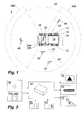
- Fig. 1 shows an inventive piste care vehicle 10, which is used on a ski slope 2.
- the piste care vehicle 10 has a chain drive with two chains 12.
- a snow blower 14 is attached as an example to improve the quality of the piste. Additionally or alternatively, further cultivation units not described here in detail may be provided on the vehicle.
- Said snowthrower 14 comprises a fast-rotating roller, not shown in the figure, which whirls up the snow compressed by the chain and then presses down the snow that has been whirled up by a smoothing press 16, also called a "finisher", to a runway with a homogeneous surface.
- the danger is less of the kinetic energy with which, for example, skiers could bounce against the chains 12 or the snowblower 14. Rather, the danger is that by the enormous forces acting on the chains 12 during the driving of the vehicle 10, and the high energy with which the roller of the snowthrower 14 is driven, persons who are in contact with the chains 12 or reach the snowthrower 14, carry heavy damage to their limbs.
- the piste grooming vehicle 10 has a Fig. 2 with respect to its functional sequence schematically illustrated security system 30.
- This security system 30 has a radar device 32 as well as forward and backward thermal imagers 34a, 34b.
- the radar system 32 is able to monitor the piste grooming vehicle 10 on all sides and to detect moving persons in the monitored area 32 '.
- the thermal imaging cameras 34a, 34b only monitor areas 34a ', 34b' in front of and behind the vehicle 10 and, in addition to the persons 40, 42, 44 that can already be detected by the radar device 32, also recognize persons who, like the person 46 lying in the snow or even covered by a layer of snow. In this way, both stationary persons, who could be rolled over by the vehicle 10 in the event of non-recognition, as well as persons moving, who could just come into contact with the chains 12 or the snowthrower 14 due to their movement, are detected by the radar device 32 and the thermal imaging cameras 34a, 34b reliably recorded together.
- Fig. 2 illustrates the operation of the security system 30.
- the core of the security system 30 is an evaluation unit 36 in the form of a microcomputer.
- the evaluation unit 36 is thereby able to detect whether persons lie in front of or behind the vehicle in the snow. Furthermore, the evaluation unit is able, via the evaluation of the radar system 32, to recognize the moving skiers 40, 42, 44 and to extrapolate their movement path.
- the signal is output to outputs of the evaluation unit 36.
- the evaluation unit 36 in the in Fig. 2 clarified manner emit a warning signal, for example, on a screen 38, stop the track drive, so that the chains 12 come to a standstill, and / or disable the snowthrower 14.
- the evaluation device 36 respond as follows.
- the skier 40 is not at risk because of his distance to the vehicle 10 and because of his extrapolated travel path 40 '. Thus, although detected by the radar device 32 of this skier, he does not trigger any outward reaction of the evaluation device 36.
- the skier 42 is not endangered in itself, since on the basis of his extrapolated travel path 42 'no collision with the vehicle 10 is to be feared. Since he only A few meters away from the vehicle moves and a sudden change in direction of the skier 42 can not be excluded, even this skier 42 would be at least a visual message on the screen 38 in the in Fig. 2 clarified way lead.
- the skier 44 is in acute danger because his extrapolated travel path 44 'leads directly in the area of the right-hand chain 12. In such a situation, the evaluation device 36 would immediately stop the track drive and thus cause the stoppage of the chains 12. Due to the fact that the chain drive of the vehicle 10 is hydrodynamically driven, this standstill occurs very quickly even without a separate emergency brake, so that in the present embodiment, the chains 12 are stationary after a maximum of one second. Equally important is the immediate deactivation of the snowthrower 14, in particular since the critical situation in which the skier 44 is located can lead to it reaching the area of the snowthrower 14 during an evasive maneuver.
- the detection of the snow skier 46 would immediately deactivate the track drive with the chains 12 and thus cause the vehicle 10 to stop to prevent the skier 46 from being overrun by the piste grooming vehicle 10.
- the output data of the sensor device with the radar device 32 and the thermal imaging cameras 34a, 34b serve not only the security system. They are also used in a manner not shown, in order to be displayed in combination with an environment capturing the camera image on a screen in the cockpit and thus serve the visual enhancement. As a result, for example, not identifiable by the camera slope limits, obstacles and the like in the representation of the camera image can be highlighted.
- FIGS. 3 4a and 4b illustrate the mode of operation of a piste grooming vehicle according to the invention by means of a further example.
- FIG. 3 is located in forward drive slope care vehicle 10 in the situation shown here in the area of a steep slope 60 and moves in the direction of the demolition edge 62 of this slope 60. Furthermore, is also in the situation of FIG. 3 a skier 48 in the vicinity of the vehicle.
- Piste care vehicle 10 shown has in the region of a cabin roof of the driver's cab a forward-facing camera 31, which detects an image which corresponds approximately to the image visible to the driver with the naked eye. Furthermore, each aligned in the direction of travel, a laser sensor device 33 and an infrared sensor device 34 is provided on the cab roof, wherein the laser sensor device 33 is used by means of one or more laser beams 72a-72d for detecting the environment. This laser sensor device 33 is designed to measure the distance along approximately horizontally aligned measuring strips 70a to 70d of points on these gauges opposite the vehicle. This is done, for example, by determining the light transit time by detecting the reflected light signal. The in the FIG. 3 illustrated laser beams 72a to 72d illustrate the principle.
- FIG. 4a shows the type of visualization in good visibility conditions. As in FIG. 4a is indicated, all relevant environmental conditions for the vehicle driver are already clearly visible on the basis of the image data captured by the camera 31, so that the risk to the vehicle 10 and the driver is low.
- the additional insertion of information from the laser sensor device 33 for the driver is a help by means of example red highlighted points 62a ', 62b', 62c 'illustrates the driver where in the strip-shaped measuring areas 70a to 70d the Laser sensor device has detected a jump in the detected distance or even a failure of a reflection signal. Since this is the case in the area of the demolition edge 62, the driver is made easier to localize.
- the sensor data and their visualization especially in poor visibility, for example in heavy snow driving, a special meaning. If the environment for the driver when looking through the windshield then barely detectable and the information of the camera 31 are restricted to the same extent, the laser sensor device 33 and the infrared sensor device 34 can still provide information about possible danger spots in the vicinity of the vehicle, be it demolition edges 62 or persons 48. In the case completely restricting the view, the information captured by the sensor devices 33, 34 still remains on the screen 54.
- the camera 31 or an additional camera can furthermore be designed as a thermal imaging camera. This can be used to record the temperature of the substrate. It has been shown that this temperature is increased by working the substrate, so that a thermal imaging camera allows the driver to determine even in dense snow, which areas of the substrate have already been processed. If appropriate, the corresponding information can likewise be superimposed on the image of the outside camera 31.
Abstract
Description
Die Erfindung betrifft ein Pistenpflegefahrzeug mit einem Kettenantrieb und/oder mindestens einem Anbauaggregat zur Bearbeitung eines Untergrundes.The invention relates to a piste grooming vehicle with a chain drive and / or at least one cultivation unit for processing a substrate.
Derartige Pistenpflegefahrzeuge weisen üblicherweise einen Kettenfahrantrieb mit zwei Ketten auf, die auf Skipisten zur Fortbewegung des Fahrzeuges besonders gut geeignet sind. Solche Pistenpflegefahrzeuge weisen häufig auch Anbauaggregate wie insbesondere Schneefräsen auf, die insbesondere am Heck des Fahrzeuges angebracht sind und der Bearbeitung der Schneefläche dienen. Vergleichbare Anbauaggregate sind jedoch auch aus anderen Bereichen bekannt, beispielsweise von gattungsgemäßen Strandpflegefahrzeugen, bei denen die Anbauaggregate der Aufnahme von Sand dienen, um Verunreinigungen aus diesem zu beseitigen.Such piste maintenance vehicles usually have a chain drive with two chains, which are particularly well suited to ski trails for locomotion of the vehicle. Such piste maintenance vehicles often also have cultivation units such as in particular snow blowers, which are mounted in particular at the rear of the vehicle and are used to process the snow surface. However, comparable cultivation units are also known from other fields, for example of generic beach care vehicles, in which the cultivation units serve to receive sand to eliminate impurities from this.
Bei den genannten Pistenpflegepflegefahrzeugen liegt eine besondere Problematik darin, dass diese Fahrzeuge mitunter in unmittelbarer Nähe zu Personen eingesetzt werden, denen die von einem Kettenfahrantrieb oder von Anbauaggregaten ausgehenden Gefahren nicht bewusst sind. Dies gilt insbesondere für Skifahrer und Snowboardfahrer, die ihrem Sport in der Nähe der Pistenpflegefahrzeuge nachgehen. Der Kettenfahrantrieb bzw. die beschriebenen Anbauaggregate können dem Wesen nach konstruktiv nur sehr schwer gekapselt werden, so dass die Gefahr besteht, dass die genannten Personen in Kontakt mit dem Kettenfahrwerk oder mit insbesondere rotierenden Teilen von Anbauaggregaten kommen und durch diese zu Schaden kommen.In the aforementioned grooming care vehicles, a particular problem is that these vehicles are sometimes used in close proximity to people to those of a chain drive or are unaware of any hazards arising from mounted aggregates. This is especially true for skiers and snowboarders doing their sport near the piste grooming vehicles. The chain traction drive or the cultivation units described can be structurally very difficult to encapsulate, so that there is a risk that the persons mentioned come into contact with the tracked or with particular rotating parts of cultivation units and come through this damage.
Aus dem Bereich der Personenkraftwagen ist es bekannt, Sensoren zu verwenden, um Fußgänger zu erfassen, so dass der Fahrer dieser Personenkraftwagen rechtzeitig auf die Fußgänger aufmerksam gemacht wird, um sein Fahrzeug mit der dadurch gebotenen Vorsicht zu führen. Aus dem Bereich der Personenkraftwagen ist es darüber hinaus auch bekannt, dass Fahrzeuge mittels Sensoren einen kurz bevorstehenden Crash mit einem anderen Fahrzeug vorhersehen und in Reaktion darauf ein Bremsmanöver einleiten, um den Crash zu verhindern.From the field of passenger cars, it is known to use sensors to detect pedestrians, so that the driver of these cars is made aware of pedestrians in time to guide his vehicle with the necessary care. Moreover, it is also known from the field of passenger vehicles that vehicles by means of sensors anticipate an imminent crash with another vehicle and, in response, initiate a braking maneuver in order to prevent the crash.
Anders als bei Personenkraftwagen liegt aufgrund der üblicherweise geringen Geschwindigkeit der gattungsgemäßen Pistenpflegefahrzeugen die Gefahrenquelle bei diesen nicht in der Geschwindigkeit des Fahrzeugs selbst, sondern stattdessen in der von außen zugänglichen Gestaltung des Kettenfahrwerks und/oder des Anbauaggregats in Verbindung mit der zum Teil hohen Geschwindigkeit von Personen. Da im Falle der Pistenpflegefahrzeuge üblicherweise die Bewegung dieser Personen, beispielsweise von Skifahrern, signifikant höher als die Geschwindigkeit des Pistenpflegefahrzeuges ist, ist das aus dem PKW-Bereich bekannte oben genannte Crashvermeidungs-System zunächst zwecklos, denn es liegt üblicherweise nicht in der Macht des Fahrzeugs bzw. seines Fahrzeugführers, einen Crash zu verhindern.Unlike passenger cars due to the usually low speed of the generic snow grooming vehicles, the source of danger in these not in the speed of the vehicle itself, but instead in the externally accessible design of the track and / or the attachment in conjunction with the sometimes high speed of people , Since, in the case of piste maintenance vehicles, the movement of these persons, for example skiers, is usually significantly higher than the speed of the piste care vehicle, the above-mentioned crash avoidance system known from the passenger car field is at first useless, because it usually does not lie in the power of the vehicle or his driver, to prevent a crash.
Weiterhin besteht bei gattungsgemäßen Pistenpflegefahrzeugen die Problematik, dass diese bestimmungsgemäß auf Gelände abseits der Straßen eingesetzt werden. Hier kann es für den Fahrzeugführer schwer werden, Gefahren, die durch schwer einsehbares unebenes Gelände entstehen, richtig einzuschätzen. Dies gilt in besonderem Maße für Pistenpflegefahrzeuge, da diese häufig bei widrigen Wetterbedingungen in Form starken Schneetreibens betrieben werden, so dass Gefahren nur schwer erkennbar sind.Furthermore, there is the problem in generic piste maintenance vehicles that they are intended to be used on off-road terrain. Here it can be difficult for the driver to properly assess hazards that arise due to difficult to see uneven terrain. This is especially true for piste maintenance vehicles, as they are often operated in adverse weather conditions in the form of heavy snow driving, so that hazards are difficult to see.
Aufgabe der Erfindung ist es, ein gattungsgemäßes Pistenpflegefahrzeug dahingehend weiterzubilden, dass die Gefahr von schweren Verletzungen im Zusammenhang mit dem Kettenfahrantrieb und/oder den Arbeitsaggregaten vermindert wird und/oder dass die Gefahr für den Fahrzeugführer und das Fahrzeug verringert wird, die sich aus gefährlichen Bodenkonturen wie Spalten und Abhängen ergibt.The object of the invention is to develop a generic piste care vehicle to the effect that the risk of serious injury in connection with the chain drive and / or the power packs is reduced and / or that the risk to the driver and the vehicle is reduced, resulting from dangerous ground contours like columns and slopes.
Erfindungsgemäß ist vorgesehen, dass ein gattungsgemäßes Pistenpflegefahrzeug ein Sicherheitssystem aufweist, welches eine Sensoreinrichtung zur Erfassung von Personen und/oder von Bodenkonturen in der Umgebung des Fahrzeugs aufweist und welches dafür ausgebildet ist, den Kettenfahrantrieb und/oder das Anbauaggregat bei Erfassung einer hierdurch gefährdeten Person zu deaktivieren. Alternativ oder zusätzlich ist das Sicherheitssystem dafür ausgebildet, ein optisches oder akustisches Warnsignal abzugeben, sofern eine durch das Fahrzeug gefährdete Person erfasst wird, wobei das Warnsignal derart ausgebildet ist, dass es durch die gefährdete Person erfassbar ist. Auch kann das Fahrzeug dafür ausgebildet sein, die erfassten Bodenkonturen und/oder die erfassten Personen visualisiert auf einem Bildschirm im Führerstand des Fahrzeugs anzuzeigen.According to the invention, a generic piste grooming vehicle has a safety system which has a sensor device for detecting persons and / or ground contours in the surroundings of the vehicle and which is designed to secure the chain drive and / or the cultivating unit upon detection of a person endangered thereby deactivate. Alternatively or additionally, the security system is designed to emit an optical or audible warning signal if a person at risk of the vehicle is detected, wherein the warning signal is designed such that it can be detected by the person at risk. Also, the vehicle may be configured to display the detected ground contours and / or the detected persons visualized on a screen in the cab of the vehicle.
Ein erfindungsgemäßes Pistenpflegefahrzeug ist demnach durch die Sensoreinrichtung dazu befähigt, automatisiert den Kettenfahrantrieb und/oder das Anbauaggregat zu deaktivieren, um die Schädigung von Personen zu vermeiden, die in Kontakt mit dem Kettenfahrantrieb oder dem Anbauaggregat gelangen könnten. Die Gemeinsamkeit des Kettenfahrantriebs und des Anbauaggregats, die von außen offen zugänglichen bewegten Teile auf geringer Höhe über dem Boden, werden hinsichtlich ihrer Gefahr dadurch entschärft, dass sie zum Stillstand gebracht werden, wenn eine Gefahrensituation droht.A piste grooming vehicle according to the invention is thus enabled by the sensor device to automatically deactivate the chain drive and / or the attachment in order to avoid the injury of persons who might come into contact with the chain drive or the attachment. The commonality of the Kettenfahrantriebs and the growing unit, the externally accessible moving parts at low altitude above the ground, are mitigated in terms of their risk that they are brought to a standstill in a dangerous situation threatens.
Das derart ausgebildete Sicherheitssystem ist demnach nicht primär dafür ausgebildet, einen drohenden Kontakt zu vermeiden, da dies in der Regel aufgrund der geringen Geschwindigkeit des Pistenpflegefahrzeugs und der vergleichsweise hohe Geschwindigkeiten der Personen, insbesondere Skifahrer, ohnehin nicht möglich ist. Stattdessen wird durch die Deaktivierung des Kettenfahrantriebs bzw. der Anbauaggregate die Verletzungsgefahr signifikant gesenkt. Eine Person, insbesondere ein Skifahrer, der mit dem Fahrzeug kollidiert, erleidet somit gegebenenfalls trotz des Sicherheitssystems Schäden durch den Aufprall selbst, es kommt jedoch nicht zu den schweren Verletzungen, die durch Einquetschungen zwischen Kettenband und Kettenrädern oder durch Kontakt mit den rotierenden Teilen einer Schneefräse und ähnlicher Anbauaggregate verursacht werden können.The security system designed in this way is therefore not primarily designed to avoid an impending contact, since this is generally not possible anyway due to the low speed of the piste grooming vehicle and the comparatively high speeds of the persons, in particular skiers. Instead, the risk of injury is significantly reduced by deactivating the chain drive or the attachments. Thus, a person, particularly a skier, who collides with the vehicle may suffer damage from the impact itself, despite the safety system, but will not suffer serious injury from pinching between the chain and sprockets or from contact with the rotating parts of a snowthrower and similar cropping aggregates.
Durch das zusätzliche oder alternative an die Umgebung gerichtete Warnsignal kann eine gefährdete Person, insbesondere ein Skifahrer, gewarnt werden, so dass er ggf. die Kollision noch vermeiden kann. Die Warnung erfolgt beispielsweise über eine Hupe, insbesondere mit einer Lautstärke von mindestens 80 Dezibel, vorzugsweise mindestens 100 Dezibel, oder über eine deutlich erkennbare und starke Warnlampe. Das Sicherheitssystem hat vorzugsweise mehrere mögliche Reaktionsvarianten wie die Deaktivierung des Fahrantriebs, die differenzierte Deaktivierung eines oder mehrerer Anbauaggregate und die Abgabe eines Warnsignals. Vorzugsweise ist das Sicherheitssystem dafür ausgebildet, in Abhängigkeit der erfassten Gefahrenlage die jeweils passenden Reaktionsvarianten auszuwählen, wobei insbesondere auch die derzeitige Fahrsituation (Fahrtrichtung, Neigung des Untergrundes) des Fahrzeugs miteinbezogen werden kann. So ist bei einem talwärts arbeitenden Pistenpflegefahrzeug, in Richtung dessen ein Skifahrer talwärts fährt, die Deaktivierung der heckseitigen Schneefräse geboten, während der Fahrantrieb in Betrieb bleiben kann oder sogar sollte, um die relative Aufprallgeschwindigkeit zu verringern. Das Sicherheitssystem ist vorzugsweise zur Bewirkung einer solchen differenzierten Reaktion ausgebildet.By means of the additional or alternative warning signal directed to the surroundings, an endangered person, in particular a skier, can be warned, so that he can possibly avoid the collision. The warning is for example via a horn, in particular with a volume of at least 80 decibels, preferably at least 100 decibels, or a clearly visible and strong warning lamp. The safety system preferably has several possible reaction variants such as the deactivation of the traction drive, the differentiated deactivation of one or more cultivating units and the delivery of a warning signal. The safety system is preferably designed to select the appropriate reaction variants as a function of the detected danger situation, wherein in particular also the current driving situation (direction of travel, inclination of the ground) of the vehicle can be included. Thus, in a downhill slope grooming vehicle, in the direction of which a skier drives downhill, the deactivation of the rear snow blower is required, while the traction drive can or should remain in operation, in order to reduce the relative impact speed. The security system is preferably designed to effect such a differentiated response.
Weiterhin kann ein erfindungsgemäßes Fahrzeug durch die visualisierte Informationsvermittlung an den Fahrer hinsichtlich in der Umgebung befindlicher Personen oder der Bodenkonturen in der Umgebung des Fahrzeugs eine deutliche Gefahrenverringerung für den Fahrzeugführer und das Fahrzeug erreichen. Der Fahrer kann Personen, die sich im Umfeld des Fahrzeugs aufhalten, durch die auf einem Bildschirm dargestellten Informationen sicher erkennen und entsprechend hierauf reagieren. Insbesondere jedoch kann er durch die Visualisierung der Bodenkonturen die von Abhängen, Spalten und dergleichen ausgehende Gefahren erfassen und zweckmäßig reagieren. Dies ist bei gattungsgemäßen Pistenpflegefahrzeugen von großer Bedeutung, denn diese werden im alpinen Bereich eingesetzt, in dem es sehr plötzliche Änderungen der Witterung erforderlich machen können, das Fahrzeug auch noch führen, wenn das menschliche Auge kaum noch in der Lage ist, Konturen in der Umgebung des Fahrzeugs wahrzunehmen.Furthermore, a vehicle according to the invention can achieve a significant reduction in risk for the driver and the vehicle by virtue of the visualized information transmission to the driver with regard to persons located in the surroundings or the ground contours in the surroundings of the vehicle. The driver can reliably recognize and respond to persons who are in the vicinity of the vehicle by the information displayed on a screen. In particular, however, by visualizing the contours of the ground, he can grasp the dangers arising from slopes, cracks and the like and react appropriately. This is of great importance in generic snow grooming vehicles, because these are used in the alpine area, in which it can make very sudden changes in weather conditions, the vehicle even lead when the human eye is hardly able to contours in the environment of the vehicle.
Insbesondere von Vorteil ist die Erfindung bei einem Pistenpflegefahrzeug mit einer Schneefräse. Gerade eine solche Schneefräse stellt eine besonders hohe Gefahr dar, da die an einer Schneefräse vorgesehene rotierende Walze zwangsläufig nach außen zumindest partiell ungeschützt ist. Es kann sich bei dieser Schneefräse beispielsweise um eine insbesondere heckseitige Schneefräse zur Erzeugung eines homogenen Untergrundes oder um eine insbesondere frontseitige Schneefräse zum Abtransport überschüssigen Schnees handelt. Ebenfalls von Vorteil ist die Erfindung in Hinblick auf ein Anbauaggregat, welches einen Ausleger mit gegenüber einem Hauptkörper des Auslegers angetriebenen beweglichen Bearbeitungselementen zur Herstellung einer Half-Pipe umfasst.Particularly advantageous is the invention in a piste grooming vehicle with a snowblower. Especially such a snowthrower is a particularly high risk, since the provided on a snowblower rotating roller is inevitably at least partially unprotected to the outside. For example, this snowblower may be a snow-blower, in particular at the rear, for producing a homogeneous substrate or a front-side snowblower for removing excess snow. Also advantageous is the invention with regard to an attachment which comprises a boom with respect to a main body of the boom driven movable processing elements for producing a half-pipe.
Die Verwendung an einem Pistenpflegefahrzeug ist weiterhin auch deshalb zweckmäßig, da gerade ein Pistenpflegefahrzeug durch seinen Einsatz im schneebedeckten Gebirge besonderen Gefahren ausgesetzt ist, denen durch eine erfindungsgemäße Ausgestaltung mit einer Sensoreinrichtung zur Erfassung von Bodenkonturen besonders gut begegnet werden kann.The use of a piste grooming vehicle is furthermore also expedient, since it is precisely a piste grooming vehicle which is exposed to particular hazards as a result of its use in the snow-covered mountains, which can be counteracted particularly well by an embodiment according to the invention having a sensor device for detecting ground contours.
Der Kettenfahrantrieb und das Anbauaggregat des Fahrzeugs können beispielsweise durch einen Verbrennungsmotor oder einen Elektromotor angetrieben sein. Besonders von Vorteil ist es jedoch, wenn der Kettenfahrantrieb oder das Anbauaggregat mittels eines Hydromotors angetrieben wird. Ein solcher Hydromotor ist in einen Hydraulikkreislauf mit einer Hydraulikpumpe eingebunden und setzt die über die Hydraulikflüssigkeit zugeführte Energie in mechanische Energie, insbesondere in eine Rotationsbewegung, um. Die Vorteilhaftigkeit der Verwendung eines solchen Hydromotors liegt in der besonderen Eignung zum sofortigen Bremsen. Sobald die Zufuhr von druckbeaufschlagter Hydraulikflüssigkeit unterbunden wird, kommen der Kettenfahrantrieb oder das Anbauaggregat unmittelbar zum Stillstand, ohne dass es separater Bremseinrichtungen bedarf.The chain drive and the attachment of the vehicle can be driven for example by an internal combustion engine or an electric motor. It is particularly advantageous, however, if the chain drive or the attachment is driven by a hydraulic motor. Such a hydraulic motor is integrated into a hydraulic circuit with a hydraulic pump and converts the energy supplied via the hydraulic fluid into mechanical energy, in particular into a rotational movement. The advantage of using such a hydraulic motor is the particular suitability for immediate braking. Once the supply of pressurized hydraulic fluid is prevented, come Chain drive or the attachment immediately to a standstill, without the need for separate braking devices.
Zur Erfassung von Personen und Bodenkonturen in der Umgebung des Pistenpflegefahrzeug umfasst die Sensoreinrichtung vorzugsweise eine Infrarotsensoreinrichtung, eine Lasersensoreinrichtung und/oder eine Radareinrichtung.For detecting persons and ground contours in the vicinity of the runway care vehicle, the sensor device preferably comprises an infrared sensor device, a laser sensor device and / or a radar device.
Neben anderen bekannten Sensoreinrichtungen werden insbesondere diese Varianten als besonders vorteilhaft angesehen. Bei der Infrarotsensoreinrichtung handelt es sich vorzugsweise um eine Wärmebildkamera, die Personen auch erfassen kann, wenn diese sich nicht bewegen und beispielsweise nach einem Sturz auch für eine Lasersensoreinrichtung oder einer Radareinrichtung schwer zu erfassen sind. Insbesondere kann die Infrarotsensoreinrichtung auch derart ausgebildet/ausgerichtet sein, dass in unmittelbarer Nähe der Schneefläche befindliche oder sogar unter der Schneeoberfläche befindliche Personen erfasst werden. Die Lasersensoreinrichtung kann insbesondere auch als 3D-Lasersensoreinrichtung ausgebildet sein, die die Umgebung dreidimensional erfasst.In addition to other known sensor devices, in particular, these variants are considered to be particularly advantageous. The infrared sensor device is preferably a thermal imaging camera, which can also detect persons when they are not moving and, for example, are difficult to detect after a fall even for a laser sensor device or a radar device. In particular, the infrared sensor device can also be designed / aligned such that persons located in the immediate vicinity of the snow surface or even located below the snow surface are detected. In particular, the laser sensor device can also be designed as a 3D laser sensor device which detects the environment three-dimensionally.
Da die genannten Typen von Sensoreinrichtungen jeweils Vor- und Nachteile haben, sind vorzugsweise mehrere von ihnen gemeinsam an einem Pistenpflegefahrzeug vorgesehen, wobei sie unterschiedliche oder auch überlappende Erfassungsbereiche aufweisen können. Die verschiedenen Typen von Sensoreinrichtungen können mit einer gemeinsamen Auswerteeinheit verbunden werden, die auf Basis der verschiedenen Eingangsdaten ein zuverlässiges Bild von einer möglichen Gefährdung von Personen zum Zwecke der weiteren Auswertung zeichnen kann.Since the aforementioned types of sensor devices each have advantages and disadvantages, preferably several of them are provided together on a piste grooming vehicle, wherein they may have different or even overlapping detection areas. The various types of sensor devices can be connected to a common evaluation unit, which on the basis of the various input data can draw a reliable picture of a possible hazard to persons for the purpose of further evaluation.
Von besonderem Vorteil ist eine Gestaltung, bei der das Pistenpflegefahrzeug eine Infrarotsensoreinrichtung aufweist, deren Erfassungsbereich ausschließlich in Längsrichtung vor und/oder hinter dem Pistenpflegefahrzeug angeordnet ist und neben dem Fahrzeug einen toten Winkel aufweist, und wobei weiterhin das Pistenpflegefahrzeug eine Lasersensoreinrichtung, insbesondere eine 3D-Lasersensoreinrichtung, und/oder eine Radareinrichtung aufweist, deren Erfassungsbereich zumindest in Fahrzeugquerrichtung neben dem Pistenpflegefahrzeug angeordnet ist.Of particular advantage is a design in which the piste grooming vehicle has an infrared sensor device whose detection area is arranged exclusively in the longitudinal direction in front of and / or behind the piste grooming vehicle and has a blind spot next to the vehicle, and wherein the piste grooming vehicle further comprises a laser sensor device, in particular a 3D sensor. Laser sensor device, and / or a radar device whose detection range is arranged at least in the vehicle transverse direction next to the piste grooming vehicle.
Eine solche Anordnung ermöglicht es, die Infrarotsensoreinrichtung lediglich auf Erfassungsbereiche zu richten, die vom Fahrzeug während seiner Fahrbewegung erreicht werden, um in diesen Bereichen auch die Verletzung von beispielsweise im Schnee liegenden oder aus anderen Gründen durch eine Radareinrichtung oder einer Lasersensoreinrichtung nicht erfassbare Personen zuverlässig zu erkennen. Die Lasersensoreinrichtung oder die Radareinrichtung erfasst zusätzlich dazu die Seitenbereiche des Fahrzeuges, so dass sich dort bewegende Personen erfasst werden können. In den Seitenbereichen liegende Personen, die lediglich für die Infrarotsensoreinrichtung erfassbar wären, sind für das Sicherheitssystem nicht von Interesse, da sie nicht gefährdet sind.Such an arrangement makes it possible to direct the infrared sensor device only to detection areas, which are achieved by the vehicle during its driving movement to reliably in these areas, the injury of lying for example in the snow or other reasons by a radar device or a laser sensor device people detect. The laser sensor device or the radar device additionally detects the side areas of the vehicle, so that people moving there can be detected. Persons lying in the side areas, which would only be detectable for the infrared sensor device, are not of interest for the safety system since they are not endangered.
Insbesondere hinsichtlich der sich bewegenden Personen ist es von Vorteil, wenn die Auswerteelektronik deren Bewegungspfad extrapoliert, um zu erfassen, ob diese Personen mit dem Pistenpflegefahrzeug in Kontakt kommen könnten.In particular, with regard to the moving people, it is advantageous if the transmitter extrapolates their movement path to detect whether these people could come into contact with the piste grooming vehicle.
Die Auswerteelektronik der Steuereinrichtung ist dafür ausgebildet, den Kettenfahrantrieb oder das Anbauaggregat bei einer Personengefährdung zu deaktivieren. Vorzugsweise ist das Sicherheitssystem weiterhin dafür ausgebildet, eine audiovisuelle Warnmitteilung an den Fahrzeugführer abzugeben, beispielsweise in Form eines Warntons oder aber einer Einblendung auf der Instrumententafel oder einem Bildschirm des Fahrzeugs. Vorzugsweise erfolgt eine derartige audiovisuelle Warnmitteilung bereits bei einem geringeren Grad einer Personengefährdung, so dass eine sich zuspitzende Gefahrenlage zunächst lediglich mit einer derartigen audiovisuellen Warnmitteilung einhergeht und erst im Zuge der Zuspitzung die Deaktivierung des Kettenfahrantriebs und/oder des Anbauaggregats erfolgt. Eine solche Gestaltung gestattet es somit beispielsweise dem Fahrzeugführer des Pistenpflegefahrzeug, selbsttätig auf die Gefahrenlage einzugehen.The evaluation of the controller is designed to disable the chain drive or the attachment in a personal hazard. Preferably, the security system is further adapted to be audiovisual Issue warning message to the driver, for example in the form of a warning tone or a display on the instrument panel or a screen of the vehicle. Such an audiovisual warning message preferably takes place even at a lower degree of danger to a person, so that an escalating danger situation initially only accompanies such an audiovisual warning message and the deactivation of the chain drive and / or the attachment occurs only in the course of the tapering. Such a design thus allows, for example, the driver of the piste grooming vehicle to respond automatically to the danger situation.
Von besonderem Vorteil ist es, wenn das Fahrzeug eine Kamera zur optischen Erfassung der Umgebung aufweist, wobei das von dieser Kamera erfasste Bild auf dem Bildschirm im Führerstand angezeigt wird und wobei das auf dem Bildschirm dargestellte Bild um durch die Sensoreinrichtung erfasste Informationen ergänzt wird. Durch diese Gestaltung wird erreicht, dass dem Fahrzeugführer mögliche Gefahrenquellen in besonders anschaulicher Art und Weise verdeutlicht werden können, da diese direkt und an der korrekten Stelle in das Bild der Außenkamera eingeblendet werden, welches in etwa mit dem Blick des Fahrzeugführers durch die Windschutzscheibe übereinstimmt. Der Fahrer kann dadurch Personen oder mögliche durch die Bodenkonturen verursachte Gefahren gut lokalisieren. Hierdurch ist es dem Fahrzeugführer weiterhin möglich, auch bei widrigen Wetterbedingungen, wie insbesondere bei Schneetreiben, derartige Gefahrenquellen zu erkennen.It is particularly advantageous if the vehicle has a camera for optical detection of the environment, wherein the image captured by this camera is displayed on the screen in the cab and wherein the image displayed on the screen is supplemented by information detected by the sensor device. By this design is achieved that the driver possible sources of danger can be illustrated in a particularly vivid manner, as they are displayed directly and at the correct location in the image of the outdoor camera, which corresponds approximately to the view of the driver through the windshield. The driver can thereby well locate persons or possible hazards caused by the ground contours. As a result, it is still possible for the driver to recognize such sources of danger even in adverse weather conditions, such as in particular when driving snow.
Die eingeblendeten Informationen können dabei insbesondere von einer Infrarotsensoreinrichtung oder einer Lasersensoreinrichtung stammen. Informationen der Infrarotsensoreinrichtung werden dabei vorzugsweise derart verarbeitet, dass die hierdurch erfassten Wärmequellen an der jeweils passenden Stelle in das Kamerabild eingeblendet werden, beispielsweise in Form roter Punkte oder dergleichen.The information displayed can originate in particular from an infrared sensor device or a laser sensor device. Information of the infrared sensor device are preferably processed such that the thus detected heat sources are displayed at the appropriate location in the camera image, for example in the form of red dots or the like.
Bei der Verwendung einer Lasersensoreinrichtung in diesem Kontext ist es von Vorteil, wenn die von dieser Lasersensoreinrichtung erfassten Bodenkonturen im auf dem Bildschirm dargestellten Bild eingeblendet werden. So können insbesondere auf dem Fahrweg bestehende Hindernisse wie beispielsweise Bäume oder Felsen von der Lasersensoreinrichtung erfasst werden und an der jeweils korrespondierenden Stelle im Bild der Kamera eingeblendet werden. Besonders von Vorteil ist es jedoch, wenn die Lasersensoreinrichtung dafür verwendet wird, Gefahrenstellen im Untergrund zu visualisieren. So können insbesondere Spalten im Boden sowie Abhänge und Abbrüche an den korrespondieren Stellen im Kamerabild eingeblendet werden. Vorzugsweise erfolgt diese Einblendung in einer Signalfarbe wie Rot, so dass sie sich deutlich von dem in der Kamera erfassten Bild abhebt.When using a laser sensor device in this context, it is advantageous if the ground contours detected by this laser sensor device are superimposed in the image displayed on the screen. Thus, in particular on the track existing obstacles such as trees or rocks can be detected by the laser sensor device and displayed at the respective corresponding point in the image of the camera. However, it is particularly advantageous if the laser sensor device is used to visualize danger spots in the underground. In particular, gaps in the floor as well as slopes and breaks at the corresponding points in the camera image can be displayed. Preferably, this insertion takes place in a signal color such as red, so that it stands out clearly from the image captured in the camera.
Eine besonders vorteilhafte Gestaltung sieht dabei vor, dass die Lasersensoreinrichtung dafür ausgebildet ist, entlang einer Mehrzahl von sich linienförmig erstreckenden Messbereichen vor dem Pistenpflegefahrzeug die Entfernung eines Untergrundes zu erfassen, wobei im auf dem Bildschirm dargestellten Bild jene Punkte entlang dieser Messbereiche optisch besonders hervorgehoben werden, an denen ein Sprung in der erfassten Entfernung zu verzeichnen ist.A particularly advantageous embodiment provides that the laser sensor device is designed to detect the removal of a substrate along a plurality of linearly extending measuring areas in front of the piste grooming vehicle, wherein those points are visually particularly highlighted in the image displayed on the screen, where there is a jump in the detected distance.
Bei dieser Gestaltung kann somit eine Lasersensoreinrichtung Verwendung finden, die keine vollständige dreidimensionale Erfassung des Bereichs vor dem Fahrzeug bietet, sondern lediglich entlang mehrerer streifenförmiger oder linienförmiger Messbereiche die Distanz zum Untergrund misst. Wenn in einem dieser Messbereiche ein plötzlicher Sprung in der Entfernung zu verzeichnen ist, beispielsweise um mehr als 3m oder um mehr als 5m, so ist dies ein Punkt, auf den der Fahrzeugführer hingewiesen werden sollte. Wenn beispielsweise der Laserstrahl so ausgerichtet ist, dass er den Untergrund vor dem Fahrzeug in etwa 15 Meter Entfernung trifft bzw. unter der Annahme eines ebenen Untergrundes treffen sollte, so stellt es eine potentielle Gefahrensituation dar, wenn nur in einem Teilbereich dieser etwa 15 Meter vor dem Fahrzeug befindlichen gedachten Linie ein Reflektionssignal zu erfassen ist, während über einen Teilabschnitt dieser Linie ein solches Reflektionssignal nicht mehr erfassbar ist oderanhand der Laufzeit des Signals berechnet - aus einer Distanz von deutlich über 15 Meter, beispielsweise aus einer Distanz von 50 Metern kommt. Dies ist ein Indiz dafür, dass hier eine Unstetigkeit im Untergrund vorhanden ist, die für das Fahrzeug eine Gefahr darstellen kann.In this configuration, a laser sensor device can thus be used which does not provide complete three-dimensional detection of the area in front of the vehicle, but merely measures the distance to the ground along several strip-shaped or linear measuring areas. If in one of these measuring ranges a sudden jump in the distance, for example by more than 3m or more than 5m, this is a point to which the driver should be alerted. If, for example, the laser beam is aligned in such a way that it meets the ground in front of the vehicle at a distance of about 15 meters or should hit on the assumption of a level surface, it represents a potential danger situation if only in a subarea of this approximately 15 meters A reflection signal is to be detected on the imaginary line located on the vehicle, while such a reflection signal is no longer detectable over a subsection of this line or calculated on the basis of the transit time of the signal - coming from a distance of well over 15 meters, for example from a distance of 50 meters. This is an indication that there is a discontinuity in the ground, which may pose a danger to the vehicle.
Durch die mehreren Messbereiche, die sich vorzugsweise in etwa parallel zueinander vor dem Fahrzeug erstrecken, werden in der Praxis mehrere der genannten Punkte vom System erfasst, die alle einer gemeinsamen Besonderheit im Boden zuzurechnen sind, beispielsweise einer Abbruchkante. Statt der Darstellung nur eines Punktes dieser Abbruchkante je Messbereich, können diese Punkte auch durch interpolierte Linien miteinander verbunden werden, um dem Fahrzeugführer die Umgebung besser zu verdeutlichen. Auch können die durch die Fahrbewegung des Fahrzeugs immer neu hinzukommende Messwerte mit zuvor bereits aufgenommenen Messwerten verknüpft werden, um die Darstellung der Umgebung auf dem Bildschirm besonders aussagekräftig zu machen.As a result of the multiple measuring ranges, which preferably extend approximately parallel to one another in front of the vehicle, in practice a plurality of said points are detected by the system, all of which are attributable to a common feature in the ground, for example a demolition edge. Instead of displaying only one point of this demolition edge per measuring range, these points can also be interconnected by interpolated lines in order to better illustrate the environment to the driver. Also, the measured values that are always added by the driving movement of the vehicle can be linked to previously recorded measured values in order to make the representation of the surroundings on the screen particularly meaningful.
Weitere Aspekte und Vorteile der Erfindung ergeben sich außer aus den Ansprüchen auch aus der nachfolgenden Beschreibung eines bevorzugten Ausführungsbeispiels der Erfindung, welches anhand der Figuren schematisch erläutert wird. Dabei zeigen:
- Fig. 1
- ein erfindungsgemäßes Pistenpflegefahrzeug in einer ersten Betriebssituation,
- Fig. 2
- schematisch die Arbeitsweise der erfindungsgemäßen Sicherheitseinrichtung und
- Fig. 3 und 4a, 4b
- ein erfindungsgemäßes Pistenpflegefahrzeug in einer zweiten Betriebssituation.
- Fig. 1
- an inventive piste grooming vehicle in a first operating situation,
- Fig. 2
- schematically the operation of the safety device according to the invention and
- Fig. 3 and 4a, 4b
- an inventive piste grooming vehicle in a second operating situation.
Sowohl die Ketten 12 des Kettenlaufwerks als auch die Walze der Schneefräse 14 stellen eine erhebliche Gefahr für Personen dar, die in Kontakt mit ihnen kommen. Dabei geht die Gefahr weniger von der kinetischen Energie aus, mit der beispielsweise Skifahrer gegen die Ketten 12 oder die Schneefräse 14 prallen könnten. Vielmehr liegt die Gefahr darin, dass durch die enormen Kräfte, die an den Ketten 12 während des Fahrbetriebs des Fahrzeugs 10 wirken, und die hohe Energie, mit der die Walze der Schneefräse 14 angetrieben wird, Personen, die in Kontakt mit den Ketten 12 oder der Schneefräse 14 gelangen, schwere Schäden an ihren Gliedmaßen davontragen.Both the
Um dies zu verhindern, weist das erfindungsgemäße Pistenpflegefahrzeug 10 ein in
Das Radarsystem 32 ist in der Lage, das Pistenpflegefahrzeug 10 allseitig zu überwachen und im überwachten Bereich 32' sich bewegende Personen zu erkennen. Die Wärmebildkameras 34a, 34b überwachen lediglich Bereiche 34a', 34b' vor und hinter dem Fahrzeug 10 und erkennen dort zusätzlich zu den bereits durch die Radareinrichtung 32 erfassbaren sich bewegenden und aufrechten Personen 40, 42, 44 auch Personen, die sich wie die Person 46 liegend im Schnee befinden oder gar von einer Schneeschicht überdeckt sind. Damit werden sowohl unbewegte Personen, die bei Nichterkennung vom Fahrzeug 10 überrollt werden könnten, als auch sich bewegende Personen, die gerade aufgrund ihrer Bewegung mit den Ketten 12 oder der Schneefräse 14 in Kontakt gelangen könnten, von der Radareinrichtung 32 und den Wärmebildkameras 34a, 34b gemeinsam zuverlässig erfasst.The
In
In Abhängigkeit der erfassten Personen 40 bis 46 und der Auswertung hinsichtlich der Gefährdungslage, erfolgt die Signalabgabe an Ausgänge der Auswerteeinheit 36. Abhängig von der Gefahrensituation kann die Auswerteeinheit 36 in der in
Bezogen auf die Personen 40 bis 46, die in
Der Skifahrer 40 ist aufgrund seiner Entfernung zum Fahrzeug 10 und aufgrund seines extrapolierten Bewegungspfades 40' nicht gefährdet. Obwohl also durch die Radareinrichtung 32 dieser Skifahrer erfasst wird, löst er keinerlei nach außen wirkende Reaktion der Auswerteeinrichtung 36 aus. Der Skifahrer 42 ist zwar an sich auch nicht gefährdet, da bei Zugrundelegung seines extrapolierten Bewegungspfades 42' keine Kollision mit dem Fahrzeug 10 zu befürchten ist. Da er sich jedoch nur wenige Meter neben dem Fahrzeug bewegt und eine plötzliche Richtungsänderung des Skifahrers 42 nicht ausgeschlossen werden kann, würde bereits dieser Skifahrer 42 zumindest zu einer visuellen Mitteilung auf dem Bildschirm 38 in der in
Der Skifahrer 44 ist akut gefährdet, da sein extrapolierter Bewegungspfad 44' unmittelbar in dem Bereich der rechtsseitigen Kette 12 führt. In einer solchen Situation würde die Auswerteeinrichtung 36 unmittelbar das Kettenlaufwerk stoppen und somit den Stillstand der Ketten 12 bewirken. Aufgrund der Tatsache, dass das Kettenlaufwerk des Fahrzeugs 10 hydrodynamisch angetrieben wird, tritt dieser Stillstand auch ohne eine separate Notbremseinrichtung sehr schnell ein, so dass beim vorliegenden Ausführungsbeispiel die Ketten 12 nach maximal einer Sekunde still stehen. Ebenso wichtig ist die sofortige Deaktivierung der Schneefräse 14, insbesondere da die kritische Situation, in der sich der Skifahrer 44 befindet, dazu führen kann, dass dieser bei einem Ausweichmanöver in den Bereich der Schneefräse 14 gelangt.The
Auch die Erfassung des im Schnee liegenden Skifahrers 46 würde unmittelbar eine Deaktivierung des Kettenlaufwerks mit den Ketten 12 und somit einen Stillstand des Fahrzeugs 10 bewirken, um zu verhindern, dass der Skifahrer 46 von dem Pistenpflegefahrzeug 10 überrollt wird.Also, the detection of the
Abhängig von der Gefahrensituation kann es im Einzelfall zumindest zunächst auch ausreichen, über ein nach außen gerichtetes Warnlicht 50 oder eine Warnhupe 52 die gefährdete Person zu warnen, um erst bei fortgesetzter Verschärfung der Gefahrensituation oben genannte Deaktivierung des Kettenfahrantriebs 12 und/oder der Schneefräse 14 einzuleiten.Depending on the danger situation, it may be sufficient in the individual case, at least initially, to warn the endangered person via an outwardly directed
Die Ausgangsdaten der Sensoreinrichtung mit der Radareinrichtung 32 und den Wärmebildkameras 34a, 34b dienen nicht nur dem Sicherheitssystem. Sie werden in nicht näher dargestellter Weise auch genutzt, um kombiniert mit einem die Umgebung erfassenden Kamerabild auf einem Bildschirm im Cockpit angezeigt zu werden und so der Sichtverbesserung zu dienen. Dadurch können beispielsweise durch die Kamera an sich nicht erkennbare Pistenbegrenzungen, Hindernisse und ähnliches in der Darstellung des Kamerabildes besonders hervorgehoben werden.The output data of the sensor device with the
Die
Wie aus
Das in
Die von der Kamera 31, der Infrarotsensoreinrichtung 34 und der Lasersensoreinrichtung 33 erfassten Informationen werden mittels einer Auswerteeinheit in Form eines Computers auf einem Bildschirm 54 im Cockpit visualisiert.
Insbesondere bei dem Anwendungsfall der Pistenpflegefahrzeuge ist dies von großem Wert, da es selbst bei guter Sicht häufig schwierig ist, abzuschätzen, ob weitgehend konturlose weiße Schneeflächen unmittelbar aneinander angrenzen oder durch einen für Mensch und Maschine gefährlichen Abhang oder Spalt voneinander getrennt sind.This is of great value, in particular in the case of use of piste grooming vehicles, since it is often difficult even when visibility is good to see whether largely white skimless snow surfaces directly adjoin one another or are separated from one another by a slope or gap that is dangerous for man and machine.
Wie
Die Kamera 31 oder auch eine zusätzliche Kamera kann weiterhin als Wärmebildkamera ausgebildet sein. Dies kann genutzt werden, um die Temperatur des Untergrundes zu erfassen. Es hat sich gezeigt, dass diese Temperatur sich durch Bearbeitung des Untergrundes erhöht, so dass eine Wärmebildkamera es dem Fahrzeugführer gestattet, auch bei dichtem Schnee festzustellen, welche Bereiche des Untergrundes bereits bearbeitet wurden. Die entsprechende Information kann gegebenenfalls ebenfalls in das Bild der Außenkamera 31 eingeblendet werden.The
Claims (12)
ein Sicherheitssystem (30), welches
a security system (30) which
dadurch gekennzeichnet, dass
das Pistenpflegefahrzeug (10) zumindest
characterized in that
the piste grooming vehicle (10) at least
dadurch gekennzeichnet, dass
der Kettenfahrantrieb (12) und/oder das Anbauaggregat (14) mittels eines Hydromotors angetrieben wird. 3. piste grooming vehicle according to one of the preceding claims,
characterized in that
the chain drive (12) and / or the attachment (14) is driven by a hydraulic motor.
dadurch gekennzeichnet, dass
die Sensoreinrichtung
characterized in that
the sensor device
dadurch gekennzeichnet, dass
characterized in that
dadurch gekennzeichnet, dass
das Sicherheitssystem (30) dafür ausgebildet ist, vor Deaktivierung des Kettenfahrantriebs (12) oder des Anbauaggregats (14) eine audiovisuelle Warnmitteilung an einen Fahrzeugführer abzugeben. 6. piste grooming vehicle according to one of the preceding claims,
characterized in that
the safety system (30) is designed to prevent the chain drive (12) or the Growing unit (14) to issue an audiovisual warning message to a driver.
dadurch gekennzeichnet, dass
das Pistenpflegefahrzeug eine Kamera zur optischen Erfassung der Umgebung aufweist, wobei das von dieser Kamera erfasste Bild auf dem Bildschirm im Führerstand angezeigt wird und wobei das auf dem Bildschirm dargestellte Bild um durch die Sensoreinrichtung erfasste Informationen ergänzt wird. 7. piste grooming vehicle according to one of the preceding claims,
characterized in that
the piste grooming vehicle has a camera for optically detecting the environment, wherein the image captured by this camera is displayed on the screen in the driver's cab, and wherein the image displayed on the screen is supplemented with information acquired by the sensor device.
dadurch gekennzeichnet, dass
die Sensoreinrichtung mindestens eine Infrarotsensoreinrichtung aufweist und die mittels der Infrarotsensoreinrichtung erfasste Wärmequellen im auf dem Bildschirm dargestellten Bild eingeblendet werden. 8. piste grooming vehicle according to claim 7,
characterized in that
the sensor device has at least one infrared sensor device and the heat sources detected by means of the infrared sensor device are superimposed in the image displayed on the screen.
dadurch gekennzeichnet, dass
die Sensoreinrichtung mindestens eine Lasersensoreinrichtung aufweist und die von dieser Lasersensoreinrichtung erfassten Bodenkonturen im auf dem Bildschirm dargestellten Bild eingeblendet werden. 9. piste grooming vehicle according to claim 7 or 8,
characterized in that
the sensor device has at least one laser sensor device and the ground contours detected by this laser sensor device are superimposed in the image displayed on the screen.
dadurch gekennzeichnet, dass
die Lasersensoreinrichtung dafür ausgebildet ist, entlang einer Mehrzahl von sich linienförmigen erstreckenden Messbereichen vor dem Pistenpflegefahrzeug die Entfernung eines Untergrundes von zu erfassen, wobei im auf dem Bildschirm dargestellten Bild jene Punkte entlang dieser Messbereich optisch besonders hervorgehoben werden, an denen ein Sprung in der erfassten Entfernung zu verzeichnen ist. 10. piste grooming vehicle according to claim 9,
characterized in that
the laser sensor device is designed to detect the removal of a background surface along a plurality of line-shaped measuring areas in front of the piste care vehicle, wherein in the image displayed on the screen those points along this measuring area are optically particularly be highlighted, in which a jump in the detected distance is recorded.
dadurch gekennzeichnet, dass
eine Auswerteeinheit (36) des Sicherheitssystems dafür ausgebildet ist, eine erfasste Gefahrensituation derart zu kategorisieren, dass in Abhängigkeit der Gefahrensituation eine der Maßnahmen
characterized in that
an evaluation unit (36) of the safety system is designed to categorize a detected hazard situation such that, depending on the dangerous situation, one of the measures
dadurch gekennzeichnet, dass
eine Auswerteeinheit (36) des Sicherheitssystems dafür ausgebildet ist, anhand einer erfassten Gefahrensituation zu prüfen, von welchem Anbauaggregat (14) Gefahr ausgeht bzw. ob vom Kettenfahrantrieb (12) Gefahr ausgeht, und in Reaktion hierauf nur die die gefährdenden Anbauaggregate (14) und/oder den gefährdenden Kettenantrieb (12) zu deaktivieren. 9. piste grooming vehicle according to one of the preceding claims,
characterized in that
an evaluation unit (36) of the safety system is designed to check on the basis of a detected hazard situation, from which mounting unit (14) risk or if the chain drive (12) danger, and in response thereto only the endangered cultivation units (14) and / or disable the hazardous chain drive (12).
Applications Claiming Priority (1)
| Application Number | Priority Date | Filing Date | Title |
|---|---|---|---|
| DE102010007603A DE102010007603A1 (en) | 2010-02-05 | 2010-02-05 | working vehicle |
Publications (2)
| Publication Number | Publication Date |
|---|---|
| EP2354316A1 true EP2354316A1 (en) | 2011-08-10 |
| EP2354316B1 EP2354316B1 (en) | 2012-11-07 |
Family
ID=43919868
Family Applications (1)
| Application Number | Title | Priority Date | Filing Date |
|---|---|---|---|
| EP11153413A Active EP2354316B1 (en) | 2010-02-05 | 2011-02-04 | Piste maintenance vehicle |
Country Status (2)
| Country | Link |
|---|---|
| EP (1) | EP2354316B1 (en) |
| DE (1) | DE102010007603A1 (en) |
Cited By (3)
| Publication number | Priority date | Publication date | Assignee | Title |
|---|---|---|---|---|
| EP3633107A1 (en) * | 2018-10-05 | 2020-04-08 | Kässbohrer Geländefahrzeug AG | Ski trail maintenance vehicle and method for operating same |
| CN111204378A (en) * | 2018-11-21 | 2020-05-29 | 普瑞诺斯股份公司 | Tracked vehicle for ski tracks and method for displaying information for such a tracked vehicle |
| US11970828B2 (en) | 2018-10-05 | 2024-04-30 | Kässbohrer Geländefahrzeug AG | Method for operating a piste grooming vehicle |
Families Citing this family (4)
| Publication number | Priority date | Publication date | Assignee | Title |
|---|---|---|---|---|
| DE202013100480U1 (en) * | 2013-02-01 | 2014-05-05 | EiFo Forsttechnik GmbH | Winch arrangement |
| DE102018213239A1 (en) * | 2018-08-07 | 2020-02-13 | Kässbohrer Geländefahrzeug AG | Snow groomer with a chain drive |
| US11320830B2 (en) | 2019-10-28 | 2022-05-03 | Deere & Company | Probabilistic decision support for obstacle detection and classification in a working area |
| DE102021201598A1 (en) * | 2021-02-19 | 2022-08-25 | Kässbohrer Geländefahrzeug Aktiengesellschaft | Snow groomer with at least one snow groomer |
Citations (7)
| Publication number | Priority date | Publication date | Assignee | Title |
|---|---|---|---|---|
| DE4120596A1 (en) * | 1990-06-21 | 1992-01-02 | Caterpillar Mitsubishi Ltd | WARNING DEVICE FOR A CONSTRUCTION MACHINE |
| US20020190849A1 (en) * | 2001-06-19 | 2002-12-19 | Orzechowski Jeffery R. | Industrial vehicle safety system |
| GB2400712A (en) * | 2003-02-28 | 2004-10-20 | Mervyn George Edward Brodie | A radar safety system for detecting workmen within a danger area |
| EP1255895B1 (en) * | 2000-02-03 | 2005-09-14 | Per Eriksson | Working device |
| DE102004040136A1 (en) * | 2004-08-19 | 2006-03-09 | Abg Allgemeine Baumaschinen-Gesellschaft Mbh | Device for milling traffic areas |
| US7141796B2 (en) * | 2001-10-29 | 2006-11-28 | Honda Giken Kogyo Kabushiki Kaisha | Vehicle information providing apparatus |
| DE102006040537A1 (en) * | 2006-08-30 | 2008-03-13 | Deutsches Zentrum für Luft- und Raumfahrt e.V. | Motor vehicle e.g. passenger car, assistance system, has sensor for detecting relevant road user e.g. pedestrian, located in surrounding of vehicle, where system determines and reproduces traffic conditions based on detected road user |
Family Cites Families (2)
| Publication number | Priority date | Publication date | Assignee | Title |
|---|---|---|---|---|
| EP1309882B1 (en) * | 2000-08-16 | 2004-12-08 | Raytheon Company | Near object detection system |
| DE10244822A1 (en) * | 2002-09-26 | 2004-04-08 | Deere & Company, Moline | Safety monitoring system for agricultural harvesting machine in field has sensor on front of cab connected to antenna receiving signals from geostationary satellite and connected to control module |
-
2010
- 2010-02-05 DE DE102010007603A patent/DE102010007603A1/en not_active Ceased
-
2011
- 2011-02-04 EP EP11153413A patent/EP2354316B1/en active Active
Patent Citations (7)
| Publication number | Priority date | Publication date | Assignee | Title |
|---|---|---|---|---|
| DE4120596A1 (en) * | 1990-06-21 | 1992-01-02 | Caterpillar Mitsubishi Ltd | WARNING DEVICE FOR A CONSTRUCTION MACHINE |
| EP1255895B1 (en) * | 2000-02-03 | 2005-09-14 | Per Eriksson | Working device |
| US20020190849A1 (en) * | 2001-06-19 | 2002-12-19 | Orzechowski Jeffery R. | Industrial vehicle safety system |
| US7141796B2 (en) * | 2001-10-29 | 2006-11-28 | Honda Giken Kogyo Kabushiki Kaisha | Vehicle information providing apparatus |
| GB2400712A (en) * | 2003-02-28 | 2004-10-20 | Mervyn George Edward Brodie | A radar safety system for detecting workmen within a danger area |
| DE102004040136A1 (en) * | 2004-08-19 | 2006-03-09 | Abg Allgemeine Baumaschinen-Gesellschaft Mbh | Device for milling traffic areas |
| DE102006040537A1 (en) * | 2006-08-30 | 2008-03-13 | Deutsches Zentrum für Luft- und Raumfahrt e.V. | Motor vehicle e.g. passenger car, assistance system, has sensor for detecting relevant road user e.g. pedestrian, located in surrounding of vehicle, where system determines and reproduces traffic conditions based on detected road user |
Cited By (3)
| Publication number | Priority date | Publication date | Assignee | Title |
|---|---|---|---|---|
| EP3633107A1 (en) * | 2018-10-05 | 2020-04-08 | Kässbohrer Geländefahrzeug AG | Ski trail maintenance vehicle and method for operating same |
| US11970828B2 (en) | 2018-10-05 | 2024-04-30 | Kässbohrer Geländefahrzeug AG | Method for operating a piste grooming vehicle |
| CN111204378A (en) * | 2018-11-21 | 2020-05-29 | 普瑞诺斯股份公司 | Tracked vehicle for ski tracks and method for displaying information for such a tracked vehicle |
Also Published As
| Publication number | Publication date |
|---|---|
| EP2354316B1 (en) | 2012-11-07 |
| DE102010007603A1 (en) | 2011-08-11 |
Similar Documents
| Publication | Publication Date | Title |
|---|---|---|
| EP1302076B1 (en) | Device and method for monitoring the surroundings of an object | |
| EP2354316B1 (en) | Piste maintenance vehicle | |
| EP2643188B1 (en) | Method and device for assisting a driver of a motor vehicle when exiting a parking space, and motor vehicle | |
| EP2598375B1 (en) | Monitoring system for monitoring the surrounding area, in particular the area behind motor vehicles | |
| DE102019108505A1 (en) | Agricultural work machine | |
| EP3017438B1 (en) | Anti-collision system for an agricultural vehicle with automatic detection of the dimensions of a load | |
| EP2573267B1 (en) | Maintenance train with a milling device and a transport device and a sensor device for distance monitoring, milling device having a sensor device and method for distance monitoring in a maintenance train | |
| DE102013006464B4 (en) | Construction machine with a maneuvering device, method for facilitating maneuvering of a construction machine and maneuvering device for a construction machine | |
| EP2949531B1 (en) | Method and driver assistance system for determining dynamic driving states in a commercial vehicle | |
| DE102011018159A1 (en) | Device and method for driver assistance | |
| WO2009135840A1 (en) | Route monitoring system for a vehicle and method for operating the same | |
| EP3135823A1 (en) | Self-propelled construction machine and method for displaying the area surrounding same | |
| EP2028138A1 (en) | Waste collection vehicle with rear end monitoring | |
| EP2460152B1 (en) | Method for increasing vehicle safety and central processing unit for driver assistance system | |
| EP1320082B1 (en) | Motor vehicule having an acoustic and/or optical distance warning system | |
| EP2554750B1 (en) | Piste caterpillar with hoist and method for analysing wear of a hoist rope | |
| DE102018010151A1 (en) | Method for height adjustment of a side plate of a floor milling machine and floor milling machine | |
| DE102010043829B4 (en) | Optical scanning system and optical scanning method | |
| EP2808224A1 (en) | Installation for danger area monitoring of a railway machine | |
| DE102007011539B4 (en) | Vehicle with a monitor unit and method for operating an on-board monitor unit | |
| DE102014218995A1 (en) | Method and device for bird-view display of a vehicle combination and retrofittable camera | |
| DE102019207259B4 (en) | System and method for protecting a vehicle from falling | |
| DE102013012314B4 (en) | Use of a vehicle-mounted image acquisition and analysis device for detecting a loading height of a load of the vehicle | |
| DE102015118331A1 (en) | Warning device and warning procedure | |
| EP3833576B1 (en) | Surveillance camera system |
Legal Events
| Date | Code | Title | Description |
|---|---|---|---|
| PUAI | Public reference made under article 153(3) epc to a published international application that has entered the european phase |
Free format text: ORIGINAL CODE: 0009012 |
|
| AK | Designated contracting states |
Kind code of ref document: A1 Designated state(s): AL AT BE BG CH CY CZ DE DK EE ES FI FR GB GR HR HU IE IS IT LI LT LU LV MC MK MT NL NO PL PT RO RS SE SI SK SM TR |
|
| AX | Request for extension of the european patent |
Extension state: BA ME |
|
| 17P | Request for examination filed |
Effective date: 20120210 |
|
| RIC1 | Information provided on ipc code assigned before grant |
Ipc: G08G 1/16 20060101ALI20120302BHEP Ipc: E01H 4/02 20060101AFI20120302BHEP Ipc: F16P 3/14 20060101ALI20120302BHEP |
|
| GRAP | Despatch of communication of intention to grant a patent |
Free format text: ORIGINAL CODE: EPIDOSNIGR1 |
|
| GRAS | Grant fee paid |
Free format text: ORIGINAL CODE: EPIDOSNIGR3 |
|
| GRAP | Despatch of communication of intention to grant a patent |
Free format text: ORIGINAL CODE: EPIDOSNIGR1 |
|
| GRAA | (expected) grant |
Free format text: ORIGINAL CODE: 0009210 |
|
| AK | Designated contracting states |
Kind code of ref document: B1 Designated state(s): AL AT BE BG CH CY CZ DE DK EE ES FI FR GB GR HR HU IE IS IT LI LT LU LV MC MK MT NL NO PL PT RO RS SE SI SK SM TR |
|
| REG | Reference to a national code |
Ref country code: GB Ref legal event code: FG4D Free format text: NOT ENGLISH |
|
| REG | Reference to a national code |
Ref country code: AT Ref legal event code: REF Ref document number: 583078 Country of ref document: AT Kind code of ref document: T Effective date: 20121115 Ref country code: CH Ref legal event code: EP |
|
| REG | Reference to a national code |
Ref country code: IE Ref legal event code: FG4D Free format text: LANGUAGE OF EP DOCUMENT: GERMAN |
|
| REG | Reference to a national code |
Ref country code: CH Ref legal event code: NV Representative=s name: ZIMMERLI, WAGNER AND PARTNER AG, CH |
|
| REG | Reference to a national code |
Ref country code: DE Ref legal event code: R096 Ref document number: 502011000183 Country of ref document: DE Effective date: 20130103 |
|
| REG | Reference to a national code |
Ref country code: NL Ref legal event code: VDEP Effective date: 20121107 |
|
| REG | Reference to a national code |
Ref country code: LT Ref legal event code: MG4D |
|
| PG25 | Lapsed in a contracting state [announced via postgrant information from national office to epo] |
Ref country code: HR Free format text: LAPSE BECAUSE OF FAILURE TO SUBMIT A TRANSLATION OF THE DESCRIPTION OR TO PAY THE FEE WITHIN THE PRESCRIBED TIME-LIMIT Effective date: 20121107 Ref country code: IS Free format text: LAPSE BECAUSE OF FAILURE TO SUBMIT A TRANSLATION OF THE DESCRIPTION OR TO PAY THE FEE WITHIN THE PRESCRIBED TIME-LIMIT Effective date: 20130307 Ref country code: FI Free format text: LAPSE BECAUSE OF FAILURE TO SUBMIT A TRANSLATION OF THE DESCRIPTION OR TO PAY THE FEE WITHIN THE PRESCRIBED TIME-LIMIT Effective date: 20121107 Ref country code: LT Free format text: LAPSE BECAUSE OF FAILURE TO SUBMIT A TRANSLATION OF THE DESCRIPTION OR TO PAY THE FEE WITHIN THE PRESCRIBED TIME-LIMIT Effective date: 20121107 Ref country code: NO Free format text: LAPSE BECAUSE OF FAILURE TO SUBMIT A TRANSLATION OF THE DESCRIPTION OR TO PAY THE FEE WITHIN THE PRESCRIBED TIME-LIMIT Effective date: 20130207 Ref country code: NL Free format text: LAPSE BECAUSE OF FAILURE TO SUBMIT A TRANSLATION OF THE DESCRIPTION OR TO PAY THE FEE WITHIN THE PRESCRIBED TIME-LIMIT Effective date: 20121107 Ref country code: SE Free format text: LAPSE BECAUSE OF FAILURE TO SUBMIT A TRANSLATION OF THE DESCRIPTION OR TO PAY THE FEE WITHIN THE PRESCRIBED TIME-LIMIT Effective date: 20121107 |
|
| PG25 | Lapsed in a contracting state [announced via postgrant information from national office to epo] |
Ref country code: PL Free format text: LAPSE BECAUSE OF FAILURE TO SUBMIT A TRANSLATION OF THE DESCRIPTION OR TO PAY THE FEE WITHIN THE PRESCRIBED TIME-LIMIT Effective date: 20121107 Ref country code: LV Free format text: LAPSE BECAUSE OF FAILURE TO SUBMIT A TRANSLATION OF THE DESCRIPTION OR TO PAY THE FEE WITHIN THE PRESCRIBED TIME-LIMIT Effective date: 20121107 Ref country code: GR Free format text: LAPSE BECAUSE OF FAILURE TO SUBMIT A TRANSLATION OF THE DESCRIPTION OR TO PAY THE FEE WITHIN THE PRESCRIBED TIME-LIMIT Effective date: 20130208 Ref country code: SI Free format text: LAPSE BECAUSE OF FAILURE TO SUBMIT A TRANSLATION OF THE DESCRIPTION OR TO PAY THE FEE WITHIN THE PRESCRIBED TIME-LIMIT Effective date: 20121107 Ref country code: PT Free format text: LAPSE BECAUSE OF FAILURE TO SUBMIT A TRANSLATION OF THE DESCRIPTION OR TO PAY THE FEE WITHIN THE PRESCRIBED TIME-LIMIT Effective date: 20130307 |
|
| PG25 | Lapsed in a contracting state [announced via postgrant information from national office to epo] |
Ref country code: EE Free format text: LAPSE BECAUSE OF FAILURE TO SUBMIT A TRANSLATION OF THE DESCRIPTION OR TO PAY THE FEE WITHIN THE PRESCRIBED TIME-LIMIT Effective date: 20121107 Ref country code: RS Free format text: LAPSE BECAUSE OF FAILURE TO SUBMIT A TRANSLATION OF THE DESCRIPTION OR TO PAY THE FEE WITHIN THE PRESCRIBED TIME-LIMIT Effective date: 20121107 Ref country code: DK Free format text: LAPSE BECAUSE OF FAILURE TO SUBMIT A TRANSLATION OF THE DESCRIPTION OR TO PAY THE FEE WITHIN THE PRESCRIBED TIME-LIMIT Effective date: 20121107 Ref country code: CZ Free format text: LAPSE BECAUSE OF FAILURE TO SUBMIT A TRANSLATION OF THE DESCRIPTION OR TO PAY THE FEE WITHIN THE PRESCRIBED TIME-LIMIT Effective date: 20121107 Ref country code: SK Free format text: LAPSE BECAUSE OF FAILURE TO SUBMIT A TRANSLATION OF THE DESCRIPTION OR TO PAY THE FEE WITHIN THE PRESCRIBED TIME-LIMIT Effective date: 20121107 Ref country code: BG Free format text: LAPSE BECAUSE OF FAILURE TO SUBMIT A TRANSLATION OF THE DESCRIPTION OR TO PAY THE FEE WITHIN THE PRESCRIBED TIME-LIMIT Effective date: 20130207 |
|
| PLBI | Opposition filed |
Free format text: ORIGINAL CODE: 0009260 |
|
| PG25 | Lapsed in a contracting state [announced via postgrant information from national office to epo] |
Ref country code: RO Free format text: LAPSE BECAUSE OF FAILURE TO SUBMIT A TRANSLATION OF THE DESCRIPTION OR TO PAY THE FEE WITHIN THE PRESCRIBED TIME-LIMIT Effective date: 20121107 |
|
| BERE | Be: lapsed |
Owner name: KASSBOHRER GELANDEFAHRZEUG A.G. Effective date: 20130228 |
|
| PLAX | Notice of opposition and request to file observation + time limit sent |
Free format text: ORIGINAL CODE: EPIDOSNOBS2 |
|
| 26 | Opposition filed |
Opponent name: PRINOTH S.P.A. Effective date: 20130807 |
|
| PG25 | Lapsed in a contracting state [announced via postgrant information from national office to epo] |
Ref country code: MC Free format text: LAPSE BECAUSE OF NON-PAYMENT OF DUE FEES Effective date: 20130228 |
|
| PG25 | Lapsed in a contracting state [announced via postgrant information from national office to epo] |
Ref country code: ES Free format text: LAPSE BECAUSE OF FAILURE TO SUBMIT A TRANSLATION OF THE DESCRIPTION OR TO PAY THE FEE WITHIN THE PRESCRIBED TIME-LIMIT Effective date: 20130218 |
|
| REG | Reference to a national code |
Ref country code: DE Ref legal event code: R026 Ref document number: 502011000183 Country of ref document: DE Effective date: 20130807 |
|
| PG25 | Lapsed in a contracting state [announced via postgrant information from national office to epo] |
Ref country code: CY Free format text: LAPSE BECAUSE OF FAILURE TO SUBMIT A TRANSLATION OF THE DESCRIPTION OR TO PAY THE FEE WITHIN THE PRESCRIBED TIME-LIMIT Effective date: 20121107 |
|
| REG | Reference to a national code |
Ref country code: IE Ref legal event code: MM4A |
|
| PLBB | Reply of patent proprietor to notice(s) of opposition received |
Free format text: ORIGINAL CODE: EPIDOSNOBS3 |
|
| PG25 | Lapsed in a contracting state [announced via postgrant information from national office to epo] |
Ref country code: IE Free format text: LAPSE BECAUSE OF NON-PAYMENT OF DUE FEES Effective date: 20130204 Ref country code: AL Free format text: LAPSE BECAUSE OF FAILURE TO SUBMIT A TRANSLATION OF THE DESCRIPTION OR TO PAY THE FEE WITHIN THE PRESCRIBED TIME-LIMIT Effective date: 20121107 Ref country code: BE Free format text: LAPSE BECAUSE OF NON-PAYMENT OF DUE FEES Effective date: 20130228 |
|
| REG | Reference to a national code |
Ref country code: CH Ref legal event code: NV Representative=s name: WAGNER PATENT AG, CH |
|
| PG25 | Lapsed in a contracting state [announced via postgrant information from national office to epo] |
Ref country code: MT Free format text: LAPSE BECAUSE OF FAILURE TO SUBMIT A TRANSLATION OF THE DESCRIPTION OR TO PAY THE FEE WITHIN THE PRESCRIBED TIME-LIMIT Effective date: 20121107 |
|
| PG25 | Lapsed in a contracting state [announced via postgrant information from national office to epo] |
Ref country code: SM Free format text: LAPSE BECAUSE OF FAILURE TO SUBMIT A TRANSLATION OF THE DESCRIPTION OR TO PAY THE FEE WITHIN THE PRESCRIBED TIME-LIMIT Effective date: 20121107 |
|
| PG25 | Lapsed in a contracting state [announced via postgrant information from national office to epo] |
Ref country code: TR Free format text: LAPSE BECAUSE OF FAILURE TO SUBMIT A TRANSLATION OF THE DESCRIPTION OR TO PAY THE FEE WITHIN THE PRESCRIBED TIME-LIMIT Effective date: 20121107 |
|
| PG25 | Lapsed in a contracting state [announced via postgrant information from national office to epo] |
Ref country code: HU Free format text: LAPSE BECAUSE OF FAILURE TO SUBMIT A TRANSLATION OF THE DESCRIPTION OR TO PAY THE FEE WITHIN THE PRESCRIBED TIME-LIMIT; INVALID AB INITIO Effective date: 20110204 Ref country code: LU Free format text: LAPSE BECAUSE OF NON-PAYMENT OF DUE FEES Effective date: 20130204 Ref country code: MK Free format text: LAPSE BECAUSE OF FAILURE TO SUBMIT A TRANSLATION OF THE DESCRIPTION OR TO PAY THE FEE WITHIN THE PRESCRIBED TIME-LIMIT Effective date: 20121107 |
|
| GBPC | Gb: european patent ceased through non-payment of renewal fee |
Effective date: 20150204 |
|
| PLCK | Communication despatched that opposition was rejected |
Free format text: ORIGINAL CODE: EPIDOSNREJ1 |
|
| APBM | Appeal reference recorded |
Free format text: ORIGINAL CODE: EPIDOSNREFNO |
|
| APBP | Date of receipt of notice of appeal recorded |
Free format text: ORIGINAL CODE: EPIDOSNNOA2O |
|
| APAH | Appeal reference modified |
Free format text: ORIGINAL CODE: EPIDOSCREFNO |
|
| PG25 | Lapsed in a contracting state [announced via postgrant information from national office to epo] |
Ref country code: GB Free format text: LAPSE BECAUSE OF NON-PAYMENT OF DUE FEES Effective date: 20150204 |
|
| REG | Reference to a national code |
Ref country code: FR Ref legal event code: PLFP Year of fee payment: 6 |
|
| APBQ | Date of receipt of statement of grounds of appeal recorded |
Free format text: ORIGINAL CODE: EPIDOSNNOA3O |
|
| REG | Reference to a national code |
Ref country code: FR Ref legal event code: PLFP Year of fee payment: 7 |
|
| REG | Reference to a national code |
Ref country code: FR Ref legal event code: PLFP Year of fee payment: 8 |
|
| REG | Reference to a national code |
Ref country code: DE Ref legal event code: R100 Ref document number: 502011000183 Country of ref document: DE |
|
| APBU | Appeal procedure closed |
Free format text: ORIGINAL CODE: EPIDOSNNOA9O |
|
| PLBN | Opposition rejected |
Free format text: ORIGINAL CODE: 0009273 |
|
| STAA | Information on the status of an ep patent application or granted ep patent |
Free format text: STATUS: OPPOSITION REJECTED |
|
| 27O | Opposition rejected |
Effective date: 20190924 |
|
| PGFP | Annual fee paid to national office [announced via postgrant information from national office to epo] |
Ref country code: FR Payment date: 20230220 Year of fee payment: 13 Ref country code: CH Payment date: 20230307 Year of fee payment: 13 Ref country code: AT Payment date: 20230215 Year of fee payment: 13 |
|
| PGFP | Annual fee paid to national office [announced via postgrant information from national office to epo] |
Ref country code: IT Payment date: 20230228 Year of fee payment: 13 Ref country code: DE Payment date: 20230223 Year of fee payment: 13 |