EP2354291A1 - Laundry treating machine - Google Patents
Laundry treating machine Download PDFInfo
- Publication number
- EP2354291A1 EP2354291A1 EP11152867A EP11152867A EP2354291A1 EP 2354291 A1 EP2354291 A1 EP 2354291A1 EP 11152867 A EP11152867 A EP 11152867A EP 11152867 A EP11152867 A EP 11152867A EP 2354291 A1 EP2354291 A1 EP 2354291A1
- Authority
- EP
- European Patent Office
- Prior art keywords
- machine
- tub
- elastic layer
- base
- oscillating assembly
- Prior art date
- Legal status (The legal status is an assumption and is not a legal conclusion. Google has not performed a legal analysis and makes no representation as to the accuracy of the status listed.)
- Withdrawn
Links
- 238000010412 laundry washing Methods 0.000 claims abstract description 3
- 239000000463 material Substances 0.000 claims description 8
- 239000004743 Polypropylene Substances 0.000 claims description 3
- 239000006260 foam Substances 0.000 claims description 3
- 229920001155 polypropylene Polymers 0.000 claims description 3
- RRHGJUQNOFWUDK-UHFFFAOYSA-N Isoprene Chemical compound CC(=C)C=C RRHGJUQNOFWUDK-UHFFFAOYSA-N 0.000 claims description 2
- 229920001971 elastomer Polymers 0.000 claims description 2
- HQQADJVZYDDRJT-UHFFFAOYSA-N ethene;prop-1-ene Chemical group C=C.CC=C HQQADJVZYDDRJT-UHFFFAOYSA-N 0.000 claims description 2
- 229920001821 foam rubber Polymers 0.000 claims description 2
- 229920001195 polyisoprene Polymers 0.000 claims description 2
- -1 polypropylene Polymers 0.000 claims description 2
- 239000005060 rubber Substances 0.000 claims description 2
- XLYOFNOQVPJJNP-UHFFFAOYSA-N water Substances O XLYOFNOQVPJJNP-UHFFFAOYSA-N 0.000 claims description 2
- 238000005406 washing Methods 0.000 description 5
- 239000013013 elastic material Substances 0.000 description 4
- 238000004519 manufacturing process Methods 0.000 description 4
- 238000013016 damping Methods 0.000 description 3
- 230000000284 resting effect Effects 0.000 description 3
- 238000007599 discharging Methods 0.000 description 2
- 238000000034 method Methods 0.000 description 2
- 239000004033 plastic Substances 0.000 description 2
- 230000002787 reinforcement Effects 0.000 description 2
- 229920002943 EPDM rubber Polymers 0.000 description 1
- 239000004793 Polystyrene Substances 0.000 description 1
- 230000009286 beneficial effect Effects 0.000 description 1
- 238000009826 distribution Methods 0.000 description 1
- 238000001035 drying Methods 0.000 description 1
- 230000000694 effects Effects 0.000 description 1
- 239000003292 glue Substances 0.000 description 1
- 239000002184 metal Substances 0.000 description 1
- 238000000465 moulding Methods 0.000 description 1
- 230000010355 oscillation Effects 0.000 description 1
- 229920002223 polystyrene Polymers 0.000 description 1
- 230000001902 propagating effect Effects 0.000 description 1
- 230000035939 shock Effects 0.000 description 1
- 230000003068 static effect Effects 0.000 description 1
- 239000000126 substance Substances 0.000 description 1
- 238000003466 welding Methods 0.000 description 1
Images


Classifications
-
- D—TEXTILES; PAPER
- D06—TREATMENT OF TEXTILES OR THE LIKE; LAUNDERING; FLEXIBLE MATERIALS NOT OTHERWISE PROVIDED FOR
- D06F—LAUNDERING, DRYING, IRONING, PRESSING OR FOLDING TEXTILE ARTICLES
- D06F37/00—Details specific to washing machines covered by groups D06F21/00 - D06F25/00
- D06F37/20—Mountings, e.g. resilient mountings, for the rotary receptacle, motor, tub or casing; Preventing or damping vibrations
Definitions
- the present invention relates to a laundry treating machine according to the preamble of the first claim.
- laundry treating machine will refer in this description and in the appended claims to a washing machine, a washing/drying machine or a clothes dryer.
- Such machines are usually equipped with a rotary drum housed in a tub and driven by an electric motor.
- the drum, the tub and other components are typically parts of the oscillating assembly itself, the latter being that part of the machine which is suspended through elastic means from a frame, represented by the machine cabinet.
- the elastic means are usually dampers adapted to damp the vibrations of the oscillating assembly during the various laundry treatment steps.
- the cabinet of such known machines must therefore have certain strength characteristics to be able to act as a frame as well, i.e. to support the oscillating assembly: more in particular, the frame must be fitted with mounts for the dampers, feet for discharging the forces to the ground, and a sufficiently strong beam system capable of absorbing static and dynamic loads, and is therefore quite difficult to design and costly to manufacture.
- the oscillating assembly is supported from below by four rigid support feet locally fastened to the tub in as many points, while the cabinet only acts as a cover for the functional parts.
- tub also acts as a frame, and must therefore be designed appropriately; for example, it must be made of metal or thick plastic and feature suitable reinforcement ribs, especially at the mounting points of the support feet.
- the object of the present invention is to provide a laundry treating machine which can overcome this and other drawbacks.
- the present invention relates to a laundry treating machine according to claim 1.
- the idea at the basis of the present invention is to provide a washing machine comprising a base resting on the ground and an oscillating assembly which comprises at least one rotary drum housed in a tub, wherein between the oscillating assembly and the base there is at least one layer of elastic material.
- the damped support feet of the above-discussed known solution can only be used for damping vibrations along the same axis as their elastic element (typically a spring that compresses and extends in one direction when stressed), and therefore in a vertical plane only. Any vibrations in different planes are not absorbed in a satisfactory way by the damped support feet, and cause the machine to produce operating noise.
- their elastic element typically a spring that compresses and extends in one direction when stressed
- the layer of elastic material according to the present invention can also absorb vibrations propagating in planes other than the vertical one, resulting in noise reduction.
- FIGs. 1, 2 and 5 there is shown a preferred embodiment of a laundry treating machine 1 according to the present invention.
- the machine 1 is a laundry washing machine.
- oscillating assembly 2 which in turn comprises a rotary drum 7 and a tub 8 internally housing said drum 7.
- a counterweight 3 that partially embraces the tub and rests thereon, secured through one or more screws or bolts or welded to the tub, e.g. through a vibration welding process as described in patent application W02007/101781 .
- the counterweight 3 therefore can move integrally with the oscillating assembly 2; in general, it must be pointed out right away that the counterweight 3 is optional.
- the oscillating assembly 2 Under the oscillating assembly 2 and in contact therewith there is an elastic layer 5; the oscillating assembly 2 rests on the elastic layer 5; in the preferred embodiment shown herein, the oscillating assembly 2 is fully supported by the layer 5 and has no other supports.
- the elastic layer 5 rests on a base 4 laid on the ground, thus being wholly interposed between the tub 8 and the base 4.
- Connection means may then be provided for connecting the oscillating assembly to the elastic layer and/or the elastic layer 5 to the base 4; for example, such means may comprise glue, joints or the like.
- the oscillating assembly 2 (and therefore also the counterweight 3) is held in position by retaining means which allow it to move relative to the base 4.
- the oscillating assembly 2 further comprises the electric motor 10 that drives the drum 7, the water drain pump 11 and, more in general, all those functional parts of the machine 1, including a control board 13 which may be secured directly to the tub 8.
- control board 13 may be applied to the door 14, in particular to the handle 70 that opens the door 14, said handle 70 being advantageously raised with respect to the horizontal centre line of the door 14 to improve the ergonomics of the machine 1.
- the tub 8 is not covered by any cabinet, and therefore remains visible to the user and is also used as a support for the control board 13.
- the elastic layer 5 may be adopted in washing machines of any kind, even those having a cabinet that covers the oscillating assembly, without however departing from the teachings of the present invention.
- the machines so made can advantageously do without a covering cabinet, resulting in lower costs and simpler production and assembly processes; in addition, the use of the elastic layer 5 as a substitute for the dampers provides a cost reduction without jeopardising the quiet and proper operation of the machine.
- the axis of rotation XX of the drum 7 shown in Fig. 3 is not horizontal, but slightly inclined, so as to facilitate the access to the drum; this position of the axis of rotation XX must not however be considered as limiting, in that it may alternatively be horizontal or vertical without any substantial variations.
- the elastic layer 5 acts as a support for the oscillating assembly 2 and, more in particular, for the tub 8, which is in direct contact therewith.
- the support surface of the tub 8 on the layer 5 is therefore distributed and not localized (as is the case of prior-art support feet, the support surface of which may even be defined as punctual), thus improving the distribution of the various loads and weights, which in this case do not compel the manufacturer to provide the tub 8 with specific reinforcements in the form of ribs or the like because the contact surface between the tub 8 and the layer 5 is relatively large and the forces involved can be distributed evenly.
- the distributed support surface provided by the elastic layer 5 also ensures further advantages.
- the tub 8 has a substantially cylindrical outer shape and the base 4 has a concave cylinder-shaped seat 15 having a diameter which is greater than the outer diameter of the tub 8.
- the elastic layer 5 which layer is for this purpose designed like an elastic carpet (or mattress) and is curved in a manner such as to follow both the outer profile of the tub 8 and that of the concave seat 15 of the base 4.
- the elastic layer 5 extends under the tub at the front (near the door 14) and at the sides thereof, along the directrices of the tub 8 and substantially for the entire length thereof, so as to appear substantially C-shaped when viewed from above, with a front portion 51 and two side portions 52 and 53.
- the reason for such a shape of the elastic layer 5 is primarily to be found in the fact that the electric motor 10, the pump 11 and other functional units of the machine 1 are fastened to the lower central area of the tub 8, so that they remain suspended from the tub 8 without touching the base 4, which for this purpose includes a housing recess 16 that opens into the concave seat 15 in a substantially central position relative to the vertical plane of symmetry of the drum 7.
- the elastic layer 5 is shown as one piece, it may alternatively be subdivided into a number of parts, even separate from one another, without however departing from the scope and teachings of the present invention.
- any elastic material may be used, whether natural or synthetic, which proves to be suited to absorbing the vibrations generated when the machine is in operation, while at the same time ensuring a firm support for the oscillating assembly.
- some particularly suitable materials are polymeric materials like rubbers based on closed-cell ethylene-propylene synthetic caoutchouc, also called closed-cell EPDM, or foam polypropylene, also known as PPE, or closed-cell foam rubbers, or closed-cell foam polystyrene.
- the internal friction of said materials of the elastic layer 5 dissipates the stresses generated in the oscillating assembly 2, in particular when the drum is operating at high speed, e.g. during the spin cycle.
- the ideal thickness of the layer 5 may vary between 30 mm and 50 mm, and is preferably 40 mm.
- the carpet-like or mattress-like elastic layer 5 may be manufactured, in general, by moulding it into either a curved or flat shape; in this latter case, the elastic layer will then be bent by the weight of the oscillating assembly 2.
- the elastic layer 5 once it has been positioned between the tub 8 and the base 4, arranges itself therebetween in a manner such as to support the tub 8 at the sides and front thereof.
- both side portions 52 and 53 of the layer 5 are arranged at about 60° along the outer perimeter of the tub 8, thus supporting the latter firmly.
- the base 4 it is typically made of hard plastic materials, and in the machine 1 illustrated and described herein it is the only fixed part of the machine 1: in fact, it is the only part resting directly on the ground, since all the other parts of the machine 1 (oscillating assembly 2, counterweight 3, door 14, control board 13, motor 10, pump 11 and more in general anything being a functional part of the machine 1) rest on the ground through the interposed elastic layer 5.
- the layer 5 may in principle have different shapes or be made of different materials, or be applied to a traditional machine equipped with a cabinet.
- the elastic layer 5 may also be used in combination with normal dampers of a traditional machine, e.g. in order to reduce the operating noise, although this will reduce the cost advantages.
- the base 4 may be have different shapes not partially embracing the tub 8, unlike the example shown in the annexed drawings.
- the base 4 may be made of elastic material or the elastic layer 5 may be advantageously shaped in a manner such that it also acts as a base, extending downwards to touch the ground; of course, in this case the man skilled in the art will have to employ different thicknesses and shapes for the elastic layer 5: for example, for this purpose the latter may have an annular or substantially toroidal shape on which the oscillating assembly 2 is laid; moreover, in this latter case the lower support portion is preferably flat, so as to ensure a firm support on the floor or on the ground.
- the elastic layer 5 is co-moulded onto the tub 8 or onto the base 4 (if the latter is sufficiently rigid).
Landscapes
- Engineering & Computer Science (AREA)
- Textile Engineering (AREA)
- Treatment Of Fiber Materials (AREA)
- Main Body Construction Of Washing Machines And Laundry Dryers (AREA)
Abstract
A laundry treating machine (1), in particular a laundry washing machine, of the type comprising at least one oscillating assembly (2) which comprises at least one rotary drum (7) housed in a tub (8), wherein said oscillating assembly (2) rests on an elastic layer (5).
Description
- The present invention relates to a laundry treating machine according to the preamble of the first claim.
- The term "laundry treating machine" will refer in this description and in the appended claims to a washing machine, a washing/drying machine or a clothes dryer.
- Such machines are usually equipped with a rotary drum housed in a tub and driven by an electric motor.
- The drum, the tub and other components, such as, for example, the electric motor, any pumps or the like, are typically parts of the oscillating assembly itself, the latter being that part of the machine which is suspended through elastic means from a frame, represented by the machine cabinet.
- The elastic means are usually dampers adapted to damp the vibrations of the oscillating assembly during the various laundry treatment steps.
- The cabinet of such known machines must therefore have certain strength characteristics to be able to act as a frame as well, i.e. to support the oscillating assembly: more in particular, the frame must be fitted with mounts for the dampers, feet for discharging the forces to the ground, and a sufficiently strong beam system capable of absorbing static and dynamic loads, and is therefore quite difficult to design and costly to manufacture.
- Aiming at solving these problems, solutions have been conceived over the years wherein the machine cabinet does not act as a supporting frame.
- One of these solutions has been described in Italian patent application
IT2006TO00028 - In this case, the oscillating assembly is supported from below by four rigid support feet locally fastened to the tub in as many points, while the cabinet only acts as a cover for the functional parts.
- In this case, however, the vibrations of the oscillating assembly are only absorbed by the elasticity of the material of the four rigid support feet, with unsatisfactory results in terms of noise reduction and vibration damping.
- Another known and, to a certain extent, similar solution is the one disclosed in European patent application
EP 1 462 562 by MERLONI ELETTRODOMESTICI SpA: in this case as well, the machine cabinet does not perform the structural function of supporting the oscillating assembly, which is supported by four damped support feet resting on the ground and comprising elastic elements to absorb the vibrations; again, the tub rests on the damping feet only at the points of contact therebetween. - In both of these solutions the tub also acts as a frame, and must therefore be designed appropriately; for example, it must be made of metal or thick plastic and feature suitable reinforcement ribs, especially at the mounting points of the support feet.
- Moreover, discharging the vibrations onto four localised points of the tub implies not only considerable stresses in those points, but also the risk (especially when the support feet are independent and damped) of generating oscillations which may cause undesirable movements of the oscillating assembly: in fact, each damped support foot will be affected by the others and will compress and extend differently due to the stresses undergone in operation and the effect that each foot has onto the others.
- The object of the present invention is to provide a laundry treating machine which can overcome this and other drawbacks.
- The present invention relates to a laundry treating machine according to claim 1.
- The idea at the basis of the present invention is to provide a washing machine comprising a base resting on the ground and an oscillating assembly which comprises at least one rotary drum housed in a tub, wherein between the oscillating assembly and the base there is at least one layer of elastic material.
- This overcomes the drawbacks of prior-art solutions: in fact, the load of the oscillating assembly is distributed evenly onto the elastic layer.
- The presence of the elastic layer also provides further advantages: the damped support feet of the above-discussed known solution, in fact, can only be used for damping vibrations along the same axis as their elastic element (typically a spring that compresses and extends in one direction when stressed), and therefore in a vertical plane only. Any vibrations in different planes are not absorbed in a satisfactory way by the damped support feet, and cause the machine to produce operating noise.
- The layer of elastic material according to the present invention, on the contrary, can also absorb vibrations propagating in planes other than the vertical one, resulting in noise reduction.
- Further advantageous features will be set out in the appended claims, which are intended as an integral part of the present text.
- These features as well as further advantages of the present invention will become apparent from the following description of an embodiment thereof as shown in the annexed drawings, which are supplied by way of non-limiting example, wherein:
-
Fig. 1 shows a front view of a laundry treating machine according to the present invention; -
Fig. 2 is a side view of the machine ofFig. 1 ; -
Fig. 3 is a sectional view along the plane AA ofFig. 1 ; -
Fig. 4 is a sectional view along the plane BB ofFig. 2 ; -
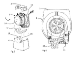
Fig. 5 is an exploded view of the machine ofFig. 1 ; -
Fig. 6 is a rear view of a part of the machine ofFig. 1 . - Referring now to
Figs. 1, 2 and5 , there is shown a preferred embodiment of a laundry treating machine 1 according to the present invention. - More specifically, the machine 1 is a laundry washing machine.
- It comprises an
oscillating assembly 2 which in turn comprises arotary drum 7 and atub 8 internally housing saiddrum 7. - Above the oscillating
assembly 2, and secured thereto, there is acounterweight 3 that partially embraces the tub and rests thereon, secured through one or more screws or bolts or welded to the tub, e.g. through a vibration welding process as described in patent applicationW02007/101781 . - The
counterweight 3 therefore can move integrally with the oscillatingassembly 2; in general, it must be pointed out right away that thecounterweight 3 is optional. - Under the oscillating
assembly 2 and in contact therewith there is anelastic layer 5; the oscillatingassembly 2 rests on theelastic layer 5; in the preferred embodiment shown herein, the oscillatingassembly 2 is fully supported by thelayer 5 and has no other supports. - The
elastic layer 5 rests on abase 4 laid on the ground, thus being wholly interposed between thetub 8 and thebase 4. - Connection means may then be provided for connecting the oscillating assembly to the elastic layer and/or the
elastic layer 5 to thebase 4; for example, such means may comprise glue, joints or the like. - The oscillating assembly 2 (and therefore also the counterweight 3) is held in position by retaining means which allow it to move relative to the
base 4. - In this embodiment, as shown in
Fig. 6 , the oscillatingassembly 2 further comprises theelectric motor 10 that drives thedrum 7, thewater drain pump 11 and, more in general, all those functional parts of the machine 1, including acontrol board 13 which may be secured directly to thetub 8. - Alternatively, as shown in
Fig. 5 , thecontrol board 13 may be applied to thedoor 14, in particular to thehandle 70 that opens thedoor 14, saidhandle 70 being advantageously raised with respect to the horizontal centre line of thedoor 14 to improve the ergonomics of the machine 1. - The functional components shown in
Fig. 6 are advantageously protected from shocks or damage by acover 80 applied onto theoscillating assembly 2, in particular onto the rear portion thereof (opposite to the door 14). - In the machine 1 of the example shown herein, in fact, the
tub 8 is not covered by any cabinet, and therefore remains visible to the user and is also used as a support for thecontrol board 13. - It should be noted in this regard that in this configuration the
door 14 that closes the access opening for thedrum 7, shown inFig. 5 , is hinged directly to thetub 8. - It must be pointed out that in principle the
elastic layer 5 may be adopted in washing machines of any kind, even those having a cabinet that covers the oscillating assembly, without however departing from the teachings of the present invention. - Nonetheless, the machine shown in the annexed drawings by way of non-limiting example represents an extremely advantageous setup with a view of obtaining laundry treating machines, in particular washing machines, which are economical and simple to manufacture.
- In fact, the machines so made can advantageously do without a covering cabinet, resulting in lower costs and simpler production and assembly processes; in addition, the use of the
elastic layer 5 as a substitute for the dampers provides a cost reduction without jeopardising the quiet and proper operation of the machine. - In the non-limiting example illustrated herein, the axis of rotation XX of the
drum 7 shown inFig. 3 is not horizontal, but slightly inclined, so as to facilitate the access to the drum; this position of the axis of rotation XX must not however be considered as limiting, in that it may alternatively be horizontal or vertical without any substantial variations. - Referring now to the
elastic layer 5, its position is clearly shown inFigs. 3 and 4 , whereas one possible embodiment thereof is visible inFig. 5 . - In substance, the
elastic layer 5 acts as a support for the oscillatingassembly 2 and, more in particular, for thetub 8, which is in direct contact therewith. - The support surface of the
tub 8 on thelayer 5 is therefore distributed and not localized (as is the case of prior-art support feet, the support surface of which may even be defined as punctual), thus improving the distribution of the various loads and weights, which in this case do not compel the manufacturer to provide thetub 8 with specific reinforcements in the form of ribs or the like because the contact surface between thetub 8 and thelayer 5 is relatively large and the forces involved can be distributed evenly. In addition to the above-mentioned beneficial effects, the distributed support surface provided by theelastic layer 5 also ensures further advantages. - In the first place, it is important to underline that vibrations that propagate also in planes other than the vertical one are effectively absorbed by the
elastic layer 5. - It should be noted that the
tub 8 has a substantially cylindrical outer shape and thebase 4 has a concave cylinder-shaped seat 15 having a diameter which is greater than the outer diameter of thetub 8. - Between the two there is thus room for housing the
elastic layer 5, which layer is for this purpose designed like an elastic carpet (or mattress) and is curved in a manner such as to follow both the outer profile of thetub 8 and that of theconcave seat 15 of thebase 4. - As can be seen in
Figs. 3 and 4 , theelastic layer 5 extends under the tub at the front (near the door 14) and at the sides thereof, along the directrices of thetub 8 and substantially for the entire length thereof, so as to appear substantially C-shaped when viewed from above, with afront portion 51 and twoside portions - The reason for such a shape of the
elastic layer 5 is primarily to be found in the fact that theelectric motor 10, thepump 11 and other functional units of the machine 1 are fastened to the lower central area of thetub 8, so that they remain suspended from thetub 8 without touching thebase 4, which for this purpose includes ahousing recess 16 that opens into theconcave seat 15 in a substantially central position relative to the vertical plane of symmetry of thedrum 7. - Of course, although in the annexed drawings the
elastic layer 5 is shown as one piece, it may alternatively be subdivided into a number of parts, even separate from one another, without however departing from the scope and teachings of the present invention. - As far as the material of the
elastic layer 5 is concerned, any elastic material may be used, whether natural or synthetic, which proves to be suited to absorbing the vibrations generated when the machine is in operation, while at the same time ensuring a firm support for the oscillating assembly. - More specifically, some particularly suitable materials are polymeric materials like rubbers based on closed-cell ethylene-propylene synthetic caoutchouc, also called closed-cell EPDM, or foam polypropylene, also known as PPE, or closed-cell foam rubbers, or closed-cell foam polystyrene.
- The internal friction of said materials of the
elastic layer 5 dissipates the stresses generated in the oscillatingassembly 2, in particular when the drum is operating at high speed, e.g. during the spin cycle. - The ideal thickness of the
layer 5 may vary between 30 mm and 50 mm, and is preferably 40 mm. - The carpet-like or mattress-like
elastic layer 5 may be manufactured, in general, by moulding it into either a curved or flat shape; in this latter case, the elastic layer will then be bent by the weight of the oscillatingassembly 2. - As can be seen in
Figs. 3 and 4 , theelastic layer 5, once it has been positioned between thetub 8 and thebase 4, arranges itself therebetween in a manner such as to support thetub 8 at the sides and front thereof. - More specifically, it can be noted in
Fig. 4 that, with respect to the axis of rotation of thedrum 7, bothside portions layer 5 are arranged at about 60° along the outer perimeter of thetub 8, thus supporting the latter firmly. - As regards the
base 4, it is typically made of hard plastic materials, and in the machine 1 illustrated and described herein it is the only fixed part of the machine 1: in fact, it is the only part resting directly on the ground, since all the other parts of the machine 1 (oscillatingassembly 2,counterweight 3,door 14,control board 13,motor 10,pump 11 and more in general anything being a functional part of the machine 1) rest on the ground through the interposedelastic layer 5. - Many changes may of course be made by those skilled in the art without however departing from the scope and teachings of the present invention.
- For example, the
layer 5 may in principle have different shapes or be made of different materials, or be applied to a traditional machine equipped with a cabinet. - The
elastic layer 5 may also be used in combination with normal dampers of a traditional machine, e.g. in order to reduce the operating noise, although this will reduce the cost advantages. - Also, the
base 4 may be have different shapes not partially embracing thetub 8, unlike the example shown in the annexed drawings. - Furthermore, the
base 4 may be made of elastic material or theelastic layer 5 may be advantageously shaped in a manner such that it also acts as a base, extending downwards to touch the ground; of course, in this case the man skilled in the art will have to employ different thicknesses and shapes for the elastic layer 5: for example, for this purpose the latter may have an annular or substantially toroidal shape on which theoscillating assembly 2 is laid; moreover, in this latter case the lower support portion is preferably flat, so as to ensure a firm support on the floor or on the ground. - Finally, aiming at simplifying the method of manufacturing the machine 1, it is conceivable that the
elastic layer 5 is co-moulded onto thetub 8 or onto the base 4 (if the latter is sufficiently rigid).
Claims (10)
- A laundry treating machine (1), in particular a laundry washing machine, of the type comprising at least one oscillating assembly (2) which comprises at least one rotary drum (7) housed in a tub (8),
characterised in that
said oscillating assembly (2) rests on an elastic layer (5). - Machine (1) according to claim 1, further comprising a base (4) which can be laid on the ground, and wherein said elastic layer (5) is interposed between said oscillating assembly (2) and said base (4).
- Machine (1) according to claim 1 or 2, wherein said oscillating assembly (2) is completely supported by the elastic layer (5).
- Machine (1) according to claim 1 or 2 or 3, wherein said elastic layer (5) is wholly interposed between said tub (8) and said base (4), so as to provide a distributed support surface for said tub (8).
- Machine (1) according to one or more of claims 1 to 4, wherein said machine (1) further comprises retaining means for holding said oscillating assembly (2) in position relative to said base (4), said retaining means being adapted to allow at least one relative movement of said oscillating assembly (2) with respect to said base (4).
- Machine (1) according to one or more of claims 1 to 4, wherein said elastic layer (5) is made of a polymeric material, in particular of rubbers based on closed-cell ethylene-propylene synthetic caoutchouc, or foam polypropylene (PPE), or closed-cell foam rubbers.
- Machine (1) according to one or more of claims 1 to 6, wherein said tub (8) has a substantially cylindrical outer shape and the base (4) has a concave cylinder-shaped seat (15) having a diameter which is greater than the outer diameter of said tub (8), the elastic layer (5) being interposed between the two and being curved in a manner such as to follow both the outer profile of the tub (8) and that of said concave seat (15) of the base (4).
- Machine (1) according to claim 7, wherein said elastic layer (5) extends at least under the tub at the front and sides thereof, along the directrices of said tub (8) and substantially for the entire length thereof.
- Machine (1) according to one or more of claims 1 to 8, wherein said tub (8) is accessible and visible from the outside, said machine (1) having no cabinet covering the tub (8), wherein a door (14) is hinged to said tub (8) for preventing access to the drum (7), and wherein said tub (8) supports at least one of a control board (13) for controlling the operation of said machine (1), an electric motor (10) for driving the drum (7), a water pump (11), or similar functional parts of the machine (1).
- Machine (1) according to claim 1, wherein said elastic layer (5) can be laid directly on the ground.
Applications Claiming Priority (1)
| Application Number | Priority Date | Filing Date | Title |
|---|---|---|---|
| IT000081A ITTO20100081A1 (en) | 2010-02-04 | 2010-02-04 | MACHINE FOR TREATMENT OF CLOTHS |
Publications (1)
| Publication Number | Publication Date |
|---|---|
| EP2354291A1 true EP2354291A1 (en) | 2011-08-10 |
Family
ID=42729176
Family Applications (1)
| Application Number | Title | Priority Date | Filing Date |
|---|---|---|---|
| EP11152867A Withdrawn EP2354291A1 (en) | 2010-02-04 | 2011-02-01 | Laundry treating machine |
Country Status (2)
| Country | Link |
|---|---|
| EP (1) | EP2354291A1 (en) |
| IT (1) | ITTO20100081A1 (en) |
Cited By (1)
| Publication number | Priority date | Publication date | Assignee | Title |
|---|---|---|---|---|
| CN104041977A (en) * | 2014-07-04 | 2014-09-17 | 湖州润源丝织有限公司 | Fabric expansion and storage structure |
Citations (5)
| Publication number | Priority date | Publication date | Assignee | Title |
|---|---|---|---|---|
| FR1380305A (en) * | 1964-01-24 | 1964-11-27 | Elastic connection device | |
| GB1107309A (en) * | 1964-10-22 | 1968-03-27 | Ges Fuer Technischen Fortschritt Mbh | Improvements in or relating to the resilient mounting of spinner units of washing and the like machines |
| US5934107A (en) * | 1997-02-18 | 1999-08-10 | Samsung Electronics Co., Ltd. | Clothes washing machine having an impact damper |
| EP1462562A1 (en) | 2003-03-28 | 2004-09-29 | Merloni Elettrodomestici S.p.A. | A laundry washing and /or drying machine, in particular of the front loading type, with lower housing |
| WO2007101781A1 (en) | 2006-03-07 | 2007-09-13 | BSH Bosch und Siemens Hausgeräte GmbH | Household appliance with a lye container |
-
2010
- 2010-02-04 IT IT000081A patent/ITTO20100081A1/en unknown
-
2011
- 2011-02-01 EP EP11152867A patent/EP2354291A1/en not_active Withdrawn
Patent Citations (5)
| Publication number | Priority date | Publication date | Assignee | Title |
|---|---|---|---|---|
| FR1380305A (en) * | 1964-01-24 | 1964-11-27 | Elastic connection device | |
| GB1107309A (en) * | 1964-10-22 | 1968-03-27 | Ges Fuer Technischen Fortschritt Mbh | Improvements in or relating to the resilient mounting of spinner units of washing and the like machines |
| US5934107A (en) * | 1997-02-18 | 1999-08-10 | Samsung Electronics Co., Ltd. | Clothes washing machine having an impact damper |
| EP1462562A1 (en) | 2003-03-28 | 2004-09-29 | Merloni Elettrodomestici S.p.A. | A laundry washing and /or drying machine, in particular of the front loading type, with lower housing |
| WO2007101781A1 (en) | 2006-03-07 | 2007-09-13 | BSH Bosch und Siemens Hausgeräte GmbH | Household appliance with a lye container |
Cited By (2)
| Publication number | Priority date | Publication date | Assignee | Title |
|---|---|---|---|---|
| CN104041977A (en) * | 2014-07-04 | 2014-09-17 | 湖州润源丝织有限公司 | Fabric expansion and storage structure |
| CN104041977B (en) * | 2014-07-04 | 2015-10-21 | 湖州润源丝织有限公司 | A kind of fabric expansion container structure |
Also Published As
| Publication number | Publication date |
|---|---|
| ITTO20100081A1 (en) | 2011-08-05 |
Similar Documents
| Publication | Publication Date | Title |
|---|---|---|
| US8234889B2 (en) | Laundry machine | |
| KR102482550B1 (en) | Cloth Treating Apparatus | |
| KR101596104B1 (en) | Assembly for washing machine using the frame for reducing vibration | |
| JP2010194024A (en) | Washing machine | |
| JP2010194023A (en) | Washing machine | |
| EP1950338A1 (en) | Household appliance column assembly | |
| CN107012656B (en) | Movable drum washing machine with clothes taking and putting opening | |
| KR102818389B1 (en) | Laundry treating apparatus | |
| CN215628841U (en) | Bottom plate assembly of clothes treatment device and clothes treatment device | |
| US12312732B2 (en) | Laundry treating apparatus | |
| CN107354669B (en) | Clothes treating device | |
| JP2911234B2 (en) | Drum type washing machine | |
| KR101770815B1 (en) | Leg for washing machine | |
| WO2008017387A1 (en) | Floor stabilizing foot for an appliance | |
| CN107012646B (en) | Movable drum washing machine with clothes taking and putting opening | |
| CN107012643B (en) | Movable drum washing machine with clothes taking and putting opening | |
| ITTO20100081A1 (en) | MACHINE FOR TREATMENT OF CLOTHS | |
| CN211340104U (en) | Washing machine with shock-absorbing function | |
| KR101453275B1 (en) | Wall mounted drum type washing apparatus | |
| KR101461393B1 (en) | Wall mounted drum type washing machine | |
| KR101282032B1 (en) | Drum type washing machine | |
| CN107012657B (en) | Movable drum washing machine with clothes taking and putting opening | |
| KR20080042603A (en) | washer | |
| JP2006204497A (en) | Washing machine | |
| KR101217117B1 (en) | Drum Type Washing Machine |
Legal Events
| Date | Code | Title | Description |
|---|---|---|---|
| PUAI | Public reference made under article 153(3) epc to a published international application that has entered the european phase |
Free format text: ORIGINAL CODE: 0009012 |
|
| AK | Designated contracting states |
Kind code of ref document: A1 Designated state(s): AL AT BE BG CH CY CZ DE DK EE ES FI FR GB GR HR HU IE IS IT LI LT LU LV MC MK MT NL NO PL PT RO RS SE SI SK SM TR |
|
| AX | Request for extension of the european patent |
Extension state: BA ME |
|
| 17P | Request for examination filed |
Effective date: 20120203 |
|
| 17Q | First examination report despatched |
Effective date: 20120315 |
|
| STAA | Information on the status of an ep patent application or granted ep patent |
Free format text: STATUS: THE APPLICATION IS DEEMED TO BE WITHDRAWN |
|
| 18D | Application deemed to be withdrawn |
Effective date: 20130903 |