EP2354286A1 - Yarn nipping device for weft knitting machine - Google Patents
Yarn nipping device for weft knitting machine Download PDFInfo
- Publication number
- EP2354286A1 EP2354286A1 EP09818973A EP09818973A EP2354286A1 EP 2354286 A1 EP2354286 A1 EP 2354286A1 EP 09818973 A EP09818973 A EP 09818973A EP 09818973 A EP09818973 A EP 09818973A EP 2354286 A1 EP2354286 A1 EP 2354286A1
- Authority
- EP
- European Patent Office
- Prior art keywords
- nip
- knitting yarn
- knitting
- yarn
- gripping
- Prior art date
- Legal status (The legal status is an assumption and is not a legal conclusion. Google has not performed a legal analysis and makes no representation as to the accuracy of the status listed.)
- Granted
Links
Images


Classifications
-
- D—TEXTILES; PAPER
- D04—BRAIDING; LACE-MAKING; KNITTING; TRIMMINGS; NON-WOVEN FABRICS
- D04B—KNITTING
- D04B15/00—Details of, or auxiliary devices incorporated in, weft knitting machines, restricted to machines of this kind
- D04B15/38—Devices for supplying, feeding, or guiding threads to needles
- D04B15/54—Thread guides
- D04B15/56—Thread guides for flat-bed knitting machines
- D04B15/565—Associated thread-clamping or thread-severing devices
Definitions
- the present invention relates to a knitting yarn gripping device, which is installed on the side of a needle bed and holds a knitting yarn, for a flatbed knitting machine.
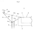
- a flatbed knitting machine 1 as simply shown in Fig. 7 , at least one pair of needle beds 2 have been installed opposed to each other in the front and in the rear with a needle bed gap 3 between them.
- a head end side of a knitting needle whose illustration is omitted, advances and retreats, and continuously knits sweaters and other products as a tubular fabric 4 while forming the fabrics into a final shape, and is able to manufacture a sweater and other product without sewing.
- knitting yarn 6 is fed from a yarn feeder port 5 moving above the needle bed gap 3 to knitting needles.
- the yarn feeder port 5 goes out to the outer side of the needle bed 2.
- the knitting yarn 6 extends aslant from the final loop knitted in the knitting fabric 4 to the yarn feeder port 5.
- the fabric 4 is discharged from knitting needles of the needle bed 2 to below the needle bed gap 3 and the knitting needles must be emptied. Discharging the fabric 4 with the knitting yarn 6 connected from the final loop to the yarn feeder port 5 links the knitting yarn 6 to a start loop of a knit fabric 4 to be knitted next, and the knitting yarn 6 continues between successively manufactured fabrics 4. When the knitting yarn 6 continues, discharge of fabric 4 is unable to be smoothly performed, requiring operation for cutting out the continuing knitting yarn 6 after discharging.
- the cutting device 7 is installed to cut off the knitting yarn 6 extending from the fabric 4 to the yarn feeder port 5.
- the fabric 4 is able to be smoothly discharged, and operation for cutting out the knitting yarn 6 between fabric 4 after discharging is no longer required.
- the knitting yarn 6 is only cut, the head end of the knitting yarn 6 remaining on the yarn feeder port 5 side so as to go into floating state.
- the knitting yarn 6 whose head end is floating to move together with the yarn feeder port 5 and is unable to be used for knitting fabric 4 by feeding it to a knitting yarn that advances to the needle bed gap 3.
- a gripping device 8 is installed to the side of an area in which a knitting needle advances and retreats from front and rear needle beds 2 at the needle bed gap 3, and even when the knitting yarn 6 extending to the yarn feeder port 5 is cut by the cutting device 7, the gripping device 8 is able to hold the end of the knitting yarn 6 (for example, see Patent Citation 1).
- the yarn feeder port 5 moves above the needle bed gap 3 and is able to feed the knitting yarn 6 to a knitting needle that advances and retreats to and from the needle bed gap 3.
- Holding of the knitting yarn 6 by the gripping device 8 is performed by gripping mechanisms 9a, 9b which are installed to the top end and are able to be opened and closed.
- the gripping mechanism 9a which is in a closed state during fall, become the gripping mechanism 9b in the open state and rises so that the gripping mechanism 9b is able to capture the knitting yarn 6 extending aslant from the final loop of the fabric 4 to the yarn feeder port 5 as shown by a chain double-dashed line.
- the gripping mechanism 9b begins falling after rising, the gripping mechanism 9b becomes the gripping mechanism 9a in the closed state, and after falling, knitting yarn 6a between the gripping mechanism 9a in the closed state and the fabric 4 is cut by the cutting device 7.
- the gripping mechanism 9a in the closed state grips the head end of knitting yarn 6b which is pulled out from the yarn feeder port 5 and serves as a yarn end and is able to keep holding the yarn.
- the gripping mechanism 9a in the closed state falls with knitting yarn 6 gripped, and the knitting yarn 6a between knit fabric 4 is therefore stretched from the state of the chain double-dashed line to the state of the solid line.
- the knitting yarn 6b from the gripping mechanism 9a in the closed state to the yarn feeder port 5 is lengthened from the state of the chain double-dashed line to the state of the solid line, the knitting yarn 6 is replenished from the yarn feeder port 5. Because no knitting yarn 6 is replenished from the yarn feeder port 5 to the knitting yarn 6a, tension of the knitting yarn 6a increases.
- the stitch of the final loop of the fabric 4 may become dense or yarn breakage may occur when the next course is being knitted.
- the yarn may break when the yarn is gripped by the gripping device 8 during fall.
- the present invention provides a knitting yarn gripping device for a flatbed knitting machine, provided with a gripping mechanism equipped to an upper end thereof, so that the gripping mechanism is capable of capturing a knitting yarn in an opening state during rise from downward of a needle bed gap to upward thereof and holds to capture the knitting yarn by closing during fall after rising, while the knitting yarn is crossing from a fabric under knitting in needle beds to a yarn feeder port, and a rise and fall mechanism equipped below the gripping mechanism, comprising:
- the lock member has a support part and two arms extended from and supported by the support part in a state to be capable of swinging displacement, performs said locking by one arm, and said unlock mechanism is mounted to the rise and fall mechanism so as to work on the other arm of the lock member.
- said gripping mechanism has three plate-form nip claws lapped over each other so that base end sides displace by swing around a shared swinging shaft, two outside nip claws are linked each other to displace by swing in the same direction, and an inside nip claw displaces by swing in the opposite direction to the two outside nip claws, and a space between head end sides of the outside nip claws and a head end side of the inside nip claw opens and closes, and concerning said lock member, said support part is supported by the inside nip claw in a manner capable of swinging displacement, and said one arm works on one of the two outside nip claws to hold on the gripping mechanism to said stage of capturing before gripping knitting yarn.
- rods for forming a link mechanism and for opening and closing it, are connected to said outside nip claws and said inside nip claw, and said support part of said lock member is supported in a manner capable of swinging displacement by linking parts of the rods to the inside nip claw.
- the knitting yarn gripping device for a flatbed knitting machine comprises a lock member and an unlocking mechanism. Since the lock member locks the gripping mechanism that falls after rising in a state on the way of closing and holding on the gripping mechanism to a stage of capturing before gripping knitting yarn, it is possible to replenish knitting yarn from a yarn feeder port during falling to prevent knitting yarn tension from being excessively increased and to prevent occurrence of dense stitches or yarn breakage.
- the unlocking mechanism works on the lock member when the gripping mechanism continues falling after locking, unlocks to allow the gripping mechanism to grip knitting yarn, and thereby, enables the gripping mechanism to securely hold the head end of the knitting yarn which becomes a yarn end.
- a lock member that works on between opening and closing nip claws is installed so as to allow the lock member to easily perform locking on the way of closing of nip claws.
- the lock member is able to be incorporated by the use of a link mechanism that opens and closes nip claws, and therefore, an increase of the number of components is able to be suppressed to a minimum.
- Fig. 1 simply shows a structure of a knitting yarn gripping device 10 for a flatbed knitting machine as one embodiment of the present invention.
- the knitting yarn gripping device 10 for a flatbed knitting machine is basically equipped with a structure similar to that of a knitting yarn gripping device disclosed in Patent Citation 1, has a gripping mechanism 10a on an upper end, and has a rise and fall mechanism 10b below the gripping mechanism 10a.
- the figure shows a lock state in a capturing stage of the knitting yarn gripping device 10 of a flatbed knitting machine as a front structure 10A as viewed from the outer side of a flatbed knitting machine, and also shows a rear structure 10B in part.
- the gripping mechanism 10a is equipped with three nip claws 11, 12, 13, and the two outside nip claws 11, 13 operate in linkage and open and close the head ends with the inside nip claw 12.
- the three nip claws 11, 12, 13 displace by swing around a shared nip shaft 14, and open and close the head end sides.
- To the nip claw 12 and the nip claws 11, 13, top ends of small rods 15, 16 are connected, respectively. Bottom ends of the small rods 15, 16 are connected by a rod shaft 17.
- Nip claws 11, 13, nip claw 12, and small rods 15, 16 form a link mechanism that enables a clearance between head ends to open and close in accordance with the size of the clearance between the nip shaft 14 and the rod shaft 17.
- the nip shaft 14 is fixed to the vicinity of the top end of a fixing plate 18.
- the fixing plate 18 has a substantially plate form that extends vertically, and in the midway, an elongated hole 18a is formed.
- a rack 18b is formed on one side of the fixing plate 18.
- a hook 19 is mounted in a state capable of displacing by swing around a hook shaft 20.
- the hook 19 has a substantially L-letter shape, and a head end of a long side of the hook 19 is supported capable of swinging displacement.
- a long side of the hook 19 is pressed by a push spring 21 from the side, and is energized to protrude to the head end side of a short side.
- the rod shaft 17 is fixed to the vicinity of the top end of an operating plate 22.
- the operating plate 22 is connected to the fixing plate 18 via a pull spring 23.
- the pull spring 23 is housed in a space formed by an elongated hole 22a formed in the midst of the operating plate 22 and an elongated hole 18a of the fixing plate 18.
- the operating plate 22 is used lying on top of the fixing plate 18, and a notched part 22b is formed on a side in which a cam recess 18c is formed in the fixing plate 18.
- the cam recess 18c and the notched part 22b are installed in order to operate a swing claw 26 that can displace by swing around a swing shaft 25.
- the fixing plate 18 has the side rack 18b meshed with a pinion 28.
- the fixing plate 18 and the pinion 28 form an essential part of the rise and fall mechanism 10b.
- a rotate shaft 29 of the pinion 28 rotates driven by a motor or the like, the fixing plate 18 can be displaced to rise and fall.
- the pull spring 23 energizes the fixing plate 18 to bring the operating plate 22 closer, and therefore, the gripping mechanism 10a is energized in the closing direction via a link mechanism.
- the rise and fall displacement of the fixing plate 18 and the operating plate 22 is performed to slide against a supporting block 40.
- the supporting block 40 is mounted to a side of a needle bed in a flatbed knitting machine.
- the supporting block 40 also support the swing shaft 25 of the swing claw 26 and the rotate shaft 29, and are included in the rise and fall mechanism 10b as the essential part.
- a contact part 40a is installed to the lower part of the supporting block 40, and when the head end of the hook 19 comes in contact with the contact part 40a, the locked state between the fixing plate 18 and the operating plate 22 by the hook 19 is unlocked.
- the knitting yarn gripping device 10 for a flatbed knitting machine allows the gripping mechanism 10a to lock a link mechanism in the state on the way of closing, and includes a lock lever 30 that holds on the gripping mechanism 10a to the stage of capturing before gripping the knitting yarn.
- the lock lever 30 has a substantially L-letter shape, and the head end of the short arm 30a comes in contact with a lock part 13a installed to the nip claw 13 and latches.
- the lock lever 30 is energized by a wire spring 31 in the counterclockwise direction in the front structure 10A.
- the contact portion of the head end of the short arm 30a and the lock part 13a is kept latched by the wire spring 31, which energizes counterclockwise.
- the contact condition is unlocked so that the lock lever 30 displaces by swing to the clockwise direction when a force heading to the upper part of the figure is applied to the vicinity of the head end of the long arm 30b of the lock lever 30.
- an intermediate portion between the short arm 30a and the long arm 30b serves as a support part, is supported capable of swinging displacement by the connecting pin 32 that connects the top end of the small rod 15 to the nip claw 12.
- the top end of the small rod 16 is mutually connected by the connecting pin 33 while being sandwiched between two nip claws 11, 13. Since other nip claws 11, 12 also form a link mechanism with small rods 15, 16, connecting pins 32, 33, and rod shaft 17, locking the space between the nip claw 12 and the nip claw 13 by the short arm 30a can lock the whole link mechanism and prevent the gripping mechanism 10a from being completely closed.
- the lock lever 30 functions as a lock member that locks the link mechanism, though its shape could be changed in cases where locations to be disposed might be changed.
- a capturing space 10c is formed and knitting yarn is able to be pulled down under the non-gripped state even if the knitting yarn is captured. Since the gripping mechanism 10a does not grip knitting yarn, even on the way of pulling down knitting yarn, knitting yarn is allowed to pass from the yarn feeder port to the capturing space 10c so as to replenish knitting yarn to the section from the gripping mechanism 10 to the fabric. Since excessive tension is not applied across the gripping mechanism 10a and the fabric, even after the gripping mechanism 10a closes and grips knitting yarn after the gripping mechanism falls, it is able to prevent dense stitches from occurring or yarn from breaking.
- Fig. 2 shows a state in which the claw part 26a of the swing claw 26 is fitted into the notched part 22b of the operating plate 22, and the nip claws 11, 13 and the nip claw 12 are opened and locked. Even when the fixing plate 18 rises by rotations of the pinion 28, the operating plate 22 stops rising, and as shown in the front structure 10A, the left side structure 10C and the planar structure 10D, the gripping mechanism 10a opens the spaces between the nip claws 11, 13 and the nip claw 12.
- Fig. 3 shows a state in which a knitting yarn might be captured and then, the fixing plate 18 is allowed to fall as shown in Fig. 1 , the head end vicinity of the long arm 30b of the lock lever 30 is brought into contact with the contact part 40b provided at the upper part of the supporting block 40, and the lock to the gripping mechanism 10a is unlocked.
- the head end of the short arm 30a of the lock lever 30 disengages from the contact state of the nip claw 13 against the lock part 13a, and therefore, the gripping mechanism 10a completely closes by being energized with the pull spring 23.
- the knitting yarn might be captured in the capturing space 10c formed between the nip claws 11, 13 and the nip claw 12 under the lock state of Fig 1 is held by grip between the nip claws 11, 13 and the nip claw 12. Since the yarn end is securely held by the grip of the gripping mechanism 10a when knitting begins, the following fabrics are able to be knitted without any problem.
- Fig. 4 and Fig. 5 show structures of essential components that configure the knitting yarn gripping device 10 for a flatbed knitting machine.
- A is added to the referential mark of each component of the front structure, C to each component of the left side structure, and D to each component of the plane structure, respectively.
- Fig. 4 shows components of the gripping mechanism 10a and the supporting block 40.
- a lock part 13a is formed.
- the lock lever 30 has a substantially L-letter shape in the front structure 30A and the intermediate between the short arm 30a and the long arm 30b serves as a support part 30c for swinging displacement.
- a stepped part 30d that houses the upper side part of the wire spring 31 is formed to the long arm 30b.
- the lower side part 31b of the wire spring 31 is supported by the vicinity of the top end of the operating plate 22.
- the lock lever 30 is able to be assembled as part of a link mechanism that opens and closes the nip claws 11, 12, 13 composed with the small rods 15, 16, the nip shaft 14, the connecting pins 32, 33 and the like.
- the long arm 30b of the lock lever 30 unlocks the lock when the long arm 30b comes in contact with the contact part 40b formed on the upper part of the supporting block 40. Consequently, the contact part 40b of the supporting block 40 is functioning as an unlocking mechanism that unlocks the lock of the gripping mechanism 10a.
- Components that perform functions as the unlocking mechanism may be able to be installed separately from the supporting block 40.
- Guide grooves 40c, 40d that house the fixing plate 18 and the operating plate 22 are formed on the front and the back of the supporting block 40, and are able to support two sets of the knitting yarn gripping device 10 for a flatbed knitting machine.
- Fig. 5 shows the fixing plate 18, the hook 19, the operating plate 22, and the swing claw 26 as components of the rise and fall mechanism 10b.
- the elongated opening hole 18a, the rack 18b, and the cam recess 18c are formed to the fixing plate 18.
- a fixing hole 18d for the nip shaft 14 an elongated opening hole 18e that serves as a back clearance for the head of the rod shaft 17, a fixing hole 18f for a top end support pin to the pull spring 23, a fixing hole 18g for the hook shaft 20 or the like are formed.
- the hook 19 has an L-letter shape, and the intermediate part 19a between the long side and the short side comes into contact with the lower part of the operating plate 22 and locks the space between the fixing plate 18 and the operating plate 22.
- An insertion hole 19b for the hook shaft 20 is formed at the head end on the side of the long side of the hook 19.
- the elongated opening hole 22a and the notched part 22b are formed on the operating plate 22.
- a fixing hole 22c of the rod shaft 17, fixing hole 22d for the lower end support pin of the pull spring 23, and a contact part 22e to which the intermediate part 19a of the hook 19 comes into contact in the locked state are formed on the operating plate 22.
- a spring support part 22f that supports a lower side part 31b of the wire spring 31 is formed in the vicinity of the top end of the operating plate 22.
- the swing claw 26 has a substantially L-letter shape, and the claw part 26a at the head end fits into the notched part 22b of the operating plate 22, and at the same time, the insertion hole 26b through which the swing shaft 25 inserts is installed. In addition, in the vicinity of the insertion hole 26b, at a position of the claw part 26a side, the roller 27 is installed.
- Fig. 6 is an exploded perspective view showing a structure of one side of one flatbed knitting machine equipped with two sets of the knitting yarn gripping device 10 for a flatbed knitting machine.
- a driving unit 50 incorporates a motor that rotary drives two rotary shafts 29, and are supported opposite to each other on the side surfaces of the needle beds by the frames of the flatbed knitting machine.
- the two sets of the knitting yarn gripping device 10 for a flatbed knitting machine are housed in guide grooves 40c, 40d of the supporting block 40 disposed between the driving unit 50 and the side surface of the needle bed.
- a cutting device support block 51 is mounted to the position close to the side surface of the needle bed and houses a cutting device with functions similar to those of the cutting device 7 shown simplified in Fig. 7 is housed.
- the driving force of the cutting device is taken out from the driving unit 50 and is transmitted.
- Cover plates 52, 53 are disposed between the knitting yarn gripping device 10 for a flatbed knitting machine and a cutting device support block 51.
- a plate spring 54 is installed on the side of the supporting block 40 which is located in the longitudinal direction as a flatbed knitting machine. The plate spring 54 presses the swing claw 26 from outside and energizes the claw part 26a in the state of Fig. 2 in such a manner as to press against the notched part 22b side of the operating plate 22.
- the lock lever 30 is disposed on the same side of the nip claw 13 with respect to the nip claw 12, and therefore, the structure for locking in the capturing stage is able to be made compactly.
- the knitting yarn gripping device 10 for a flatbed knitting machine as described above can open and close the gripping mechanism 10a by vertical motion of the rise and fall mechanism 10b and keeps the knitting yarn in the lock state on the way of closing to the stage of capturing the knitting yarn in the capturing space 10c. Even if the captured knitting yarn made to fall, the knitting yarn is replenished between the gripping mechanism 10a and the fabric through the capturing space 10c from the yarn feeder port, and therefore, excessive tension is not applied to the knitting yarn, and dense stitches and yarn breakage are able to be avoided. As shown in Fig. 3 , when upward force is applied to the vicinity of the head end of the long arm 30b of the lock lever 30, the locked state is unlocked, the gripping mechanism 10a closes, and the captured knitting yarn is able to be gripped.
Landscapes
- Engineering & Computer Science (AREA)
- Textile Engineering (AREA)
- Knitting Machines (AREA)
- Braiding, Manufacturing Of Bobbin-Net Or Lace, And Manufacturing Of Nets By Knotting (AREA)
Abstract
Description
- The present invention relates to a knitting yarn gripping device, which is installed on the side of a needle bed and holds a knitting yarn, for a flatbed knitting machine.
- Conventionally, in a
flatbed knitting machine 1 as simply shown inFig. 7 , at least one pair ofneedle beds 2 have been installed opposed to each other in the front and in the rear with aneedle bed gap 3 between them. From the front and rear needle beds 2 to theneedle bed gap 3, a head end side of a knitting needle, whose illustration is omitted, advances and retreats, and continuously knits sweaters and other products as atubular fabric 4 while forming the fabrics into a final shape, and is able to manufacture a sweater and other product without sewing. When this kind offabric 4 is continuously knitted, knittingyarn 6 is fed from ayarn feeder port 5 moving above theneedle bed gap 3 to knitting needles. When it is finished to use of knittingyarn 6 for knittingfabrics 4, theyarn feeder port 5 goes out to the outer side of theneedle bed 2. Theknitting yarn 6 extends aslant from the final loop knitted in the knittingfabric 4 to theyarn feeder port 5. - For the next knitting, the
fabric 4 is discharged from knitting needles of theneedle bed 2 to below theneedle bed gap 3 and the knitting needles must be emptied. Discharging thefabric 4 with theknitting yarn 6 connected from the final loop to theyarn feeder port 5 links theknitting yarn 6 to a start loop of aknit fabric 4 to be knitted next, and theknitting yarn 6 continues between successively manufacturedfabrics 4. When theknitting yarn 6 continues, discharge offabric 4 is unable to be smoothly performed, requiring operation for cutting out the continuingknitting yarn 6 after discharging. - The
cutting device 7 is installed to cut off theknitting yarn 6 extending from thefabric 4 to theyarn feeder port 5. When theknitting yarn 6 is cut, thefabric 4 is able to be smoothly discharged, and operation for cutting out theknitting yarn 6 betweenfabric 4 after discharging is no longer required. However, if theknitting yarn 6 is only cut, the head end of theknitting yarn 6 remaining on theyarn feeder port 5 side so as to go into floating state. Even when theyarn feeder port 5 moves above theneedle bed 2 when thenext fabric 4 is knitted, theknitting yarn 6 whose head end is floating to move together with theyarn feeder port 5 and is unable to be used for knittingfabric 4 by feeding it to a knitting yarn that advances to theneedle bed gap 3. - A
gripping device 8 is installed to the side of an area in which a knitting needle advances and retreats from front andrear needle beds 2 at theneedle bed gap 3, and even when theknitting yarn 6 extending to theyarn feeder port 5 is cut by thecutting device 7, thegripping device 8 is able to hold the end of the knitting yarn 6 (for example, see Patent Citation 1). When thenext fabric 4 is knitted, theyarn feeder port 5 moves above theneedle bed gap 3 and is able to feed theknitting yarn 6 to a knitting needle that advances and retreats to and from theneedle bed gap 3. Holding of theknitting yarn 6 by thegripping device 8 is performed by gripping mechanisms 9a, 9b which are installed to the top end and are able to be opened and closed. The gripping mechanism 9a, which is in a closed state during fall, become the gripping mechanism 9b in the open state and rises so that the gripping mechanism 9b is able to capture theknitting yarn 6 extending aslant from the final loop of thefabric 4 to theyarn feeder port 5 as shown by a chain double-dashed line. When the gripping mechanism 9b begins falling after rising, the gripping mechanism 9b becomes the gripping mechanism 9a in the closed state, and after falling, knitting yarn 6a between the gripping mechanism 9a in the closed state and thefabric 4 is cut by thecutting device 7. In thegripping device 8 after descending, the gripping mechanism 9a in the closed state grips the head end of knitting yarn 6b which is pulled out from theyarn feeder port 5 and serves as a yarn end and is able to keep holding the yarn. - Patent Citation 1: Japanese Examined Patent Publication No.
4-74463 - In the
gripping device 8 disclosed inPatent Citation 1, as shown inFig. 7 , the gripping mechanism 9a in the closed state falls withknitting yarn 6 gripped, and the knitting yarn 6a betweenknit fabric 4 is therefore stretched from the state of the chain double-dashed line to the state of the solid line. Even if the knitting yarn 6b from the gripping mechanism 9a in the closed state to theyarn feeder port 5 is lengthened from the state of the chain double-dashed line to the state of the solid line, theknitting yarn 6 is replenished from theyarn feeder port 5. Because noknitting yarn 6 is replenished from theyarn feeder port 5 to the knitting yarn 6a, tension of the knitting yarn 6a increases. When the tension of the knitting yarn 6a excessively increases, the stitch of the final loop of thefabric 4 may become dense or yarn breakage may occur when the next course is being knitted. Depending on the types ofknitting yarn 6, the yarn may break when the yarn is gripped by thegripping device 8 during fall. - Even in the event that yarn breakage does not occur but stitches become dense only, the dense stitches come to the surface to cause quality reduction when non-sewing products are manufactured as a
knit fabric 4. Incidentally, ifknit fabric 4 is a part for a commercial product by sewing, the portion of dense stitches is generally used for seam allowance and does not come to the product surface. - It is an object of the present invention to provide a knitting yarn gripping device that does not cause dense stitches or yarn breakage even if the knitting yarn is gripped, for a flatbed knitting machine.
- The present invention provides a knitting yarn gripping device for a flatbed knitting machine, provided with a gripping mechanism equipped to an upper end thereof, so that the gripping mechanism is capable of capturing a knitting yarn in an opening state during rise from downward of a needle bed gap to upward thereof and holds to capture the knitting yarn by closing during fall after rising, while the knitting yarn is crossing from a fabric under knitting in needle beds to a yarn feeder port, and a rise and fall mechanism equipped below the gripping mechanism, comprising:
- a lock member for locking the gripping mechanism that falls after rising in a state on a way of closing and holding on the gripping mechanism to a stage of capturing before gripping the knitting yarn; and
- an unlock mechanism for working on the lock member to unlock it so as to grip the knitting yarn, if the gripping mechanism continues to fall after being locked.
- In addition, in the present invention, the lock member has a support part and two arms extended from and supported by the support part in a state to be capable of swinging displacement, performs said locking by one arm, and
said unlock mechanism is mounted to the rise and fall mechanism so as to work on the other arm of the lock member. - In addition, in the present invention, said gripping mechanism has three plate-form nip claws lapped over each other so that base end sides displace by swing around a shared swinging shaft,
two outside nip claws are linked each other to displace by swing in the same direction, and an inside nip claw displaces by swing in the opposite direction to the two outside nip claws, and a space between head end sides of the outside nip claws and a head end side of the inside nip claw opens and closes, and
concerning said lock member, said support part is supported by the inside nip claw in a manner capable of swinging displacement, and said one arm works on one of the two outside nip claws to hold on the gripping mechanism to said stage of capturing before gripping knitting yarn. - In addition, in the present invention, rods, for forming a link mechanism and for opening and closing it, are connected to said outside nip claws and said inside nip claw, and
said support part of said lock member is supported in a manner capable of swinging displacement by linking parts of the rods to the inside nip claw. - According to the present invention, the knitting yarn gripping device for a flatbed knitting machine comprises a lock member and an unlocking mechanism. Since the lock member locks the gripping mechanism that falls after rising in a state on the way of closing and holding on the gripping mechanism to a stage of capturing before gripping knitting yarn, it is possible to replenish knitting yarn from a yarn feeder port during falling to prevent knitting yarn tension from being excessively increased and to prevent occurrence of dense stitches or yarn breakage. The unlocking mechanism works on the lock member when the gripping mechanism continues falling after locking, unlocks to allow the gripping mechanism to grip knitting yarn, and thereby, enables the gripping mechanism to securely hold the head end of the knitting yarn which becomes a yarn end.
- Furthermore, according to the present invention, by a simple structure of using a lock member which has two arms extended from a support part that can displace by swing, locking and unlocking are able to be performed when rising and falling are performed by a rise and fall mechanism.
- Furthermore, according to the present invention, a lock member that works on between opening and closing nip claws is installed so as to allow the lock member to easily perform locking on the way of closing of nip claws.
- Furthermore, according to the present invention, the lock member is able to be incorporated by the use of a link mechanism that opens and closes nip claws, and therefore, an increase of the number of components is able to be suppressed to a minimum.
-
- [
Fig. 1] Fig. 1 is a front view and a partial back view showing schematic structure of a knittingyarn gripping device 10 for a flatbed knitting machine as one embodiment of the present invention. - [
Fig. 2] Fig. 2 is a front view, a left side view, and a plan view showing a state in which a claw part 26a of aswing claw 26 is fitted into a notched part 22b of anoperating plate 22 in the knittingyarn gripping device 10 for a flatbed knitting machine ofFig. 1 . - [
Fig. 3] Fig. 3 is a front view and a partial back view showing a state in which a gripping mechanism 10a is unlocked in a knittingyarn gripping device 10 for a flatbed knitting machine ofFig. 1 . - [
Fig. 4] Fig. 4 shows front views, left side views, and plan views about structures of components of the gripping mechanism 10a and a supportingblock 40 in the knittingyarn gripping device 10 for a flatbed knitting machine ofFig. 1 . - [
Fig. 5] Fig. 5 shows front views and left side views about structures of afixing plate 18, ahook 19, anoperating plate 22, and aswing claw 26 as components of a rise and fall mechanism 10b in the knittingyarn gripping device 10 for a flatbed knitting machine ofFig. 1 . - [
Fig. 6] Fig. 6 is an exploded perspective view showing a structure of a side part of a flatbed knitting machine equipped with the knittingyarn gripping device 10 for a flatbed knitting machine ofFig. 1 . - [
Fig. 7] Fig. 7 is a partial front view simply showing a structure of aflatbed knitting machine 1 equipped with aconventional gripping device 8. -
- 10
- Knitting yarn gripping device for flatbed knitting machine
- 10a
- Gripping mechanism
- 10b
- Rise and fall mechanism
- 10c
- Capturing space
- 11, 12, 13
- Nip claw
- 13a
- Locking part
- 14
- Nip shaft
- 15, 16
- Small rod
- 17
- Rod shaft
- 18
- Fixing plate
- 19
- Hook
- 22
- Operating plate
- 23
- Pull spring
- 26
- Swing claw
- 28
- Pinion
- 30
- Lock lever
- 40
- Supporting block
-
Fig. 1 simply shows a structure of a knittingyarn gripping device 10 for a flatbed knitting machine as one embodiment of the present invention. The knittingyarn gripping device 10 for a flatbed knitting machine is basically equipped with a structure similar to that of a knitting yarn gripping device disclosed inPatent Citation 1, has a gripping mechanism 10a on an upper end, and has a rise and fall mechanism 10b below the gripping mechanism 10a. The figure shows a lock state in a capturing stage of the knittingyarn gripping device 10 of a flatbed knitting machine as afront structure 10A as viewed from the outer side of a flatbed knitting machine, and also shows arear structure 10B in part. - The gripping mechanism 10a is equipped with three nip
claws claws claw 12. The three nipclaws nip shaft 14, and open and close the head end sides. To the nipclaw 12 and thenip claws small rods small rods rod shaft 17. Nipclaws claw 12, andsmall rods nip shaft 14 and therod shaft 17. - The
nip shaft 14 is fixed to the vicinity of the top end of a fixingplate 18. The fixingplate 18 has a substantially plate form that extends vertically, and in the midway, an elongated hole 18a is formed. A rack 18b is formed on one side of the fixingplate 18. On the other side of the fixingplate 18, a cam recess 18c is formed. In the vicinity of the bottom end of the fixingplate 18, ahook 19 is mounted in a state capable of displacing by swing around ahook shaft 20. Thehook 19 has a substantially L-letter shape, and a head end of a long side of thehook 19 is supported capable of swinging displacement. A long side of thehook 19 is pressed by apush spring 21 from the side, and is energized to protrude to the head end side of a short side. - The
rod shaft 17 is fixed to the vicinity of the top end of an operatingplate 22. The operatingplate 22 is connected to the fixingplate 18 via apull spring 23. Thepull spring 23 is housed in a space formed by an elongated hole 22a formed in the midst of the operatingplate 22 and an elongated hole 18a of the fixingplate 18. The operatingplate 22 is used lying on top of the fixingplate 18, and a notched part 22b is formed on a side in which a cam recess 18c is formed in the fixingplate 18. The cam recess 18c and the notched part 22b are installed in order to operate aswing claw 26 that can displace by swing around aswing shaft 25. When aroller 27 mounted to theswing claw 26 is guided by the cam recess 18c and the claw part 26a of the head end of theswing claw 26 fits into the notched part 22b, the operatingplate 22 is locked. Lock between the fixingplate 18 and the operatingplate 22 is also performed by thehook 19. - The fixing
plate 18 has the side rack 18b meshed with apinion 28. The fixingplate 18 and thepinion 28 form an essential part of the rise and fall mechanism 10b. When a rotateshaft 29 of thepinion 28 rotates driven by a motor or the like, the fixingplate 18 can be displaced to rise and fall. Thepull spring 23 energizes the fixingplate 18 to bring theoperating plate 22 closer, and therefore, the gripping mechanism 10a is energized in the closing direction via a link mechanism. The rise and fall displacement of the fixingplate 18 and the operatingplate 22 is performed to slide against a supportingblock 40. The supportingblock 40 is mounted to a side of a needle bed in a flatbed knitting machine. The supportingblock 40 also support theswing shaft 25 of theswing claw 26 and the rotateshaft 29, and are included in the rise and fall mechanism 10b as the essential part. A contact part 40a is installed to the lower part of the supportingblock 40, and when the head end of thehook 19 comes in contact with the contact part 40a, the locked state between the fixingplate 18 and the operatingplate 22 by thehook 19 is unlocked. - The knitting
yarn gripping device 10 for a flatbed knitting machine allows the gripping mechanism 10a to lock a link mechanism in the state on the way of closing, and includes alock lever 30 that holds on the gripping mechanism 10a to the stage of capturing before gripping the knitting yarn. Thelock lever 30 has a substantially L-letter shape, and the head end of the short arm 30a comes in contact with a lock part 13a installed to the nipclaw 13 and latches. Thelock lever 30 is energized by awire spring 31 in the counterclockwise direction in thefront structure 10A. The contact portion of the head end of the short arm 30a and the lock part 13a is kept latched by thewire spring 31, which energizes counterclockwise. The contact condition is unlocked so that thelock lever 30 displaces by swing to the clockwise direction when a force heading to the upper part of the figure is applied to the vicinity of the head end of the long arm 30b of thelock lever 30. - Concerning the
lock lever 30, an intermediate portion between the short arm 30a and the long arm 30b serves as a support part, is supported capable of swinging displacement by the connectingpin 32 that connects the top end of thesmall rod 15 to the nipclaw 12. The top end of thesmall rod 16 is mutually connected by the connectingpin 33 while being sandwiched between two nipclaws claws small rods pins rod shaft 17, locking the space between thenip claw 12 and thenip claw 13 by the short arm 30a can lock the whole link mechanism and prevent the gripping mechanism 10a from being completely closed. In this way, thelock lever 30 functions as a lock member that locks the link mechanism, though its shape could be changed in cases where locations to be disposed might be changed. - Between the head ends of nip
claws claw 12 under the locked state, a capturing space 10c is formed and knitting yarn is able to be pulled down under the non-gripped state even if the knitting yarn is captured. Since the gripping mechanism 10a does not grip knitting yarn, even on the way of pulling down knitting yarn, knitting yarn is allowed to pass from the yarn feeder port to the capturing space 10c so as to replenish knitting yarn to the section from the grippingmechanism 10 to the fabric. Since excessive tension is not applied across the gripping mechanism 10a and the fabric, even after the gripping mechanism 10a closes and grips knitting yarn after the gripping mechanism falls, it is able to prevent dense stitches from occurring or yarn from breaking. -
Fig. 2 shows a state in which the claw part 26a of theswing claw 26 is fitted into the notched part 22b of the operatingplate 22, and thenip claws nip claw 12 are opened and locked. Even when the fixingplate 18 rises by rotations of thepinion 28, the operatingplate 22 stops rising, and as shown in thefront structure 10A, the left side structure 10C and the planar structure 10D, the gripping mechanism 10a opens the spaces between thenip claws nip claw 12. When the fixingplate 18 continues rising, the cam recess 18c also rises, theroller 27 disengages from the cam recess 18c and moves to a flat side section, and the lock to the notched part 22b by the claw part 26a is unlocked. In this regard, however, the space between the fixingplate 18 and the operatingplate 22 is also locked by thehook 19, and the gripping mechanism 10a continues rising in the open state. After rising, as shown inFig. 1 , when the head end of thehook 19 comes in contact with the contact part 40a in the lower part of the supportingblock 40, the lock to the space between the fixingplate 18 and the operatingplate 22 is unlocked. In this regard, however, the space between the fixingplate 18 and as described above the operatingplate 22 comes closer by unlock, it is possible to lock in the capturing stage by thelock lever 30 in such a manner that the gripping mechanism 10a is not completely closed. -
Fig. 3 shows a state in which a knitting yarn might be captured and then, the fixingplate 18 is allowed to fall as shown inFig. 1 , the head end vicinity of the long arm 30b of thelock lever 30 is brought into contact with the contact part 40b provided at the upper part of the supportingblock 40, and the lock to the gripping mechanism 10a is unlocked. As shown in thefront structure 10A and thepartial back structure 10B, the head end of the short arm 30a of thelock lever 30 disengages from the contact state of thenip claw 13 against the lock part 13a, and therefore, the gripping mechanism 10a completely closes by being energized with thepull spring 23. The knitting yarn might be captured in the capturing space 10c formed between thenip claws nip claw 12 under the lock state ofFig 1 is held by grip between thenip claws nip claw 12. Since the yarn end is securely held by the grip of the gripping mechanism 10a when knitting begins, the following fabrics are able to be knitted without any problem. -
Fig. 4 andFig. 5 show structures of essential components that configure the knittingyarn gripping device 10 for a flatbed knitting machine. A is added to the referential mark of each component of the front structure, C to each component of the left side structure, and D to each component of the plane structure, respectively. -
Fig. 4 shows components of the gripping mechanism 10a and the supportingblock 40. Of the nipclaws claw 13 of the outer two nip claws, a lock part 13a is formed. Thelock lever 30 has a substantially L-letter shape in the front structure 30A and the intermediate between the short arm 30a and the long arm 30b serves as a support part 30c for swinging displacement. A stepped part 30d that houses the upper side part of thewire spring 31 is formed to the long arm 30b. The head end 31a of the upper side part of thewire spring 31 housed in the stepped part 30d of thelock lever 30 protrudes to above the head end side of the long arm 30b and thewire spring 31 energizes thelock lever 30 in the counterclockwise direction. The lower side part 31b of thewire spring 31 is supported by the vicinity of the top end of the operatingplate 22. - The
lock lever 30 is able to be assembled as part of a link mechanism that opens and closes thenip claws small rods nip shaft 14, the connectingpins lock lever 30 unlocks the lock when the long arm 30b comes in contact with the contact part 40b formed on the upper part of the supportingblock 40. Consequently, the contact part 40b of the supportingblock 40 is functioning as an unlocking mechanism that unlocks the lock of the gripping mechanism 10a. Components that perform functions as the unlocking mechanism may be able to be installed separately from the supportingblock 40. Guide grooves 40c, 40d that house the fixingplate 18 and the operatingplate 22 are formed on the front and the back of the supportingblock 40, and are able to support two sets of the knittingyarn gripping device 10 for a flatbed knitting machine. -
Fig. 5 shows the fixingplate 18, thehook 19, the operatingplate 22, and theswing claw 26 as components of the rise and fall mechanism 10b. The elongated opening hole 18a, the rack 18b, and the cam recess 18c are formed to the fixingplate 18. Furthermore, to the fixingplate 18, a fixing hole 18d for thenip shaft 14, an elongated opening hole 18e that serves as a back clearance for the head of therod shaft 17, a fixing hole 18f for a top end support pin to thepull spring 23, a fixing hole 18g for thehook shaft 20 or the like are formed. Thehook 19 has an L-letter shape, and the intermediate part 19a between the long side and the short side comes into contact with the lower part of the operatingplate 22 and locks the space between the fixingplate 18 and the operatingplate 22. An insertion hole 19b for thehook shaft 20 is formed at the head end on the side of the long side of thehook 19. - The elongated opening hole 22a and the notched part 22b are formed on the operating
plate 22. A fixing hole 22c of therod shaft 17, fixing hole 22d for the lower end support pin of thepull spring 23, and a contact part 22e to which the intermediate part 19a of thehook 19 comes into contact in the locked state are formed on the operatingplate 22. A spring support part 22f that supports a lower side part 31b of thewire spring 31 is formed in the vicinity of the top end of the operatingplate 22. Theswing claw 26 has a substantially L-letter shape, and the claw part 26a at the head end fits into the notched part 22b of the operatingplate 22, and at the same time, the insertion hole 26b through which theswing shaft 25 inserts is installed. In addition, in the vicinity of the insertion hole 26b, at a position of the claw part 26a side, theroller 27 is installed. -
Fig. 6 is an exploded perspective view showing a structure of one side of one flatbed knitting machine equipped with two sets of the knittingyarn gripping device 10 for a flatbed knitting machine. A drivingunit 50 incorporates a motor that rotary drives tworotary shafts 29, and are supported opposite to each other on the side surfaces of the needle beds by the frames of the flatbed knitting machine. The two sets of the knittingyarn gripping device 10 for a flatbed knitting machine are housed in guide grooves 40c, 40d of the supportingblock 40 disposed between the drivingunit 50 and the side surface of the needle bed. A cutting device support block 51 is mounted to the position close to the side surface of the needle bed and houses a cutting device with functions similar to those of thecutting device 7 shown simplified inFig. 7 is housed. The driving force of the cutting device is taken out from the drivingunit 50 and is transmitted. Cover plates 52, 53 are disposed between the knittingyarn gripping device 10 for a flatbed knitting machine and a cutting device support block 51. Aplate spring 54 is installed on the side of the supportingblock 40 which is located in the longitudinal direction as a flatbed knitting machine. Theplate spring 54 presses theswing claw 26 from outside and energizes the claw part 26a in the state ofFig. 2 in such a manner as to press against the notched part 22b side of the operatingplate 22. In the gripping mechanism 10a, thelock lever 30 is disposed on the same side of thenip claw 13 with respect to the nipclaw 12, and therefore, the structure for locking in the capturing stage is able to be made compactly. - The knitting
yarn gripping device 10 for a flatbed knitting machine as described above can open and close the gripping mechanism 10a by vertical motion of the rise and fall mechanism 10b and keeps the knitting yarn in the lock state on the way of closing to the stage of capturing the knitting yarn in the capturing space 10c. Even if the captured knitting yarn made to fall, the knitting yarn is replenished between the gripping mechanism 10a and the fabric through the capturing space 10c from the yarn feeder port, and therefore, excessive tension is not applied to the knitting yarn, and dense stitches and yarn breakage are able to be avoided. As shown inFig. 3 , when upward force is applied to the vicinity of the head end of the long arm 30b of thelock lever 30, the locked state is unlocked, the gripping mechanism 10a closes, and the captured knitting yarn is able to be gripped. - Under the state of
Fig. 3 , the lock between the fixingplate 18 and the operatingplate 22 by thehook 19 is unlocked, and the lock between the operatingplate 22 and the supportingblock 40 by theswing claw 26 is unlocked. In this regard, however, theroller 27 is fitted into the cam recess 18c of the fixingplate 18, and the claw part 26a goes into above the notched part 22b. When thepinion 28 is rotated and the fixingplate 18 rises, the operatingplate 22 is pulled by thepull spring 23 to rise but as shown inFig. 2 , the claw part 26a comes in contact with the notched part 22b and locks the operatingplate 22 not to rise. When the operatingplate 18 continues to rise by the rotary drive of thepinion 28, the space widens between therod shaft 17 mounted to the operatingplate 22, which is locked and stopped, and thenip shaft 14 mounted to the fixingplate 18, which rises. The link mechanism formed by thenip claws nip claw 12 as well as thesmall rods nip claws nip claw 12. Down below, the space between the fixingplate 18 and the operatingplate 22 are locked by thehook 19. When the space between the fixingplate 18 and the operatingplate 22 is locked by thehook 19, even if the fixingplate 18 continues rising, the locked state continues and the gripping mechanism 10a is held open. - When the fixing
plate 18 rises, the position of the cam recess 18c is higher than theroller 27, the claw part 26a of theswing claw 26 is disengaged from the notched part 22b of the operatingplate 22, and the lock of the operatingplate 22 to the supportingblock 40 is unlocked. When the lock of the operatingplate 22 to the supportingblock 40 is unlocked, in linkage with the rise of the fixingplate 18, the operatingplate 22 also rises. The space between the fixingplate 18 and the operatingplate 22 is maintained by the lock with thehook 19, and the gripping mechanism 10a holds the open state. When the fixingplate 18 continues rising and the head end on the short-side of thehook 19 comes in contact with the contact part 40a formed on the lower part of the supportingblock 40, the lock of the operatingplate 22 to the fixingplate 18 is unlocked, and the operatingplate 22 rapidly rises by the pulling force of thepull spring 23, and the space between thenip shaft 14 and therod shaft 17 decreases. Therefore, the gripping mechanism 10a tries to close. However, the gripping mechanism 10a does not completely close by the lock of thelock lever 30 but remains in the capturing stage with a capturing space 10c left. The lock state of this gripping mechanism 10a continues until the fixingplate 18 is allowed to fall and the head end of the long arm 30b of thelock lever 30 comes in contact with the contact part 40b formed in the upper part of the supportingblock 40. When the long arm 30b comes in contact with the contact part 40b, the gripping mechanism 10a is unlocked from the lock state and is completely closed.
Claims (4)
- A knitting yarn gripping device for a flatbed knitting machine, provided with a gripping mechanism equipped to an upper end thereof, so that the gripping mechanism is capable of capturing a knitting yarn in an opening state during rise from downward of a needle bed gap to upward thereof and holds to capture the knitting yarn by closing during fall after rising, while the knitting yarn is crossing from a fabric under knitting in needle beds to a yarn feeder port, and a rise and fall mechanism equipped below the gripping mechanism, comprising:a lock member for locking the gripping mechanism that falls after rising in a state on a way of closing and holding on the gripping mechanism to a stage of capturing before gripping the knitting yarn; andan unlock mechanism for working on the lock member to unlock it so as to grip the knitting yarn, if the gripping mechanism continues to fall after being locked.
- The knitting yarn gripping device for a flatbed knitting machine according to claim 1, wherein
the lock member has a support part and two arms extended from and supported by the support part in a state to be capable of swinging displacement, performs said locking by one arm, and
said unlock mechanism is mounted to the rise and fall mechanism so as to work on the other arm of the lock member. - The knitting yarn gripping device for a flatbed knitting machine according to claim 2, wherein
said gripping mechanism has three plate-form nip claws lapped over each other so that base end sides displace by swing around a shared swinging shaft,
two outside nip claws are linked each other to displace by swing in the same direction, and an inside nip claw displaces by swing in the opposite direction to the two outside nip claws, and a space between head end sides of the outside nip claws and a head end side of the inside nip claw opens and closes, and
concerning said lock member, said support part is supported by the inside nip claw in a manner capable of swinging displacement, and said one arm works on one of the two outside nip claws to hold on the gripping mechanism to said stage of capturing before gripping knitting yarn. - The knitting yarn gripping device for a flatbed knitting machine according to claim 3, wherein
rods, for forming a link mechanism and for opening and closing it, are connected to said outside nip claws and said inside nip claw, and
said support part of said lock member is supported in a manner capable of swinging displacement by linking parts of the rods to the inside nip claw.
Applications Claiming Priority (2)
| Application Number | Priority Date | Filing Date | Title |
|---|---|---|---|
| JP2008264625 | 2008-10-10 | ||
| PCT/JP2009/005198 WO2010041433A1 (en) | 2008-10-10 | 2009-10-07 | Yarn nipping device for weft knitting machine |
Publications (3)
| Publication Number | Publication Date |
|---|---|
| EP2354286A1 true EP2354286A1 (en) | 2011-08-10 |
| EP2354286A4 EP2354286A4 (en) | 2013-02-20 |
| EP2354286B1 EP2354286B1 (en) | 2016-03-02 |
Family
ID=42100395
Family Applications (1)
| Application Number | Title | Priority Date | Filing Date |
|---|---|---|---|
| EP09818973.1A Active EP2354286B1 (en) | 2008-10-10 | 2009-10-07 | Yarn nipping device for weft knitting machine |
Country Status (4)
| Country | Link |
|---|---|
| EP (1) | EP2354286B1 (en) |
| JP (1) | JP5414683B2 (en) |
| CN (1) | CN102177287B (en) |
| WO (1) | WO2010041433A1 (en) |
Families Citing this family (6)
| Publication number | Priority date | Publication date | Assignee | Title |
|---|---|---|---|---|
| JP5286250B2 (en) * | 2009-12-29 | 2013-09-11 | 株式会社島精機製作所 | Knitting yarn gripping device of flat knitting machine and control method thereof |
| CN103320957A (en) * | 2013-07-09 | 2013-09-25 | 经纬纺织机械股份有限公司 | Clamp scissors for computerized flat knitting machine |
| CN104452072A (en) * | 2014-12-09 | 2015-03-25 | 绍兴文理学院元培学院 | Yarn clamping device |
| CN106929993B (en) * | 2017-04-25 | 2018-12-14 | 绍兴金楚印染有限公司 | A kind of feed carrier of straight-bar machines |
| CN112899871A (en) * | 2021-03-29 | 2021-06-04 | 宁波慈星股份有限公司 | Adjustable gripper assembly of knitting machine |
| CN116555970B (en) * | 2023-05-12 | 2025-07-08 | 浙江高腾机电制造股份有限公司绍兴分公司 | A process for knitting gloves using flat knitting machine without waste yarn |
Family Cites Families (5)
| Publication number | Priority date | Publication date | Assignee | Title |
|---|---|---|---|---|
| JPS5933787U (en) * | 1982-08-25 | 1984-03-02 | 株式会社島アイデア・センタ− | Yarn clamping and cutting device for flat knitting machines |
| JPH02269848A (en) | 1989-04-08 | 1990-11-05 | Shima Seiki Seisakusho:Kk | Yarn cutting and retaining device, yarn retaining device and yarn cutting device in filling knitting machinery |
| JPH07138853A (en) * | 1993-11-10 | 1995-05-30 | Tsudakoma Corp | Yarn nipper of flat knitting machine |
| JP4015973B2 (en) * | 2003-07-30 | 2007-11-28 | 株式会社島精機製作所 | Knitting yarn holding and cutting method and apparatus |
| JP4965912B2 (en) * | 2006-06-30 | 2012-07-04 | 株式会社島精機製作所 | Knitting yarn holding and cutting apparatus and flat knitting machine |
-
2009
- 2009-10-07 JP JP2010532812A patent/JP5414683B2/en active Active
- 2009-10-07 WO PCT/JP2009/005198 patent/WO2010041433A1/en not_active Ceased
- 2009-10-07 EP EP09818973.1A patent/EP2354286B1/en active Active
- 2009-10-07 CN CN200980139963.7A patent/CN102177287B/en active Active
Also Published As
| Publication number | Publication date |
|---|---|
| JP5414683B2 (en) | 2014-02-12 |
| CN102177287A (en) | 2011-09-07 |
| CN102177287B (en) | 2013-06-26 |
| EP2354286A4 (en) | 2013-02-20 |
| EP2354286B1 (en) | 2016-03-02 |
| WO2010041433A1 (en) | 2010-04-15 |
| JPWO2010041433A1 (en) | 2012-03-08 |
Similar Documents
| Publication | Publication Date | Title |
|---|---|---|
| EP2354286B1 (en) | Yarn nipping device for weft knitting machine | |
| KR101347674B1 (en) | Yarn cutting and retaining device, and flat knitting machine | |
| CN102108596B (en) | Knitting yarn holding device and control method of flat knitting machine | |
| KR100243957B1 (en) | A flat knitting machine comprising a set-up device | |
| CN210314701U (en) | Knitting yarn holding and cutting device of flat knitting machine | |
| JP6316327B2 (en) | Flat knitting machine and knitting method | |
| KR101138601B1 (en) | Needle bar mechanism of two-needle sewing machine | |
| CN102002828B (en) | Stitch ravelling prevention method and its device | |
| JP3347079B2 (en) | End thread insertion device of flat knitting machine | |
| CN202359310U (en) | Gray fabric delivery device of flat knitting machine | |
| CN215628676U (en) | A simple small towel embroidery device and embroidery machine | |
| JP5362233B2 (en) | Material presser | |
| ITTO980474A1 (en) | SEWING MACHINE | |
| JP2014084538A (en) | Set-up device of flat knitting machine and set-up method for knitwear | |
| CN101864647A (en) | Thread cutting device for sewing machine | |
| CN113604994B (en) | Small towel embroidering device capable of realizing multidirectional work and embroidery machine | |
| JP5161113B2 (en) | End yarn processing device for flat knitting machine | |
| CN113604995B (en) | Opening and sealing mechanism for multi-directional small towel embroidery and embroidery machine | |
| CN215628675U (en) | Small towel embroidery opening mechanism and embroidery machine | |
| CN220099325U (en) | Knitted fabric sheeting device of flat knitting machine | |
| JP6214616B2 (en) | Set-up device for flat knitting machine | |
| CN205420739U (en) | Half braces holding assembly overturns | |
| CN2900569Y (en) | Two side automatic narrowing device of flat knitting machine | |
| JP4105913B2 (en) | Sewing machine feeder | |
| EP3168351B1 (en) | Flatbed knitting machine and knitting method |
Legal Events
| Date | Code | Title | Description |
|---|---|---|---|
| PUAI | Public reference made under article 153(3) epc to a published international application that has entered the european phase |
Free format text: ORIGINAL CODE: 0009012 |
|
| 17P | Request for examination filed |
Effective date: 20110510 |
|
| AK | Designated contracting states |
Kind code of ref document: A1 Designated state(s): AT BE BG CH CY CZ DE DK EE ES FI FR GB GR HR HU IE IS IT LI LT LU LV MC MK MT NL NO PL PT RO SE SI SK SM TR |
|
| DAX | Request for extension of the european patent (deleted) | ||
| A4 | Supplementary search report drawn up and despatched |
Effective date: 20130122 |
|
| RIC1 | Information provided on ipc code assigned before grant |
Ipc: D04B 15/56 20060101AFI20130116BHEP |
|
| GRAP | Despatch of communication of intention to grant a patent |
Free format text: ORIGINAL CODE: EPIDOSNIGR1 |
|
| INTG | Intention to grant announced |
Effective date: 20150811 |
|
| RAP1 | Party data changed (applicant data changed or rights of an application transferred) |
Owner name: SHIMA SEIKI MFG., LTD. |
|
| RIN1 | Information on inventor provided before grant (corrected) |
Inventor name: KOUDAI, MASAHIRO |
|
| GRAS | Grant fee paid |
Free format text: ORIGINAL CODE: EPIDOSNIGR3 |
|
| GRAA | (expected) grant |
Free format text: ORIGINAL CODE: 0009210 |
|
| AK | Designated contracting states |
Kind code of ref document: B1 Designated state(s): AT BE BG CH CY CZ DE DK EE ES FI FR GB GR HR HU IE IS IT LI LT LU LV MC MK MT NL NO PL PT RO SE SI SK SM TR |
|
| REG | Reference to a national code |
Ref country code: GB Ref legal event code: FG4D |
|
| REG | Reference to a national code |
Ref country code: AT Ref legal event code: REF Ref document number: 778134 Country of ref document: AT Kind code of ref document: T Effective date: 20160315 Ref country code: CH Ref legal event code: EP |
|
| REG | Reference to a national code |
Ref country code: IE Ref legal event code: FG4D |
|
| REG | Reference to a national code |
Ref country code: DE Ref legal event code: R096 Ref document number: 602009036612 Country of ref document: DE |
|
| REG | Reference to a national code |
Ref country code: NL Ref legal event code: MP Effective date: 20160302 |
|
| REG | Reference to a national code |
Ref country code: LT Ref legal event code: MG4D |
|
| REG | Reference to a national code |
Ref country code: AT Ref legal event code: MK05 Ref document number: 778134 Country of ref document: AT Kind code of ref document: T Effective date: 20160302 |
|
| PG25 | Lapsed in a contracting state [announced via postgrant information from national office to epo] |
Ref country code: GR Free format text: LAPSE BECAUSE OF FAILURE TO SUBMIT A TRANSLATION OF THE DESCRIPTION OR TO PAY THE FEE WITHIN THE PRESCRIBED TIME-LIMIT Effective date: 20160603 Ref country code: FI Free format text: LAPSE BECAUSE OF FAILURE TO SUBMIT A TRANSLATION OF THE DESCRIPTION OR TO PAY THE FEE WITHIN THE PRESCRIBED TIME-LIMIT Effective date: 20160302 Ref country code: NO Free format text: LAPSE BECAUSE OF FAILURE TO SUBMIT A TRANSLATION OF THE DESCRIPTION OR TO PAY THE FEE WITHIN THE PRESCRIBED TIME-LIMIT Effective date: 20160602 Ref country code: ES Free format text: LAPSE BECAUSE OF FAILURE TO SUBMIT A TRANSLATION OF THE DESCRIPTION OR TO PAY THE FEE WITHIN THE PRESCRIBED TIME-LIMIT Effective date: 20160302 Ref country code: HR Free format text: LAPSE BECAUSE OF FAILURE TO SUBMIT A TRANSLATION OF THE DESCRIPTION OR TO PAY THE FEE WITHIN THE PRESCRIBED TIME-LIMIT Effective date: 20160302 |
|
| PG25 | Lapsed in a contracting state [announced via postgrant information from national office to epo] |
Ref country code: SE Free format text: LAPSE BECAUSE OF FAILURE TO SUBMIT A TRANSLATION OF THE DESCRIPTION OR TO PAY THE FEE WITHIN THE PRESCRIBED TIME-LIMIT Effective date: 20160302 Ref country code: LT Free format text: LAPSE BECAUSE OF FAILURE TO SUBMIT A TRANSLATION OF THE DESCRIPTION OR TO PAY THE FEE WITHIN THE PRESCRIBED TIME-LIMIT Effective date: 20160302 Ref country code: NL Free format text: LAPSE BECAUSE OF FAILURE TO SUBMIT A TRANSLATION OF THE DESCRIPTION OR TO PAY THE FEE WITHIN THE PRESCRIBED TIME-LIMIT Effective date: 20160302 Ref country code: PL Free format text: LAPSE BECAUSE OF FAILURE TO SUBMIT A TRANSLATION OF THE DESCRIPTION OR TO PAY THE FEE WITHIN THE PRESCRIBED TIME-LIMIT Effective date: 20160302 Ref country code: AT Free format text: LAPSE BECAUSE OF FAILURE TO SUBMIT A TRANSLATION OF THE DESCRIPTION OR TO PAY THE FEE WITHIN THE PRESCRIBED TIME-LIMIT Effective date: 20160302 Ref country code: LV Free format text: LAPSE BECAUSE OF FAILURE TO SUBMIT A TRANSLATION OF THE DESCRIPTION OR TO PAY THE FEE WITHIN THE PRESCRIBED TIME-LIMIT Effective date: 20160302 |
|
| PG25 | Lapsed in a contracting state [announced via postgrant information from national office to epo] |
Ref country code: EE Free format text: LAPSE BECAUSE OF FAILURE TO SUBMIT A TRANSLATION OF THE DESCRIPTION OR TO PAY THE FEE WITHIN THE PRESCRIBED TIME-LIMIT Effective date: 20160302 Ref country code: IS Free format text: LAPSE BECAUSE OF FAILURE TO SUBMIT A TRANSLATION OF THE DESCRIPTION OR TO PAY THE FEE WITHIN THE PRESCRIBED TIME-LIMIT Effective date: 20160702 |
|
| PG25 | Lapsed in a contracting state [announced via postgrant information from national office to epo] |
Ref country code: RO Free format text: LAPSE BECAUSE OF FAILURE TO SUBMIT A TRANSLATION OF THE DESCRIPTION OR TO PAY THE FEE WITHIN THE PRESCRIBED TIME-LIMIT Effective date: 20160302 Ref country code: CZ Free format text: LAPSE BECAUSE OF FAILURE TO SUBMIT A TRANSLATION OF THE DESCRIPTION OR TO PAY THE FEE WITHIN THE PRESCRIBED TIME-LIMIT Effective date: 20160302 Ref country code: SM Free format text: LAPSE BECAUSE OF FAILURE TO SUBMIT A TRANSLATION OF THE DESCRIPTION OR TO PAY THE FEE WITHIN THE PRESCRIBED TIME-LIMIT Effective date: 20160302 Ref country code: PT Free format text: LAPSE BECAUSE OF FAILURE TO SUBMIT A TRANSLATION OF THE DESCRIPTION OR TO PAY THE FEE WITHIN THE PRESCRIBED TIME-LIMIT Effective date: 20160704 Ref country code: SK Free format text: LAPSE BECAUSE OF FAILURE TO SUBMIT A TRANSLATION OF THE DESCRIPTION OR TO PAY THE FEE WITHIN THE PRESCRIBED TIME-LIMIT Effective date: 20160302 |
|
| REG | Reference to a national code |
Ref country code: DE Ref legal event code: R097 Ref document number: 602009036612 Country of ref document: DE |
|
| PG25 | Lapsed in a contracting state [announced via postgrant information from national office to epo] |
Ref country code: BE Free format text: LAPSE BECAUSE OF FAILURE TO SUBMIT A TRANSLATION OF THE DESCRIPTION OR TO PAY THE FEE WITHIN THE PRESCRIBED TIME-LIMIT Effective date: 20160302 |
|
| PLBE | No opposition filed within time limit |
Free format text: ORIGINAL CODE: 0009261 |
|
| STAA | Information on the status of an ep patent application or granted ep patent |
Free format text: STATUS: NO OPPOSITION FILED WITHIN TIME LIMIT |
|
| PG25 | Lapsed in a contracting state [announced via postgrant information from national office to epo] |
Ref country code: DK Free format text: LAPSE BECAUSE OF FAILURE TO SUBMIT A TRANSLATION OF THE DESCRIPTION OR TO PAY THE FEE WITHIN THE PRESCRIBED TIME-LIMIT Effective date: 20160302 |
|
| 26N | No opposition filed |
Effective date: 20161205 |
|
| PG25 | Lapsed in a contracting state [announced via postgrant information from national office to epo] |
Ref country code: BG Free format text: LAPSE BECAUSE OF FAILURE TO SUBMIT A TRANSLATION OF THE DESCRIPTION OR TO PAY THE FEE WITHIN THE PRESCRIBED TIME-LIMIT Effective date: 20160602 Ref country code: SI Free format text: LAPSE BECAUSE OF FAILURE TO SUBMIT A TRANSLATION OF THE DESCRIPTION OR TO PAY THE FEE WITHIN THE PRESCRIBED TIME-LIMIT Effective date: 20160302 |
|
| REG | Reference to a national code |
Ref country code: CH Ref legal event code: PL |
|
| GBPC | Gb: european patent ceased through non-payment of renewal fee |
Effective date: 20161007 |
|
| REG | Reference to a national code |
Ref country code: IE Ref legal event code: MM4A |
|
| REG | Reference to a national code |
Ref country code: FR Ref legal event code: ST Effective date: 20170630 |
|
| PG25 | Lapsed in a contracting state [announced via postgrant information from national office to epo] |
Ref country code: FR Free format text: LAPSE BECAUSE OF NON-PAYMENT OF DUE FEES Effective date: 20161102 Ref country code: GB Free format text: LAPSE BECAUSE OF NON-PAYMENT OF DUE FEES Effective date: 20161007 Ref country code: CH Free format text: LAPSE BECAUSE OF NON-PAYMENT OF DUE FEES Effective date: 20161031 Ref country code: LI Free format text: LAPSE BECAUSE OF NON-PAYMENT OF DUE FEES Effective date: 20161031 |
|
| PG25 | Lapsed in a contracting state [announced via postgrant information from national office to epo] |
Ref country code: LU Free format text: LAPSE BECAUSE OF NON-PAYMENT OF DUE FEES Effective date: 20161007 |
|
| PG25 | Lapsed in a contracting state [announced via postgrant information from national office to epo] |
Ref country code: IE Free format text: LAPSE BECAUSE OF NON-PAYMENT OF DUE FEES Effective date: 20161007 |
|
| PG25 | Lapsed in a contracting state [announced via postgrant information from national office to epo] |
Ref country code: HU Free format text: LAPSE BECAUSE OF FAILURE TO SUBMIT A TRANSLATION OF THE DESCRIPTION OR TO PAY THE FEE WITHIN THE PRESCRIBED TIME-LIMIT; INVALID AB INITIO Effective date: 20091007 Ref country code: CY Free format text: LAPSE BECAUSE OF FAILURE TO SUBMIT A TRANSLATION OF THE DESCRIPTION OR TO PAY THE FEE WITHIN THE PRESCRIBED TIME-LIMIT Effective date: 20160302 |
|
| PG25 | Lapsed in a contracting state [announced via postgrant information from national office to epo] |
Ref country code: TR Free format text: LAPSE BECAUSE OF FAILURE TO SUBMIT A TRANSLATION OF THE DESCRIPTION OR TO PAY THE FEE WITHIN THE PRESCRIBED TIME-LIMIT Effective date: 20160302 Ref country code: MK Free format text: LAPSE BECAUSE OF FAILURE TO SUBMIT A TRANSLATION OF THE DESCRIPTION OR TO PAY THE FEE WITHIN THE PRESCRIBED TIME-LIMIT Effective date: 20160302 Ref country code: MT Free format text: LAPSE BECAUSE OF NON-PAYMENT OF DUE FEES Effective date: 20161031 Ref country code: MC Free format text: LAPSE BECAUSE OF FAILURE TO SUBMIT A TRANSLATION OF THE DESCRIPTION OR TO PAY THE FEE WITHIN THE PRESCRIBED TIME-LIMIT Effective date: 20160302 |
|
| PGFP | Annual fee paid to national office [announced via postgrant information from national office to epo] |
Ref country code: IT Payment date: 20250922 Year of fee payment: 17 |
|
| PGFP | Annual fee paid to national office [announced via postgrant information from national office to epo] |
Ref country code: DE Payment date: 20250902 Year of fee payment: 17 |