EP2354259B1 - Vacuum circulation gas removal assembly with ignitor - Google Patents
Vacuum circulation gas removal assembly with ignitor Download PDFInfo
- Publication number
- EP2354259B1 EP2354259B1 EP11152764.4A EP11152764A EP2354259B1 EP 2354259 B1 EP2354259 B1 EP 2354259B1 EP 11152764 A EP11152764 A EP 11152764A EP 2354259 B1 EP2354259 B1 EP 2354259B1
- Authority
- EP
- European Patent Office
- Prior art keywords
- lance
- vacuum
- vacuum vessel
- burner
- ignition
- Prior art date
- Legal status (The legal status is an assumption and is not a legal conclusion. Google has not performed a legal analysis and makes no representation as to the accuracy of the status listed.)
- Active
Links
- QVGXLLKOCUKJST-UHFFFAOYSA-N atomic oxygen Chemical compound [O] QVGXLLKOCUKJST-UHFFFAOYSA-N 0.000 claims description 19
- 239000001301 oxygen Substances 0.000 claims description 19
- 229910052760 oxygen Inorganic materials 0.000 claims description 19
- 239000000155 melt Substances 0.000 claims description 17
- 238000007872 degassing Methods 0.000 claims description 6
- 238000007664 blowing Methods 0.000 claims description 5
- 239000002737 fuel gas Substances 0.000 description 7
- 229910000831 Steel Inorganic materials 0.000 description 6
- 239000010959 steel Substances 0.000 description 6
- 239000007789 gas Substances 0.000 description 4
- 239000002184 metal Substances 0.000 description 3
- 229910052751 metal Inorganic materials 0.000 description 3
- 238000009489 vacuum treatment Methods 0.000 description 3
- 239000000498 cooling water Substances 0.000 description 2
- 238000001514 detection method Methods 0.000 description 2
- 238000010438 heat treatment Methods 0.000 description 2
- 239000007788 liquid Substances 0.000 description 2
- 238000004519 manufacturing process Methods 0.000 description 2
- 238000010310 metallurgical process Methods 0.000 description 2
- 238000000034 method Methods 0.000 description 2
- 239000000203 mixture Substances 0.000 description 2
- 238000007670 refining Methods 0.000 description 2
- 239000002893 slag Substances 0.000 description 2
- 101100224827 Caenorhabditis elegans dom-3 gene Proteins 0.000 description 1
- 238000001816 cooling Methods 0.000 description 1
- 230000007613 environmental effect Effects 0.000 description 1
- 238000005272 metallurgy Methods 0.000 description 1
- 150000002739 metals Chemical class 0.000 description 1
- 238000012544 monitoring process Methods 0.000 description 1
- 230000002093 peripheral effect Effects 0.000 description 1
Images
Classifications
-
- C—CHEMISTRY; METALLURGY
- C21—METALLURGY OF IRON
- C21C—PROCESSING OF PIG-IRON, e.g. REFINING, MANUFACTURE OF WROUGHT-IRON OR STEEL; TREATMENT IN MOLTEN STATE OF FERROUS ALLOYS
- C21C7/00—Treating molten ferrous alloys, e.g. steel, not covered by groups C21C1/00 - C21C5/00
- C21C7/10—Handling in a vacuum
-
- A—HUMAN NECESSITIES
- A61—MEDICAL OR VETERINARY SCIENCE; HYGIENE
- A61K—PREPARATIONS FOR MEDICAL, DENTAL OR TOILETRY PURPOSES
- A61K47/00—Medicinal preparations characterised by the non-active ingredients used, e.g. carriers or inert additives; Targeting or modifying agents chemically bound to the active ingredient
- A61K47/44—Oils, fats or waxes according to two or more groups of A61K47/02-A61K47/42; Natural or modified natural oils, fats or waxes, e.g. castor oil, polyethoxylated castor oil, montan wax, lignite, shellac, rosin, beeswax or lanolin
-
- C—CHEMISTRY; METALLURGY
- C21—METALLURGY OF IRON
- C21C—PROCESSING OF PIG-IRON, e.g. REFINING, MANUFACTURE OF WROUGHT-IRON OR STEEL; TREATMENT IN MOLTEN STATE OF FERROUS ALLOYS
- C21C5/00—Manufacture of carbon-steel, e.g. plain mild steel, medium carbon steel or cast steel or stainless steel
- C21C5/28—Manufacture of steel in the converter
- C21C5/42—Constructional features of converters
- C21C5/46—Details or accessories
- C21C5/4606—Lances or injectors
- C21C5/462—Means for handling, e.g. adjusting, changing, coupling
-
- F—MECHANICAL ENGINEERING; LIGHTING; HEATING; WEAPONS; BLASTING
- F27—FURNACES; KILNS; OVENS; RETORTS
- F27D—DETAILS OR ACCESSORIES OF FURNACES, KILNS, OVENS, OR RETORTS, IN SO FAR AS THEY ARE OF KINDS OCCURRING IN MORE THAN ONE KIND OF FURNACE
- F27D3/00—Charging; Discharging; Manipulation of charge
- F27D3/16—Introducing a fluid jet or current into the charge
Definitions
- the invention is directed to a Vakuumum securedtgasungsstrom comprising a vacuum vessel with a connectable to a vacuum pump dome and two submerged in the melt of an associated pan dip tubes and with a slidably positionable in the vacuum vessel lance with combined Sauerstoffaufblas- and burner function, wherein the lance is associated with a pilot burner ,
- the vacuum treatment For treating metal, in particular molten steel, by blowing oxygen onto the surface of a melt contained in a vacuum vessel, the vacuum treatment as a secondary metallurgical process has always been developed over the last decades.
- the vacuum treatment serves to reduce the residual contents of unwanted accompanying elements in the melt as much as possible, to achieve the highest possible degree of purity of the melt and to adjust the composition of the steel as accurately as possible and to improve the homogeneity of the solidified steel.
- the so-called recirculation degassing frequently referred to as RH process, is available as a vacuum treatment.
- gaseous oxygen is blown onto the melt contained in the vacuum vessel with the aid of a water-cooled lance, whereby under vacuum metallurgical processes take place which lead to an improvement in the quality of the treated liquid steel.
- the core of such a system is a vacuum vessel with a dome connected to a vacuum pump. With two dip tubes, the vacuum vessel immersed in the liquid melt of a pan, wherein after generation of a vacuum, a circulation of the melt from the pan through a dip tube into the vacuum vessel and through the another dip tube is created back into the melt.
- the vacuum vessel must in each case be warmed up before carrying out a treatment of the melt, kept warm between treatment cycles during the treatment pauses and, if necessary, cleaned after the end of the treatment.
- blow lances are used with combined Sauerstoffaufblas- and burner function, through which both a fuel gas ejected and ignited in the mouth region of the lance to a flame as well as an oxygen jet can be blown onto the melt.
- the lance is arranged axially displaceable in the vacuum vessel and thereby guided by a vacuum-tight implementation in the cathedral.
- such a combi-lance is equipped with an integrated pilot burner.
- Such combination lances must not be ignited directly from a certain power, but must be ignited by a pilot burner, which releases after ignition of its pilot flame and after detection of this pilot flame fuel gas and oxygen in the combination lance to ignite the main flame.
- a pilot burner which releases after ignition of its pilot flame and after detection of this pilot flame fuel gas and oxygen in the combination lance to ignite the main flame.
- this pilot burner is formed directly at the top of the combi lance in the immediate vicinity of the gas and oxygen outlets for the main flame.
- the pilot burner is therefore exposed directly to the ambient conditions in which the combi-blowgun goes.
- the oxygen inflation function of the combination lance this leads to steel and / or slag spatter getting into or onto the pilot burner. This often leads to failure of the pilot burner and thus to a failure of the burner function of the combination lance, which is then time-consuming cleaned and / or replaced must be what is very costly in case of corresponding loss of production.
- a generic Vakuumum securedtgasungsstrom is from the DE 600 08 959 T2 and the prospectus "Secondary Metallurgy Solutions” of Siemens VAI Metals Techologies GmbH.
- Vakuumum securedtgasungsstrom with a short oxygen lance known outside the vacuum vessel has a gas burner, which can be coupled by simply pivoting about an axis with the lance.
- this document discloses a Vakuumum securedtgasungsstrom in which at a distance from the short oxygen lance in the side wall of the vacuum vessel of Vakuumum Anlagentgasungsstrom a gas burner is arranged.
- the oxygen lance can also be equipped with a burner function as a combination lance.
- the invention has for its object to provide a solution that makes it possible to achieve increased Blaslanzen- and plant availability in a Vakuumum securedtgasungsstrom.
- this object is achieved in that the Zündbrenner arranged in an ignition chamber is, in which he can be brought in particular relative to the blow lance in particular by moving the lance in different relative positions.
- the pilot burner is arranged according to the invention in a preferably formed outside of the actual metallurgical treatment chamber of the vacuum vessel of Vakuumum Stammshiel ignition chamber through which the combination blowgun is hin admirwegbar.
- the pilot burner can be brought into different relative positions to the lance, in particular by moving the lance.
- This makes it possible to arrange the pilot burner in a moderately warm space in a protected from the other environmental conditions within the vacuum vessel and in relation to the resulting within the vacuum vessel temperatures in which the pilot burner is exposed only to the ignition of the main flame of the lance of an elevated temperature.
- the lance is first raised to an ignition position within the ignition chamber, in which it is positioned above the pilot burner.
- the necessary minimum fuel gas supply and oxygen supply to the lance for ignition of the main flame of the lance is then released by a standard flame monitoring with minimum load.
- the pilot flame of the pilot burner is turned off and lowered the lance into its working range within the vacuum vessel. In this lowered working position, the fuel gas and oxygen supply is then increased and adjusted so far until the lance is then operated in its burner function with rated load or maximum load.
- a particularly expedient arrangement of the ignition chamber is the placement on top of the dome of the vacuum vessel on the side facing away from the vacuum vessel interior. This makes it possible to make the vertical or vertical movable in the vacuum vessel blow lance without making significant changes to the usual mechanism for the mobility of the lance to proceed in the field of pilot burner.
- the ignition chamber it is also possible to arrange the ignition chamber on the dome or on the RH vessel or on the vacuum vessel. The invention therefore further provides that the ignition chamber is formed on the dome or on the vacuum vessel.
- the vacuum-tight passage of the lance into the vacuum vessel can also be used particularly expediently Provide in the area of the ignition chamber.
- the invention is also distinguished by the fact that a vacuum-tight passage of the blowing lance is formed on the ignition chamber.
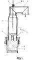
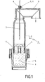
- the Fig. 1 shows a total designated 1 Vakuumum securedtgasungsstrom.
- This consists of a vacuum vessel 2 or RH vessel, which merges in its upper part in a leading to a vacuum pump Dom 3.
- the vacuum housing 2 is equipped with two dip tubes 4, which dip into a melt located in a pan 5 6. Through one of the dip tubes 4, the melt 6 rises from the open pan 5 in the vacuum housing 2 and through the other dip tube 4, the melt 6 flows back into the pan 5.
- the melt 6 is subjected to a metallurgical treatment under vacuum applied. In particular, the melt 6 is exposed during vacuum refining to a blown through a lance 7 oxygen flow.
- the lance 7 is a blow lance that is equipped as a combination lance with both an oxygen inflation function for the release of oxygen and a burner function.
- the lance 7 is arranged vertically displaceable in the vacuum housing 2 and guided in a vacuum-tight passage 8, which is usually designed as an inflatable seal. Except for Hood or the dome 3 is formed on this top side an ignition chamber 9, in which the lance 7 is guided centrally.
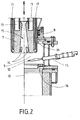
- the tip of the blowing lance 7 is shown in sectional view, wherein the other substantially cylindrically shaped components of the ignition chamber and the Domstutzens are shown only on one side of the longitudinal axis 10. With the longitudinal axis 10 as a mirror axis but they also repeat on the other side.
- the longitudinal axis 10 as a mirror axis but they also repeat on the other side.
- the ignition chamber 9 opens a pilot burner 11 with its pilot flame 12, the fuel gas oxygen mixture of the main flame, which emerges from the lance 7, is ignited.
- the fuel gas via channels 13 with outlet openings 14 and the oxygen is supplied and discharged centrally via a mouth opening 15.
- the lance 7 is guided vertically through the ignition chamber 9 down into the interior of the vacuum vessel 2, so that there the main flame can then be raised to full load or rated load and can take over their heat-emitting function.
- no fuel gas but only oxygen for metallurgical treatment of the melt 6 is ejected from the mouth opening 15 of the lance 7 and inflated onto the surface of the molten metal 6 within the vacuum vessel 2.
- the lance 7 In the area of its outer peripheral wall, the lance 7 has common cooling water channels 17. Due to the vertical mobility and displaceability or movability of the lance 7 in the vacuum vessel 2 and in the ignition chamber 9 of the pilot burner 11 can be brought into the various relative positions to the lance 7. In addition to the vacuum-tight bushing 8 forming, annular seal in the ignition chamber 9 also two on the outer wall of the lance 7 abutting scraper 16 are formed.
Landscapes
- Chemical & Material Sciences (AREA)
- Engineering & Computer Science (AREA)
- Health & Medical Sciences (AREA)
- Materials Engineering (AREA)
- Metallurgy (AREA)
- Organic Chemistry (AREA)
- Pharmacology & Pharmacy (AREA)
- Medicinal Chemistry (AREA)
- Oil, Petroleum & Natural Gas (AREA)
- Epidemiology (AREA)
- Life Sciences & Earth Sciences (AREA)
- Animal Behavior & Ethology (AREA)
- General Health & Medical Sciences (AREA)
- Public Health (AREA)
- Veterinary Medicine (AREA)
- Manufacturing & Machinery (AREA)
- Mechanical Engineering (AREA)
- General Engineering & Computer Science (AREA)
- Treatment Of Steel In Its Molten State (AREA)
Description
Die Erfindung richtet sich auf eine Vakuumumlaufentgasungsanlage umfassend ein Vakuumgefäß mit einem an eine Vakuumpumpe anschließbaren Dom und zwei in die Schmelze einer zugeordneten Pfanne eintauchbaren Tauchrohren sowie mit einer in dem Vakuumgefäß verschiebbar positionierbaren Blaslanze mit kombinierter Sauerstoffaufblas- und Brennerfunktion, wobei der Blaslanze ein Zündbrenner zugeordnet ist.The invention is directed to a Vakuumumlaufentgasungsanlage comprising a vacuum vessel with a connectable to a vacuum pump dome and two submerged in the melt of an associated pan dip tubes and with a slidably positionable in the vacuum vessel lance with combined Sauerstoffaufblas- and burner function, wherein the lance is associated with a pilot burner ,
Zum Behandeln von Metall-, insbesondere Stahlschmelzen durch Aufblasen von Sauerstoff auf die Oberfläche einer in einem Vakuumgefäß befindlichen Schmelze ist im Verlaufe der letzten Jahrzehnte die Vakuumbehandlung als sekundärmetallurgisches Verfahren immer weiterentwickelt worden. Die Vakuumbehandlung dient dazu, die Restgehalte an unerwünschten Begleitelementen in der Schmelze weitestgehend zu verringern, einen möglichst hohen Reinheitsgrad der Schmelze zu erreichen sowie die Zusammensetzung des Stahls möglichst genau einzustellen und die Homogenität des erstarrten Stahls zu verbessern. Für das Vakuumfrischen steht als Vakuumbehandlung unter anderem die sogenannte Umlauf-Entgasung, häufig auch als RH-Verfahren bezeichnet, zur Verfügung. Bei diesem Verfahren wird unter anderem gasförmiger Sauerstoff mit Hilfe einer wassergekühlten Lanze auf die im Vakuumgefäß befindliche Schmelze geblasen, wobei unter Vakuum dann metallurgische Prozesse ablaufen, die zu einer Qualitätsverbesserung des behandelten Flüssigstahls führen. Kernstück einer solchen Anlage ist ein Vakuumgefäß mit einer an eine Vakuumpumpe angeschlossenem Dom. Mit zwei Tauchrohren taucht das Vakuumgefäß in die flüssige Schmelze einer Pfanne ein, wobei nach Erzeugung eines Vakuums ein Umlauf der Schmelze von der Pfanne durch ein Tauchrohr in das Vakuumgefäß und durch das andere Tauchrohr zurück in die Schmelze erzeugt wird. Das Vakuumgefäß muss vor Durchführung einer Behandlung der Schmelze jeweils aufgewärmt werden, zwischen Behandlungszyklen in den Behandlungspausen warmgehalten und ggf. nach Behandlungsende gereinigt werden. Um mit einer Lanze sowohl das Sauerstoffaufblasen auf die Schmelze im Vakuumgefäß durchführen zu können, als auch mit dieser Lanze die notwendige Beheizung und Erwärmung des Vakuumgefäßes durchführen zu können, werden heutzutage üblicherweise Blaslanzen mit kombinierter Sauerstoffaufblas- und Brennerfunktion verwendet, durch welche hindurch sowohl ein Brenngas ausgestoßen und im Mündungsbereich der Blaslanze zu einer Flamme gezündet werden kann als auch ein Sauerstoffstrahl auf die Schmelze geblasen werden kann. Die Blaslanze ist in dem Vakuumgefäß axial verschiebbar angeordnet und dabei durch eine vakuumdichte Durchführung im Dom geführt. Üblicherweise ist eine solche Kombi-Blaslanze mit einem integrierten Zündbrenner ausgestattet. Derartige Kombi-Lanzen dürfen ab einer bestimmten Leistung nicht direkt gezündet werden, sondern müssen durch einen Zündbrenner gezündet werden, der nach Zünden seiner Zündflamme und nach Erkennen dieser Zündflamme Brennstoffgas und Sauerstoff in der Kombi-Blaslanze zur Zündung der Hauptflamme freigibt. Bei den bekannten Kombi-Blaslanzen ist dieser Zündbrenner unmittelbar an der Spitze der Kombi-Blaslanze in unmittelbarer Nähe der Gas- und Sauerstoffaustritte für die Hauptflamme ausgebildet. Der Zündbrenner ist daher den Umgebungsbedingungen, in die sich die Kombi-Blaslanze begibt, unmittelbar ausgesetzt. In der Sauerstoffaufblasfunktion der Kombi-Lanze führt dies dazu, dass Stahl- und/oder Schlackespritzer in den oder an den Zündbrenner gelangen können. Dies führt häufig zu einem Ausfall des Zündbrenners und damit zu einem Ausfall der Brennerfunktion der Kombi-Lanze, die dann zeitaufwändig gereinigt und/oder gewechselt werden muss, was bei entsprechendem Produktionsausfall äußerst kostspielig ist.For treating metal, in particular molten steel, by blowing oxygen onto the surface of a melt contained in a vacuum vessel, the vacuum treatment as a secondary metallurgical process has always been developed over the last decades. The vacuum treatment serves to reduce the residual contents of unwanted accompanying elements in the melt as much as possible, to achieve the highest possible degree of purity of the melt and to adjust the composition of the steel as accurately as possible and to improve the homogeneity of the solidified steel. For vacuum refining, the so-called recirculation degassing, frequently referred to as RH process, is available as a vacuum treatment. In this method, among other things, gaseous oxygen is blown onto the melt contained in the vacuum vessel with the aid of a water-cooled lance, whereby under vacuum metallurgical processes take place which lead to an improvement in the quality of the treated liquid steel. The core of such a system is a vacuum vessel with a dome connected to a vacuum pump. With two dip tubes, the vacuum vessel immersed in the liquid melt of a pan, wherein after generation of a vacuum, a circulation of the melt from the pan through a dip tube into the vacuum vessel and through the another dip tube is created back into the melt. The vacuum vessel must in each case be warmed up before carrying out a treatment of the melt, kept warm between treatment cycles during the treatment pauses and, if necessary, cleaned after the end of the treatment. In order to carry out with a lance both the oxygen blowing on the melt in the vacuum vessel, as well as to carry out the necessary heating and heating of the vacuum vessel with this lance, nowadays usually blow lances are used with combined Sauerstoffaufblas- and burner function, through which both a fuel gas ejected and ignited in the mouth region of the lance to a flame as well as an oxygen jet can be blown onto the melt. The lance is arranged axially displaceable in the vacuum vessel and thereby guided by a vacuum-tight implementation in the cathedral. Usually, such a combi-lance is equipped with an integrated pilot burner. Such combination lances must not be ignited directly from a certain power, but must be ignited by a pilot burner, which releases after ignition of its pilot flame and after detection of this pilot flame fuel gas and oxygen in the combination lance to ignite the main flame. In the known combination blow lances of this pilot burner is formed directly at the top of the combi lance in the immediate vicinity of the gas and oxygen outlets for the main flame. The pilot burner is therefore exposed directly to the ambient conditions in which the combi-blowgun goes. In the oxygen inflation function of the combination lance, this leads to steel and / or slag spatter getting into or onto the pilot burner. This often leads to failure of the pilot burner and thus to a failure of the burner function of the combination lance, which is then time-consuming cleaned and / or replaced must be what is very costly in case of corresponding loss of production.
Eine gattungsgemäße Vakuumumlaufentgasungsanlage ist aus der
Diese daraus bekannten Vakuumumlaufentgasungsanlagen weisen die vorstehend dargelegten Nachteile auf.These known vacuum recirculation degassing systems have the disadvantages set out above.
Aus der
Blaslanzen mit kombinierter Sauerstoffaufblas- und Brennerfunktion sind zudem aus den in der
Der Erfindung liegt die Aufgabe zugrunde, eine Lösung zu schaffen, die es ermöglicht, eine erhöhte Blaslanzen- und Anlagenverfügbarkeit bei einer Vakuumumlaufentgasungsanlage zu erzielen.The invention has for its object to provide a solution that makes it possible to achieve increased Blaslanzen- and plant availability in a Vakuumumlaufentgasungsanlage.
Bei einer Vakuumumlaufentgasungsanlage der eingangs näher bezeichneten Art wird diese Aufgabe erfindungsgemäß dadurch gelöst, dass der Zündbrenner in einer Zündkammer angeordnet ist, in welcher er insbesondere durch Verfahren der Blaslanze in verschiedene Relativlagen zur Blaslanze bringbar ist.In a Vakuumumlaufentgasungsanlage of the type described in more detail, this object is achieved in that the Zündbrenner arranged in an ignition chamber is, in which he can be brought in particular relative to the blow lance in particular by moving the lance in different relative positions.
Der Zündbrenner wird erfindungsgemäß in einer vorzugsweise außerhalb des eigentlichen metallurgischen Behandlungsraumes des Vakuumgefäßes der Vakuumumlaufentgasungsanlage ausgebildeten Zündkammer angeordnet, durch welche die Kombi-Blaslanze hindurchbewegbar ist. Auf diese Weise lässt sich der Zündbrenner insbesondere durch Verfahren der Blaslanze in verschiedene Relativlagen zur Blaslanze bringen. Dies ermöglicht es, den Zündbrenner in einem von den übrigen Umgebungsbedingungen innerhalb des Vakuumgefäßes geschützten und in Relation zu den innerhalb des Vakuumgefäßes entstehenden Temperaturen mäßig warmen Raum anzuordnen, in welchem der Zündbrenner nur bis zur Zündung der Hauptflamme der Blaslanze einer erhöhten Temperatur ausgesetzt ist. Hierzu wird die Blaslanze zunächst in eine Zündposition innerhalb der Zündkammer hochgefahren, in welcher sie oberhalb des Zündbrenners positioniert ist. Nach Erkennung der Zündflamme des Zündbrenners wird dann durch eine übliche Flammenüberwachung die notwendige minimale Brenngaszufuhr und Sauerstoffzufuhr in die Blaslanze zur Zündung der Hauptflamme der Blaslanze mit Minimallast freigegeben. Sobald ein Sensor das Zünden und Brennen der Hauptflamme der Blaslanze erkennt, wird die Zündflamme des Zündbrenners ausgeschaltet und die Blaslanze in ihren Arbeitsbereich innerhalb des Vakuumgefäßes abgesenkt. In dieser abgesenkten Arbeitsposition wird dann die Brennstoffgas- und Sauerstoffzufuhr soweit gesteigert und derart eingestellt bis die Blaslanze dann in ihrer Brennerfunktion mit Nennlast oder Maximallast betrieben wird.The pilot burner is arranged according to the invention in a preferably formed outside of the actual metallurgical treatment chamber of the vacuum vessel of Vakuumumlaufentgasungsanlage ignition chamber through which the combination blowgun is hindurchbewegbar. In this way, the pilot burner can be brought into different relative positions to the lance, in particular by moving the lance. This makes it possible to arrange the pilot burner in a moderately warm space in a protected from the other environmental conditions within the vacuum vessel and in relation to the resulting within the vacuum vessel temperatures in which the pilot burner is exposed only to the ignition of the main flame of the lance of an elevated temperature. For this purpose, the lance is first raised to an ignition position within the ignition chamber, in which it is positioned above the pilot burner. After detection of the ignition flame of the pilot burner, the necessary minimum fuel gas supply and oxygen supply to the lance for ignition of the main flame of the lance is then released by a standard flame monitoring with minimum load. As soon as a sensor detects the ignition and burning of the main flame of the lance, the pilot flame of the pilot burner is turned off and lowered the lance into its working range within the vacuum vessel. In this lowered working position, the fuel gas and oxygen supply is then increased and adjusted so far until the lance is then operated in its burner function with rated load or maximum load.
Dadurch, dass der Zündbrenner und die Blaslanze getrennt voneinander angeordnet und ausgebildet sowie in unterschiedliche Relativpositionen zueinander bringbar sind, wird es vermieden, dass es zu einem Ausfall der Blaslanze und damit der Anlage aufgrund den Zündbrenner erreichender Stahl- oder Schlackenspritzer kommt. Die Blaslanzen-, und damit Anlagenverfügbarkeit, wird dadurch erhöht. Außerdem ergeben sich kürzere Lanzen- und Zündbrennerwechselzeiten, da zum Lanzenwechseln kein in der Blaslanze integrierter Zündbrenner mit aus dem Vakuumgefäß herausgefahren werden muss, wozu dieser von Gas- und Sauerstoffzuführleitungen ggf. abgetrennt werden müsste. Andererseits lässt sich der Zündbrenner bei Ausfall wechseln, ohne dass dafür die Blaslanze bewegt oder aus dem Vakuumgefäß herausgefahren werden muss. Schließlich ergeben sich für die Blaslanze geringere Herstellkosten, da in diese kein Zündbrenner und diesem zuzuordnende Kühlvorrichtungen vorgesehen werden müssen. Da die Blaslanze nicht mehr mit einem integrierten Zündbrenner versehen ist, lässt sich dadurch der Lanzendurchmesser verringern, was einen verringerten Kühlwasserbedarf und damit einen geringeren Verbrauch an Betriebsmittel mit sich bringt. Außerdem ist nur noch eine geringere Antriebsleistung für das Auf- und Abfahren der Blaslanze erforderlich, da diese dann auch ein geringeres Gewicht aufweist.Characterized in that the pilot burner and the lance are arranged separately from each other and formed and in different relative positions can be brought to each other, it is avoided that there is a failure of the lance and so that the plant comes due to the pilot burner reaching steel or slag splash. The blowgun, and thus plant availability, is thereby increased. In addition, shorter lance and Zündbrennerwechselzeiten arise because the Lanzwechseln no integrated in the lance pilot with the out of the vacuum vessel must be moved out what this would have to be separated from gas and Sauerstoffzuführleitungen if necessary. On the other hand, the pilot burner can be changed in the event of failure without having to move the lance or remove it from the vacuum vessel. Finally, lower production costs result for the lance because no pilot burner and cooling devices that are to be associated with them have to be provided. Since the lance is no longer provided with an integrated pilot burner, this can reduce the lance diameter, resulting in a reduced cooling water requirement and thus a lower consumption of resources with it. In addition, only a lower drive power for the raising and lowering of the lance is required, as this then also has a lower weight.
Eine besonders zweckmäßige Anordnung der Zündkammer ist die Platzierung oben auf dem Dom des Vakuumgefäßes auf der dem Vakuumgefäßinnenraum abgewandten Seite. Hierdurch ist es möglich, die senkrecht oder vertikal in dem Vakuumgefäß verfahrbare Blaslanze ohne wesentliche Veränderungen am üblichen Mechanismus zur Verfahrbarkeit der Lanze vornehmen zu müssen in den Bereich des Zündbrenners zu verfahren. Es ist aber auch möglich, die Zündkammer am Dom oder am RH-Gefäß bzw. am Vakuumgefäß anzuordnen. Die Erfindung sieht daher weiterhin vor, dass die Zündkammer auf dem Dom oder am Vakuumgefäß ausgebildet ist.A particularly expedient arrangement of the ignition chamber is the placement on top of the dome of the vacuum vessel on the side facing away from the vacuum vessel interior. This makes it possible to make the vertical or vertical movable in the vacuum vessel blow lance without making significant changes to the usual mechanism for the mobility of the lance to proceed in the field of pilot burner. However, it is also possible to arrange the ignition chamber on the dome or on the RH vessel or on the vacuum vessel. The invention therefore further provides that the ignition chamber is formed on the dome or on the vacuum vessel.
Ganz besonders zweckmäßig lässt sich hierbei auch die vakuumdichte Durchführung der Blaslanze in das Vakuumgefäß hinein im Bereich der Zündkammer vorsehen. Die Erfindung zeichnet sich schließlich auch dadurch aus, dass an der Zündkammer eine vakuumdichte Durchführung der Blaslanze ausgebildet ist.In this case, the vacuum-tight passage of the lance into the vacuum vessel can also be used particularly expediently Provide in the area of the ignition chamber. Finally, the invention is also distinguished by the fact that a vacuum-tight passage of the blowing lance is formed on the ignition chamber.
Die Erfindung ist nachstehend anhand der Zeichnung beispielhaft näher erläutert. Diese zeigt in
- Fig. 1
- in schematischer Schnittdarstellung eine Vakuumumlaufentgasungsanlage mit einer Zündkammer und in
- Fig. 2
- in schematischer Teilschnittdarstellung eine Zündkammer mit Zündbrenner.
- Fig. 1
- in a schematic sectional view of a Vakuumumlaufentgasungsanlage with an ignition chamber and in
- Fig. 2
- in a schematic partial sectional view of an ignition chamber with pilot burner.
Die
Claims (3)
- Vacuum circulation degassing system (1), comprising a vacuum vessel (2) with dome (3) connectable to a vacuum pump and two immersible tubes (4) that can be submersed in the melt (6) of an associated ladle (5), and with a blower lance (7) displaceably positionable in the vacuum vessel (2) with a combined oxygen blowing and burner function, wherein an ignition burner (11) is allocated to the blower lance (7),
characterised in that
the ignition burner (11) is arranged in an ignition chamber (9), in which it can be brought into various positions relative to the blower lance (7), in particular through displacing the blower lance (7). - Vacuum circulation degassing system (1) according to claim 1, characterised in that the ignition chamber (9) is formed on the dome (3) or on the vacuum vessel (2).
- Vacuum circulation degassing system (1) according to claim 1 or 2, characterised in that a vacuum-tight passage (8) of the blower lance (7) is formed on the ignition chamber (9).
Applications Claiming Priority (1)
| Application Number | Priority Date | Filing Date | Title |
|---|---|---|---|
| DE102010007119A DE102010007119B3 (en) | 2010-02-05 | 2010-02-05 | Vakuumumlaufentgasungsanlage with pilot burner |
Publications (2)
| Publication Number | Publication Date |
|---|---|
| EP2354259A1 EP2354259A1 (en) | 2011-08-10 |
| EP2354259B1 true EP2354259B1 (en) | 2018-03-14 |
Family
ID=44010095
Family Applications (1)
| Application Number | Title | Priority Date | Filing Date |
|---|---|---|---|
| EP11152764.4A Active EP2354259B1 (en) | 2010-02-05 | 2011-01-31 | Vacuum circulation gas removal assembly with ignitor |
Country Status (7)
| Country | Link |
|---|---|
| EP (1) | EP2354259B1 (en) |
| KR (1) | KR20110091486A (en) |
| CN (1) | CN102146503B (en) |
| BR (1) | BRPI1100201B1 (en) |
| DE (1) | DE102010007119B3 (en) |
| RU (1) | RU2450058C1 (en) |
| TW (1) | TWI443196B (en) |
Families Citing this family (2)
| Publication number | Priority date | Publication date | Assignee | Title |
|---|---|---|---|---|
| EP2581462B1 (en) | 2011-10-10 | 2016-03-02 | Primetals Technologies Germany GmbH | Blowing lance with direct ignition through retractable ignition lance |
| CN103822346B (en) * | 2014-02-24 | 2016-06-29 | 李博平 | A kind of submersible burner and method |
Family Cites Families (7)
| Publication number | Priority date | Publication date | Assignee | Title |
|---|---|---|---|---|
| AT299283B (en) * | 1969-04-08 | 1972-06-12 | Voest Ag | Process for controlling the operation of oxygen inflation processes |
| SU1617027A1 (en) * | 1988-11-18 | 1990-12-30 | Всесоюзный научно-исследовательский и проектно-конструкторский институт металлургического машиностроения им.А.И.Целикова | Arrangement for cooling gases in evacuation |
| SU1735358A1 (en) * | 1990-04-28 | 1992-05-23 | Институт Ботаники Им.Н.Г.Холодного | Nutrient medium for cultivation of basidiomycetes - producers of enzyme complexes, degrading lignocellulose raw |
| JPH08325630A (en) * | 1995-05-31 | 1996-12-10 | Sumitomo Metal Ind Ltd | Lance device for refining |
| DE19811722C1 (en) * | 1998-03-18 | 1999-09-09 | Sms Vacmetal Ges Fuer Vacuumme | Apparatus for vacuum refining of metal, in particular, steel melts |
| WO2000068442A1 (en) * | 1999-05-07 | 2000-11-16 | Sidmar N.V. | Method of decarburisation and dephosphorisation of a molten metal |
| JP3666301B2 (en) * | 1999-05-21 | 2005-06-29 | Jfeスチール株式会社 | Compound lance for vacuum degassing tank and method of using the same |
-
2010
- 2010-02-05 DE DE102010007119A patent/DE102010007119B3/en not_active Expired - Fee Related
-
2011
- 2011-01-31 EP EP11152764.4A patent/EP2354259B1/en active Active
- 2011-02-01 TW TW100103889A patent/TWI443196B/en not_active IP Right Cessation
- 2011-02-01 CN CN201110036865.XA patent/CN102146503B/en active Active
- 2011-02-03 RU RU2011103723/02A patent/RU2450058C1/en active
- 2011-02-07 KR KR1020110010482A patent/KR20110091486A/en not_active Application Discontinuation
- 2011-02-07 BR BRPI1100201-8A patent/BRPI1100201B1/en active IP Right Grant
Non-Patent Citations (1)
| Title |
|---|
| None * |
Also Published As
| Publication number | Publication date |
|---|---|
| BRPI1100201B1 (en) | 2018-03-13 |
| BRPI1100201A2 (en) | 2012-07-24 |
| EP2354259A1 (en) | 2011-08-10 |
| RU2450058C1 (en) | 2012-05-10 |
| TWI443196B (en) | 2014-07-01 |
| CN102146503B (en) | 2015-02-25 |
| KR20110091486A (en) | 2011-08-11 |
| TW201132765A (en) | 2011-10-01 |
| DE102010007119B3 (en) | 2011-07-28 |
| CN102146503A (en) | 2011-08-10 |
Similar Documents
| Publication | Publication Date | Title |
|---|---|---|
| DE69032804T2 (en) | Blow lance with cladding tube | |
| DE2737832C3 (en) | Use of blower nozzles with variable cross-section for the production of stainless steels | |
| EP3892947B1 (en) | Device and method for maintaining the tap hole of an electric arc furnace | |
| DE69132590T2 (en) | Refining furnace for copper | |
| EP0487494B1 (en) | Plant for the production of molten metals | |
| DE3019811C2 (en) | Discharge controller for a melting furnace | |
| DE2821453B2 (en) | Plasma melting furnace | |
| EP2354259B1 (en) | Vacuum circulation gas removal assembly with ignitor | |
| DE19817590C1 (en) | Combination lance for treatment of metallurgical melts | |
| EP0180741A1 (en) | Process and installation for maintaining or increasing the temperature of a metal melt | |
| EP1613130A1 (en) | Electrode system for glass melting furnace | |
| EP2318559B1 (en) | Copper anode furnace | |
| DE1924812C3 (en) | Burner lance for a metallurgical furnace and method for operating such a furnace with this burner lance | |
| EP1613131A1 (en) | Electrode system for glass melting furnace | |
| AT394211B (en) | PLANT FOR PRODUCING LIQUID METALS AND METHOD FOR PRODUCING A METAL MELT, IN PARTICULAR STEEL WITH THIS PLANT | |
| DE19729317A1 (en) | Water-cooled pan hood | |
| DE2834737A1 (en) | STEEL MANUFACTURING PROCESS | |
| EP2853610B1 (en) | Device and method for electro-slag remelting | |
| EP1835039B1 (en) | Smelting unit, comprising an injector, a lance or a burner | |
| DE19811722C1 (en) | Apparatus for vacuum refining of metal, in particular, steel melts | |
| EP3473733A1 (en) | Intermediate container for separation of slag | |
| WO2000061823A1 (en) | Method and device for tapping molten metal from metallurgical vessels | |
| AT387404B (en) | Method for determining the residual thickness of refractory bricks, and refractory brick for carrying out this method | |
| DE2951826C2 (en) | Metallurgical melting and refining unit | |
| AT203528B (en) | Hearth furnace, especially Siemens-Martin furnace, for the production of steel |
Legal Events
| Date | Code | Title | Description |
|---|---|---|---|
| PUAI | Public reference made under article 153(3) epc to a published international application that has entered the european phase |
Free format text: ORIGINAL CODE: 0009012 |
|
| AK | Designated contracting states |
Kind code of ref document: A1 Designated state(s): AL AT BE BG CH CY CZ DE DK EE ES FI FR GB GR HR HU IE IS IT LI LT LU LV MC MK MT NL NO PL PT RO RS SE SI SK SM TR |
|
| AX | Request for extension of the european patent |
Extension state: BA ME |
|
| 17P | Request for examination filed |
Effective date: 20120127 |
|
| 17Q | First examination report despatched |
Effective date: 20160620 |
|
| RAP1 | Party data changed (applicant data changed or rights of an application transferred) |
Owner name: TENOVA METALS DEUTSCHLAND GMBH |
|
| STAA | Information on the status of an ep patent application or granted ep patent |
Free format text: STATUS: EXAMINATION IS IN PROGRESS |
|
| GRAP | Despatch of communication of intention to grant a patent |
Free format text: ORIGINAL CODE: EPIDOSNIGR1 |
|
| STAA | Information on the status of an ep patent application or granted ep patent |
Free format text: STATUS: GRANT OF PATENT IS INTENDED |
|
| INTG | Intention to grant announced |
Effective date: 20170913 |
|
| GRAS | Grant fee paid |
Free format text: ORIGINAL CODE: EPIDOSNIGR3 |
|
| GRAA | (expected) grant |
Free format text: ORIGINAL CODE: 0009210 |
|
| STAA | Information on the status of an ep patent application or granted ep patent |
Free format text: STATUS: THE PATENT HAS BEEN GRANTED |
|
| AK | Designated contracting states |
Kind code of ref document: B1 Designated state(s): AL AT BE BG CH CY CZ DE DK EE ES FI FR GB GR HR HU IE IS IT LI LT LU LV MC MK MT NL NO PL PT RO RS SE SI SK SM TR |
|
| REG | Reference to a national code |
Ref country code: GB Ref legal event code: FG4D Free format text: NOT ENGLISH |
|
| REG | Reference to a national code |
Ref country code: CH Ref legal event code: EP Ref country code: AT Ref legal event code: REF Ref document number: 978931 Country of ref document: AT Kind code of ref document: T Effective date: 20180315 |
|
| REG | Reference to a national code |
Ref country code: IE Ref legal event code: FG4D Free format text: LANGUAGE OF EP DOCUMENT: GERMAN |
|
| REG | Reference to a national code |
Ref country code: DE Ref legal event code: R096 Ref document number: 502011013885 Country of ref document: DE |
|
| REG | Reference to a national code |
Ref country code: RO Ref legal event code: EPE |
|
| REG | Reference to a national code |
Ref country code: NL Ref legal event code: MP Effective date: 20180314 |
|
| REG | Reference to a national code |
Ref country code: LT Ref legal event code: MG4D |
|
| PG25 | Lapsed in a contracting state [announced via postgrant information from national office to epo] |
Ref country code: NO Free format text: LAPSE BECAUSE OF FAILURE TO SUBMIT A TRANSLATION OF THE DESCRIPTION OR TO PAY THE FEE WITHIN THE PRESCRIBED TIME-LIMIT Effective date: 20180614 Ref country code: LT Free format text: LAPSE BECAUSE OF FAILURE TO SUBMIT A TRANSLATION OF THE DESCRIPTION OR TO PAY THE FEE WITHIN THE PRESCRIBED TIME-LIMIT Effective date: 20180314 Ref country code: FI Free format text: LAPSE BECAUSE OF FAILURE TO SUBMIT A TRANSLATION OF THE DESCRIPTION OR TO PAY THE FEE WITHIN THE PRESCRIBED TIME-LIMIT Effective date: 20180314 Ref country code: HR Free format text: LAPSE BECAUSE OF FAILURE TO SUBMIT A TRANSLATION OF THE DESCRIPTION OR TO PAY THE FEE WITHIN THE PRESCRIBED TIME-LIMIT Effective date: 20180314 Ref country code: ES Free format text: LAPSE BECAUSE OF FAILURE TO SUBMIT A TRANSLATION OF THE DESCRIPTION OR TO PAY THE FEE WITHIN THE PRESCRIBED TIME-LIMIT Effective date: 20180314 Ref country code: CY Free format text: LAPSE BECAUSE OF FAILURE TO SUBMIT A TRANSLATION OF THE DESCRIPTION OR TO PAY THE FEE WITHIN THE PRESCRIBED TIME-LIMIT Effective date: 20180314 |
|
| PG25 | Lapsed in a contracting state [announced via postgrant information from national office to epo] |
Ref country code: RS Free format text: LAPSE BECAUSE OF FAILURE TO SUBMIT A TRANSLATION OF THE DESCRIPTION OR TO PAY THE FEE WITHIN THE PRESCRIBED TIME-LIMIT Effective date: 20180314 Ref country code: SE Free format text: LAPSE BECAUSE OF FAILURE TO SUBMIT A TRANSLATION OF THE DESCRIPTION OR TO PAY THE FEE WITHIN THE PRESCRIBED TIME-LIMIT Effective date: 20180314 Ref country code: LV Free format text: LAPSE BECAUSE OF FAILURE TO SUBMIT A TRANSLATION OF THE DESCRIPTION OR TO PAY THE FEE WITHIN THE PRESCRIBED TIME-LIMIT Effective date: 20180314 Ref country code: GR Free format text: LAPSE BECAUSE OF FAILURE TO SUBMIT A TRANSLATION OF THE DESCRIPTION OR TO PAY THE FEE WITHIN THE PRESCRIBED TIME-LIMIT Effective date: 20180615 Ref country code: BG Free format text: LAPSE BECAUSE OF FAILURE TO SUBMIT A TRANSLATION OF THE DESCRIPTION OR TO PAY THE FEE WITHIN THE PRESCRIBED TIME-LIMIT Effective date: 20180614 |
|
| PG25 | Lapsed in a contracting state [announced via postgrant information from national office to epo] |
Ref country code: MT Free format text: LAPSE BECAUSE OF FAILURE TO SUBMIT A TRANSLATION OF THE DESCRIPTION OR TO PAY THE FEE WITHIN THE PRESCRIBED TIME-LIMIT Effective date: 20180314 |
|
| PG25 | Lapsed in a contracting state [announced via postgrant information from national office to epo] |
Ref country code: EE Free format text: LAPSE BECAUSE OF FAILURE TO SUBMIT A TRANSLATION OF THE DESCRIPTION OR TO PAY THE FEE WITHIN THE PRESCRIBED TIME-LIMIT Effective date: 20180314 Ref country code: AL Free format text: LAPSE BECAUSE OF FAILURE TO SUBMIT A TRANSLATION OF THE DESCRIPTION OR TO PAY THE FEE WITHIN THE PRESCRIBED TIME-LIMIT Effective date: 20180314 Ref country code: PL Free format text: LAPSE BECAUSE OF FAILURE TO SUBMIT A TRANSLATION OF THE DESCRIPTION OR TO PAY THE FEE WITHIN THE PRESCRIBED TIME-LIMIT Effective date: 20180314 Ref country code: NL Free format text: LAPSE BECAUSE OF FAILURE TO SUBMIT A TRANSLATION OF THE DESCRIPTION OR TO PAY THE FEE WITHIN THE PRESCRIBED TIME-LIMIT Effective date: 20180314 |
|
| PG25 | Lapsed in a contracting state [announced via postgrant information from national office to epo] |
Ref country code: CZ Free format text: LAPSE BECAUSE OF FAILURE TO SUBMIT A TRANSLATION OF THE DESCRIPTION OR TO PAY THE FEE WITHIN THE PRESCRIBED TIME-LIMIT Effective date: 20180314 Ref country code: SK Free format text: LAPSE BECAUSE OF FAILURE TO SUBMIT A TRANSLATION OF THE DESCRIPTION OR TO PAY THE FEE WITHIN THE PRESCRIBED TIME-LIMIT Effective date: 20180314 Ref country code: SM Free format text: LAPSE BECAUSE OF FAILURE TO SUBMIT A TRANSLATION OF THE DESCRIPTION OR TO PAY THE FEE WITHIN THE PRESCRIBED TIME-LIMIT Effective date: 20180314 |
|
| REG | Reference to a national code |
Ref country code: DE Ref legal event code: R097 Ref document number: 502011013885 Country of ref document: DE |
|
| PG25 | Lapsed in a contracting state [announced via postgrant information from national office to epo] |
Ref country code: PT Free format text: LAPSE BECAUSE OF FAILURE TO SUBMIT A TRANSLATION OF THE DESCRIPTION OR TO PAY THE FEE WITHIN THE PRESCRIBED TIME-LIMIT Effective date: 20180716 |
|
| PLBE | No opposition filed within time limit |
Free format text: ORIGINAL CODE: 0009261 |
|
| STAA | Information on the status of an ep patent application or granted ep patent |
Free format text: STATUS: NO OPPOSITION FILED WITHIN TIME LIMIT |
|
| PG25 | Lapsed in a contracting state [announced via postgrant information from national office to epo] |
Ref country code: DK Free format text: LAPSE BECAUSE OF FAILURE TO SUBMIT A TRANSLATION OF THE DESCRIPTION OR TO PAY THE FEE WITHIN THE PRESCRIBED TIME-LIMIT Effective date: 20180314 |
|
| 26N | No opposition filed |
Effective date: 20181217 |
|
| PG25 | Lapsed in a contracting state [announced via postgrant information from national office to epo] |
Ref country code: SI Free format text: LAPSE BECAUSE OF FAILURE TO SUBMIT A TRANSLATION OF THE DESCRIPTION OR TO PAY THE FEE WITHIN THE PRESCRIBED TIME-LIMIT Effective date: 20180314 Ref country code: IT Free format text: LAPSE BECAUSE OF FAILURE TO SUBMIT A TRANSLATION OF THE DESCRIPTION OR TO PAY THE FEE WITHIN THE PRESCRIBED TIME-LIMIT Effective date: 20180314 |
|
| PG25 | Lapsed in a contracting state [announced via postgrant information from national office to epo] |
Ref country code: MC Free format text: LAPSE BECAUSE OF FAILURE TO SUBMIT A TRANSLATION OF THE DESCRIPTION OR TO PAY THE FEE WITHIN THE PRESCRIBED TIME-LIMIT Effective date: 20180314 |
|
| PG25 | Lapsed in a contracting state [announced via postgrant information from national office to epo] |
Ref country code: LU Free format text: LAPSE BECAUSE OF NON-PAYMENT OF DUE FEES Effective date: 20190131 |
|
| REG | Reference to a national code |
Ref country code: BE Ref legal event code: MM Effective date: 20190131 |
|
| REG | Reference to a national code |
Ref country code: IE Ref legal event code: MM4A |
|
| PG25 | Lapsed in a contracting state [announced via postgrant information from national office to epo] |
Ref country code: FR Free format text: LAPSE BECAUSE OF NON-PAYMENT OF DUE FEES Effective date: 20190131 |
|
| PG25 | Lapsed in a contracting state [announced via postgrant information from national office to epo] |
Ref country code: BE Free format text: LAPSE BECAUSE OF NON-PAYMENT OF DUE FEES Effective date: 20190131 |
|
| PG25 | Lapsed in a contracting state [announced via postgrant information from national office to epo] |
Ref country code: IE Free format text: LAPSE BECAUSE OF NON-PAYMENT OF DUE FEES Effective date: 20190131 |
|
| PG25 | Lapsed in a contracting state [announced via postgrant information from national office to epo] |
Ref country code: TR Free format text: LAPSE BECAUSE OF FAILURE TO SUBMIT A TRANSLATION OF THE DESCRIPTION OR TO PAY THE FEE WITHIN THE PRESCRIBED TIME-LIMIT Effective date: 20180314 |
|
| REG | Reference to a national code |
Ref country code: DE Ref legal event code: R082 Ref document number: 502011013885 Country of ref document: DE Representative=s name: VIERING, JENTSCHURA & PARTNER MBB PATENT- UND , DE Ref country code: DE Ref legal event code: R081 Ref document number: 502011013885 Country of ref document: DE Owner name: LOI THERMPROCESS GMBH, DE Free format text: FORMER OWNER: TENOVA METALS DEUTSCHLAND GMBH, 45141 ESSEN, DE |
|
| REG | Reference to a national code |
Ref country code: CH Ref legal event code: PFUS Owner name: LOI THERMPROCESS GMBH, DE Free format text: FORMER OWNER: TENOVA METALS DEUTSCHLAND GMBH, DE |
|
| REG | Reference to a national code |
Ref country code: GB Ref legal event code: 732E Free format text: REGISTERED BETWEEN 20200903 AND 20200910 |
|
| REG | Reference to a national code |
Ref country code: AT Ref legal event code: PC Ref document number: 978931 Country of ref document: AT Kind code of ref document: T Owner name: LOI THERMPROCESS GMBH, DE Effective date: 20201120 |
|
| PG25 | Lapsed in a contracting state [announced via postgrant information from national office to epo] |
Ref country code: IS Free format text: LAPSE BECAUSE OF FAILURE TO SUBMIT A TRANSLATION OF THE DESCRIPTION OR TO PAY THE FEE WITHIN THE PRESCRIBED TIME-LIMIT Effective date: 20180714 |
|
| PG25 | Lapsed in a contracting state [announced via postgrant information from national office to epo] |
Ref country code: HU Free format text: LAPSE BECAUSE OF FAILURE TO SUBMIT A TRANSLATION OF THE DESCRIPTION OR TO PAY THE FEE WITHIN THE PRESCRIBED TIME-LIMIT; INVALID AB INITIO Effective date: 20110131 |
|
| PGFP | Annual fee paid to national office [announced via postgrant information from national office to epo] |
Ref country code: GB Payment date: 20220125 Year of fee payment: 12 Ref country code: CH Payment date: 20220125 Year of fee payment: 12 Ref country code: AT Payment date: 20220119 Year of fee payment: 12 |
|
| PGFP | Annual fee paid to national office [announced via postgrant information from national office to epo] |
Ref country code: RO Payment date: 20220127 Year of fee payment: 12 |
|
| PG25 | Lapsed in a contracting state [announced via postgrant information from national office to epo] |
Ref country code: MK Free format text: LAPSE BECAUSE OF FAILURE TO SUBMIT A TRANSLATION OF THE DESCRIPTION OR TO PAY THE FEE WITHIN THE PRESCRIBED TIME-LIMIT Effective date: 20180314 |
|
| REG | Reference to a national code |
Ref country code: CH Ref legal event code: PL |
|
| REG | Reference to a national code |
Ref country code: AT Ref legal event code: MM01 Ref document number: 978931 Country of ref document: AT Kind code of ref document: T Effective date: 20230131 |
|
| GBPC | Gb: european patent ceased through non-payment of renewal fee |
Effective date: 20230131 |
|
| PG25 | Lapsed in a contracting state [announced via postgrant information from national office to epo] |
Ref country code: RO Free format text: LAPSE BECAUSE OF NON-PAYMENT OF DUE FEES Effective date: 20230131 Ref country code: LI Free format text: LAPSE BECAUSE OF NON-PAYMENT OF DUE FEES Effective date: 20230131 Ref country code: GB Free format text: LAPSE BECAUSE OF NON-PAYMENT OF DUE FEES Effective date: 20230131 Ref country code: CH Free format text: LAPSE BECAUSE OF NON-PAYMENT OF DUE FEES Effective date: 20230131 Ref country code: AT Free format text: LAPSE BECAUSE OF NON-PAYMENT OF DUE FEES Effective date: 20230131 |
|
| PGFP | Annual fee paid to national office [announced via postgrant information from national office to epo] |
Ref country code: DE Payment date: 20231219 Year of fee payment: 14 |