EP2354066A1 - Vorrichtung und Verfahren zum Fördern von Blättern - Google Patents
Vorrichtung und Verfahren zum Fördern von Blättern Download PDFInfo
- Publication number
- EP2354066A1 EP2354066A1 EP10152147A EP10152147A EP2354066A1 EP 2354066 A1 EP2354066 A1 EP 2354066A1 EP 10152147 A EP10152147 A EP 10152147A EP 10152147 A EP10152147 A EP 10152147A EP 2354066 A1 EP2354066 A1 EP 2354066A1
- Authority
- EP
- European Patent Office
- Prior art keywords
- gripping
- path
- circulation
- end portion
- paper feeding
- Prior art date
- Legal status (The legal status is an assumption and is not a legal conclusion. Google has not performed a legal analysis and makes no representation as to the accuracy of the status listed.)
- Withdrawn
Links
Images


Classifications
-
- B—PERFORMING OPERATIONS; TRANSPORTING
- B65—CONVEYING; PACKING; STORING; HANDLING THIN OR FILAMENTARY MATERIAL
- B65H—HANDLING THIN OR FILAMENTARY MATERIAL, e.g. SHEETS, WEBS, CABLES
- B65H29/00—Delivering or advancing articles from machines; Advancing articles to or into piles
- B65H29/02—Delivering or advancing articles from machines; Advancing articles to or into piles by mechanical grippers engaging the leading edge only of the articles
- B65H29/04—Delivering or advancing articles from machines; Advancing articles to or into piles by mechanical grippers engaging the leading edge only of the articles the grippers being carried by endless chains or bands
- B65H29/045—Details of grippers
-
- B—PERFORMING OPERATIONS; TRANSPORTING
- B65—CONVEYING; PACKING; STORING; HANDLING THIN OR FILAMENTARY MATERIAL
- B65H—HANDLING THIN OR FILAMENTARY MATERIAL, e.g. SHEETS, WEBS, CABLES
- B65H29/00—Delivering or advancing articles from machines; Advancing articles to or into piles
- B65H29/66—Advancing articles in overlapping streams
- B65H29/669—Advancing articles in overlapping streams ending an overlapping stream
-
- B—PERFORMING OPERATIONS; TRANSPORTING
- B65—CONVEYING; PACKING; STORING; HANDLING THIN OR FILAMENTARY MATERIAL
- B65H—HANDLING THIN OR FILAMENTARY MATERIAL, e.g. SHEETS, WEBS, CABLES
- B65H2301/00—Handling processes for sheets or webs
- B65H2301/40—Type of handling process
- B65H2301/44—Moving, forwarding, guiding material
- B65H2301/447—Moving, forwarding, guiding material transferring material between transport devices
- B65H2301/4471—Grippers, e.g. moved in paths enclosing an area
- B65H2301/44712—Grippers, e.g. moved in paths enclosing an area carried by chains or bands
-
- B—PERFORMING OPERATIONS; TRANSPORTING
- B65—CONVEYING; PACKING; STORING; HANDLING THIN OR FILAMENTARY MATERIAL
- B65H—HANDLING THIN OR FILAMENTARY MATERIAL, e.g. SHEETS, WEBS, CABLES
- B65H2301/00—Handling processes for sheets or webs
- B65H2301/40—Type of handling process
- B65H2301/44—Moving, forwarding, guiding material
- B65H2301/447—Moving, forwarding, guiding material transferring material between transport devices
- B65H2301/4474—Pair of cooperating moving elements as rollers, belts forming nip into which material is transported
-
- B—PERFORMING OPERATIONS; TRANSPORTING
- B65—CONVEYING; PACKING; STORING; HANDLING THIN OR FILAMENTARY MATERIAL
- B65H—HANDLING THIN OR FILAMENTARY MATERIAL, e.g. SHEETS, WEBS, CABLES
- B65H2405/00—Parts for holding the handled material
- B65H2405/50—Gripping means
- B65H2405/55—Rail guided gripping means running in closed loop, e.g. without permanent interconnecting means
- B65H2405/552—Rail guided gripping means running in closed loop, e.g. without permanent interconnecting means with permanent interconnection and determined spacing between the grippers
-
- B—PERFORMING OPERATIONS; TRANSPORTING
- B65—CONVEYING; PACKING; STORING; HANDLING THIN OR FILAMENTARY MATERIAL
- B65H—HANDLING THIN OR FILAMENTARY MATERIAL, e.g. SHEETS, WEBS, CABLES
- B65H2405/00—Parts for holding the handled material
- B65H2405/50—Gripping means
- B65H2405/58—Means for achieving gripping/releasing operation
-
- B—PERFORMING OPERATIONS; TRANSPORTING
- B65—CONVEYING; PACKING; STORING; HANDLING THIN OR FILAMENTARY MATERIAL
- B65H—HANDLING THIN OR FILAMENTARY MATERIAL, e.g. SHEETS, WEBS, CABLES
- B65H2701/00—Handled material; Storage means
- B65H2701/10—Handled articles or webs
- B65H2701/19—Specific article or web
- B65H2701/1916—Envelopes and articles of mail
Definitions
- the invention relates to an apparatus according to the introductory portion of claim 1.
- Such an apparatus is known from European patent application 2 107 021 .
- sheets fed along a sheet feeding path are received one by one and entrained by gripping arms pivotably mounted to an endless conveyor loop extending and circulatable along a circulation path.
- the sheets can be released in one or a plurality of positions, where the sheets may be stacked and/or transported away.
- the gripping arms are each pivoted from the closed position to an open position for receiving a sheet fed along the sheet feeding path as the portion of the gripping arm in the circulation path reaches a return wheel.
- the gripping arms are each pivoted back from the open position to the closed position as the portion of the gripping arm in the circulation path leaves the return wheel.
- the speed of the circulating loop and/or the feeding speed of the paper feeding path are periodically increased and decreased.
- this object is achieved by providing an apparatus according to claim 1.
- the invention can also be embodied in a method according to claim 7.
- the gripping arm operating structure is arranged for starting the pivoting of each gripping arm relative to the directly adjacent portion of the conveyor loop in the sense contrary to the sense of circulation before a next one of the gripping arms passes the prolongation in line with a downstream end portion of the paper feeding path, the gripping arm is pivoted back relatively early. This allows the gripping arms to be pivoted from the closed position into the open position over a larger angle without interfering with a previously fed sheet.
- the gap between the gripping arm pivoted into the open position and a next gripping arm, into which gap a sheet S n to be entrained should be fed can be made larger, while the gripping arm does not interfere with a previously fed sheet S n-1 of which a trailing portion may still be held in the most downstream nip of the paper feeding path while the leading end is held in or being urged into one of the gripping positions downstream of the gripping position to which the sheet S n is to be fed.
- a relatively wide opening angle of the gripping arms allows the sheets to be fed along a path converging with the intended gripping position relatively early, so that a relatively low feeding speed is sufficient to reach the gripping position.
- the next gripping arm pivots back relatively early, the next gripping arm does not or to a lesser extent constitute an obstacle that needs to be circumvented by a sheet to reach the gripping position.
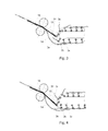
- the apparatus for conveying paper sheets shown in Fig. 1 has an endless conveyor loop 1 of which only a left-hand portion is shown.
- the conveyor loop 1 which may for instance be provided in the form of a belt or a chain, extends along a circulation path and is circulatable in a sense of circulation indicated by arrow 2 along the circulation path.
- a right-hand portion of such a conveyor loop is preferably a loop closing continuation of the portion shown and may for instance extend along a sheet collector for collecting sheets as disclosed in European patent application 2 107 021 .
- a plurality of gripping arms 3 1 -3 11 is located on the outside of the circulation path.
- the gripping arms 3 1 -3 11 are each connected to the loop 1 in positions 4 mutually spaced along the circulation path along which the loop 1 is displaceable.
- the connections 4 are not all designated by reference numerals.
- the gripping arms 3 1 -3 11 are each pivotable between an open position (arms 3 4 -3 8 ) for receiving or releasing a sheet and a closed position (3 1 -3 3 and 3 9 -3 10 ) for retaining an end of the sheet at a gripping position 5.
- the gripping positions 5 are circulatable, in unison with the conveyor loop 1, along a gripping position path 6.
- a paper feeding path constituting a trajectory through which paper sheets 13, 14 can be fed has a downstream end portion 7 oriented towards the gripping position path 6.
- a most downstream transport nip 8 of the paper feeding path is formed between transport rollers 10, 11. This transport nip 8 is located in a position spaced at a distance D grip from the gripping position path 6.
- Upstream of the transport nip 8, a guide 9 bounds the paper transport path 7.
- a prolongation 12 in line with the downstream end portion 7 of the paper feeding path intersects the gripping position path 6.
- a gripping arm operating structure 15 is provided in the form of a cam surface for causing each of the gripping arms 3 1 -3 11 to pivot, relative to a directly adjacent portion of the conveyor loop 1 in the sense of circulation 2 towards the open position prior to passing the prolongation 12 in line with a downstream end portion 7 of the paper feeding path and, subsequently, to pivot, relative to the directly adjacent portion of the conveyor loop 1, contrary to the sense of circulation 2, towards the closed position.
- a lever 16 is fixedly connected to each of the arms 3 1 -3 11 and a cam follower 17 at the free end of the lever is engaged by the cam surface 15.
- a spring member (not shown) is arranged between each of the arms and the loop 1.
- the arms 3 1 -3 11 When passing the prolongation 12 of the downstream end portion 7 of the feeding path, the arms 3 1 -3 11 extend towards the most downstream transport nip 8 of the feeding path up to a distance D arm from the transport nip 8, such that D grip - D arm > 1/4 * D grip .
- D grip - D arm > 1/3 * D grip so that the distance over which the leading ends of sheets are not guided is reduced.
- D grip - D arm 2/3 * D grip so that the distance from the gripping position 5 to which a sheet is to be fed where the leading edge of that sheet passes behind a passing gripping arm is fairly small.
- the arms 3 1 -3 11 each temporarily constitute a guide for guiding a sheet 13 arriving from the transport nip 8 to the gripping position 5 over a substantial distance D grip - D arm .
- the gripping arm operating structure 15 is arranged for starting the pivoting of each gripping arm relative to the directly adjacent portion of the conveyor loop 1 in the sense contrary to the sense of circulation before a next one of the gripping arms passes the prolongation 12 in line with a downstream end portion 7 of the paper feeding path.
- the gripping arm 3 6 has just passed the prolongation 12 in line with a downstream end portion 7 of the paper feeding path and is approximately in its most extreme open position pivoted in circulation sense 2 relative to the directly adjacent portion of the loop 1.
- Fig. 1 the gripping arm 3 6 has just passed the prolongation 12 in line with a downstream end portion 7 of the paper feeding path and is approximately in its most extreme open position pivoted in circulation sense 2 relative to the directly adjacent portion of the loop 1.
- the arm 3 6 has started to pivot back to its closed position in a sense opposite to the sense of circulation 2 as the next gripping arm 3 7 starts to pass the prolongation 12 of the downstream end portion 7 of the paper feeding path.
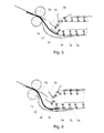
- the gripping arm 3 7 has started to pivot back as the next arm 3 8 starts to pass the prolongation 12
- Fig. 6 it can be seen that the gripping arm 3 8 has started to pivot back as the next arm 3 9 starts to pass the prolongation 12.
- the gripping arm operating structure 15 causes the pivoting of each gripping arm 3 1 -3 11 relative to the directly adjacent portion of the conveyor loop 1 in the sense contrary to the sense of circulation to start relatively early.
- This allows the gripping arms 3 1 -3 11 to be pivoted from the closed position into the open position over a large angle without interfering with a previously fed sheet.
- Figs. 3-8 illustrate that the gripping arms 3 5 and 3 6 are pivoted away from the sheet 14 being fed into an opening between the more downstream arms 3 4 and 3 5 , so that these arms do not hold back the progress of the previously fed sheet 14 to the gripping position 5 between the arms 3 4 and 3 5 .
- Figs. 3-8 illustrate that the gripping arms 3 5 and 3 6 are pivoted away from the sheet 14 being fed into an opening between the more downstream arms 3 4 and 3 5 , so that these arms do not hold back the progress of the previously fed sheet 14 to the gripping position 5 between the arms 3 4 and 3 5 .
- the gap between the gripping arm 3 6 pivoted into the open position and a next gripping arm 3 7 , into which gap the sheet 13 to be entrained is fed can be very large, while the gripping arm 3 6 does not interfere with the previously fed sheet 14 of which a trailing portion is still held in the most downstream nip 8 of the paper feeding path while its leading end is held in or being urged into one of the gripping positions 5 between the arms 3 4 and 3 5 downstream of the gripping position 5 between the arms 3 6 and 3 7 to which the sheet 13 is to be fed.
- Fig. 5 illustrates the same principle for a next sheet 18 being fed into a large opening between arms 3 8 and 3 9 of which the arm 3 8 is in a position pivoted to its most extreme open position.
- the relatively wide opening angle of the gripping arms in the open position allows the sheets 13, 14, 18 to be fed along a path 7 converging with the intended gripping position 5 relatively early, so that a relatively low feeding speed is sufficient to allow the sheets 13, 14, 18 to reach the gripping positions 5. Since the gripping arm 3 5 , 3 7 , 3 9 trailing the leading end of each sheet 13, 14 and respectively 18 pivots back relatively early, in spite of having been pivoted forward over a large angle, the next gripping arm 3 5 , 3 7 , 3 9 does not or only to a minor extent constitute an obstacle that needs to be circumvented by the sheet 13, 14, 18 to reach the gripping position 5.
- the paper feeding path is arranged for feeding the sheets at a constant speed.
- the loop 1 is also circulated at a constant speed, for instance by a suitable drive 19 as schematically shown in Fig. 1 . Feeding the sheets at a constant speed and circulating the loop at a constant speed is advantageous for reducing noise emissions and wear of the apparatus. Moreover, controlling the speed of feeding and, respectively, circulation is simplified so that manufacturing costs can be reduced.
- the speed of feeding the sheets is preferably less than 150% and more preferably less than 130% of the speed of circulation of the loop, so that the extent to which the longest sheets buckle and a curve is formed in the sheets between the most downstream nip of the feeding path and the gripping position is small.
- a large pivoting angle of the gripping arms is advantageous for obtaining a large opening into which sheets can be fed and to allow the leading end of each sheet to be fed relatively early in relation to the passage of the associated gripping position along the intersection with the prolongation of the sheet feeding path. More in particular, to achieve a large advantage using this effect, it is preferred that the gripping arm operating structure is arranged for causing each gripping arm to pivot, relative to the directly adjacent portion of the conveyor loop, over an angle of more than 45° and, more preferably, over an angle of more than 60°.
- the gripping arm operating structure is arranged for pivoting each gripping arm relative to the directly adjacent portion of the conveyor loop in the sense contrary to the sense of circulation immediately after the gripping arm has passed the prolongation in line with a downstream end portion of the paper feeding path.
- the prolongation 12 in line with the downstream end portion 7 of the paper feeding path intersects the gripping position path 6 at an angle larger than 75°.
- the sheets 13, 14, 18 approach the gripping position path quickly while deflection of the leading ends of the sheets 13, 14, 18, which are entrained by gripping arms 3 5 , 3 7 and, respectively 3 9 , in the sense of circulation temporarily adds a velocity component in the direction of the respective gripping position 5 to the movement of the respective leading edge.
- a further advantage of the relatively large openings between successive gripping arms into which the sheets are fed is that reliable feeding of each sheet to an associated gripping position is also possible if the sheets are fed along the paper feeding path in close succession, for instance in a shingled configuration in which each sheet of a series of sheets overlaps a preceding one of the sheets and wherein each sheet is fed in a separate one of spaces between the gripper arms.
- this is illustrated by the sheets 13, 14, 18 being fed in an overlapping configuration in which each next sheets 13, 18 is in a position off-set in upstream direction relative to the position of the previous sheet 14 resp. 13 over a distance smaller than the length of the previous sheet 14 resp. 13.
- This in turn allows sheets to be fed at a high rate without resorting to a high feeding speed which would entail the formation of large buckles as the sheets are transferred from the most downstream feeding nip to the gripping position.
- the gripping arm operating structure may include other means for causing the gripping arms to pivot between the respective closed positions and the open positions, such as trigger pawls acting upon a bi-position spring or magnet controlled gripping arm suspension or solenoids activated in response to contact between a slide contact and a power feeding rail.
- the most downstream transport nip may be a nip between belts or strings or a position where grippers release sheets that are being fed.
- a sheet is fed into each second opening between successive gripping arms. It is however also possible to feed sheets into openings in another pattern, for example by feeding a sheet into each opening or each third opening passing the prolongation of the paper sheet feeding path. It may also be that regularly or irregularly varying numbers of openings are skipped between successive feedings of a sheet into an opening between successive gripping arms.
- the sheets are fed to a curved portion of the gripping position path. It is however also possible to feed the sheets to a straight section of the gripping position path. Since a gripping arm operating structure is provided, it is not necessary to rely on passing the gripping arms through a curved section of the gripping position path for causing openings between successive gripping arms to open for receiving a sheet therein.
Priority Applications (1)
| Application Number | Priority Date | Filing Date | Title |
|---|---|---|---|
| EP10152147A EP2354066A1 (de) | 2010-01-29 | 2010-01-29 | Vorrichtung und Verfahren zum Fördern von Blättern |
Applications Claiming Priority (1)
| Application Number | Priority Date | Filing Date | Title |
|---|---|---|---|
| EP10152147A EP2354066A1 (de) | 2010-01-29 | 2010-01-29 | Vorrichtung und Verfahren zum Fördern von Blättern |
Publications (1)
| Publication Number | Publication Date |
|---|---|
| EP2354066A1 true EP2354066A1 (de) | 2011-08-10 |
Family
ID=42288975
Family Applications (1)
| Application Number | Title | Priority Date | Filing Date |
|---|---|---|---|
| EP10152147A Withdrawn EP2354066A1 (de) | 2010-01-29 | 2010-01-29 | Vorrichtung und Verfahren zum Fördern von Blättern |
Country Status (1)
| Country | Link |
|---|---|
| EP (1) | EP2354066A1 (de) |
Citations (8)
| Publication number | Priority date | Publication date | Assignee | Title |
|---|---|---|---|---|
| US1569256A (en) * | 1923-05-04 | 1926-01-12 | Marinoni Machines Et Materiel | Receiving device for cutting machines of the rotary type for paper or pasteboard, and like machines |
| US3116924A (en) * | 1960-09-23 | 1964-01-07 | William F Huck | Sheet conveying device |
| US3174749A (en) * | 1961-03-16 | 1965-03-23 | Sperry Rand Corp | Sheet stacking device |
| FR2507165A1 (fr) * | 1981-06-04 | 1982-12-10 | Advance Enterprises Inc | Dispositif de transport a grande vitesse pour journaux, magazines et autres |
| FR2514686A1 (fr) * | 1981-10-20 | 1983-04-22 | Rengo Co Ltd | Decoupeuse rotative pour carton ondule dur ou materiaux analogues |
| DE4114095C1 (de) * | 1991-04-30 | 1992-07-30 | Man Roland Druckmaschinen Ag, 6050 Offenbach, De | |
| DE19916668A1 (de) * | 1999-04-14 | 2000-10-26 | Hoerauf Michael Maschf | Vorrichtung zum Transportieren von flach liegenden Zuschnitten |
| EP2107021A1 (de) | 2008-04-03 | 2009-10-07 | Neopost Technologies | Zusammentragen von Postsendungen |
-
2010
- 2010-01-29 EP EP10152147A patent/EP2354066A1/de not_active Withdrawn
Patent Citations (8)
| Publication number | Priority date | Publication date | Assignee | Title |
|---|---|---|---|---|
| US1569256A (en) * | 1923-05-04 | 1926-01-12 | Marinoni Machines Et Materiel | Receiving device for cutting machines of the rotary type for paper or pasteboard, and like machines |
| US3116924A (en) * | 1960-09-23 | 1964-01-07 | William F Huck | Sheet conveying device |
| US3174749A (en) * | 1961-03-16 | 1965-03-23 | Sperry Rand Corp | Sheet stacking device |
| FR2507165A1 (fr) * | 1981-06-04 | 1982-12-10 | Advance Enterprises Inc | Dispositif de transport a grande vitesse pour journaux, magazines et autres |
| FR2514686A1 (fr) * | 1981-10-20 | 1983-04-22 | Rengo Co Ltd | Decoupeuse rotative pour carton ondule dur ou materiaux analogues |
| DE4114095C1 (de) * | 1991-04-30 | 1992-07-30 | Man Roland Druckmaschinen Ag, 6050 Offenbach, De | |
| DE19916668A1 (de) * | 1999-04-14 | 2000-10-26 | Hoerauf Michael Maschf | Vorrichtung zum Transportieren von flach liegenden Zuschnitten |
| EP2107021A1 (de) | 2008-04-03 | 2009-10-07 | Neopost Technologies | Zusammentragen von Postsendungen |
Similar Documents
| Publication | Publication Date | Title |
|---|---|---|
| US6394445B1 (en) | Apparatus for slowing down and guiding a signature and method for doing the same | |
| JPH0561183B2 (de) | ||
| US6302392B1 (en) | Sheet diverter for collating signatures and a method thereof | |
| EP3241790A1 (de) | Bogenstapler | |
| US4550822A (en) | Apparatus for transporting flat products, especially printed products arriving in an imbricated formation | |
| US9346627B2 (en) | Conveyor system and method | |
| EP1795473B1 (de) | Hochgeschwindigkeitsdrehmodul zum Drehen um einen rechten Winkel | |
| JP5175123B2 (ja) | 部分重ね式高速シートコンパイラ | |
| US5819663A (en) | Gripper conveyor with preliminary ink jet | |
| CN117320985A (zh) | 具有多个用于分别加工单张纸的加工站的印刷机 | |
| EP2107021B1 (de) | Vorrichtung zum Zusammentragen von Postsendungen und dazugehöriges Verfahren | |
| US8302954B2 (en) | Sheet feeder for feeding printed sheets to a conveying device | |
| NL1003415C2 (nl) | Werkwijze en inrichting voor het bufferen van papiervellen. | |
| EP2354066A1 (de) | Vorrichtung und Verfahren zum Fördern von Blättern | |
| US7784784B2 (en) | Method and apparatus for transferring printed products conveyed in an shingled flow to a transporter with circulating clamps | |
| US5443256A (en) | Process and device for the formation of a scale-like stream of folded printed copies | |
| US8480084B2 (en) | Conveying device for a gathering section used for further processing of printed products | |
| US8066111B2 (en) | Gripper conveyor delivery | |
| US6736391B1 (en) | Method and apparatus for further conveyance of flat objects arriving in a lamellar flow | |
| EP2003078A1 (de) | Faltvorrichtung | |
| US6773008B2 (en) | Apparatus for transporting sheet-like articles | |
| ATE473938T1 (de) | Bogenanleger zum beschicken einer transportvorrichtung mit gefalzten druckbogen | |
| WO2007021606A2 (en) | Punch with a sheet transport and reorientation mechanism | |
| CA2668746A1 (en) | Conveyor device | |
| CA2437019A1 (en) | Apparatus for transferring products to a conveying arrangement |
Legal Events
| Date | Code | Title | Description |
|---|---|---|---|
| PUAI | Public reference made under article 153(3) epc to a published international application that has entered the european phase |
Free format text: ORIGINAL CODE: 0009012 |
|
| AK | Designated contracting states |
Kind code of ref document: A1 Designated state(s): AT BE BG CH CY CZ DE DK EE ES FI FR GB GR HR HU IE IS IT LI LT LU LV MC MK MT NL NO PL PT RO SE SI SK SM TR |
|
| AX | Request for extension of the european patent |
Extension state: AL BA RS |
|
| STAA | Information on the status of an ep patent application or granted ep patent |
Free format text: STATUS: THE APPLICATION IS DEEMED TO BE WITHDRAWN |
|
| 18D | Application deemed to be withdrawn |
Effective date: 20120211 |