EP2353982A2 - Fuel supply device - Google Patents
Fuel supply device Download PDFInfo
- Publication number
- EP2353982A2 EP2353982A2 EP11151996A EP11151996A EP2353982A2 EP 2353982 A2 EP2353982 A2 EP 2353982A2 EP 11151996 A EP11151996 A EP 11151996A EP 11151996 A EP11151996 A EP 11151996A EP 2353982 A2 EP2353982 A2 EP 2353982A2
- Authority
- EP
- European Patent Office
- Prior art keywords
- fuel
- pressure regulator
- pipe
- disposed
- supply pipe
- Prior art date
- Legal status (The legal status is an assumption and is not a legal conclusion. Google has not performed a legal analysis and makes no representation as to the accuracy of the status listed.)
- Granted
Links
Images


Classifications
-
- B—PERFORMING OPERATIONS; TRANSPORTING
- B62—LAND VEHICLES FOR TRAVELLING OTHERWISE THAN ON RAILS
- B62J—CYCLE SADDLES OR SEATS; AUXILIARY DEVICES OR ACCESSORIES SPECIALLY ADAPTED TO CYCLES AND NOT OTHERWISE PROVIDED FOR, e.g. ARTICLE CARRIERS OR CYCLE PROTECTORS
- B62J37/00—Arrangements of fuel supply lines, taps, or the like, on motor cycles or engine-assisted cycles
-
- F—MECHANICAL ENGINEERING; LIGHTING; HEATING; WEAPONS; BLASTING
- F02—COMBUSTION ENGINES; HOT-GAS OR COMBUSTION-PRODUCT ENGINE PLANTS
- F02D—CONTROLLING COMBUSTION ENGINES
- F02D19/00—Controlling engines characterised by their use of non-liquid fuels, pluralities of fuels, or non-fuel substances added to the combustible mixtures
- F02D19/06—Controlling engines characterised by their use of non-liquid fuels, pluralities of fuels, or non-fuel substances added to the combustible mixtures peculiar to engines working with pluralities of fuels, e.g. alternatively with light and heavy fuel oil, other than engines indifferent to the fuel consumed
- F02D19/0663—Details on the fuel supply system, e.g. tanks, valves, pipes, pumps, rails, injectors or mixers
- F02D19/0665—Tanks, e.g. multiple tanks
-
- F—MECHANICAL ENGINEERING; LIGHTING; HEATING; WEAPONS; BLASTING
- F02—COMBUSTION ENGINES; HOT-GAS OR COMBUSTION-PRODUCT ENGINE PLANTS
- F02D—CONTROLLING COMBUSTION ENGINES
- F02D19/00—Controlling engines characterised by their use of non-liquid fuels, pluralities of fuels, or non-fuel substances added to the combustible mixtures
- F02D19/06—Controlling engines characterised by their use of non-liquid fuels, pluralities of fuels, or non-fuel substances added to the combustible mixtures peculiar to engines working with pluralities of fuels, e.g. alternatively with light and heavy fuel oil, other than engines indifferent to the fuel consumed
- F02D19/0663—Details on the fuel supply system, e.g. tanks, valves, pipes, pumps, rails, injectors or mixers
- F02D19/0673—Valves; Pressure or flow regulators; Mixers
- F02D19/0678—Pressure or flow regulators therefor; Fuel metering valves therefor
-
- F—MECHANICAL ENGINEERING; LIGHTING; HEATING; WEAPONS; BLASTING
- F02—COMBUSTION ENGINES; HOT-GAS OR COMBUSTION-PRODUCT ENGINE PLANTS
- F02D—CONTROLLING COMBUSTION ENGINES
- F02D19/00—Controlling engines characterised by their use of non-liquid fuels, pluralities of fuels, or non-fuel substances added to the combustible mixtures
- F02D19/06—Controlling engines characterised by their use of non-liquid fuels, pluralities of fuels, or non-fuel substances added to the combustible mixtures peculiar to engines working with pluralities of fuels, e.g. alternatively with light and heavy fuel oil, other than engines indifferent to the fuel consumed
- F02D19/0663—Details on the fuel supply system, e.g. tanks, valves, pipes, pumps, rails, injectors or mixers
- F02D19/0697—Arrangement of fuel supply systems on engines or vehicle bodies; Components of the fuel supply system being combined with another device
-
- F—MECHANICAL ENGINEERING; LIGHTING; HEATING; WEAPONS; BLASTING
- F02—COMBUSTION ENGINES; HOT-GAS OR COMBUSTION-PRODUCT ENGINE PLANTS
- F02D—CONTROLLING COMBUSTION ENGINES
- F02D19/00—Controlling engines characterised by their use of non-liquid fuels, pluralities of fuels, or non-fuel substances added to the combustible mixtures
- F02D19/06—Controlling engines characterised by their use of non-liquid fuels, pluralities of fuels, or non-fuel substances added to the combustible mixtures peculiar to engines working with pluralities of fuels, e.g. alternatively with light and heavy fuel oil, other than engines indifferent to the fuel consumed
- F02D19/08—Controlling engines characterised by their use of non-liquid fuels, pluralities of fuels, or non-fuel substances added to the combustible mixtures peculiar to engines working with pluralities of fuels, e.g. alternatively with light and heavy fuel oil, other than engines indifferent to the fuel consumed simultaneously using pluralities of fuels
- F02D19/082—Premixed fuels, i.e. emulsions or blends
- F02D19/084—Blends of gasoline and alcohols, e.g. E85
-
- F—MECHANICAL ENGINEERING; LIGHTING; HEATING; WEAPONS; BLASTING
- F02—COMBUSTION ENGINES; HOT-GAS OR COMBUSTION-PRODUCT ENGINE PLANTS
- F02M—SUPPLYING COMBUSTION ENGINES IN GENERAL WITH COMBUSTIBLE MIXTURES OR CONSTITUENTS THEREOF
- F02M37/00—Apparatus or systems for feeding liquid fuel from storage containers to carburettors or fuel-injection apparatus; Arrangements for purifying liquid fuel specially adapted for, or arranged on, internal-combustion engines
- F02M37/0011—Constructional details; Manufacturing or assembly of elements of fuel systems; Materials therefor
- F02M37/0023—Valves in the fuel supply and return system
- F02M37/0029—Pressure regulator in the low pressure fuel system
-
- F—MECHANICAL ENGINEERING; LIGHTING; HEATING; WEAPONS; BLASTING
- F02—COMBUSTION ENGINES; HOT-GAS OR COMBUSTION-PRODUCT ENGINE PLANTS
- F02M—SUPPLYING COMBUSTION ENGINES IN GENERAL WITH COMBUSTIBLE MIXTURES OR CONSTITUENTS THEREOF
- F02M37/00—Apparatus or systems for feeding liquid fuel from storage containers to carburettors or fuel-injection apparatus; Arrangements for purifying liquid fuel specially adapted for, or arranged on, internal-combustion engines
- F02M37/0047—Layout or arrangement of systems for feeding fuel
- F02M37/0064—Layout or arrangement of systems for feeding fuel for engines being fed with multiple fuels or fuels having special properties, e.g. bio-fuels; varying the fuel composition
-
- F—MECHANICAL ENGINEERING; LIGHTING; HEATING; WEAPONS; BLASTING
- F02—COMBUSTION ENGINES; HOT-GAS OR COMBUSTION-PRODUCT ENGINE PLANTS
- F02M—SUPPLYING COMBUSTION ENGINES IN GENERAL WITH COMBUSTIBLE MIXTURES OR CONSTITUENTS THEREOF
- F02M37/00—Apparatus or systems for feeding liquid fuel from storage containers to carburettors or fuel-injection apparatus; Arrangements for purifying liquid fuel specially adapted for, or arranged on, internal-combustion engines
- F02M37/0047—Layout or arrangement of systems for feeding fuel
- F02M37/007—Layout or arrangement of systems for feeding fuel characterised by its use in vehicles, in stationary plants or in small engines, e.g. hand held tools
-
- F—MECHANICAL ENGINEERING; LIGHTING; HEATING; WEAPONS; BLASTING
- F02—COMBUSTION ENGINES; HOT-GAS OR COMBUSTION-PRODUCT ENGINE PLANTS
- F02M—SUPPLYING COMBUSTION ENGINES IN GENERAL WITH COMBUSTIBLE MIXTURES OR CONSTITUENTS THEREOF
- F02M37/00—Apparatus or systems for feeding liquid fuel from storage containers to carburettors or fuel-injection apparatus; Arrangements for purifying liquid fuel specially adapted for, or arranged on, internal-combustion engines
- F02M37/22—Arrangements for purifying liquid fuel specially adapted for, or arranged on, internal-combustion engines, e.g. arrangements in the feeding system
- F02M37/32—Arrangements for purifying liquid fuel specially adapted for, or arranged on, internal-combustion engines, e.g. arrangements in the feeding system characterised by filters or filter arrangements
- F02M37/44—Filters structurally associated with pumps
-
- F—MECHANICAL ENGINEERING; LIGHTING; HEATING; WEAPONS; BLASTING
- F02—COMBUSTION ENGINES; HOT-GAS OR COMBUSTION-PRODUCT ENGINE PLANTS
- F02M—SUPPLYING COMBUSTION ENGINES IN GENERAL WITH COMBUSTIBLE MIXTURES OR CONSTITUENTS THEREOF
- F02M37/00—Apparatus or systems for feeding liquid fuel from storage containers to carburettors or fuel-injection apparatus; Arrangements for purifying liquid fuel specially adapted for, or arranged on, internal-combustion engines
- F02M37/22—Arrangements for purifying liquid fuel specially adapted for, or arranged on, internal-combustion engines, e.g. arrangements in the feeding system
- F02M37/32—Arrangements for purifying liquid fuel specially adapted for, or arranged on, internal-combustion engines, e.g. arrangements in the feeding system characterised by filters or filter arrangements
- F02M37/50—Filters arranged in or on fuel tanks
-
- F—MECHANICAL ENGINEERING; LIGHTING; HEATING; WEAPONS; BLASTING
- F02—COMBUSTION ENGINES; HOT-GAS OR COMBUSTION-PRODUCT ENGINE PLANTS
- F02M—SUPPLYING COMBUSTION ENGINES IN GENERAL WITH COMBUSTIBLE MIXTURES OR CONSTITUENTS THEREOF
- F02M69/00—Low-pressure fuel-injection apparatus ; Apparatus with both continuous and intermittent injection; Apparatus injecting different types of fuel
- F02M69/04—Injectors peculiar thereto
- F02M69/042—Positioning of injectors with respect to engine, e.g. in the air intake conduit
- F02M69/044—Positioning of injectors with respect to engine, e.g. in the air intake conduit for injecting into the intake conduit downstream of an air throttle valve
-
- B—PERFORMING OPERATIONS; TRANSPORTING
- B62—LAND VEHICLES FOR TRAVELLING OTHERWISE THAN ON RAILS
- B62K—CYCLES; CYCLE FRAMES; CYCLE STEERING DEVICES; RIDER-OPERATED TERMINAL CONTROLS SPECIALLY ADAPTED FOR CYCLES; CYCLE AXLE SUSPENSIONS; CYCLE SIDE-CARS, FORECARS, OR THE LIKE
- B62K2202/00—Motorised scooters
-
- F—MECHANICAL ENGINEERING; LIGHTING; HEATING; WEAPONS; BLASTING
- F02—COMBUSTION ENGINES; HOT-GAS OR COMBUSTION-PRODUCT ENGINE PLANTS
- F02B—INTERNAL-COMBUSTION PISTON ENGINES; COMBUSTION ENGINES IN GENERAL
- F02B61/00—Adaptations of engines for driving vehicles or for driving propellers; Combinations of engines with gearing
- F02B61/02—Adaptations of engines for driving vehicles or for driving propellers; Combinations of engines with gearing for driving cycles
-
- F—MECHANICAL ENGINEERING; LIGHTING; HEATING; WEAPONS; BLASTING
- F02—COMBUSTION ENGINES; HOT-GAS OR COMBUSTION-PRODUCT ENGINE PLANTS
- F02M—SUPPLYING COMBUSTION ENGINES IN GENERAL WITH COMBUSTIBLE MIXTURES OR CONSTITUENTS THEREOF
- F02M2200/00—Details of fuel-injection apparatus, not otherwise provided for
- F02M2200/95—Fuel injection apparatus operating on particular fuels, e.g. biodiesel, ethanol, mixed fuels
-
- Y—GENERAL TAGGING OF NEW TECHNOLOGICAL DEVELOPMENTS; GENERAL TAGGING OF CROSS-SECTIONAL TECHNOLOGIES SPANNING OVER SEVERAL SECTIONS OF THE IPC; TECHNICAL SUBJECTS COVERED BY FORMER USPC CROSS-REFERENCE ART COLLECTIONS [XRACs] AND DIGESTS
- Y02—TECHNOLOGIES OR APPLICATIONS FOR MITIGATION OR ADAPTATION AGAINST CLIMATE CHANGE
- Y02T—CLIMATE CHANGE MITIGATION TECHNOLOGIES RELATED TO TRANSPORTATION
- Y02T10/00—Road transport of goods or passengers
- Y02T10/10—Internal combustion engine [ICE] based vehicles
- Y02T10/30—Use of alternative fuels, e.g. biofuels
Definitions
- the present invention relates to an improvement in a fuel supply device of a motorcycle.
- a fuel pump 81 is provided inside a fuel tank 33, a fuel filter 83 is connected to the fuel pump 81 via a supply pipe 82, a fuel pressure regulator 85 is connected to the fuel filter 83 via a fuel hose 84, a fuel injector 50 is connected to the fuel pressure regulator 85 via a connection pipe 86, and a return hose 87 is connected from the fuel pressure regulator 85 to a bottom of the fuel tank 33.
- An object of the present invention is to provide a fuel supply device that allows these fuel pipes to be bent with a larger radius.
- a storage box is provided below a seat of a motorcycle and a fuel tank is provided behind the storage box, an air-intake device and a fuel injection device for an engine is disposed behind the storage box, fuel in the fuel tank being press-fed into the fuel injection device by a fuel pump disposed inside the fuel tank, a pressure regulator is disposed at a midpoint of fuel supply piping interconnecting the fuel pump and the fuel injection device, fuel is supplied from the fuel pump to the pressure regulator via a first supply pipe constituting the fuel supply piping, fuel being supplied from the pressure regulator to the fuel injection device via a second supply pipe constituting the fuel supply piping and excess fuel being returned from the pressure regulator to the fuel tank via a return pipe, and wherein the pressure regulator is disposed in front of the storage box; the first supply pipe and the return pipe are disposed on one side and another side of the storage box via the pressure regulator; and the first supply pipe and the return pipe are disposed so as to form a U shape.
- the first supply pipe and the return pipe are connected to one side and the other side respectively, across the vehicle body, of the pressure regulator.
- the engine is provided with a cylinder portion projecting forward horizontally, the pressure regulator is disposed above a crankcase of the engine and behind the fuel injection device, and the second supply pipe is disposed along a vehicle body frame extending in a longitudinal direction.
- the vehicle body frame is provided with one main frame extending obliquely downward and rearward from a head pipe and a seat frame bifurcated left and right from the main frame in front of the storage box; the pressure regulator is disposed between the left and right seat frames in a plain view; and a rear end of the second supply pipe is connected to a front side joint portion provided on the pressure regulator and extends in a curve from one of left and right edges of the main frame over the main frame to downward of the main frame above a cylinder portion and within the left and right width of the cylinder portion so that the front end of the second supply pipe is connected to the fuel injection device.
- a rear wheel of the motorcycle is attached to a rear end of a swing arm supported by the vehicle body frame swingably up and down; and a fuel filter disposed at a midpoint of the first supply pipe is disposed within a swingable range of the rear wheel in a side view.
- the first supply pipe, the return pipe, the fuel filter, and the pressure regulator are disposed inside the vehicle body frame in the plain view; and a leg shield covering the legs of an occupant sitting on the seat from the front covers the second supply pipe at a rear of the center portion thereof.
- fuel contains ethanol
- ethanol concentration in fuel is determined from components of an exhaust gas from the engine, and control of fuel injection by the fuel injection device is switched according to the ethanol concentration; and the second supply pipe is made of a rubber hose.
- the first supply pipe and the return pipe are made of a resin hose.
- the fuel pump is provided with a fuel discharge joint passing through a flange that closes an opening in a top surface of the fuel tank and bends toward one side in a vehicle width direction; and the first supply pipe is connected to the fuel discharge joint from one side in the vehicle width direction.
- the seat is of a tandem type having front and back seating portions for allowing two persons to sit thereon; and a stepped portion is formed between the front and back seating portions and the fuel discharge joint is provided below the stepped portion.
- the pressure regulator is disposed in front of the storage box, the first supply pipe and the return pipe are disposed at one side and the other side of the storage box via the pressure regulator, and the first supply pipe and the return pipe are arranged so as to form a U shape. Since the first supply pipe and the return pipe are arranged in the U shape, it is possible to make a curve formed by the first supply pipe and the return pipe gentle with a simple construction and thereby to prevent stress concentration.
- the first supply pipe and the return pipe are connected respectively to one side and the other side in the vehicle width direction, of the pressure regulator, it is possible to shorten the curved portions of the first supply pipe and the return pipe by reducing the curved portions, and thereby to make it easer to dispose the first supply pipe and the return pipe and also reduce the cost thereof.
- the pressure regulator is disposed above the crankcase of the engine and behind the fuel injection device, and the second supply pipe is disposed along the vehicle body frame extending forward and backward, it is possible to protect the pressure regulator with the crankcase of the engine and also to protect the second supply pipe with the vehicle body frame.
- the engine has the horizontal cylinder portion, it is possible to make a lateral distance between the pressure regulator and the fuel injection device longer as compared to, for example, an engine whose cylinder portion extends upward from the crankcase.
- the vehicle body frame includes: one main frame extending obliquely downward behind the head pipe; and a seat frame bifurcating left and right from the main frame in front of the storage box, and wherein: the pressure regulator is disposed between the left and right seat frames in a plain view; and the second supply pipe is connected to, at a rear end thereof, a front side joint portion provided on the pressure regulator, and extends downward in a curve above the main frame from one of left and right edges of the main frame, above the cylinder portion and within the lateral width of the cylinder portion and then a front edge thereof is connected to the fuel injection device.
- This allows the second supply pipe to be protected with the vehicle body frame and the cylinder portion.
- the rear wheel of the motorcycle is attached to a rear end of the swing arm that is vertically swingably supported by the vehicle body frame, and the fuel filter disposed at a midpoint of the first supply pipe is disposed within a swingable range of the rear wheel in a side view, it is possible to easily prevent an interference between the fuel filter and the rear wheel by disposing the fuel filter on one side in the vehicle width direction.
- the first supply pipe, the return pipe, the fuel filter, and the pressure regulator are disposed inside the vehicle body frame in the plain view, and a leg shield covering legs of an occupant sitting on the seat from the front thereof covers the second supply pipe at an end of the center of the leg shield, it is possible to protect the first supply pipe, the return pipe, the fuel filter, and the pressure regulator with the vehicle body frame, thus allowing the appearance to be improved by covering the pressure regulator with the leg shield. Also, a special cover member to cover the pressure regulator is not necessary and thus the number of components can be reduced.
- the fuel contains ethanol
- ethanol concentration in the fuel can be determined by a control device from components of exhaust gas from the engine
- fuel injection control by the fuel injection device is switched based on the ethanol concentration
- the second supply pipe is made of a rubber hose, it is possible to suppress a pulsation of the fuel fed to the fuel injection device by employing a flexible rubber hose for the second supply pipe, thus allowing combustion of the engine to be stabilized.
- switching of the fuel injection control by the fuel injection device based on ethanol concentration by the control device enables appropriate control of engine combustion and enhancement of engine performance.
- first supply pipe and the return pipe are each made of a resin hose, outer diameters of the first supply pipe and the return pipe can be reduced, a piping work can be facilitated particularly for a small vehicle with a small body space, and also it is possible to reduce the cost than for rubber hoses.
- the fuel pump is provided with the fuel discharge joint passing through the flange which closes an opening in the top surface of the fuel tank and bends toward one side in the vehicle width direction, and the first supply pipe is connected to the fuel discharge joint from one side in the vehicle width direction, it is possible to easily dispose the first supply pipe on one side in the vehicle width direction.
- the seat is of the tandem type having front and rear seat portions that enables the seating of two persons, the stepped portion is formed between the front and rear seat portions, and the fuel discharge joint is provided below the stepped portion, it is possible to secure a seat thickness even if the fuel discharge joint projecting upward is provided. Therefore, a comfortable ride can be maintained.
- a motorcycle 10 includes a vehicle body frame 11 as a skeleton, and the vehicle body frame 11 is composed of a head pipe 12 composing a front end portion; one main frame 13 obliquely extending downward and rearward from the head pipe 12; a pair of left and right rear frames 14, 16 (only the near reference sign 14 is shown) extending obliquely upward and rearward respectively from left and right of a center portion of the main frame 13; and a pair of left and right pivot plates 17, 18 (only the near reference sign 17 is shown) attached to an rear end portion of the main frame 13.
- the rear frames 14, 16 are also attached to the pivot plates 17, 18 and provided with a rear-end extending portion 19 provided substantially horizontally to a rear end portion.
- a front fork 21 is steerably attached to the head pipe 12, a front wheel 22 is attached to a lower end of the front fork 21 and a handlebar 23 is attached to an upper end thereof.
- An upper portion of an engine 25 is attached to a rear portion of the main frame 13 and an air cleaner 26 is attached to a front portion thereof.
- the rear frames 14, 16 support a lower portion of a storage box 27 at front and center portions thereof, and support a rear end of the storage box 27 and a fuel tank 28 at a rear portion, specifically at the rear-end extending portion 19 thereof.
- a rear end portion of the engine 25 is attached to front portions of the pivot plates 17, 18, and a swing arm 32 is attached swingably up and down to a center portion thereof via a pivot axis 31.
- a rear wheel 33 is attached to a rear end portion of the swing arm 32. The rear wheel 33 can be shifted up to a position indicated by a dashed two-dot line by swinging upward the swing arm 32.
- the engine 25 is composed of a crankcase 41 and a cylinder portion 42 attached to a front end portion of the crankcase 41 so as to extend forward, and the crankcase 41 has a transmission inside it.
- the cylinder portion 42 is composed of a cylinder block 44 attached to the crankcase 41, a cylinder head 45 attached to the cylinder block 44, and a head cover 46 covering an opening of the cylinder head 45.
- the cylinder head 45 has an air-intake device 47 connected to an upper portion thereof and an air-exhaust device 48 connected to a lower portion thereof.
- the air-intake device 47 is composed of an intake pipe 51 connected to an upper portion of the cylinder head 45, a throttle body 52 connected to the intake pipe 51, and the air cleaner 26 connected to the throttle body 52 via a connecting tube 53.
- a fuel supply device 54 which feeds ethanol-mixed fuel containing ethanol from the fuel tank 28 to the engine 25, is connected to the throttle body 52.
- the air-exhaust device 48 comprises an exhaust pipe 57 connected to a lower portion of the cylinder head 45 and a muffler 58 connected to a rear end of the exhaust pipe 57.
- an engine control unit 60 that controls the ignition timing of the engine 25, the amount of fuel injected from an injector 102 to be described later, fuel injecting timing, and the like.
- the ECU 60 determines ethanol concentration in fuel based on a signal from an O 2 sensor (not shown) that detects oxygen in an exhaust gas from the engine 25, and according to the ethanol concentration, switches control of fuel injection from the injector 102.
- sign 61 designates a head lamp, 62 a handlebar cover, 63 a front cover, 64 a leg shield, 66 a front fender, 67 a seat, 68 an occupant's helmet, 71 a rear cover, 72 a tail lamp, 73 a rear fender, and 74 a rear cushion unit.
- the rear frames 14, 16 (only near reference sign 14 is shown) is composed of a cross member 81 located at the front portion thereof, having a recessed cross-section and extending in the vehicle width direction, a first cross pipe 83 located at the center portion thereof, specifically at bent portions 14a, 16a (only the near reference sign 14a is shown), and extending in the vehicle width direction, and a second cross pipe 84 located at the rear portion thereof and extending in the vehicle width direction.
- the cross member 81 supports a bottom portion of the storage box 27 (refer to Fig. 1 ), and rear end portions of the left and right pivot plates 17, 18 (only the near reference sign 17 is shown) are attached to the first cross pipe 83. Accordingly, the rear frames 14, 16 and the pivot plates 17, 18 are connected via the first cross pipe 83.
- the rear frames 14, 16 have a pair of left and right nuts 85, 85 (only the near reference sign 85 is shown) and nuts 86, 86 (only one reference sign 86 is shown) installed at front and rear end portions of the rear-end extending portion 19, and the storage box 27 and the fuel tank 28 (refer to Fig. 1 ) are attached to the rear-end extending portion 19 with the nuts 85, 86 and unshown bolts.
- the fuel supply device 54 includes: the fuel tank 28; a fuel pump 91 mounted on a top of the fuel tank 28; a primary fuel filter 93 attached to the fuel pump 91; a secondary fuel filter 96 connected to the fuel pump 91 attached with the primary fuel filter 93 via a fuel pipe 94; the pressure regulator 98 connected to the secondary fuel filter 96 via a fuel pipe 97; the injector 102 connected to the pressure regulator 98 via a fuel pipe (a secondary supply pipe) 101; and the return pipe 118 (refer to Fig. 6 ) connecting the pressure regulator 98 and the fuel tank 28, and the injector 102 is attached to the throttle body 52 (refer to Fig. 1 ) of the air-intake device 47 (refer to Fig. 1 ).
- fuel supply piping 103 is formed that feeds fuel from the fuel tank 28 to the throttle body 52 on the side of the engine 25 (refer to Fig. 1 ).
- the fuel supply piping 103 is composed of fuel pipes 94, 97, and 101, of which the fuel pipes 94 and 97 constitute a fuel pipe (a first supply pipe) 106 from the fuel pump 91 to the pressure regulator 98.
- the storage box 27 is formed so large that a full-face type helmet 68 can be stored therein.
- reference sign 27a is a seat-mounting portion provided at a front end portion of the storage box 27 in order to raisably mount the seat 67 on the storage box 27.
- the seat 67 is of the tandem type composed of a rider seat 67a on which a rider seats, and a pillion passenger seat 67b that is formed behind the rider seat 67a at a position one step higher than the rider seat for a pillion passenger to seat.
- a stepped portion 67c is formed between the rider seat 67a and the pillion passenger seat 67b, and an upper end of the fuel pump 91 is disposed below the stepped portion 67c.
- the fuel pump 91 is provided with, at the top thereof, a fuel discharge portion 104 projecting upward, and the fuel pipe 94 is connected to the fuel discharge portion 104.
- the secondary fuel filter 96 is removably attached to an upper surface of the rear fender 73, and is disposed between the storage box 27 and the rear fender 73 and between the left and right rear frames 14, 16 (only the near reference sign 14 is shown).
- the pressure regulator 98 is removably held by a regulator bracket 105 attached to a front portion of the cross member 81, and is disposed in front of the storage box 27 and above the main frame 13, above front portions of the rear frames 14, 16, and above the cross member 81 in a side view.
- a pair of left and right upper mounting portions 27d, 27e (only the near reference sign 27d is shown) that projects rearward so as to be attached to the rear-end extending portion 19; an upper vertical wall portion 27f extending downward from these upper mounting portions 27d, 27e; an upper oblique wall portion 27g extending forward diagonally downward from a lower end of the upper vertical wall portion 27f; a lower vertical wall portion 27j extending downward from the upper oblique wall portion 27g; and a lower support portion 27k extending forward from the lower vertical wall portion 27j so as to be supported by the first cross pipe 83 via a rubber 107.
- the upper vertical wall portion 27f, the upper oblique wall portion 27g, and the lower vertical wall portion 27j of the above-mentioned rear wall 27c are, as a whole, inclined so that the upper vertical wall portion 27f is positioned behind the lower vertical wall portion 27j.
- the rear fender 73 projects upward in a projecting manner so as to form an arc in order to cover front, upper, and rear portions of the rear wheel 33 (refer to Fig. 1 ), is composed of a front portion 73a and a rear portion 73b which are formed at the front and rear with a peak of the arc as a boundary, and has a projecting portion 73c formed in the projecting manner radially outward so as to prevent the interference with the rear wheel 33 over the front portion 73a and the rear portion 73b.
- the front portion 73a of the rear fender 73 is disposed so as to face the rear wall 27c of the storage box 27, and is formed so as to gradually separate rearward from the rear wall 27c up to its upper end. Consequently, a space 108 formed between the rear wall 27c of the storage box 27 and the front portion 73a of the rear fender 73 gradually increases in the longitudinal direction up to an upper end of the space 108.
- a recessed portion 73d recessed toward the rear wheel 33 side is formed at a position facing the rear wall 27c of the storage box 27, specifically the upper inclined wall 27g, and a part of the secondary fuel filter 96 is accommodated in the recessed portion 73d.
- the secondary fuel filter 96 is removably held at a bottom 73e of the recessed portion 73d via an integrally or separately provided holder 111, and is disposed so as to incline forward and downward along the rear inclined portions 14c, 16c of the rear frames 14, 16 and the projecting portion 73c of the rear fender 73.
- reference signs 115, 116 are connecting assemblies provided at respective end portions of the fuel pipes 94, 97 and connected to the secondary fuel filter 96.
- the holder 111 is composed of a pair of holding members 112, 112 (only the near reference sign 112 is shown) projecting from a bottom portion 73a thereof; and a rubber fastening member 113 having holes formed to press-fit to the holding members 112, 112, and the fastening member 113 is fit into an outer peripheral portion of the secondary fuel filter 96.
- reference sign 73g designates a front locking portion provided at the center in the vehicle width direction of a front portion of the rear fender 73.
- the secondary fuel filter 96 is disposed along the rear inclined portions 14c, 16c of the rear frames 14, 16 and the projecting portion 73c of the rear fender 73 in a longitudinal direction.
- the fuel supply device 54 has the return pipe 118, one end of which is connected to the pressure regulator 98 and the other end of which is connected to a return port 28b provided at the bottom portion 28a of the fuel tank 28.
- the secondary fuel filter 96 is disposed to the left of the projecting portion 73c of the rear fender 73 and between the rear frames 14 and 16, i.e., between the projecting portion 73c and the one rear frame 14.
- the secondary fuel filter 96 is disposed between and along the projecting portion 73c and the rear frame 14, it is possible to easily dispose it even if the space 121 is small, and thereby to utilize the space 121 more effectively.
- the upper mounting portions 27d, 27e of the storage box 27 and the flange portion 28d of the fuel tank 28 are jointly fastened to both front ends of the rear-end extending portion 19 of the rear frames 14, 16 via a mount rubber 123 provided between the upper mounting portions 27d, 27e and the flange portion 28d.
- a bolt 124 penetrates through the upper mounting portion 27d, the mount rubber 123, the flange portion 28d, and the rear-end extending portion 19 and is screwed into a nut 125 provided in the rear-end extending portion 19.
- the flange portion 28d, the mount rubber 123, and the upper mounting portion 27e of the storage box 27 are mounted in this order on the rear-end extending portion 19 of the rear frames 14, 16, and the bolt 124 penetrates through the upper mounting portion 27e, the rubber 123, the flange portion 28d and the rear-end extending portion 19, and is screwed into the nut 125 provided in the rear-end extending portion 19.
- the fuel pump 91 is provided with a flange 127 at its upper portion and the flange 127 is attached to a top surface of the fuel tank 28.
- the flange 127 is provided with the fuel discharge portion 104 that passes through the flange 127, projects upward, and extends to the left side of the vehicle body.
- the fuel pipe 97 constituting the fuel supply device 54 is disposed above the rear frame 14, extending from the secondary fuel filter 96 to the pressure regulator 98 along the rear frame 14, and the return pipe 118 is disposed above the rear frame 16, extending from the pressure regulator 98 to a lower portion of the fuel tank 28 along the other rear frame 16.
- the secondary fuel filter 96 is composed of a filter case 131 and a filter assembly 132 housed inside the filter case 131, and pores of the filter assembly 132 are made finer than those of the primary fuel filter 93 (refer to Fig. 4 ) .
- the filter case 131 is composed of a bottomed tubular case body 134 and a case cover 136 to close an opening portion of the case body 134.
- the case body 134 is provided with a fuel suction port 134a that is connected to the fuel pipe 94 (refer to Fig. 5 ) on the fuel tank 28 (refer to Fig. 5 ) side for sucking fuel
- the case cover 136 is provide with a fuel discharge port 136a that is connected to the fuel pipe 97 (refer to Fig. 5 ) on the injector 102 (refer to Fig. 3 ) side for discharging fuel.
- the filter assembly 132 is composed of a tubular filter 141 made of a filter paper and frames 142, 143 supporting both ends of the filter 141, and is fixed by sandwiching it between the case body 134 and the case cover 136.
- Fuel is sucked into the filter case 131 from the fuel suction port 134a, filtered while flowing to pass from an outer peripheral surface 141a of the filter 141 to an inner peripheral surface 141b thereof, and then discharged outside the filter case 131 through the fuel discharge port 136a.
- the pressure regulator 98 is composed of a case 161 with a resin first case 161E and a resin second case 161F joined together; a spherical steel valve element 162 which opens and closes a through-hole 161a opened in a bottom of one end of the case 161; a compression coil spring 163 that presses the valve element 162 to close the through-hole 161a; a fuel suction port 165 in which the through-hole 161a is opened; a fuel discharge port 166 formed at a midpoint of the fuel suction port 165; and a fuel return port 167 having a through-hole 161c that is opened in a bottom of the other end of the case 161.
- the fuel suction port 165 is connected to the secondary fuel filter 96 (refer to Fig. 6 ), the fuel discharge port 166 is connected to the injector 102 (refer to Fig. 3 ), and the fuel return port 167 is connected to the fuel tank 28 (refer to Fig 6 ).
- the air-intake device 47 and the injector 102 as a fuel injection device for the engine 25 being disposed in front of the storage box 27, fuel in the fuel tank 28 being press-fed into the injector 102 by the fuel pump 91 disposed inside the fuel tank 28, the pressure regulator 98 being disposed at a midpoint of the fuel supply piping 103 interconnecting the fuel pump 91 and the injector 102, fuel being supplied from the fuel pump 91 to the pressure regulator 98 via the fuel pipe 106 as a first supply pipe, fuel being supplied from the pressure regulator 98 to the injector 102 via the fuel pipe 101 as a second supply pipe, and extra fuel being returned from the pressure regulator 98 to the fuel tank 28 via the return pipe 118, wherein the fuel pipe 106 and the return pipe 118 are arranged in a U shape by placing the pressure regulator 98
- the pressure regulator 98 since the fuel pipe 106 and the return pipe 118 are connected to one side and the other side in the vehicle width direction respectively, it is possible to shorten the fuel pipe 106 and the return pipe 118 by reducing bent portions, and also to easily dispose the fuel pipe 106 and the return pipe 118 and reduce a cost thereof.
- the pressure regulator 98 is disposed above the crankcase 41 of the engine 25 and behind the injector 102, and the fuel pipe 101 as secondary supply piping is disposed along the vehicle body frame 11, specifically the main frame 13, extending in a longitudinal direction, it is possible to protect the pressure regulator 98 with the crankcase 41 of the engine 25 and also to protect the fuel pipe 101 with the main frame 13.
- a distance between the pressure regulator 98 and the injector 102 can be made longer in a longitudinal direction than, for example, an engine whose cylinder portion extends upward from a crankcase.
- the pressure regulator 98 is disposed between the left and right rear frames 14, 16 in a plain view, and the fuel pipe 101 is connected, at the rear end thereof, to the fuel discharge port 166 as a front side joint portion provided on the pressure regulator 98, extends while curving over the main frame 13 from one of the left and right edges of the main frame 13 to downward of the main frame 13 above the cylinder portion 42 and within the width of it, and is connected, at a front end thereof, to the injector 102, it is possible to protect the fuel pipe 101 with the main frame 13 and the cylinder portion 42.
- the fuel contains ethanol and ethanol concentration in the fuel is determined from components of the exhaust gas from the engine 25 by means of the ECU 60 as a control device
- the fuel injection control by the injector 102 is switched according to the ethanol concentration
- the fuel pipe 101 is made of a rubber hose, it is possible to suppress the pulsation of fuel fed into the injector 102 and thereby stabilize the combustion of the engine 25 by employing the flexible rubber hose for the fuel pipe 101.
- the fuel injection control by the injector 102 is switched by the ECU 60 according to ethanol concentration, it is possible to appropriately control the combustion of the engine 25 and thereby improve engine performance.
- the fuel pipe 106 and the return pipe 118 are made of the resin hose, the outer diameters of the fuel pipe 106 and the return pipe 118 can be reduced, and it is possible to make a piping work easier especially for a small vehicle with a small body space and also reduce the cost as compared to a rubber hose.
- the fuel pump 91 is provided with the fuel discharge port 104 as a fuel discharge joint passing through the flange 127 closing an opening in the top of the fuel tank 28 and bending to one side in the vehicle with direction, and the fuel pipe 106 is connected to the fuel discharge port 104 from one side in the vehicle width direction, it is possible to make it easier to dispose the fuel pipe 106 on one side in the vehicle width direction.
- the seat 67 is of the tandem type having the rider seat 67a at the front and the pillion passenger seat 67b at the rear to allow two persons to seat, the stepped portion 67c is formed between the rider seat 67a and the pillion passenger seat 67b, and the fuel discharge port 104 is provided below the stepped portion 67c, it is possible to secure a seat thickness even if the fuel discharge port 104 projecting upward is provided, thus allowing a comfortable ride to be maintained.
- a fuel supply device of the present invention is preferable for a motorcycle.
Landscapes
- Engineering & Computer Science (AREA)
- Chemical & Material Sciences (AREA)
- Mechanical Engineering (AREA)
- Combustion & Propulsion (AREA)
- General Engineering & Computer Science (AREA)
- Oil, Petroleum & Natural Gas (AREA)
- Automatic Cycles, And Cycles In General (AREA)
- Fuel-Injection Apparatus (AREA)
- Combined Controls Of Internal Combustion Engines (AREA)
Abstract
Description
- The present invention relates to an improvement in a fuel supply device of a motorcycle.
- As a conventional fuel supply device, there is known a device in which a plurality of fuel pipes interconnect a fuel tank side and a fuel injector side which injects and supplies fuel into an engine (for example, refer to Patent Literature 1).
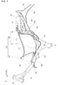
- 1 According to
Figs. 2 and3 in Patent Literature 1, afuel pump 81 is provided inside afuel tank 33, afuel filter 83 is connected to thefuel pump 81 via a supply pipe 82, afuel pressure regulator 85 is connected to thefuel filter 83 via afuel hose 84, a fuel injector 50 is connected to thefuel pressure regulator 85 via aconnection pipe 86, and a return hose 87 is connected from thefuel pressure regulator 85 to a bottom of thefuel tank 33. -
- [Patent Literature 1]
JP-A No. 2009-209909 - In
Fig. 3 , since the supply pipe 82, thefuel hose 84, theconnection pipe 86, and the return hose 87 have portions which are bent with a small radius, stress concentration is easy to occur.
An object of the present invention is to provide a fuel supply device that allows these fuel pipes to be bent with a larger radius. - In a fuel supply device of an invention according to claim 1, a storage box is provided below a seat of a motorcycle and a fuel tank is provided behind the storage box, an air-intake device and a fuel injection device for an engine is disposed behind the storage box, fuel in the fuel tank being press-fed into the fuel injection device by a fuel pump disposed inside the fuel tank, a pressure regulator is disposed at a midpoint of fuel supply piping interconnecting the fuel pump and the fuel injection device, fuel is supplied from the fuel pump to the pressure regulator via a first supply pipe constituting the fuel supply piping, fuel being supplied from the pressure regulator to the fuel injection device via a second supply pipe constituting the fuel supply piping and excess fuel being returned from the pressure regulator to the fuel tank via a return pipe, and wherein the pressure regulator is disposed in front of the storage box; the first supply pipe and the return pipe are disposed on one side and another side of the storage box via the pressure regulator; and the first supply pipe and the return pipe are disposed so as to form a U shape.
- In an invention according to claim 2, the first supply pipe and the return pipe are connected to one side and the other side respectively, across the vehicle body, of the pressure regulator.
- In an invention according to claim 3, the engine is provided with a cylinder portion projecting forward horizontally, the pressure regulator is disposed above a crankcase of the engine and behind the fuel injection device, and the second supply pipe is disposed along a vehicle body frame extending in a longitudinal direction.
- In an invention according to claim 4, the vehicle body frame is provided with one main frame extending obliquely downward and rearward from a head pipe and a seat frame bifurcated left and right from the main frame in front of the storage box; the pressure regulator is disposed between the left and right seat frames in a plain view; and a rear end of the second supply pipe is connected to a front side joint portion provided on the pressure regulator and extends in a curve from one of left and right edges of the main frame over the main frame to downward of the main frame above a cylinder portion and within the left and right width of the cylinder portion so that the front end of the second supply pipe is connected to the fuel injection device.
- In an invention according to claim 5, a rear wheel of the motorcycle is attached to a rear end of a swing arm supported by the vehicle body frame swingably up and down; and a fuel filter disposed at a midpoint of the first supply pipe is disposed within a swingable range of the rear wheel in a side view.
- In an invention according to claim 6, the first supply pipe, the return pipe, the fuel filter, and the pressure regulator are disposed inside the vehicle body frame in the plain view; and a leg shield covering the legs of an occupant sitting on the seat from the front covers the second supply pipe at a rear of the center portion thereof.
- In an invention according to claim 7, fuel contains ethanol, ethanol concentration in fuel is determined from components of an exhaust gas from the engine, and control of fuel injection by the fuel injection device is switched according to the ethanol concentration; and the second supply pipe is made of a rubber hose.
- In an invention according to claim 8, the first supply pipe and the return pipe are made of a resin hose.
- In an invention according to claim 9, the fuel pump is provided with a fuel discharge joint passing through a flange that closes an opening in a top surface of the fuel tank and bends toward one side in a vehicle width direction; and the first supply pipe is connected to the fuel discharge joint from one side in the vehicle width direction.
- In an invention according to
claim 10, the seat is of a tandem type having front and back seating portions for allowing two persons to sit thereon; and a stepped portion is formed between the front and back seating portions and the fuel discharge joint is provided below the stepped portion. - In the invention according to claim 1, the pressure regulator is disposed in front of the storage box, the first supply pipe and the return pipe are disposed at one side and the other side of the storage box via the pressure regulator, and the first supply pipe and the return pipe are arranged so as to form a U shape. Since the first supply pipe and the return pipe are arranged in the U shape, it is possible to make a curve formed by the first supply pipe and the return pipe gentle with a simple construction and thereby to prevent stress concentration.
- In the invention according to claim 2, since the first supply pipe and the return pipe are connected respectively to one side and the other side in the vehicle width direction, of the pressure regulator, it is possible to shorten the curved portions of the first supply pipe and the return pipe by reducing the curved portions, and thereby to make it easer to dispose the first supply pipe and the return pipe and also reduce the cost thereof.
- In the invention according to claim 3, since the engine is provided with the cylinder portion horizontally projecting forward, the pressure regulator is disposed above the crankcase of the engine and behind the fuel injection device, and the second supply pipe is disposed along the vehicle body frame extending forward and backward, it is possible to protect the pressure regulator with the crankcase of the engine and also to protect the second supply pipe with the vehicle body frame.
- Furthermore, since the engine has the horizontal cylinder portion, it is possible to make a lateral distance between the pressure regulator and the fuel injection device longer as compared to, for example, an engine whose cylinder portion extends upward from the crankcase.
- Accordingly, it is possible to increase the capacity of the second fuel supply pipe and thereby suppress fuel pulsation, and also simplify the layout of the second supply pipe by extending it straight.
- In the invention according to claim 4, the vehicle body frame includes: one main frame extending obliquely downward behind the head pipe; and a seat frame bifurcating left and right from the main frame in front of the storage box, and wherein: the pressure regulator is disposed between the left and right seat frames in a plain view; and the second supply pipe is connected to, at a rear end thereof, a front side joint portion provided on the pressure regulator, and extends downward in a curve above the main frame from one of left and right edges of the main frame, above the cylinder portion and within the lateral width of the cylinder portion and then a front edge thereof is connected to the fuel injection device. This allows the second supply pipe to be protected with the vehicle body frame and the cylinder portion.
- In the invention according to claim 5, since the rear wheel of the motorcycle is attached to a rear end of the swing arm that is vertically swingably supported by the vehicle body frame, and the fuel filter disposed at a midpoint of the first supply pipe is disposed within a swingable range of the rear wheel in a side view, it is possible to easily prevent an interference between the fuel filter and the rear wheel by disposing the fuel filter on one side in the vehicle width direction.
- In the invention according to claim 6, since the first supply pipe, the return pipe, the fuel filter, and the pressure regulator are disposed inside the vehicle body frame in the plain view, and a leg shield covering legs of an occupant sitting on the seat from the front thereof covers the second supply pipe at an end of the center of the leg shield, it is possible to protect the first supply pipe, the return pipe, the fuel filter, and the pressure regulator with the vehicle body frame, thus allowing the appearance to be improved by covering the pressure regulator with the leg shield. Also, a special cover member to cover the pressure regulator is not necessary and thus the number of components can be reduced.
- In the invention according to claim 7, since the fuel contains ethanol, ethanol concentration in the fuel can be determined by a control device from components of exhaust gas from the engine, fuel injection control by the fuel injection device is switched based on the ethanol concentration, and the second supply pipe is made of a rubber hose, it is possible to suppress a pulsation of the fuel fed to the fuel injection device by employing a flexible rubber hose for the second supply pipe, thus allowing combustion of the engine to be stabilized.
- Furthermore, switching of the fuel injection control by the fuel injection device based on ethanol concentration by the control device enables appropriate control of engine combustion and enhancement of engine performance.
- In the invention according to claim 8, since the first supply pipe and the return pipe are each made of a resin hose, outer diameters of the first supply pipe and the return pipe can be reduced, a piping work can be facilitated particularly for a small vehicle with a small body space, and also it is possible to reduce the cost than for rubber hoses.
- In the invention according to claim 9, since the fuel pump is provided with the fuel discharge joint passing through the flange which closes an opening in the top surface of the fuel tank and bends toward one side in the vehicle width direction, and the first supply pipe is connected to the fuel discharge joint from one side in the vehicle width direction, it is possible to easily dispose the first supply pipe on one side in the vehicle width direction.
- In the invention according to
claim 10, since the seat is of the tandem type having front and rear seat portions that enables the seating of two persons, the stepped portion is formed between the front and rear seat portions, and the fuel discharge joint is provided below the stepped portion, it is possible to secure a seat thickness even if the fuel discharge joint projecting upward is provided. Therefore, a comfortable ride can be maintained. -
- [
Fig. 1] Fig. 1 is a side view of a motorcycle provided with a fuel supply device according to the present invention; - [
Fig. 2] Fig. 2 is a side view of a vehicle body frame of the motorcycle according to the present invention; - [
Fig. 3] Fig. 3 is a side view of the fuel supply device and a surrounding area thereof of the motorcycle according to the present invention; - [
Fig. 4] Fig. 4 is a cross-sectional view of a substantial part of the motorcycle according to the present invention; - [
Fig. 5] Fig. 5 is a cross-sectional view of a fuel filter for the fuel supply device of the motorcycle according to the present invention; - [
Fig. 6] Fig. 6 is a perspective view describing the fuel supply device according to the present invention; - [
Fig. 7] Fig. 7 is a plain view describing the fuel supply device according to the present invention; - [
Fig. 8] Fig. 8 is a cross-sectional view of the fuel filter according to the present invention; and - [
Fig. 9] Fig. 9 is a cross-sectional view of a pressure regulator according to the present invention. - An embodiment of the present invention will be described below with reference to the accompanying drawings. Note that the left, right, front, and rear in the description designate the directions viewed from a rider of a vehicle. Also, the drawings are to be seen as indicated by the signs and an arrow (FRONT) in drawing indicates the frontward of a vehicle.
- Embodiment 1 of the present invention will be described.
As shown inFig. 1 , amotorcycle 10 includes avehicle body frame 11 as a skeleton, and thevehicle body frame 11 is composed of ahead pipe 12 composing a front end portion; onemain frame 13 obliquely extending downward and rearward from thehead pipe 12; a pair of left and rightrear frames 14, 16 (only thenear reference sign 14 is shown) extending obliquely upward and rearward respectively from left and right of a center portion of themain frame 13; and a pair of left andright pivot plates 17, 18 (only thenear reference sign 17 is shown) attached to an rear end portion of themain frame 13.
Therear frames pivot plates 17, 18 and provided with a rear-end extending portion 19 provided substantially horizontally to a rear end portion. - A
front fork 21 is steerably attached to thehead pipe 12, afront wheel 22 is attached to a lower end of thefront fork 21 and ahandlebar 23 is attached to an upper end thereof.
An upper portion of anengine 25 is attached to a rear portion of themain frame 13 and anair cleaner 26 is attached to a front portion thereof. - The
rear frames storage box 27 at front and center portions thereof, and support a rear end of thestorage box 27 and afuel tank 28 at a rear portion, specifically at the rear-end extending portion 19 thereof. - A rear end portion of the
engine 25 is attached to front portions of thepivot plates 17, 18, and aswing arm 32 is attached swingably up and down to a center portion thereof via apivot axis 31.
Arear wheel 33 is attached to a rear end portion of theswing arm 32.
Therear wheel 33 can be shifted up to a position indicated by a dashed two-dot line by swinging upward theswing arm 32. - The
engine 25 is composed of acrankcase 41 and acylinder portion 42 attached to a front end portion of thecrankcase 41 so as to extend forward, and thecrankcase 41 has a transmission inside it. - The
cylinder portion 42 is composed of acylinder block 44 attached to thecrankcase 41, acylinder head 45 attached to thecylinder block 44, and ahead cover 46 covering an opening of thecylinder head 45.
Thecylinder head 45 has an air-intake device 47 connected to an upper portion thereof and an air-exhaust device 48 connected to a lower portion thereof. - The air-
intake device 47 is composed of anintake pipe 51 connected to an upper portion of thecylinder head 45, athrottle body 52 connected to theintake pipe 51, and theair cleaner 26 connected to thethrottle body 52 via a connectingtube 53. - A
fuel supply device 54, which feeds ethanol-mixed fuel containing ethanol from thefuel tank 28 to theengine 25, is connected to thethrottle body 52.
The air-exhaust device 48 comprises anexhaust pipe 57 connected to a lower portion of thecylinder head 45 and amuffler 58 connected to a rear end of theexhaust pipe 57. - At a front portion of the
vehicle body frame 11, there is provided an engine control unit 60 (hereinafter called "ECU 60") that controls the ignition timing of theengine 25, the amount of fuel injected from aninjector 102 to be described later, fuel injecting timing, and the like. - The
ECU 60, for example, determines ethanol concentration in fuel based on a signal from an O2 sensor (not shown) that detects oxygen in an exhaust gas from theengine 25, and according to the ethanol concentration, switches control of fuel injection from theinjector 102. - In the drawing, sign 61 designates a head lamp, 62 a handlebar cover, 63 a front cover, 64 a leg shield, 66 a front fender, 67 a seat, 68 an occupant's helmet, 71 a rear cover, 72 a tail lamp, 73 a rear fender, and 74 a rear cushion unit.
- As shown in
Fig. 2 , the rear frames 14, 16 (only nearreference sign 14 is shown) is composed of across member 81 located at the front portion thereof, having a recessed cross-section and extending in the vehicle width direction, afirst cross pipe 83 located at the center portion thereof, specifically atbent portions 14a, 16a (only thenear reference sign 14a is shown), and extending in the vehicle width direction, and asecond cross pipe 84 located at the rear portion thereof and extending in the vehicle width direction. - The
cross member 81 supports a bottom portion of the storage box 27 (refer toFig. 1 ), and rear end portions of the left andright pivot plates 17, 18 (only thenear reference sign 17 is shown) are attached to thefirst cross pipe 83. Accordingly, the rear frames 14, 16 and thepivot plates 17, 18 are connected via thefirst cross pipe 83. - The rear frames 14, 16 have a pair of left and
right nuts 85, 85 (only thenear reference sign 85 is shown) andnuts 86, 86 (only onereference sign 86 is shown) installed at front and rear end portions of the rear-end extending portion 19, and thestorage box 27 and the fuel tank 28 (refer toFig. 1 ) are attached to the rear-end extending portion 19 with the nuts 85, 86 and unshown bolts. - In
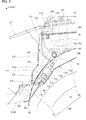
Fig. 3 , in order to make it easy to understand the shapes of thestorage box 27 and therear fender 73, thestorage box 27 and therear fender 73 are shown with bold outlines.
As shown inFig. 3 , thefuel supply device 54 includes: thefuel tank 28; afuel pump 91 mounted on a top of thefuel tank 28; aprimary fuel filter 93 attached to thefuel pump 91; asecondary fuel filter 96 connected to thefuel pump 91 attached with theprimary fuel filter 93 via afuel pipe 94; thepressure regulator 98 connected to thesecondary fuel filter 96 via afuel pipe 97; theinjector 102 connected to thepressure regulator 98 via a fuel pipe (a secondary supply pipe) 101; and the return pipe 118 (refer toFig. 6 ) connecting thepressure regulator 98 and thefuel tank 28, and theinjector 102 is attached to the throttle body 52 (refer toFig. 1 ) of the air-intake device 47 (refer toFig. 1 ). - In the
fuel supply device 54,fuel supply piping 103 is formed that feeds fuel from thefuel tank 28 to thethrottle body 52 on the side of the engine 25 (refer toFig. 1 ).
Thefuel supply piping 103 is composed offuel pipes fuel pipes fuel pump 91 to thepressure regulator 98. - As shown in
Fig. 4 , thestorage box 27 is formed so large that a full-face type helmet 68 can be stored therein. Note thatreference sign 27a is a seat-mounting portion provided at a front end portion of thestorage box 27 in order to raisably mount theseat 67 on thestorage box 27. - The
seat 67 is of the tandem type composed of arider seat 67a on which a rider seats, and apillion passenger seat 67b that is formed behind therider seat 67a at a position one step higher than the rider seat for a pillion passenger to seat. - A stepped
portion 67c is formed between therider seat 67a and thepillion passenger seat 67b, and an upper end of thefuel pump 91 is disposed below the steppedportion 67c.
Thefuel pump 91 is provided with, at the top thereof, afuel discharge portion 104 projecting upward, and thefuel pipe 94 is connected to thefuel discharge portion 104. - The
secondary fuel filter 96 is removably attached to an upper surface of therear fender 73, and is disposed between thestorage box 27 and therear fender 73 and between the left and right rear frames 14, 16 (only thenear reference sign 14 is shown). - The
pressure regulator 98 is removably held by aregulator bracket 105 attached to a front portion of thecross member 81, and is disposed in front of thestorage box 27 and above themain frame 13, above front portions of the rear frames 14, 16, and above thecross member 81 in a side view. - As shown in
Fig. 5 , on arear wall 27c of thestorage box 27, there are provided: a pair of left and right upper mountingportions near reference sign 27d is shown) that projects rearward so as to be attached to the rear-end extending portion 19; an uppervertical wall portion 27f extending downward from these upper mountingportions oblique wall portion 27g extending forward diagonally downward from a lower end of the uppervertical wall portion 27f; a lowervertical wall portion 27j extending downward from the upperoblique wall portion 27g; and alower support portion 27k extending forward from the lowervertical wall portion 27j so as to be supported by thefirst cross pipe 83 via arubber 107. - The upper
vertical wall portion 27f, the upperoblique wall portion 27g, and the lowervertical wall portion 27j of the above-mentionedrear wall 27c are, as a whole, inclined so that the uppervertical wall portion 27f is positioned behind the lowervertical wall portion 27j. - As shown in
Fig. 3 , therear fender 73 projects upward in a projecting manner so as to form an arc in order to cover front, upper, and rear portions of the rear wheel 33 (refer toFig. 1 ), is composed of afront portion 73a and arear portion 73b which are formed at the front and rear with a peak of the arc as a boundary, and has a projectingportion 73c formed in the projecting manner radially outward so as to prevent the interference with therear wheel 33 over thefront portion 73a and therear portion 73b. - With reference back to
Fig. 5 , thefront portion 73a of therear fender 73 is disposed so as to face therear wall 27c of thestorage box 27, and is formed so as to gradually separate rearward from therear wall 27c up to its upper end. Consequently, aspace 108 formed between therear wall 27c of thestorage box 27 and thefront portion 73a of therear fender 73 gradually increases in the longitudinal direction up to an upper end of thespace 108. - In the
front portion 73a of therear fender 73, a recessedportion 73d recessed toward therear wheel 33 side is formed at a position facing therear wall 27c of thestorage box 27, specifically the upperinclined wall 27g, and a part of thesecondary fuel filter 96 is accommodated in the recessedportion 73d. - The
secondary fuel filter 96 is removably held at a bottom 73e of the recessedportion 73d via an integrally or separately providedholder 111, and is disposed so as to incline forward and downward along the rearinclined portions portion 73c of therear fender 73. Note that reference signs 115, 116 are connecting assemblies provided at respective end portions of thefuel pipes secondary fuel filter 96. - The
holder 111 is composed of a pair of holdingmembers 112, 112 (only thenear reference sign 112 is shown) projecting from abottom portion 73a thereof; and arubber fastening member 113 having holes formed to press-fit to the holdingmembers fastening member 113 is fit into an outer peripheral portion of thesecondary fuel filter 96. - As shown in
Fig. 6 , therear fender 73 is locked to afirst cross pipe 83 and asecond cross pipe 84 of thevehicle body frame 11. Note thatreference sign 73g designates a front locking portion provided at the center in the vehicle width direction of a front portion of therear fender 73. - The
secondary fuel filter 96 is disposed along the rearinclined portions portion 73c of therear fender 73 in a longitudinal direction.
Thefuel supply device 54 has thereturn pipe 118, one end of which is connected to thepressure regulator 98 and the other end of which is connected to areturn port 28b provided at thebottom portion 28a of thefuel tank 28. - The
secondary fuel filter 96 is disposed to the left of the projectingportion 73c of therear fender 73 and between therear frames portion 73c and the onerear frame 14. - Out of the
space 108 shown inFig. 5 , formed between therear wall 27c of thestorage box 27 and thefront portion 73a of therear fender 73, especially aspace 121 shown inFig. 6 , between the projectingportion 73c and therear frame 14 is a space which has not been used, and therefore it is possible to effectively utilize thespace 121 by disposing thesecondary fuel filter 96 in such aspace 121, and thereby to make a vehicle body size smaller than where a space is specially provided in the vehicle body to dispose thesecondary fuel filter 96. - Furthermore, since the
secondary fuel filter 96 is disposed between and along the projectingportion 73c and therear frame 14, it is possible to easily dispose it even if thespace 121 is small, and thereby to utilize thespace 121 more effectively. - As shown in
Fig. 7 , theupper mounting portions storage box 27 and theflange portion 28d of thefuel tank 28 are jointly fastened to both front ends of the rear-end extending portion 19 of the rear frames 14, 16 via amount rubber 123 provided between theupper mounting portions flange portion 28d. - Specifically, in
Fig. 5 , at the leftupper mounting portion 27d side of thestorage box 27, theflange portion 28d, themount rubber 123, and the upper mountingportion 27d of thestorage box 27 are mounted in this order on the rear-end extending portion 19 of the rear frames 14, 16, and abolt 124 penetrates through the upper mountingportion 27d, themount rubber 123, theflange portion 28d, and the rear-end extending portion 19 and is screwed into anut 125 provided in the rear-end extending portion 19. - Likewise, at the right
upper mounting portion 27e (refer toFig. 7 ) of thestorage box 27, theflange portion 28d, themount rubber 123, and the upper mountingportion 27e of thestorage box 27 are mounted in this order on the rear-end extending portion 19 of the rear frames 14, 16, and thebolt 124 penetrates through the upper mountingportion 27e, therubber 123, theflange portion 28d and the rear-end extending portion 19, and is screwed into thenut 125 provided in the rear-end extending portion 19. - Also, as shown in
Fig. 7 , thefuel pump 91 is provided with aflange 127 at its upper portion and theflange 127 is attached to a top surface of thefuel tank 28.
Theflange 127 is provided with thefuel discharge portion 104 that passes through theflange 127, projects upward, and extends to the left side of the vehicle body. - The
fuel pipe 97 constituting thefuel supply device 54 is disposed above therear frame 14, extending from thesecondary fuel filter 96 to thepressure regulator 98 along therear frame 14, and thereturn pipe 118 is disposed above therear frame 16, extending from thepressure regulator 98 to a lower portion of thefuel tank 28 along the otherrear frame 16. - As shown in
Fig. 8 , thesecondary fuel filter 96 is composed of afilter case 131 and afilter assembly 132 housed inside thefilter case 131, and pores of thefilter assembly 132 are made finer than those of the primary fuel filter 93 (refer toFig. 4 ) .
Thefilter case 131 is composed of a bottomedtubular case body 134 and acase cover 136 to close an opening portion of thecase body 134. - The
case body 134 is provided with afuel suction port 134a that is connected to the fuel pipe 94 (refer toFig. 5 ) on the fuel tank 28 (refer toFig. 5 ) side for sucking fuel, and thecase cover 136 is provide with afuel discharge port 136a that is connected to the fuel pipe 97 (refer toFig. 5 ) on the injector 102 (refer toFig. 3 ) side for discharging fuel. - The
filter assembly 132 is composed of atubular filter 141 made of a filter paper and frames 142, 143 supporting both ends of thefilter 141, and is fixed by sandwiching it between thecase body 134 and thecase cover 136. - Fuel is sucked into the
filter case 131 from thefuel suction port 134a, filtered while flowing to pass from an outerperipheral surface 141a of thefilter 141 to an innerperipheral surface 141b thereof, and then discharged outside thefilter case 131 through thefuel discharge port 136a. - As shown in
Fig. 9 , thepressure regulator 98 is composed of acase 161 with a resinfirst case 161E and a resinsecond case 161F joined together; a sphericalsteel valve element 162 which opens and closes a through-hole 161a opened in a bottom of one end of thecase 161; acompression coil spring 163 that presses thevalve element 162 to close the through-hole 161a; afuel suction port 165 in which the through-hole 161a is opened; afuel discharge port 166 formed at a midpoint of thefuel suction port 165; and afuel return port 167 having a through-hole 161c that is opened in a bottom of the other end of thecase 161. - The
fuel suction port 165 is connected to the secondary fuel filter 96 (refer toFig. 6 ), thefuel discharge port 166 is connected to the injector 102 (refer toFig. 3 ), and thefuel return port 167 is connected to the fuel tank 28 (refer toFig 6 ). - As shown in
Figs. 1 ,3 , and7 , in the fuel supply device 54 including the storage box 27 disposed below the seat 67 of the motorcycle 10, and the fuel tank 28 disposed behind the storage box 27, the air-intake device 47 and the injector 102 as a fuel injection device for the engine 25 being disposed in front of the storage box 27, fuel in the fuel tank 28 being press-fed into the injector 102 by the fuel pump 91 disposed inside the fuel tank 28, the pressure regulator 98 being disposed at a midpoint of the fuel supply piping 103 interconnecting the fuel pump 91 and the injector 102, fuel being supplied from the fuel pump 91 to the pressure regulator 98 via the fuel pipe 106 as a first supply pipe, fuel being supplied from the pressure regulator 98 to the injector 102 via the fuel pipe 101 as a second supply pipe, and extra fuel being returned from the pressure regulator 98 to the fuel tank 28 via the return pipe 118, wherein the fuel pipe 106 and the return pipe 118 are arranged in a U shape by placing the pressure regulator 98 in front of the storage box 27, placing the fuel pipe 106 and the return pipe 118 on one side and another side of the storage box 27 respectively, and placing the pressure regulator 98 in front of the storage box 27.
According to the abovementioned configuration, it is possible to make curvatures of thefuel pipe 106 and thereturn pipe 118 gentle and thereby to prevent stress concentration. - Also, in the
pressure regulator 98, since thefuel pipe 106 and thereturn pipe 118 are connected to one side and the other side in the vehicle width direction respectively, it is possible to shorten thefuel pipe 106 and thereturn pipe 118 by reducing bent portions, and also to easily dispose thefuel pipe 106 and thereturn pipe 118 and reduce a cost thereof. - As shown in
Figs. 1 and7 , since theengine 25 is provided with thecylinder portion 42 projecting forward horizontally, thepressure regulator 98 is disposed above thecrankcase 41 of theengine 25 and behind theinjector 102, and thefuel pipe 101 as secondary supply piping is disposed along thevehicle body frame 11, specifically themain frame 13, extending in a longitudinal direction, it is possible to protect thepressure regulator 98 with thecrankcase 41 of theengine 25 and also to protect thefuel pipe 101 with themain frame 13. - Furthermore, since the
engine 25 is provided with thehorizontal cylinder portion 42, a distance between thepressure regulator 98 and theinjector 102 can be made longer in a longitudinal direction than, for example, an engine whose cylinder portion extends upward from a crankcase. - Consequently, it is possible to secure a large capacity in the
fuel pipe 101 and thereby suppress fuel pulsation, and also to simplify the layout by extending thefuel pipe 101 more straight. - As shown in
Figs. 2 and7 , since thevehicle body frame 11 is provided with a singlemain frame 13 extending obliquely downward and rearward from thehead pipe 12 and the rear frames 14, 16 as a seat frame bifurcating left and right from themain frame 13 in front of thestorage box 27, thepressure regulator 98 is disposed between the left and right rear frames 14, 16 in a plain view, and thefuel pipe 101 is connected, at the rear end thereof, to thefuel discharge port 166 as a front side joint portion provided on thepressure regulator 98, extends while curving over themain frame 13 from one of the left and right edges of themain frame 13 to downward of themain frame 13 above thecylinder portion 42 and within the width of it, and is connected, at a front end thereof, to theinjector 102, it is possible to protect thefuel pipe 101 with themain frame 13 and thecylinder portion 42. - As shown in
Figs. 1 and5 , since therear wheel 33 of themotorcycle 10 is attached to the rear end of theswing arm 32 vertically-swingably supported by thevehicle body frame 11, and thesecondary fuel filter 96 as a fuel filter disposed at a midpoint of thefuel pipe 106 is disposed within a swinging range of therear wheel 33 in a side view, it is possible to easily prevent an interference between thesecondary fuel filter 96 and therear wheel 33 by disposing thesecondary fuel filter 96 on one side in the vehicle width direction and outside of the external side of the rear wheel at the time of a maximum movement of the rear wheel (the position of therear wheel 33 at this time is shown inFig. 7 ). - As shown in
Figs. 1 and7 , since thefuel pipe 106, thereturn pipe 118, thesecondary fuel filter 96, and thepressure regulator 98 are disposed inside thevehicle body frame 11 in a plain view, and theleg shield 64 to cover legs of the occupant sitting on theseat 67 from the front covers thefuel pipe 101 at the rear of the center thereof, it is possible to protect thefuel pipe 106, thereturn pipe 118, thesecondary fuel filter 96, and thepressure regulator 98 with thevehicle body frame 11 and improve the appearance by covering thepressure regulator 98 with theleg shield 64, and thus there is no need for providing a special cover member to cover thepressure regulator 98, allowing a reduction in the number of components. - Also, since the fuel contains ethanol and ethanol concentration in the fuel is determined from components of the exhaust gas from the
engine 25 by means of theECU 60 as a control device, the fuel injection control by theinjector 102 is switched according to the ethanol concentration, and thefuel pipe 101 is made of a rubber hose, it is possible to suppress the pulsation of fuel fed into theinjector 102 and thereby stabilize the combustion of theengine 25 by employing the flexible rubber hose for thefuel pipe 101. - Furthermore, since the fuel injection control by the
injector 102 is switched by theECU 60 according to ethanol concentration, it is possible to appropriately control the combustion of theengine 25 and thereby improve engine performance. - As shown in
Fig. 7 , since thefuel pipe 106 and thereturn pipe 118 are made of the resin hose, the outer diameters of thefuel pipe 106 and thereturn pipe 118 can be reduced, and it is possible to make a piping work easier especially for a small vehicle with a small body space and also reduce the cost as compared to a rubber hose. - As shown in
Figs. 5 and7 , since thefuel pump 91 is provided with thefuel discharge port 104 as a fuel discharge joint passing through theflange 127 closing an opening in the top of thefuel tank 28 and bending to one side in the vehicle with direction, and thefuel pipe 106 is connected to thefuel discharge port 104 from one side in the vehicle width direction, it is possible to make it easier to dispose thefuel pipe 106 on one side in the vehicle width direction. - As shown in
Fig. 4 , theseat 67 is of the tandem type having therider seat 67a at the front and thepillion passenger seat 67b at the rear to allow two persons to seat, the steppedportion 67c is formed between therider seat 67a and thepillion passenger seat 67b, and thefuel discharge port 104 is provided below the steppedportion 67c, it is possible to secure a seat thickness even if thefuel discharge port 104 projecting upward is provided, thus allowing a comfortable ride to be maintained. - A fuel supply device of the present invention is preferable for a motorcycle.
-
- 10...Motorcycle
- 11...Vehicle body frame
- 12...Head pipe
- 13...Main frame
- 14, 16...Seat frame (Rear frame)
- 25...Engine
- 27...Storage box
- 28...Fuel tank
- 32...Swing arm
- 33...Rear wheel
- 41...Crankcase
- 42...Cylinder portion
- 47...Air-intake device
- 54...Fuel supply device
- 60...Control device (Engine control unit)
- 64...Leg shield
- 67...Seat
- 67a...Seat portion (Rider sear)
- 67b...Seat portion (Pillion passenger seat) 67c...Stepped portion
- 91...Fuel pump
- 96...Fuel filter (Secondary fuel filter)
- 98...Pressure regulator
- 101...Secondary supply pipe (Fuel pipe)
- 102...Fuel injection device (Injector)
- 104...Fuel discharge joint (Fuel discharge portion)
- 106...First supply pipe (Fuel pipe)
- 118...Return pipe
- 127...Flange
- 166...Joint portion (Fuel discharge port)
Claims (10)
- A fuel supply device comprising:a storage box disposed below a seat of a motorcycle; anda fuel tank provided behind the storage box, an air-intake device and a fuel injection device for an engine being disposed in front of the storage box, fuel in the fuel tank being press-fed to the fuel injection device by a fuel pump disposed inside the fuel tank, a pressure regulator being disposed at a midpoint of fuel supply piping interconnecting the fuel pump and the fuel injecting device, fuel being supplied from the fuel pump to the pressure regulator via a first supply pipe constituting the fuel supply piping, fuel being supplied from the pressure regulator to the fuel injection device via a second supply pipe constituting the fuel supply piping, and excess fuel being returned from the pressure regulator to the fuel tank via a return pipe,wherein: the pressure regulator is disposed in front of the storage box;the first supply pipe and the return pipe are disposed on one side and another side of the storage box via the pressure regulator; andthe first supply pipe and the return pipe are disposed so as to form a U shape.
- The fuel supply device according to claim 1, wherein the first supply pipe and the return pipe are connected respectively to one side and another side, across the vehicle body, of the pressure regulator.
- The fuel supply device according to claim 1 or claim 2,
wherein: the engine is provided with a cylinder portion horizontally projecting forward;
the pressure regulator is disposed above a crankcase of the engine and behind the fuel injection device; and
the second supply pipe is disposed along a vehicle body frame extending in a longitudinal direction. - The fuel supply device according to one of claims 1 through 3,
wherein: the vehicle body frame is provided with one main frame extending obliquely downward and rearward from a head pipe and a seat frame bifurcated left and right from the main frame in front of the storage box;
the pressure regulator is disposed between left and right seat frames in a plain view; and
a rear end of the second supply pipe is connected to a front side joint portion provided on the pressure regulator and extends in a curve from one of left and right edges of the main frame over the main frame to downward of the main frame above a cylinder portion and within the left and right width of the cylinder portion so that the front end of the second supply pipe is connected to the fuel injection device. - The fuel supply device according to one of claims 1 through 4,
wherein: a rear wheel of the motorcycle is attached to a rear end of a swing arm supported by the vehicle body frame swingably up and down; and
a fuel filter disposed at a midpoint of the first supply pipe is disposed within a swingable range of the rear wheel in a side view. - The fuel supply device according to one of claims 1 through 5,
wherein: the first supply pipe, the return pipe, the fuel filter, and the pressure regulator are disposed inside the vehicle body frame in the plain view; and
a leg shield covering the legs of an occupant sitting on the seat from the front covers the second supply pipe at a rear of the center portion thereof. - The fuel supply device according to one of claims 1 through 6,
wherein: fuel contains ethanol, ethanol concentration in fuel is determined from components of an exhaust gas from the engine, and control of fuel injection by the fuel injection device is switched according to the ethanol concentration; and
the second supply pipe is made of a rubber hose. - The fuel supply device according to one of claims 1 through 7, wherein the first supply pipe and the return pipe are made of a resin hose.
- The fuel supply device according to one of claims 1 through 8,
wherein: the fuel pump is provided with a fuel discharge joint passing through a flange that closes an opening in a top surface of the fuel tank and bends toward one side in a vehicle width direction; and
the first supply pipe is connected to the fuel discharge joint from one side in the vehicle width direction. - The fuel supply device according to claim 9,
wherein: the seat is of a tandem type having front and back seating portions for allowing two persons to sit thereon; and
a stepped portion is formed between the front and back seating portions and the fuel discharge joint is provided below the stepped portion.
Applications Claiming Priority (1)
| Application Number | Priority Date | Filing Date | Title |
|---|---|---|---|
| JP2010019206A JP5520623B2 (en) | 2010-01-29 | 2010-01-29 | Fuel supply device |
Publications (3)
| Publication Number | Publication Date |
|---|---|
| EP2353982A2 true EP2353982A2 (en) | 2011-08-10 |
| EP2353982A3 EP2353982A3 (en) | 2012-09-05 |
| EP2353982B1 EP2353982B1 (en) | 2014-09-17 |
Family
ID=43735608
Family Applications (1)
| Application Number | Title | Priority Date | Filing Date |
|---|---|---|---|
| EP11151996.3A Not-in-force EP2353982B1 (en) | 2010-01-29 | 2011-01-25 | Motorcycle |
Country Status (4)
| Country | Link |
|---|---|
| US (1) | US8387736B2 (en) |
| EP (1) | EP2353982B1 (en) |
| JP (1) | JP5520623B2 (en) |
| BR (1) | BRPI1100065B1 (en) |
Cited By (1)
| Publication number | Priority date | Publication date | Assignee | Title |
|---|---|---|---|---|
| EP2639146A1 (en) * | 2012-03-15 | 2013-09-18 | Yamaha Hatsudoki Kabushiki Kaisha | Straddle-type vehicle |
Families Citing this family (10)
| Publication number | Priority date | Publication date | Assignee | Title |
|---|---|---|---|---|
| US8387089B1 (en) | 2005-05-06 | 2013-02-26 | Rovi Guides, Inc. | Systems and methods for providing a scan |
| JP5184479B2 (en) * | 2009-09-29 | 2013-04-17 | 本田技研工業株式会社 | Motorcycle fuel supply system |
| BR112013002309B1 (en) * | 2010-07-30 | 2019-09-03 | Honda Motor Co Ltd | vehicle fuel tank mount |
| JP5715839B2 (en) * | 2011-01-31 | 2015-05-13 | 本田技研工業株式会社 | Saddle riding |
| JP5894823B2 (en) | 2012-03-19 | 2016-03-30 | 本田技研工業株式会社 | Fuel supply structure for vehicles |
| JP5961492B2 (en) * | 2012-08-31 | 2016-08-02 | 本田技研工業株式会社 | Rear structure of saddle riding type vehicle |
| JP5865323B2 (en) * | 2013-09-30 | 2016-02-17 | 本田技研工業株式会社 | Saddle riding |
| JP5775560B2 (en) * | 2013-12-06 | 2015-09-09 | 本田技研工業株式会社 | Saddle riding |
| US9561831B2 (en) * | 2015-07-10 | 2017-02-07 | Paul Yaffe | Motorcycle fairing support member and assembly and method of supporting a motorcycle fairing |
| CN111886153A (en) * | 2018-02-20 | 2020-11-03 | 印度商宜诺摩托克普有限公司 | Fuel storage system |
Family Cites Families (21)
| Publication number | Priority date | Publication date | Assignee | Title |
|---|---|---|---|---|
| JPH0245649A (en) * | 1988-08-05 | 1990-02-15 | Honda Motor Co Ltd | Fuel feed conduit for engine |
| US5769041A (en) * | 1996-04-26 | 1998-06-23 | Yamaha Hatsudoki Kabushiki Kaisha | Two cycle fuel injection engine |
| JP3816210B2 (en) * | 1997-09-30 | 2006-08-30 | 本田技研工業株式会社 | Body structure of a low-floor motorcycle |
| JP4555413B2 (en) * | 1999-03-02 | 2010-09-29 | 本田技研工業株式会社 | Fuel injection device for backbone type motorcycle |
| JP4077266B2 (en) * | 2002-07-30 | 2008-04-16 | ヤマハ発動機株式会社 | Fuel supply device for motorcycle engine |
| JP4176456B2 (en) * | 2002-11-29 | 2008-11-05 | 本田技研工業株式会社 | Fuel system layout structure for motorcycles |
| JP4021339B2 (en) * | 2003-02-12 | 2007-12-12 | 本田技研工業株式会社 | Fuel supply system for motorcycles |
| JP4453303B2 (en) * | 2003-08-28 | 2010-04-21 | スズキ株式会社 | Scooter type motorcycle |
| ES2380179T3 (en) * | 2004-03-30 | 2012-05-09 | Yamaha Hatsudoki Kabushiki Kaisha | Motor vehicle of the type of riding or astride |
| JP2006088892A (en) * | 2004-09-24 | 2006-04-06 | Yamaha Motor Co Ltd | Saddle riding type vehicle |
| JP2007107505A (en) * | 2005-10-17 | 2007-04-26 | Yamaha Motor Co Ltd | Motorcycle |
| JP2007118628A (en) * | 2005-10-24 | 2007-05-17 | Yamaha Motor Co Ltd | Saddle riding type vehicle |
| JP2007118627A (en) * | 2005-10-24 | 2007-05-17 | Yamaha Motor Co Ltd | Fuel tank assembly and saddle riding type vehicle equipped therewith |
| JP4888114B2 (en) * | 2006-12-28 | 2012-02-29 | スズキ株式会社 | Motorcycle fuel supply system |
| KR101020362B1 (en) * | 2008-02-28 | 2011-03-09 | 혼다 기켄 고교 가부시키가이샤 | Vehicular fuel supply equipment |
| JP4889669B2 (en) * | 2008-03-06 | 2012-03-07 | 本田技研工業株式会社 | Fuel supply device |
| JP4564083B2 (en) * | 2008-07-07 | 2010-10-20 | 本田技研工業株式会社 | Fuel system layout structure for motorcycles |
| JP5030914B2 (en) * | 2008-09-29 | 2012-09-19 | 本田技研工業株式会社 | Canister mounting structure for motorcycles |
| JP5175166B2 (en) * | 2008-12-08 | 2013-04-03 | 川崎重工業株式会社 | Alternative fuel concentration estimation device and alternative fuel concentration estimation method |
| JP5364524B2 (en) * | 2009-09-30 | 2013-12-11 | 本田技研工業株式会社 | Motorcycle |
| JP5371669B2 (en) * | 2009-09-30 | 2013-12-18 | 本田技研工業株式会社 | Scooter type vehicle |
-
2010
- 2010-01-29 JP JP2010019206A patent/JP5520623B2/en not_active Expired - Fee Related
-
2011
- 2011-01-21 US US13/011,121 patent/US8387736B2/en not_active Expired - Fee Related
- 2011-01-25 EP EP11151996.3A patent/EP2353982B1/en not_active Not-in-force
- 2011-01-27 BR BRPI1100065-1A patent/BRPI1100065B1/en not_active IP Right Cessation
Non-Patent Citations (1)
| Title |
|---|
| None |
Cited By (1)
| Publication number | Priority date | Publication date | Assignee | Title |
|---|---|---|---|---|
| EP2639146A1 (en) * | 2012-03-15 | 2013-09-18 | Yamaha Hatsudoki Kabushiki Kaisha | Straddle-type vehicle |
Also Published As
| Publication number | Publication date |
|---|---|
| EP2353982A3 (en) | 2012-09-05 |
| JP2011157849A (en) | 2011-08-18 |
| EP2353982B1 (en) | 2014-09-17 |
| US8387736B2 (en) | 2013-03-05 |
| BRPI1100065A2 (en) | 2013-04-30 |
| JP5520623B2 (en) | 2014-06-11 |
| US20110186370A1 (en) | 2011-08-04 |
| BRPI1100065B1 (en) | 2020-11-17 |
Similar Documents
| Publication | Publication Date | Title |
|---|---|---|
| EP2353982B1 (en) | Motorcycle | |
| JP5371669B2 (en) | Scooter type vehicle | |
| EP2305546B1 (en) | Motorcycle with a fuel filter behind a luggage box | |
| JP5227932B2 (en) | Scooter type vehicle | |
| KR100359702B1 (en) | Fuel Injection Device for Backbone Type Autobicycle | |
| US20160069306A1 (en) | Air cleaner for motorcycle | |
| KR101254909B1 (en) | Saddle type vehicle | |
| EP2881313B1 (en) | Body frame structure for saddle-ride type vehicle | |
| US6910716B2 (en) | Fuel tank mounting structure for motorcycles | |
| JP2010052625A (en) | Motorcycle | |
| JP5719256B2 (en) | Motorcycle | |
| JP2007008357A (en) | Air intake structure of motorcycle | |
| US8196989B2 (en) | Seat cowl structure of saddle-riding type vehicle | |
| JP2007055564A (en) | Fuel piping arrangement structure | |
| JP2007099143A (en) | Fuel feeding device, and motorcycle provided with the fuel feeding device | |
| JP5820121B2 (en) | Intake device for saddle-ride type vehicles | |
| JP6309406B2 (en) | Saddle riding vehicle | |
| JP5180686B2 (en) | Fuel injection device for backbone type motorcycle | |
| JP2008261340A5 (en) | ||
| JP4673870B2 (en) | Fuel injection device for backbone type motorcycle | |
| EP2371689B1 (en) | Motorcycle | |
| JP2007297049A5 (en) | ||
| JP2010159771A (en) | Fuel injection device in backbone type motorcycle |
Legal Events
| Date | Code | Title | Description |
|---|---|---|---|
| PUAI | Public reference made under article 153(3) epc to a published international application that has entered the european phase |
Free format text: ORIGINAL CODE: 0009012 |
|
| 17P | Request for examination filed |
Effective date: 20110125 |
|
| AK | Designated contracting states |
Kind code of ref document: A2 Designated state(s): AL AT BE BG CH CY CZ DE DK EE ES FI FR GB GR HR HU IE IS IT LI LT LU LV MC MK MT NL NO PL PT RO RS SE SI SK SM TR |
|
| AX | Request for extension of the european patent |
Extension state: BA ME |
|
| PUAL | Search report despatched |
Free format text: ORIGINAL CODE: 0009013 |
|
| AK | Designated contracting states |
Kind code of ref document: A3 Designated state(s): AL AT BE BG CH CY CZ DE DK EE ES FI FR GB GR HR HU IE IS IT LI LT LU LV MC MK MT NL NO PL PT RO RS SE SI SK SM TR |
|
| AX | Request for extension of the european patent |
Extension state: BA ME |
|
| RIC1 | Information provided on ipc code assigned before grant |
Ipc: F02D 19/08 20060101ALI20120731BHEP Ipc: B62J 37/00 20060101AFI20120731BHEP Ipc: F02M 37/00 20060101ALI20120731BHEP |
|
| RIC1 | Information provided on ipc code assigned before grant |
Ipc: F02D 19/08 20060101ALI20140307BHEP Ipc: F02M 37/00 20060101ALI20140307BHEP Ipc: B62J 37/00 20060101AFI20140307BHEP Ipc: F02D 19/06 20060101ALI20140307BHEP Ipc: F02M 37/22 20060101ALI20140307BHEP Ipc: F02M 69/04 20060101ALI20140307BHEP |
|
| GRAP | Despatch of communication of intention to grant a patent |
Free format text: ORIGINAL CODE: EPIDOSNIGR1 |
|
| INTG | Intention to grant announced |
Effective date: 20140424 |
|
| GRAS | Grant fee paid |
Free format text: ORIGINAL CODE: EPIDOSNIGR3 |
|
| GRAA | (expected) grant |
Free format text: ORIGINAL CODE: 0009210 |
|
| AK | Designated contracting states |
Kind code of ref document: B1 Designated state(s): AL AT BE BG CH CY CZ DE DK EE ES FI FR GB GR HR HU IE IS IT LI LT LU LV MC MK MT NL NO PL PT RO RS SE SI SK SM TR |
|
| REG | Reference to a national code |
Ref country code: GB Ref legal event code: FG4D |
|
| REG | Reference to a national code |
Ref country code: CH Ref legal event code: EP |
|
| REG | Reference to a national code |
Ref country code: IE Ref legal event code: FG4D |
|
| REG | Reference to a national code |
Ref country code: AT Ref legal event code: REF Ref document number: 687552 Country of ref document: AT Kind code of ref document: T Effective date: 20141015 |
|
| REG | Reference to a national code |
Ref country code: DE Ref legal event code: R096 Ref document number: 602011009894 Country of ref document: DE Effective date: 20141030 |
|
| PG25 | Lapsed in a contracting state [announced via postgrant information from national office to epo] |
Ref country code: SE Free format text: LAPSE BECAUSE OF FAILURE TO SUBMIT A TRANSLATION OF THE DESCRIPTION OR TO PAY THE FEE WITHIN THE PRESCRIBED TIME-LIMIT Effective date: 20140917 Ref country code: GR Free format text: LAPSE BECAUSE OF FAILURE TO SUBMIT A TRANSLATION OF THE DESCRIPTION OR TO PAY THE FEE WITHIN THE PRESCRIBED TIME-LIMIT Effective date: 20141218 Ref country code: LT Free format text: LAPSE BECAUSE OF FAILURE TO SUBMIT A TRANSLATION OF THE DESCRIPTION OR TO PAY THE FEE WITHIN THE PRESCRIBED TIME-LIMIT Effective date: 20140917 Ref country code: NO Free format text: LAPSE BECAUSE OF FAILURE TO SUBMIT A TRANSLATION OF THE DESCRIPTION OR TO PAY THE FEE WITHIN THE PRESCRIBED TIME-LIMIT Effective date: 20141217 Ref country code: FI Free format text: LAPSE BECAUSE OF FAILURE TO SUBMIT A TRANSLATION OF THE DESCRIPTION OR TO PAY THE FEE WITHIN THE PRESCRIBED TIME-LIMIT Effective date: 20140917 |
|
| REG | Reference to a national code |
Ref country code: NL Ref legal event code: VDEP Effective date: 20140917 |
|
| REG | Reference to a national code |
Ref country code: LT Ref legal event code: MG4D |
|
| PG25 | Lapsed in a contracting state [announced via postgrant information from national office to epo] |
Ref country code: HR Free format text: LAPSE BECAUSE OF FAILURE TO SUBMIT A TRANSLATION OF THE DESCRIPTION OR TO PAY THE FEE WITHIN THE PRESCRIBED TIME-LIMIT Effective date: 20140917 Ref country code: LV Free format text: LAPSE BECAUSE OF FAILURE TO SUBMIT A TRANSLATION OF THE DESCRIPTION OR TO PAY THE FEE WITHIN THE PRESCRIBED TIME-LIMIT Effective date: 20140917 Ref country code: RS Free format text: LAPSE BECAUSE OF FAILURE TO SUBMIT A TRANSLATION OF THE DESCRIPTION OR TO PAY THE FEE WITHIN THE PRESCRIBED TIME-LIMIT Effective date: 20140917 Ref country code: CY Free format text: LAPSE BECAUSE OF FAILURE TO SUBMIT A TRANSLATION OF THE DESCRIPTION OR TO PAY THE FEE WITHIN THE PRESCRIBED TIME-LIMIT Effective date: 20140917 |
|
| REG | Reference to a national code |
Ref country code: AT Ref legal event code: MK05 Ref document number: 687552 Country of ref document: AT Kind code of ref document: T Effective date: 20140917 |
|
| PG25 | Lapsed in a contracting state [announced via postgrant information from national office to epo] |
Ref country code: NL Free format text: LAPSE BECAUSE OF FAILURE TO SUBMIT A TRANSLATION OF THE DESCRIPTION OR TO PAY THE FEE WITHIN THE PRESCRIBED TIME-LIMIT Effective date: 20140917 |
|
| PG25 | Lapsed in a contracting state [announced via postgrant information from national office to epo] |
Ref country code: IS Free format text: LAPSE BECAUSE OF FAILURE TO SUBMIT A TRANSLATION OF THE DESCRIPTION OR TO PAY THE FEE WITHIN THE PRESCRIBED TIME-LIMIT Effective date: 20150117 Ref country code: SK Free format text: LAPSE BECAUSE OF FAILURE TO SUBMIT A TRANSLATION OF THE DESCRIPTION OR TO PAY THE FEE WITHIN THE PRESCRIBED TIME-LIMIT Effective date: 20140917 Ref country code: EE Free format text: LAPSE BECAUSE OF FAILURE TO SUBMIT A TRANSLATION OF THE DESCRIPTION OR TO PAY THE FEE WITHIN THE PRESCRIBED TIME-LIMIT Effective date: 20140917 Ref country code: RO Free format text: LAPSE BECAUSE OF FAILURE TO SUBMIT A TRANSLATION OF THE DESCRIPTION OR TO PAY THE FEE WITHIN THE PRESCRIBED TIME-LIMIT Effective date: 20140917 Ref country code: ES Free format text: LAPSE BECAUSE OF FAILURE TO SUBMIT A TRANSLATION OF THE DESCRIPTION OR TO PAY THE FEE WITHIN THE PRESCRIBED TIME-LIMIT Effective date: 20140917 Ref country code: PT Free format text: LAPSE BECAUSE OF FAILURE TO SUBMIT A TRANSLATION OF THE DESCRIPTION OR TO PAY THE FEE WITHIN THE PRESCRIBED TIME-LIMIT Effective date: 20150119 Ref country code: CZ Free format text: LAPSE BECAUSE OF FAILURE TO SUBMIT A TRANSLATION OF THE DESCRIPTION OR TO PAY THE FEE WITHIN THE PRESCRIBED TIME-LIMIT Effective date: 20140917 |
|
| PG25 | Lapsed in a contracting state [announced via postgrant information from national office to epo] |
Ref country code: AT Free format text: LAPSE BECAUSE OF FAILURE TO SUBMIT A TRANSLATION OF THE DESCRIPTION OR TO PAY THE FEE WITHIN THE PRESCRIBED TIME-LIMIT Effective date: 20140917 Ref country code: PL Free format text: LAPSE BECAUSE OF FAILURE TO SUBMIT A TRANSLATION OF THE DESCRIPTION OR TO PAY THE FEE WITHIN THE PRESCRIBED TIME-LIMIT Effective date: 20140917 |
|
| REG | Reference to a national code |
Ref country code: DE Ref legal event code: R097 Ref document number: 602011009894 Country of ref document: DE |
|
| PG25 | Lapsed in a contracting state [announced via postgrant information from national office to epo] |
Ref country code: BE Free format text: LAPSE BECAUSE OF NON-PAYMENT OF DUE FEES Effective date: 20150131 |
|
| PLBE | No opposition filed within time limit |
Free format text: ORIGINAL CODE: 0009261 |
|
| STAA | Information on the status of an ep patent application or granted ep patent |
Free format text: STATUS: NO OPPOSITION FILED WITHIN TIME LIMIT |
|
| PG25 | Lapsed in a contracting state [announced via postgrant information from national office to epo] |
Ref country code: DK Free format text: LAPSE BECAUSE OF FAILURE TO SUBMIT A TRANSLATION OF THE DESCRIPTION OR TO PAY THE FEE WITHIN THE PRESCRIBED TIME-LIMIT Effective date: 20140917 |
|
| 26N | No opposition filed |
Effective date: 20150618 |
|
| REG | Reference to a national code |
Ref country code: CH Ref legal event code: PL |
|
| PG25 | Lapsed in a contracting state [announced via postgrant information from national office to epo] |
Ref country code: LU Free format text: LAPSE BECAUSE OF FAILURE TO SUBMIT A TRANSLATION OF THE DESCRIPTION OR TO PAY THE FEE WITHIN THE PRESCRIBED TIME-LIMIT Effective date: 20150125 Ref country code: IT Free format text: LAPSE BECAUSE OF FAILURE TO SUBMIT A TRANSLATION OF THE DESCRIPTION OR TO PAY THE FEE WITHIN THE PRESCRIBED TIME-LIMIT Effective date: 20140917 |
|
| GBPC | Gb: european patent ceased through non-payment of renewal fee |
Effective date: 20150125 |
|
| PG25 | Lapsed in a contracting state [announced via postgrant information from national office to epo] |
Ref country code: MC Free format text: LAPSE BECAUSE OF FAILURE TO SUBMIT A TRANSLATION OF THE DESCRIPTION OR TO PAY THE FEE WITHIN THE PRESCRIBED TIME-LIMIT Effective date: 20140917 |
|
| PG25 | Lapsed in a contracting state [announced via postgrant information from national office to epo] |
Ref country code: LI Free format text: LAPSE BECAUSE OF NON-PAYMENT OF DUE FEES Effective date: 20150131 Ref country code: CH Free format text: LAPSE BECAUSE OF NON-PAYMENT OF DUE FEES Effective date: 20150131 Ref country code: GB Free format text: LAPSE BECAUSE OF NON-PAYMENT OF DUE FEES Effective date: 20150125 |
|
| REG | Reference to a national code |
Ref country code: IE Ref legal event code: MM4A |
|
| PG25 | Lapsed in a contracting state [announced via postgrant information from national office to epo] |
Ref country code: SI Free format text: LAPSE BECAUSE OF FAILURE TO SUBMIT A TRANSLATION OF THE DESCRIPTION OR TO PAY THE FEE WITHIN THE PRESCRIBED TIME-LIMIT Effective date: 20140917 |
|
| REG | Reference to a national code |
Ref country code: FR Ref legal event code: PLFP Year of fee payment: 6 |
|
| PG25 | Lapsed in a contracting state [announced via postgrant information from national office to epo] |
Ref country code: IE Free format text: LAPSE BECAUSE OF NON-PAYMENT OF DUE FEES Effective date: 20150125 |
|
| REG | Reference to a national code |
Ref country code: FR Ref legal event code: PLFP Year of fee payment: 7 |
|
| PG25 | Lapsed in a contracting state [announced via postgrant information from national office to epo] |
Ref country code: MT Free format text: LAPSE BECAUSE OF FAILURE TO SUBMIT A TRANSLATION OF THE DESCRIPTION OR TO PAY THE FEE WITHIN THE PRESCRIBED TIME-LIMIT Effective date: 20140917 |
|
| PG25 | Lapsed in a contracting state [announced via postgrant information from national office to epo] |
Ref country code: SM Free format text: LAPSE BECAUSE OF FAILURE TO SUBMIT A TRANSLATION OF THE DESCRIPTION OR TO PAY THE FEE WITHIN THE PRESCRIBED TIME-LIMIT Effective date: 20140917 Ref country code: HU Free format text: LAPSE BECAUSE OF FAILURE TO SUBMIT A TRANSLATION OF THE DESCRIPTION OR TO PAY THE FEE WITHIN THE PRESCRIBED TIME-LIMIT; INVALID AB INITIO Effective date: 20110125 Ref country code: BG Free format text: LAPSE BECAUSE OF FAILURE TO SUBMIT A TRANSLATION OF THE DESCRIPTION OR TO PAY THE FEE WITHIN THE PRESCRIBED TIME-LIMIT Effective date: 20140917 |
|
| PG25 | Lapsed in a contracting state [announced via postgrant information from national office to epo] |
Ref country code: TR Free format text: LAPSE BECAUSE OF FAILURE TO SUBMIT A TRANSLATION OF THE DESCRIPTION OR TO PAY THE FEE WITHIN THE PRESCRIBED TIME-LIMIT Effective date: 20140917 |
|
| REG | Reference to a national code |
Ref country code: FR Ref legal event code: PLFP Year of fee payment: 8 |
|
| PG25 | Lapsed in a contracting state [announced via postgrant information from national office to epo] |
Ref country code: MK Free format text: LAPSE BECAUSE OF FAILURE TO SUBMIT A TRANSLATION OF THE DESCRIPTION OR TO PAY THE FEE WITHIN THE PRESCRIBED TIME-LIMIT Effective date: 20140917 |
|
| PG25 | Lapsed in a contracting state [announced via postgrant information from national office to epo] |
Ref country code: AL Free format text: LAPSE BECAUSE OF FAILURE TO SUBMIT A TRANSLATION OF THE DESCRIPTION OR TO PAY THE FEE WITHIN THE PRESCRIBED TIME-LIMIT Effective date: 20140917 |
|
| PGFP | Annual fee paid to national office [announced via postgrant information from national office to epo] |
Ref country code: FR Payment date: 20181213 Year of fee payment: 9 |
|
| REG | Reference to a national code |
Ref country code: DE Ref legal event code: R084 Ref document number: 602011009894 Country of ref document: DE |
|
| PGFP | Annual fee paid to national office [announced via postgrant information from national office to epo] |
Ref country code: DE Payment date: 20200114 Year of fee payment: 10 |
|
| PG25 | Lapsed in a contracting state [announced via postgrant information from national office to epo] |
Ref country code: FR Free format text: LAPSE BECAUSE OF NON-PAYMENT OF DUE FEES Effective date: 20200131 |
|
| REG | Reference to a national code |
Ref country code: DE Ref legal event code: R119 Ref document number: 602011009894 Country of ref document: DE |
|
| PG25 | Lapsed in a contracting state [announced via postgrant information from national office to epo] |
Ref country code: DE Free format text: LAPSE BECAUSE OF NON-PAYMENT OF DUE FEES Effective date: 20210803 |