EP2353776A1 - Tilt device - Google Patents
Tilt device Download PDFInfo
- Publication number
- EP2353776A1 EP2353776A1 EP09828997A EP09828997A EP2353776A1 EP 2353776 A1 EP2353776 A1 EP 2353776A1 EP 09828997 A EP09828997 A EP 09828997A EP 09828997 A EP09828997 A EP 09828997A EP 2353776 A1 EP2353776 A1 EP 2353776A1
- Authority
- EP
- European Patent Office
- Prior art keywords
- spindle
- tool
- secured
- workpiece
- end surface
- Prior art date
- Legal status (The legal status is an assumption and is not a legal conclusion. Google has not performed a legal analysis and makes no representation as to the accuracy of the status listed.)
- Granted
Links
Images


Classifications
-
- B—PERFORMING OPERATIONS; TRANSPORTING
- B23—MACHINE TOOLS; METAL-WORKING NOT OTHERWISE PROVIDED FOR
- B23Q—DETAILS, COMPONENTS, OR ACCESSORIES FOR MACHINE TOOLS, e.g. ARRANGEMENTS FOR COPYING OR CONTROLLING; MACHINE TOOLS IN GENERAL CHARACTERISED BY THE CONSTRUCTION OF PARTICULAR DETAILS OR COMPONENTS; COMBINATIONS OR ASSOCIATIONS OF METAL-WORKING MACHINES, NOT DIRECTED TO A PARTICULAR RESULT
- B23Q1/00—Members which are comprised in the general build-up of a form of machine, particularly relatively large fixed members
- B23Q1/25—Movable or adjustable work or tool supports
- B23Q1/44—Movable or adjustable work or tool supports using particular mechanisms
- B23Q1/50—Movable or adjustable work or tool supports using particular mechanisms with rotating pairs only, the rotating pairs being the first two elements of the mechanism
- B23Q1/52—Movable or adjustable work or tool supports using particular mechanisms with rotating pairs only, the rotating pairs being the first two elements of the mechanism a single rotating pair
-
- B—PERFORMING OPERATIONS; TRANSPORTING
- B23—MACHINE TOOLS; METAL-WORKING NOT OTHERWISE PROVIDED FOR
- B23Q—DETAILS, COMPONENTS, OR ACCESSORIES FOR MACHINE TOOLS, e.g. ARRANGEMENTS FOR COPYING OR CONTROLLING; MACHINE TOOLS IN GENERAL CHARACTERISED BY THE CONSTRUCTION OF PARTICULAR DETAILS OR COMPONENTS; COMBINATIONS OR ASSOCIATIONS OF METAL-WORKING MACHINES, NOT DIRECTED TO A PARTICULAR RESULT
- B23Q1/00—Members which are comprised in the general build-up of a form of machine, particularly relatively large fixed members
- B23Q1/25—Movable or adjustable work or tool supports
- B23Q1/64—Movable or adjustable work or tool supports characterised by the purpose of the movement
-
- B—PERFORMING OPERATIONS; TRANSPORTING
- B23—MACHINE TOOLS; METAL-WORKING NOT OTHERWISE PROVIDED FOR
- B23Q—DETAILS, COMPONENTS, OR ACCESSORIES FOR MACHINE TOOLS, e.g. ARRANGEMENTS FOR COPYING OR CONTROLLING; MACHINE TOOLS IN GENERAL CHARACTERISED BY THE CONSTRUCTION OF PARTICULAR DETAILS OR COMPONENTS; COMBINATIONS OR ASSOCIATIONS OF METAL-WORKING MACHINES, NOT DIRECTED TO A PARTICULAR RESULT
- B23Q11/00—Accessories fitted to machine tools for keeping tools or parts of the machine in good working condition or for cooling work; Safety devices specially combined with or arranged in, or specially adapted for use in connection with, machine tools
- B23Q11/0042—Devices for removing chips
-
- Y—GENERAL TAGGING OF NEW TECHNOLOGICAL DEVELOPMENTS; GENERAL TAGGING OF CROSS-SECTIONAL TECHNOLOGIES SPANNING OVER SEVERAL SECTIONS OF THE IPC; TECHNICAL SUBJECTS COVERED BY FORMER USPC CROSS-REFERENCE ART COLLECTIONS [XRACs] AND DIGESTS
- Y10—TECHNICAL SUBJECTS COVERED BY FORMER USPC
- Y10T—TECHNICAL SUBJECTS COVERED BY FORMER US CLASSIFICATION
- Y10T409/00—Gear cutting, milling, or planing
- Y10T409/30—Milling
- Y10T409/304088—Milling with means to remove chip
-
- Y—GENERAL TAGGING OF NEW TECHNOLOGICAL DEVELOPMENTS; GENERAL TAGGING OF CROSS-SECTIONAL TECHNOLOGIES SPANNING OVER SEVERAL SECTIONS OF THE IPC; TECHNICAL SUBJECTS COVERED BY FORMER USPC CROSS-REFERENCE ART COLLECTIONS [XRACs] AND DIGESTS
- Y10—TECHNICAL SUBJECTS COVERED BY FORMER USPC
- Y10T—TECHNICAL SUBJECTS COVERED BY FORMER US CLASSIFICATION
- Y10T409/00—Gear cutting, milling, or planing
- Y10T409/30—Milling
- Y10T409/304536—Milling including means to infeed work to cutter
- Y10T409/305544—Milling including means to infeed work to cutter with work holder
- Y10T409/305656—Milling including means to infeed work to cutter with work holder including means to support work for rotation during operation
- Y10T409/305768—Milling including means to infeed work to cutter with work holder including means to support work for rotation during operation with linear movement of work
-
- Y—GENERAL TAGGING OF NEW TECHNOLOGICAL DEVELOPMENTS; GENERAL TAGGING OF CROSS-SECTIONAL TECHNOLOGIES SPANNING OVER SEVERAL SECTIONS OF THE IPC; TECHNICAL SUBJECTS COVERED BY FORMER USPC CROSS-REFERENCE ART COLLECTIONS [XRACs] AND DIGESTS
- Y10—TECHNICAL SUBJECTS COVERED BY FORMER USPC
- Y10T—TECHNICAL SUBJECTS COVERED BY FORMER US CLASSIFICATION
- Y10T409/00—Gear cutting, milling, or planing
- Y10T409/30—Milling
- Y10T409/304536—Milling including means to infeed work to cutter
- Y10T409/305544—Milling including means to infeed work to cutter with work holder
- Y10T409/305656—Milling including means to infeed work to cutter with work holder including means to support work for rotation during operation
- Y10T409/305824—Milling including means to infeed work to cutter with work holder including means to support work for rotation during operation with angular movement of work
-
- Y—GENERAL TAGGING OF NEW TECHNOLOGICAL DEVELOPMENTS; GENERAL TAGGING OF CROSS-SECTIONAL TECHNOLOGIES SPANNING OVER SEVERAL SECTIONS OF THE IPC; TECHNICAL SUBJECTS COVERED BY FORMER USPC CROSS-REFERENCE ART COLLECTIONS [XRACs] AND DIGESTS
- Y10—TECHNICAL SUBJECTS COVERED BY FORMER USPC
- Y10T—TECHNICAL SUBJECTS COVERED BY FORMER US CLASSIFICATION
- Y10T409/00—Gear cutting, milling, or planing
- Y10T409/30—Milling
- Y10T409/30868—Work support
- Y10T409/308792—Indexable
-
- Y—GENERAL TAGGING OF NEW TECHNOLOGICAL DEVELOPMENTS; GENERAL TAGGING OF CROSS-SECTIONAL TECHNOLOGIES SPANNING OVER SEVERAL SECTIONS OF THE IPC; TECHNICAL SUBJECTS COVERED BY FORMER USPC CROSS-REFERENCE ART COLLECTIONS [XRACs] AND DIGESTS
- Y10—TECHNICAL SUBJECTS COVERED BY FORMER USPC
- Y10T—TECHNICAL SUBJECTS COVERED BY FORMER US CLASSIFICATION
- Y10T409/00—Gear cutting, milling, or planing
- Y10T409/30—Milling
- Y10T409/30868—Work support
- Y10T409/30896—Work support with angular adjustment
-
- Y—GENERAL TAGGING OF NEW TECHNOLOGICAL DEVELOPMENTS; GENERAL TAGGING OF CROSS-SECTIONAL TECHNOLOGIES SPANNING OVER SEVERAL SECTIONS OF THE IPC; TECHNICAL SUBJECTS COVERED BY FORMER USPC CROSS-REFERENCE ART COLLECTIONS [XRACs] AND DIGESTS
- Y10—TECHNICAL SUBJECTS COVERED BY FORMER USPC
- Y10T—TECHNICAL SUBJECTS COVERED BY FORMER US CLASSIFICATION
- Y10T483/00—Tool changing
- Y10T483/10—Process
-
- Y—GENERAL TAGGING OF NEW TECHNOLOGICAL DEVELOPMENTS; GENERAL TAGGING OF CROSS-SECTIONAL TECHNOLOGIES SPANNING OVER SEVERAL SECTIONS OF THE IPC; TECHNICAL SUBJECTS COVERED BY FORMER USPC CROSS-REFERENCE ART COLLECTIONS [XRACs] AND DIGESTS
- Y10—TECHNICAL SUBJECTS COVERED BY FORMER USPC
- Y10T—TECHNICAL SUBJECTS COVERED BY FORMER US CLASSIFICATION
- Y10T483/00—Tool changing
- Y10T483/17—Tool changing including machine tool or component
- Y10T483/1733—Rotary spindle machine tool [e.g., milling machine, boring, machine, grinding machine, etc.]
-
- Y—GENERAL TAGGING OF NEW TECHNOLOGICAL DEVELOPMENTS; GENERAL TAGGING OF CROSS-SECTIONAL TECHNOLOGIES SPANNING OVER SEVERAL SECTIONS OF THE IPC; TECHNICAL SUBJECTS COVERED BY FORMER USPC CROSS-REFERENCE ART COLLECTIONS [XRACs] AND DIGESTS
- Y10—TECHNICAL SUBJECTS COVERED BY FORMER USPC
- Y10T—TECHNICAL SUBJECTS COVERED BY FORMER US CLASSIFICATION
- Y10T483/00—Tool changing
- Y10T483/17—Tool changing including machine tool or component
- Y10T483/1733—Rotary spindle machine tool [e.g., milling machine, boring, machine, grinding machine, etc.]
- Y10T483/1736—Tool having specific mounting or work treating feature
Definitions
- Patent Document 1 JP2001-9653 (paragraphs [0012]-[0016], Figures 1-4 )
- the annular member is pressed against the stepped portion between the large diameter portion and the intermediate diameter portion of the drive shaft by the fixing means which are inserted in the axial direction from the front end surface of the drive spindle through the large diameter portion between the distributor and the front bearing.
- the tilt table is secured to the drive spindle.
- the clamping ring is secured to the rear end surface of the support section on the pivot axis, and the annular plate which is coaxially secured to the rear end of the drive spindle to be restricted from relative rotation but to be relatively movable in the direction of the pivot axis is pressed or released by the cylinder device with the clamping ring, so that the rotation of the drive spindle and hence, the tilt table is restricted or enabled.
- the compressed air flowing into the air purge chamber 77 through the air passage 78 flows outside through the labyrinth at the small diameter portion internal surface of the stepped bore of the retention member 76, so that cutting lubricant or the like can be prevented from entering the inside of the follower device 15.
- Support surfaces 86b, 88b parallel to the pivot axis O are formed on the angle rests 86, 88 to extend in a direction perpendicular to the pivot axis O, and the tilt table 17 taking the shape of a plate is secured by means of bolts 99 to the support surfaces 86b, 88b in contact with the same at a back surface thereof. Since the tile table 17 is secured with its back surface being in contact with the support surfaces 86b, 88b of the angle rests 86, 88, table fluid passages 90, 91 formed in the tilt table 17 communicate with the angle rest fluid passages 87, 89 formed in the angle rests 86, 88 through the contact of the back surface of the tilt table 17 with the support surfaces 86b, 88b.
- step S1 When electric power is inputted (step S1), the shutoff valve is opened to make compressed air flow into the air purge chambers 63, 77 through the air passages 64, 78, and the compressed air flows outside through the labyrinths at the small diameter portion internal surfaces of the stepped bores of the retention members 62, 76, whereby the cutting lubricant and the like can be prevented from entering the insides of the drive device 13 and the follower device 15 (step S2).
- the clamping devices 50, 125 release the drive spindle 12 and the follower spindle 14, the drive spindle 12 is rotated by the direct drive motor 25 to rotate the tilt table 17 relative to the tool spindle 6, and thereafter, the clamping devices 50, 125 are operated to restrict the rotations of the drive spindle 12 and the follower spindle 14 (step S4). That is, the change-over valve is switched to supply pressurized oil to the front cylinder chamber 47a, while the rear cylinder chamber 47b is brought into communication with the tank.
Landscapes
- Engineering & Computer Science (AREA)
- Mechanical Engineering (AREA)
- Machine Tool Units (AREA)
- Auxiliary Devices For Machine Tools (AREA)
- Jigs For Machine Tools (AREA)
Abstract
Description
- The present invention relates to a tilt device equipped on a machine tool for rotating an attached workpiece to a desired angular position.
- As tilt devices of this kind in the prior art, there has been known one which is disclosed in, for example,
Patent Document 1. In the tilt device described inPatent Document 1, a pair of pivot shafts 21A, 21 B with a common pivot axis O are outwardly secured to rising portions which are at opposite sides of a tilt table 20 taking a U-letter shape, and the pivot shafts 21A, 21 B are supported by a pair of support sections 11a, 11 b upstanding on a support table, through bearings 14A, 14B. The tilt table 20 is provided thereon with a turn table 25 which detachably supports apallet 26 to attach a workpiece W thereon and which rotates about an axis perpendicular to the pivot axis O. The pivot shafts 21A, 21 B are rotated by servomotors 33A, 33B throughworms 32 andworm wheels 31, and the rotational angle is detected by anencoder 27 attached to an extreme end of the pivot shaft 21 B to be feedback controlled. - Patent Document 1:
JP2001-9653 Figures 1-4 ) - In the tilt device in the aforementioned prior art, because the pivot shafts 21A, 21B are rotationally driven by the servomotors 33A, 33B through the
worms 32 and theworm wheels 31, the device itself becomes large, and particularly, becomes large in a radial direction to interfere with a tool, whereby the machining area is restricted. Further, problems arise that because chips generated as a result of machining a workpiece with a tool are accumulated on the workpiece and the tilt table, the machining accuracy is lowered, or that because the machined workpiece is unloaded from the tilt device with chips and coolant adhered thereto, much time and labor are required for chip removal, and coolant is dispersed. Further, where distributors for supplying and discharging pressurized oil with respect to jigs which hold a workpiece provided on the tilt table 20 is provided on the axes of the pivot shafts 21 A, 21 B, the device becomes further large in the radial direction. - The present invention has been made in order to solve such drawbacks in the prior art and is to provide a tilt device which rotates a tilt table by a direct drive motor to control the relative position between a tool and a workpiece and which rotates the tilt table at a high speed by the direct drive motor in a predetermined period of time in the course of a machining to shake chips from the workpiece.
- In order to solve the aforementioned problems, the feature in construction of the invention according to
Claim 1 resides in a tilt device secured onto a work table of a machine tool wherein a spindle head rotatably supporting a tool spindle and the work table to which a workpiece is detachably attached are relatively moved to machine the workpiece with a tool attached to the tool spindle, the tilt device being characterized by comprising a support pedestal secured on the work table; a drive spindle supported by a front bearing and a rear bearing in the support pedestal rotatably about a pivot axis; a distributor provided on the axis of the drive spindle for distribution of pressurized oil; a direct drive motor provided with a stator fixedly fitted in a retention bore which is formed coaxially of the pivot axis between the front bearing and the rear bearing in the support pedestal and a rotor fixedly fitted on the drive spindle; a tilt table secured to the drive spindle for detachably attaching the workpiece thereto; and a controller for controlling the relative angular position between the tool and the workpiece by rotating the drive spindle by the operation of the direct drive motor and for rotating the tilt table at a high speed to shake out chips by rotating the direct drive motor at a high speed with the spindle head and the work table kept away in a predetermined period of time in the state that the workpiece is attached on the tilt table. - The feature in construction of the invention according to
Claim 2 resides in a tilt device secured onto a work table of a machine tool wherein a spindle head rotatably supporting a tool spindle and the work table to which a workpiece is detachably attached are relatively moved to machine the workpiece with a tool attached to the tool spindle, the tilt device being characterized by comprising a support pedestal secured on the work table; a drive spindle having a large diameter portion, an intermediate diameter portion and a small diameter portion formed in turn and supported at the large diameter portion and the small diameter portion by a front bearing and a rear bearing in the support pedestal to be rotatable about a pivot axis; a distributor provided on the axis of the drive spindle for distribution of pressurized oil; a direct drive motor provided with a stator fixedly fitted in a retention bore which is formed coaxially of the pivot axis between the front bearing and the rear bearing in the support pedestal, and a rotor fitted on the intermediate diameter portion of the drive spindle; an annular member fitted on the intermediate diameter portion of the drive spindle to be prevented by a key from rotation and secured to a front end surface of the rotor; fixing means inserted in an axial direction from a front end surface of the drive spindle through the large diameter portion between the distributor and the front bearing and pressing the annular member against a stepped portion between the large diameter portion and the intermediate diameter portion; a tilt table secured to the drive spindle; and a controller for controlling the relative angular position between the tool and the workpiece by rotating the drive spindle by the operation of the direct drive motor and for rotating the tilt table at a high speed to shake out chips by rotating the direct drive motor at a high speed with the spindle head and the work table kept away in a predetermined period of time in the course of machining the workpiece. - The feature in construction of the invention according to
Claim 3 resides in that in the tile device described inClaim 2, the support pedestal is composed of a front support section secured to the base and having formed a front bearing outer race bore and the retention bore fitting therein an outer race of the front bearing and the stator of the direct drive motor and a rear support section having formed a rear bearing outer race bore fitting therein an outer race of the rear bearing and secured to the front support section; that the stator is pressed against a bottom stepped portion of the retention bore by fixing means which are inserted in an axial direction from a front end surface of the front support section around the outer diameter of the outer race of the front bearing, and a front end surface of a fitting portion which is protruded from the rear support section to fit in the retention bore is pressed against a rear end surface of the stator by fixing means which are inserted in the axial direction from a rear end surface of the rear support section, whereby the rear support section is secured to the front support section; and that between a rear end surface of the front support section and a shoulder surface radially extending from a base end of the fitting portion of the rear support section, a spacer is interposed fluid-tightly in contact with the rear end surface of the front support section and the shoulder surface of the rear support section. - The feature in construction of the invention according to
Claim 4 resides in that in the tile device described inClaim 3, the distributor is provided with a stationary-side member secured to a cap member secured to the rear end surface of the rear support section and extending on the axis of the drive spindle and a rotary-side member secured to the front end surface of the drive spindle to extend on the axis of the drive spindle and fitted at a distribution hole on the stationary-side member; that a plurality of stationary fluid passages connected externally are holed in the stationary-side member; and that a plurality of rotary fluid passages which respectively communicate with the plurality of stationary fluid passages in the distribution hole open on a front end surface of the rotary-side member which is formed to be a flat surface even with the front end surface of the drive spindle. - The feature in construction of the invention according to
Claim 5 resides in that in the tile device described in any one ofClaims 1 to 4, the tile device comprises a clamping ring secured to the rear end surface of the support section on the pivot axis; an annular plate coaxially secured to a rear end of the drive spindle to be restricted from relative rotation but to be relatively movable in the direction of the pivot axis; a cylinder device for press-contacting or releasing the annular plate with the clamping ring; a compression spring urging a piston of the cylinder device to bring the annular plate into press contact with the clamping ring; and retraction means for retracting the piston against the resilient force of the compression spring. - The feature in construction of the invention according to
Claim 6 resides in that in the tile device described in any one ofClaims 1 to 5, the predetermined period of time is set within a tool change period of time during which the machine tool changes a tool attached to the tool spindle by a tool changer. - In the invention of
Claim 1 constructed as described above, the relative angular position between the tool and the workpiece is controlled by rotating the drive spindle by the direct drive motor, and the tilt table is rotated at the high speed to shake out chips by rotating the direct drive motor at the high speed with the spindle head and the work table kept away in the predetermined period of time in the state that the workpiece is attached on the tilt table. Thus, it is possible to shake chips generated by machining a workpiece with a tool, from the workpiece and the tile table and hence, to enhance the machining accuracy, and it is possible to unload the workpiece from the tilt device after machining in the state that chips are not adhered to the workpiece and hence, to reduce the time and labor taken for chip removal. Further, since the drive spindle is driven by the direct drive motor, there are not plays in comparison with one which rotationally drives a drive spindle through a worm and a worm wheel, so that the rotational positioning accuracy of the tile table is enhanced and that the tilt table can be smoothly rotated at a high speed. - In the invention of
Claim 2 constructed as described above, the drive spindle having the large diameter portion, the intermediate diameter portion and the small diameter portion formed in turn is supported at the large diameter portion and the small diameter portion by the front bearing and the rear bearing in the support pedestal to be rotatable about the pivot axis. The distributor for distribution of pressurized oil is provided on the axis of the drive spindle. The stator of the direct drive motor is fixedly fitted in the retention bore which is formed coaxially between the front bearing and the rear bearing in the support pedestal, and the rotor is fitted on the intermediate diameter portion of the drive spindle. The annular member fitted on the intermediate diameter portion of the drive spindle to be prevented by the key from rotation is secured to the front end surface of the rotor. The annular member is pressed against the stepped portion between the large diameter portion and the intermediate diameter portion of the drive shaft by the fixing means which are inserted in the axial direction from the front end surface of the drive spindle through the large diameter portion between the distributor and the front bearing. The tilt table is secured to the drive spindle. - Thus, in addition to the effects attained by the invention according to
Claim 1, downsizing can be attained by making the dimension at an upper end portion of the support pedestal which supports the drive spindle provided with the distributor on the axis, slightly larger than the outer diameter of the direct drive motor which rotationally drives the drive spindle, and it is possible to machine the workpiece which is secured to the tilt table by a jig operated by the pressurized oil supplied and discharged through the distributor, within a wide machining area without the occurrence of an interference between the tool and the tilt device. - In the invention of
Claim 3 constructed as described above, the support pedestal is constituted in such a manner that the front support section which has formed the front bearing outer race bore and the retention bore fitting therein the outer race of the front bearing and the stator of the direct drive motor is secured to the base and that the rear support section which has formed the rear bearing outer race bore fitting therein the outer race of the rear bearing is secured to the front support section. The stator is pressed against the bottom stepped portion of the retention bore by the fixing means which are inserted in the axial direction from the front end surface of the front support section around the outer diameter of the outer race of the front bearing. The front end surface of the fitting portion which is protruded from the rear support section is pressed against the rear end surface of the stator by the fixing means which are inserted in the axial direction from the rear end surface of the rear support section, whereby the rear support section is secured to the front support section. The spacer which contacts the rear end surface of the front support section and the shoulder surface of the rear support section is fluid-tightly interposed between the rear end surface of the front support section and the shoulder surface radially extending from the base end of the fitting portion of the rear support section. - Thus, it is possible to unit the front support section, the stator and the rear support section fluid-tightly and rigidly in a small space in radial direction, and it is possible to support the drive spindle precisely by the front bearing and the rear bearing.
- In the invention of
Claim 4 constructed as described above, the stationary-side member of the distributor is secured to the cap member secured to the rear end surface of the rear support section and extends on the axis of the drive spindle, and the rotary-side member of the distributor is secured to the front end surface of the drive spindle to extend on the axis of the drive spindle and is fitted at the distribution hole on the stationary-side member. The plurality of stationary fluid passages connected externally are holed in the stationary-side member, and the plurality of rotary fluid passages which respectively communicate with the plurality of stationary fluid passages in the distribution hole open on the front end surface of the rotary-side member which is formed to be the flat surface even with the front end surface of the drive spindle. Thus, for example, it is possible to provide a piping to the jig attached to the tilt table, easily and compactly. - In the invention of
Claim 5 constructed as described above, the clamping ring is secured to the rear end surface of the support section on the pivot axis, and the annular plate which is coaxially secured to the rear end of the drive spindle to be restricted from relative rotation but to be relatively movable in the direction of the pivot axis is pressed or released by the cylinder device with the clamping ring, so that the rotation of the drive spindle and hence, the tilt table is restricted or enabled. At the time of the cylinder device being out of operation, the piston is urged by the resilient force of the compression spring to press the annular plate against the clamping ring, and thus, even in the state that the operation of the tilt device is stopped, the rotation of the drive spindle is restricted, so that the tilt table can be prevented from being rotated suddenly. Further, since it is possible to retract the piston against the resilient force of the compression spring, it is possible to easily perform, e.g., the attaching/detaching of the tilt table and the maintenance and the like of the peripheries of the drive spindle by rotating the drive spindle even in the state that the operation of the tilt device is stopped. - In the invention of
Claim 6 constructed as described above, in the predetermined period of time which is set within the tool change period of time during which the machine tool changes a tool attached to the tool spindle by the tool changer, the drive spindle and hence, the tilt table are rotated at the high speed by rotating the direct drive motor at the high speed in the state that the spindle head and the work table are kept away. Thus, without elongating the cycle time, it is possible to shake chips and coolant from the workpiece and the tilt table within the time period for automatically changing the tool. Accordingly, particularly, where a workpiece W is machined by the use of many tools , it does not take place that chips and coolant are accumulated on the workpiece W and the like, and when all of machining is completed, it is sufficient to shake out the chips generated during the machining with the last tool T and coolant, so that it becomes possible to easily take out the workpiece W in the state that the same does not have chips and coolant adhered thereto. -
- [
Figure 1 ] is a view showing a machining center equipped with a tilt device in an embodiment. - [
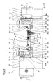
Figure 2 ] is a view showing the outline of the tilt device in the embodiment. - [
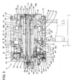
Figure 3 ] is a longitudinal sectional view of a drive device in the tilt device. - [
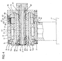
Figure 4 ] is a longitudinal sectional view of a follower device. - [
Figure 5 ] is a flow chart showing a machining program. - Hereafter, a tilt device in an embodiment of the present invention will be described with reference to the drawings. As shown in
Figure 1 , thetilt device 10 is fixed on a work table 11 of a machine tool such as avertical machining center 1 or the like. In themachining center 1, acolumn 3 is provided upright on abed 2, and aspindle head 4 is mounted on thecolumn 3 to be movable in a vertical direction and is moved by a ball screw rotationally driven by aservomotor 5Y. Atool spindle 6 is supported in thespindle head 4 to be rotatable about a vertical axis and is rotationally driven by a built-in motor (not shown). Thetool spindle 6 is provided with a tool attaching device which detachably holds a tool T inserted into a tool attaching hole formed at a lower end of thetool spindle 6. On thebed 2, asaddle 7 is mounted to be movable in a horizontal forward-rearward direction and is moved in a Z-axis direction by a ball screw which is rotationally driven by aservomotor 5Z. On thesaddle 7, the work table 11 is mounted to be movable in a horizontal left-right direction and is moved in an X-axis direction by a ball screw which is rotationally driven by aservomotor 5X. Thecolumn 3 is provided thereon with atool magazine 8 for storing a plurality of tools T and for indexing a tool T to be used next to a tool change position and antool changer 9 for changing the next tool indexed to the tool change position with a used tool T which remains attached in thetool spindle 6 upon completion of a machining. - As shown in
Figure 2 , thetilt device 10 is provided with adrive device 13 secured to the work table 11 for rotationally driving adrive spindle 12 about a pivot axis O, afollower device 15 secured to the work table 11 in face-to-face relation with thedrive device 13 and supporting afollower spindle 14 rotatably about the pivot axis O, a tilt table 17 secured at opposite ends thereof respectively to an extreme end of thedrive spindle 12 and an extreme end of thefollower spindle 14 and attaching to an upper surface thereofjigs 16 which hold a workpiece W, and alift device 19 for lowering a workpiece W, loaded by a loading/unloading device (not shown), in a temporal supporting state to position the workpiece W by fitting reference holes provided on the workpiece W on reference pins provided on the jigs.Distributors jigs 16 and the like are provided on the axes of thedrive spindle 12 and thefollower spindle 14. - As shown in
Figure 3 , thedrive device 13 has afirst support pedestal 20 rotatably supporting thedrive spindle 12 through a front bearing 23 and a rear bearing 24 and secured to the work table 11. Thefirst support pedestal 20 is composed of afront support section 21 which is provided at an upper part thereof with a cylindrical portion rotatably supporting thedrive spindle 12 and which is provided at a lower part thereof with a leg portion secured to the work table 11, and a cylindricalrear support section 22 which rotatably supports a rear end portion of thedrive spindle 12 and which is secured to a cylindrical portion of thefront support section 21. - In the
front support section 21, there are formed a front bearing outer race bore 28 and a retention bore 29 which fit therein an outer race of thefront bearing 23 and astator 26 of adirect drive motor 25. In therear support section 22, there is formed a rear bearing outer race bore 30 which fits therein an outer race of the rear bearing 24. Thestator 26 is fitted in the retention bore 29, and a plurality of bolts 31 (fixing means) which are inserted in the axial direction from a front end surface of thefront support section 21 around the outside of the outer race of thefront bearing 23 are screw-fixed into a front end surface of thestator 26, whereby that thestator 26 is pressed against abottom step portion 32 of the retention bore 29. In therear support section 22, bolts 33 (fixing means) inserted from a rear end surface of therear support section 22 in the axial direction are screw-fixed into a rear end surface of thestator 26, and thus, a front end surface of afitting portion 22a which protrudes from therear support section 22 to be fitted in the retention bore 29 is pressed against the rear end surface of thestator 26, whereby therear support section 22 is secured to thefront support section 21. Between the rear end surface of thefront support section 21 and a shoulder surface which radially extends from a base end of thefitting portion 22a of therear support section 22, a spacer 34 whose thickness is adjusted on the basis of an on-site adjustment is interposed to be in contact with the rear end surface of thefront support section 21 as well as with the shoulder surface of therear support section 22.Seal members 35 are interposed between opposite end surfaces of the spacer 34 and the rear end surface of thefront support section 21 and the shoulder surface of therear support section 22 to fluid-tightly isolate the interior from the exterior. Thus, thefront support section 21, thestator 26 of thedirect drive motor 25 and therear support section 22 are united fluid-tightly and rigidly with the space reduced in radial directions, and thestator 26 is fixedly fitted in the retention bore 29 which is formed in thefirst support pedestal 20 between thefront bearing 23 and the rear bearing 24 coaxially of the pivot axisO. A socket 65 for wiring to thedirect drive motor 25 is fluid-tightly attached to therear support section 22. - The
drive spindle 12 has alarge diameter portion 12a, an intermediate portion 12b and asmall diameter portion 12c formed in turn thereon, and thedrive spindle 12 is supported in thefirst support pedestal 20 to be precisely rotatable about the pivot axis O with thelarge diameter portion 12a fitted in an inner race of thefront bearing 23 and with thesmall diameter portion 12c fitted in an inner race of the rear bearing 24. Therotor 27 of thedirect drive motor 25 andannular members 36a, 36b are fitted on the intermediate diameter portion 12b of thedrive spindle 12. Theannular member 36a is prevented with a key 37a from rotation relative to the intermediate diameter portion 12b and is secured by means ofbolts 38a to a front end surface of therotor 27. The annular member 36b is prevented with a key 37b from rotation relative to the intermediate diameter portion 12b and is secured by means of bolts 38b to a rear end surface of therotor 27. Theannular member 36a is pressed against a step portion between thelarge diameter portion 12a and the intermediate portion 12b by being screw-fixed by means of bolts 39 (fixing means) which are inserted from the front end surface of thedrive spindle 12 through thelarge diameter portion 12a between thedistributor 18 and thefront bearing 23. - The front end of the
drive spindle 12 has aflange 12d formed at a forward part of thelarge diameter portion 12a, and anoil seal 61 is interposed between a large diameter portion internal surface of a stepped bore of an attachingmember 60 secured to the front end surface of thefront support section 21 and an external surface of theflange 12d and is held by anannular retention member 62 secured to a front end of the attachingmember 60, in the large diameter portion of the stepped bore of the attachingmember 60. Theretention member 62 is formed with a labyrinth at a small diameter portion internal surface of the stepped bore formed on the internal surface of theretention member 62 and is fitted on theflange 12d with a slight clearance. The large diameter portion of the stepped bore formed in theretention member 62 defines an annular air purge chamber 63 between a rear surface side of theretention member 62 and the front surface side of theoil seal 61. Anair passage 64 connected to a compressed air supply for the factory is holed in thefront support section 21, and theair passage 64 opens to the air purge chamber 63. Accordingly, the compressed air flown into the air purge chamber 63 through theair passage 64 is flown outside through the labyrinth at the small diameter portion internal surface of the stepped bore in theretention member 62, so that it is possible to prevent cutting lubricant or the like from entering the inside of thedrive device 13. - A
nut 40 is screw-fixed on a rear end portion of thesmall diameter portion 12c of thedrive spindle 12 and is pressed against the inner race of the rear bearing 24 through aring member 41 to adjust a preload exerted on thefront bearing 23 and the rear bearing 24. Thering member 41 is fitted on thesmall diameter portion 12c and is prevented with a key 42 from rotation with amagnet 44 of arotational angle sensor 43 secured to an outer circumference thereof. Adetection section 45 of therotational angle sensor 43 is secured to an opening end surface of the rear bearing outer race bore 30 of therear support section 22 through anannular member 46 and faces themagnet 44. Asocket 66 for wiring to therotational angle sensor 43 is fluid-tightly attached to therear support section 22. - A stepped cylinder bore 47 is formed at a rear end portion of the
rear support section 22 on the pivot axis O, and a front small diameter portion and a large diameter portion of a steppedpiston 48 are respectively fitted on a small diameter portion and a large diameter portion of the stepped cylinder bore 47. Acap member 49 is secured to the rear end surface of therear support section 22, and an external surface and an internal surface of an annular protrudingportion 49a which annually protrudes from the front end surface of thecap member 49 are respectively fitted in the large diameter portion of the stepped cylinder bore 47 and a rear small diameter portion of the steppedpiston 48. Then, a clampingring 51 of aclamping device 50 is secured at a bottom surface of the small diameter bore of the stepped cylinder bore 47. Anannular plate 52 is arranged between an end surface of the front small diameter portion of the steppedpiston 48 and an end surface of the clampingring 51, and theannular plate 52 is secured at a flange portion thereof to the rear end portion of thedrive spindle 12 through a thinflexible portion 52a thereof. In this way, theannular plate 52 is coaxially secured to the rear end of thedrive shaft 12 not to be relatively rotatable but to be relatively movable in the direction of the pivot axis. - The stepped cylinder bore 47 is partitioned by the large diameter portion of the stepped
piston 48 into front and rear cylinder chambers 47a, 47b, which are connected to a pressurized oil source through a change-over valve (not shown). The supply of pressurized oil to the front cylinder chamber 47a causes the steppedpiston 48 to be retracted, whereby theannular plate 52 is released from the clampingring 51 to make thedrive spindle 12 rotatable. The supply of pressurized oil to the rear cylinder chamber 47b causes the steppedpiston 48 to be advanced, whereby theannular plate 52 is pressed against the clampingring 51 to restrict the rotation of thedrive spindle 12 with the oil pressure. - A plurality of compression springs 53 are interposed between an inside end surface of the
cap member 49 and a rear end surface of the steppedpiston 48, and the steppedpiston 48 is urged forward by means of resilient forces of the compression springs 53. Thus, even in the state that the operation of thetilt device 10 is stopped, theannular plate 52 is pressed against the clampingring 51 by means of the resilient forces of the compression springs 53 to restrict the rotation of thedrive spindle 12. - Two
screw shafts 54 extending in the direction of the pivot axis O are engaged with the steppedpiston 48, and anut 57 is screw-engaged with eachscrew shaft 54 outside of thecap member 49. When theclamping device 50 is to be released manually, thescrew shafts 54 and hence, the steppedpiston 48 are retracted against the resilient forces of the compression springs 53 by rotating the nuts 57 in the state that the same are in contact with an outside end surface of thecap member 49, and this causes theannular plate 52 to be released from the clampingring 51, whereby thedrive spindle 12 becomes rotatable. Thescrew shafts 54 engaged with the steppedpiston 48, the nuts 57 and the like constitute retraction means for retracting the steppedpiston 48 against the resilient forces of the compression springs 53. - A stationary-
side member 55 of thedistributor 18 is secured to thecap member 49 on the pivot axis O and passes through a small diameter portion of anaxis hole 12e of thedrive spindle 12 to extend to the vicinity of the front end of thedrive spindle 12. A rotary-side member 56 of thedistributor 18 is secured to the front end surface of thedrive spindle 12 to extend rearward on the axis, is fitted in a large diameter portion of theaxis hole 12e of thedrive spindle 12 and is fitted at adistribution hole 56a thereof on the external surface of the stationary-side member 55. Six stationaryfluid passages 58 for example are holed at a circumferentially equiangular interval to extend in the direction of the pivot axis O, sixannular grooves 55a are formed on the external surface of the stationary-side member 55 at axially different positions in thedistribution hole 56a, and respective stationaryfluid passages 58 are bent to communicate with the respectiveannular grooves 55a. In the rotary-side member 56, six rotaryfluid passages 59 are holed at a circumferentially equiangular interval to extend in the direction of the pivot axis O, and rear ends of the respective rotaryfluid passages 59 are in communication with the respective stationaryfluid passages 58 by being bent to open in thedistribution hole 56a in face to face relation with the respectiveannular grooves 55a. Front ends of the respective rotaryfluid passages 59 open on a front end surface of the rotary-side member 56 which is formed to be a flat surface even with the front end surface of thedrive spindle 12. - As shown in
Figure 2 , since anangle rest 86 of an L-letter shape is secured to the front end of thedrive spindle 12 with its attachingsurface 86a being in contact with thefront end surface 12f of thedrive spindle 12, angle restfluid passages 87 which are holed in theangle rest 86 to open on the attachingsurface 86a communicate with the rotaryfluid passages 59 which open on the front end surface of the rotary-side member 56 of thedistributor 18. Two angle restfluid passages 87 are in communication with upper andlower chambers 95a, 95b of acylinder device 94 which vertically moves a holdingarm 98 of thejig 16 attached to the tilt table 17. Two stationaryfluid passages 58 communicating with these two rotaryfluid passages 59 are connected to the pressurized oil supply device or an oil tank through a change-over valve. Thus, a hydraulic circuit for supplying and discharging pressurized oil with respect to thecylinder device 94 which vertically moves the holdingarm 98 can be constructed easily and to be compact. - Further, as shown in
Figures 2 and3 , a cuttinglubricant hole 67 connected to a cutting lubricant supply device through a shutoff valve passes on the axis of the stationary-side member 55 and opens at a front end opening portion of thedistribution hole 56a of the rotary-side member 56. Thus, with theangle rest 86 fixed to the front end of thedrive spindle 12, one anglerest fluid passage 87 opens to the front end opening portion of thedistribution hole 56a of the rotary-side member 56 and communicates with the cutting lubricant supply device. This one anglerest fluid passage 87 is connected to a cuttinglubricant nozzle 100 which supplies cutting lubricant toward areference surface 92a and the like in order to wash away chips adhered to such a reference surface of thejig 16. Further, the aforementioned one anglerest fluid passage 87 is connected to cutting lubricant nozzles which supply cutting lubricant toward portions of thejig 16 on which chips are liable to be accumulated or spaces or the like between a workpiece W and thejig 16 on which chips are liable to be accumulated, to wash away the chips. - As shown in
Figure 4 , thefollower device 15 has asecond support pedestal 70 rotatably supporting thefollower spindle 14 through afront bearing 71 and arear bearing 72 and secured on the work table 11. In thesecond support pedestal 70, a cylindrical portion rotatably supporting thefollower spindle 14 is formed at an upper part thereof, and a leg portion secured to the work table 11 is formed at a lower part thereof. At the upper part of thesecond support pedestal 70, a bearing bore 73 is formed to pass through the upper part on the pivot axis O, and outer races of thefront bearing 71 and therear bearing 72 are closely fitted in the bearing bore 73 to be movable in the axial direction. - Inner races of the
front bearing 71 and therear bearing 72 are fitted on thefollower spindle 14, and thefollower spindle 14 is supported in thesecond support pedestal 70 to be precisely rotatable about the pivot axis O. Aflange 14a is formed at a front end of thefollower spindle 14, and anoil seal 75 is interposed between a large diameter portion internal surface of a stepped bore of an attaching member 74 secured to a front end surface of thesecond support pedestal 70 and an external surface of theflange 14a and is retained in the large diameter portion of the stepped bore of the attaching member 74 by anannular retention member 76 secured to a front end of the attaching member 74. Theretention member 76 has a labyrinth formed on a small diameter portion internal surface of a stepped bore formed at an internal surface thereof and is fitted on theflange 14a with a slight clearance therebetween. An annularair purge chamber 77 is formed at a large diameter portion of the stepped bore formed in theretention member 76 between a rear surface side of theretention member 76 and a front surface side of theoil seal 75. Anair passage 78 connected to the compressed air supply of the factory is holed in thesecond support pedestal 70, and theair passage 78 opens to theair purge chamber 77. Accordingly, the compressed air flowing into theair purge chamber 77 through theair passage 78 flows outside through the labyrinth at the small diameter portion internal surface of the stepped bore of theretention member 76, so that cutting lubricant or the like can be prevented from entering the inside of thefollower device 15. - A
nut 79 is screw-fixed on a rear end portion of thefollow spindle 14 and is pressed against the inner race of therear bearing 72 through a ring member 80 which is fitted on thefollower spindle 14 to be prevented by a key from rotation, so that a preload on thefront bearing 71 and therear bearing 72 can be adjusted. - A clamping
member 120 is secured at itsflange portion 121 to the rear end portion of thesecond support pedestal 70 by means of bolts, and acap member 84 which fluid-tightly closes a rear end opening portion of thesecond support pedestal 70 is secured to a rear end surface of theflange portion 121 by means of bolts. A clampingportion 122 extending forward of the clampingmember 120 is fitted in the bearing bore 73 of thesecond support pedestal 70 and is fitted on an external surface of the ring member 80 with a play of a slight clearance. An annular clampingoil chamber 123 is formed on an external surface of the clampingportion 122, and O-rings 124 are interposed between the external surface and the bearing bore 73 at opposite sides of the clampingoil chamber 123. When pressurized oil is supplied to the clampingoil chamber 123, a bottom portion of the clampingoil chamber 123 is flexed to be brought into press contact with the external surface of the ring member 80 to restrict the rotation of thefollower spindle 14. The clampingportion 122 and the clampingoil chamber 123 of the clampingmember 120, the ring member 80 and the like constitute aclamping device 125 for thefollower spindle 14. Theclamping device 125 restricts the rotation of thefollower spindle 14 when pressurized oil is supplied to the clampingoil chamber 123, but releases thefollower spindle 14 when the pressurized oil in the clampingoil chamber 123 is discharged. - A numeral 81 denotes the distributor on the
follower device 15 side, and a cylindrical rotary-side member 82 of thedistributor 81 is closely fitted in an axis hole 14b of thefollower spindle 14 and is secured at a front end flange portion thereof to a front end surface of thefollower spindle 14. A stationary-side member 83 of thedistributor 81 is secured to thecap member 84 on the pivot axis O and extends to the vicinity of the front end of thefollower spindle 14 with itself fitted in adistribution hole 82a of the rotary-side member 82. Twelve stationaryfluid passages 84 are holed in the stationary-side member 83 at a circumferentially equiangular interval to extend in the direction of the pivot axis O, while twelveannular grooves 83a are formed on an external surface of the stationary-side member 83 at axially different positions in thedistribution hole 82a, wherein the respective stationaryfluid passages 84 are bent to communicate with the respectiveannular grooves 83a. Twelve rotaryfluid passages 85, for example, are holed in the rotary-side member 82 at a circumferentially equiangular interval to extend in the direction of the pivot axis O, and rear ends of the respective rotaryfluid passages 85 communicate with respective stationaryfluid passages 84 by being bent to open in thedistribution hole 82a in face to face relation with the respectiveannular grooves 83a. Front ends of the respective rotaryfluid passages 85 open on a front end surface of the rotary-side member 82 which is formed to be flat even with the front end surface of thefollower spindle 14. - As shown in
Figures 2 and4 , since an angle rest 88 of an L-letter shape is secured to the front end of thefollower spindle 14 with its attaching surface 88a being in contact with thefront end surface 14f of thefollower spindle 14, angle restfluid passages 89 which are holed in the angle rest 88 to open on the attaching surface 88a communicate with the rotaryfluid passages 85 which open on the front end surface of the rotary-side member 82 of thedistributor 81. Two angle restfluid passages 89 are in communication with upper andlower chambers 95a, 95b of acylinder device 94 which vertically moves a holdingarm 98 of thejig 16 attached to the tilt table 17. Two stationaryfluid passages 84 communicating with these two rotaryfluid passages 85 are connected to the pressurized oil supply device or the oil tank through the change-over valve. - Further, the compressed air supply and a pressure detection device are connected in parallel to one
stationary fluid passage 84, and arotary fluid passage 85 communicating with this onestationary fluid passage 84 is connected through communication with the anglerest fluid passage 89 to anair nozzle 130 opening on areference surface 92d of thejig 16, so that there is constituted a seating detection device for detecting that the workpiece W is seated on thereference surface 92d. A cuttinglubricant hole 68 connected to the cutting lubricant supply device through the shutoff valve is also formed to pass on the axis of the stationary-side member 83 and like the cuttinglubricant hole 67 on the drive spindle side, supplies the reference surface with cutting lubricant to wash away chips adhered to the reference surface of thejig 16, so that cutting lubricant is supplied toward portions of thejig 16 on which chips are liable to be accumulated or spaces or the like between the workpiece W and thejig 16 on which chips are liable to be accumulated, to wash away the chips. - Support surfaces 86b, 88b parallel to the pivot axis O are formed on the angle rests 86, 88 to extend in a direction perpendicular to the pivot axis O, and the tilt table 17 taking the shape of a plate is secured by means of
bolts 99 to the support surfaces 86b, 88b in contact with the same at a back surface thereof. Since the tile table 17 is secured with its back surface being in contact with the support surfaces 86b, 88b of the angle rests 86, 88,table fluid passages fluid passages fluid passages side members distributors table fluid passages lubricant nozzles 100 which supply cutting lubricant toward thereference surfaces reference surfaces jigs 16.Figure 2 shows the cuttinglubricant nozzle 100 only which supplies cutting lubricant toward thereference surface 92a. Further, the angle restfluid passages table fluid passages jigs 16 on which chips are liable to be accumulated, or the spaces or the like between the workpiece W and thejigs 16 on which chips are liable to be accumulated, to wash away the chips. Furthermore, the angle restfluid passages distributors table fluid passages air nozzles 130 which open on the references surfaces 92a, 92d of thejigs 16 for detecting that the workpiece W is seated on thereference surfaces Figure 2 shows theair nozzle 130 only which opens to thereference surfaces 92d. - On the tilt table 17, the
lift device 19 is provided for temporarily supporting on a temporal support table 101 the workpiece W loaded by the loading/unloading device (not shown) and for vertically moving the workpiece W. A pair of guidedrods 102 protruding downward are secured to a lower surface of the temporal support table 101 and are slidably fitted inguide members 103 secured to the tilt table 17. Acylinder device 104 is secured to the lower surface of the tilt table 17, and apiston rod 105 of thecylinder device 104 passes through the tilt table 17 to be secured to the temporal support table 101. - A
numerical controller 90 relatively moves thespindle head 4 rotatably supporting thetool spindle 6 and the work table 11 with the workpiece W detachably attached thereto to machine the workpiece W with a tool T attached to thetool spindle 6 by rotationally controlling theservomotors machining center 1, thedirect drive motor 25 of thetilt device 10 and the like and controls the relative angular position between the tool T and the workpiece W by rotating thedrive spindle 12 and hence, the tilt table 17. Further, thenumerical controller 90 separates thespindle head 4 and the work table 11 for a predetermined period of time in the course of the machining of the workpiece W with the tool T by rotationally controlling theservomotors machining center 1 and, by rotating thedirect drive motor 25 of thetilt device 10 at a high speed, rotates thedrive spindle 12 and the tilt table 17 at such a high speed as, e.g., 50 rpm or higher, preferably 200 rpm or so to shake out chips and coolant accumulated on the workpiece W, the tilt table 17 and the like. - Next, the operation of the foregoing embodiment will be described. The
numerical controller 90 executes a machining program shown inFigure 5 and machines the workpiece W with the tool T. When having an unfinished workpiece W mounted thereon by the loading/unloading device, the temporal support table 101 is moved downward by thecylinder device 104 and inserts the reference holes provided on the workpiece W on the reference pins 93a, 93b provided on the tilt table 17 to position the workpiece W in a workpiece mounting plane and to place the workpiece W on thereference surfaces lubricant nozzle 100 through the cuttinglubricant hole 67, the anglerest fluid passage 87 and thetable fluid passage 90 to wash away chips adhered to thereference surface 92a of thejig 16. Chips adhered to thereference surface 92d are washed away in the same manner. - When electric power is inputted (step S1), the shutoff valve is opened to make compressed air flow into the
air purge chambers 63, 77 through theair passages retention members drive device 13 and the follower device 15 (step S2). When the workpiece W is placed on thereference surfaces respective cylinders 95 through thedistributors arms 98 are moved downward by therespective cylinder devices 94 to press the upper surface of the workpiece W toward thereference surfaces jigs 16. The seating of the workpiece W on the reference surfaces is confirmed because it is detected by the pressure detection device that theair nozzles 130 opening on thereference surfaces - After it is confirmed that the workpiece W is seated on the
reference surfaces jigs 16, if the setting of the relative angular position between the tool T and the workpiece W is required to be changed, theclamping devices drive spindle 12 and thefollower spindle 14, thedrive spindle 12 is rotated by thedirect drive motor 25 to rotate the tilt table 17 relative to thetool spindle 6, and thereafter, theclamping devices drive spindle 12 and the follower spindle 14 (step S4). That is, the change-over valve is switched to supply pressurized oil to the front cylinder chamber 47a, while the rear cylinder chamber 47b is brought into communication with the tank. Thus, the steppedpiston 48 is retracted against the resilient forces of the compression springs 53, and theannular plate 52 is separated from the clampingring 51 to release theclamping device 50, whereby thedrive spindle 12 becomes rotatable. At the same time, pressurized oil is discharged from the clampingoil chamber 123, and the bottom portion of the clampingoil chamber 123 is retracted from the external surface of the ring member 80 to make thefollower spindle 14 rotatable. Thereafter, thedirect drive motor 25 is driven to rotate therotor 27, and thedrive spindle 12 is rotated through theannular members 36a, 36b secured to the front and rear end surfaces of therotor 27 and thekeys drive spindle 12, namely that the tilt table 17 has been rotated to a desired angular position is detected by therotational angle sensor 43, thedirect drive motor 25 is stopped, and the change-over valve is switched to supply the rear cylinder chamber 47b with pressurized oil and to make the front cylinder chamber 47a communicate with the tank. As a result, the steppedpiston 48 is advanced, and theclamping device 50 is brought into operation with theannular plate 52 pressed against the clampingring 51 to restrict the rotation of thedrive spindle 12 by a pressurized oil force. At the same time, the clampingoil chamber 123 is supplied with pressurized oil, and the bottom portion of the clampingoil chamber 123 is flexed and pressed against the external surface of the ring member 80 to restrict the rotation of thefollower spindle 14. Therefore, it does not occur that the tilt table 17 is rotationally moved due to a cutting force. - Then, the
servomotors spindle head 4 and thesaddle 7, and thus, thetool spindle 6 being rotationally driven and the work table 11 are moved relatively, whereby the workpiece W is machined with the tool T attached to the tool spindle 6 (step S5). While the workpiece W is being machined with the tool T, cutting lubricant is supplied from the cutting lubricant nozzles toward the portions of thejigs 16 on which chips are liable to be accumulated, or the spaces or the like between the workpiece W and thejigs 16 on which chips are liable to be accumulated, to wash away the chips. - Upon completion of the machining with the first tool T, in order to perform a tool change, the
servomotors spindle head 4 and thetool spindle 6 to a tool change position, and the work table 11 and thesaddle 7 are moved to move the work table 11 away from thespindle head 4. Thetool magazine 8 is rotationally indexed so that a next tool T to be used next is presented to the tool change position. Thetool changer 9 grips the tool T attached to thetool spindle 6 having been positioned to the tool change position and the next tool presented by thetool magazine 8 to the tool change position, and pulls the both tools T out of thetool spindle 6 and thetool magazine 8, and after a turn through an angle of 180 degrees, goes back to attach the next tool T to thetool spindle 6 and to return the used tool T to the tool magazine 8 (step S6). - Within a tool change time while the tool T attached to the
tool spindle 6 is changed by thetool changer 9 and in the state that thespindle head 4 and the work table 11 are kept away, thedirect drive motor 25 is rotated at a high speed only in a predetermined period of time to rotate thedrive spindle 12 and hence, the tilt table 17 at a high speed (step S7). Therefore, without elongating the cycle time and within the time period for automatic change for the tools T, it is possible to shake out chips and coolant which would cause an adverse affect on the machining with the next tool, from on the workpiece W and the tilt table 17. - Upon the attachment of the next tool T to the
tool spindle 6, the steps S2-S5 are repeated, so that the same operations are thereafter repeated until the machining with all of tools T necessary for the machining of the workpiece W is completed (step S8). Accordingly, in particular, where a workpiece W is machined by the use of many tools T, it does not take place that chips and coolant are accumulated on the workpiece W and the like, and when all of machining is completed, it is sufficient to shake out the chips generated during the machining with the last tool T and coolant, so that it becomes possible to easily take out the workpiece W in the state that the same does not have chips and coolant adhered thereto. Accordingly, it is possible to maintain clean a conveyor for transferring workpieces W between machining centers, and further, it can be prevented that the accurate positioning of a workpiece having been loaded to a machining center at a next step is obstructed by the intervention of chips between references surfaces and the workpiece W. - Generally, since in vertical machining centers, chips and coolant are liable to be accumulated on a workpiece, it may usually be the case that horizontal machining centers are chosen at sacrifices of a cost aspect and a space aspect. According to the
present tilt device 10, since it does not occur that chips and coolant are accumulated on the workpiece W, it can be realized to choose and arrange right vertical machining centers in right places. - In the
drive device 13 according to the present embodiment, for example, if the power supply is turned off after completion of works, the steppedpiston 48 is advanced by the resilient forces of the compression springs 53, and theannular plate 52 is pressed against the clampingring 51 to restrict the rotation of thedrive spindle 12. Therefore, it does not occur that the tilt table 17 is turned suddenly due to a weight imbalance. - Further, because it is possible to retract the
screw shafts 54 and hence, the steppedpiston 48 against the resilient forces of the compression springs 53 by rotating the nuts 57 in contact with the outside end surface of thecap member 49, it is possible to easily rotate thedrive spindle 12 even in the state that thetilt device 10 is out of operation, and it is possible for example to easily perform the attaching/detaching of the tilt table 17 or the maintenance and the like of the peripheries of thedrive spindle 12. - In the foregoing embodiment, within the tool change period of time during which a tool T attached to the
tool spindle 6 is changed by thetool changer 9 with a next tool, the tilt table 17 is rotated by thedirect drive motor 25 only in a predetermined period of time with thespindle head 4 and the work table 11 kept away. However, for example, where the machining with one tool takes a long time, thespindle head 4 and the work table 11 may be spaced away only for a predetermined period of time in the course of such machining, and the tilt table 17 may be rotated by thedirect drive motor 25 at a high speed. - Although in the foregoing embodiment, the tilt device is constituted by arranging the
drive device 13 and thefollower device 15 in face to face relation, the tilt device may be constituted by arranging two drive devices in face to face relation, wherein direct drive motors may be operated synchronously. Further, the tilt device may be constituted by onedrive device 13 only. - A tilt device according to the present invention is suitable to be used as a tilt device which is equipped on a machine tool and which controls the relative angular position between a tool and a workpiece by rotating a tilt table by a direct drive motor.
- 1...machining center, 2...bed, 3...column, 4...spindle head, 5X, 5Y, 5Z...servomotors, 6...tool spindle, 7...saddle, 8...tool magazine, 9...tool changer, 10...tilt device, 11...work table, 12...drive spindle, 13...drive device, 14...follower spindle, 15...follower device, 16...jigs, 17...tilt table, 18...distributor, 20...first support pedestal, 21...front support section, 22...rear support section, 23...front bearing, 24...rear bearing, 25...direct drive motor, 26...stator, 27...rotor, 28...front bearing outer race bore, 29...retention bore, 30...rear bearing outer race bore, 31, 33, 38, 39...bolts, 34...spacer, 43...rotational angle sensor, 49...cap member, 50, 125...clamping devices, 55...stationary-side member, 56...rotary-side member, 70...second support pedestal, 71...front bearing, 72...rear bearing.
Claims (6)
- A tilt device secured onto a work table of a machine tool wherein a spindle head rotatably supporting a tool spindle and the work table to which a workpiece is detachably attached are relatively moved to machine the workpiece with a tool attached to the tool spindle, the tilt device being characterized by comprising:a support pedestal secured on the work table;a drive spindle supported by a front bearing and a rear bearing in the support pedestal rotatably about a pivot axis;a distributor provided on the axis of the drive spindle for distribution of pressurized oil;a direct drive motor provided with a stator fixedly fitted in a retention bore which is formed coaxially of the pivot axis between the front bearing and the rear bearing in the support pedestal and a rotor fixedly fitted on the drive spindle;a tilt table secured to the drive spindle for detachably attaching the workpiece thereto; anda controller for controlling the relative angular position between the tool and the workpiece by rotating the drive spindle by the operation of the direct drive motor and for rotating the tilt table at a high speed to shake out chips by rotating the direct drive motor at a high speed with the spindle head and the work table kept away in a predetermined period of time in the state that the workpiece is attached on the tilt table.
- A tilt device secured onto a work table of a machine tool wherein a spindle head rotatably supporting a tool spindle and the work table to which a workpiece is detachably attached are relatively moved to machine the workpiece with a tool attached to the tool spindle, the tilt device being characterized by comprising:a support pedestal secured on the work table;a drive spindle having a large diameter portion, an intermediate diameter portion and a small diameter portion formed in turn and supported at the large diameter portion and the small diameter portion by a front bearing and a rear bearing in the support pedestal to be rotatable about a pivot axis;a distributor provided on the axis of the drive spindle for distribution of pressurized oil;a direct drive motor provided with a stator fixedly fitted in a retention bore which is formed coaxially of the pivot axis between the front bearing and the rear bearing in the support pedestal, and a rotor fitted on the intermediate diameter portion of the drive spindle;an annular member fitted on the intermediate diameter portion of the drive spindle to be prevented by a key from rotation and secured to a front end surface of the rotor;fixing means inserted in an axial direction from a front end surface of the drive spindle through the large diameter portion between the distributor and the front bearing and pressing the annular member against a stepped portion between the large diameter portion and the intermediate diameter portion;a tilt table secured to the drive spindle; anda controller for controlling the relative angular position between the tool and the workpiece by rotating the drive spindle by the operation of the direct drive motor and for rotating the tilt table at a high speed to shake out chips by rotating the direct drive motor at a high speed with the spindle head and the work table kept away within a predetermined period of time in the course of machining the workpiece.
- The tile device described in Claim 2, characterized in that:the support pedestal is composed of a front support section secured to the base and having formed a front bearing outer race bore and the retention bore fitting therein an outer race of the front bearing and the stator of the direct drive motor and a rear support section having formed a rear bearing outer race bore fitting therein an outer race of the rear bearing and secured to the front support section;the stator is pressed against a bottom stepped portion of the retention bore by fixing means which are inserted in an axial direction from the front end surface of the front support section around the outer diameter of the outer race of the front bearing, and a front end surface of a fitting portion which is protruded from the rear support section to fit in the retention bore is pressed against a rear end surface of the stator by fixing means which are inserted in the axial direction from a rear end surface of the rear support section, whereby the rear support section is secured to the front support section; andbetween a rear end surface of the front support section and a shoulder surface radially extending from a base end of the fitting portion of the rear support section, a spacer is interposed fluid-tightly in contact with the rear end surface of the front support section and the shoulder surface of the rear support section.
- The tile device described in Claim 3, characterized in that:the distributor is provided with a stationary-side member secured to a cap member secured to the rear end surface of the rear support section and extending on the axis of the drive spindle and a rotary-side member secured to the front end surface of the drive spindle to extend on the axis of the drive spindle and fitted at a distribution hole on the stationary-side member;a plurality of stationary fluid passages connected externally are holed in the stationary-side member; anda plurality of rotary fluid passages which respectively communicate with the plurality of stationary fluid passages in the distribution hole open on a front end surface of the rotary-side member which is formed to be a flat surface even with the front end surface of the drive spindle.
- The tile device described in any one of Claims 1 to 4,
characterized by comprising:a clamping ring secured to the rear end surface of the support section on the pivot axis;an annular plate coaxially secured to a rear end of the drive spindle to be restricted from relative rotation but to be relatively movable in the direction of the pivot axis;a cylinder device for press-contacting or releasing the annular plate with the clamping ring;a compression spring urging a piston of the cylinder device to bring the annular plate into press contact with the clamping ring; andretraction means for retracting the piston against the resilient force of the compression spring. - The tile device described in any one of Claims 1 to 5, characterized in that the predetermined period of time is set within a tool change period of time during which the machine tool changes a tool attached to the tool spindle by a tool changer.
Applications Claiming Priority (2)
| Application Number | Priority Date | Filing Date | Title |
|---|---|---|---|
| JP2008302421A JP5371394B2 (en) | 2008-11-27 | 2008-11-27 | Tilt device |
| PCT/JP2009/069445 WO2010061749A1 (en) | 2008-11-27 | 2009-11-16 | Tilt device |
Publications (3)
| Publication Number | Publication Date |
|---|---|
| EP2353776A1 true EP2353776A1 (en) | 2011-08-10 |
| EP2353776A4 EP2353776A4 (en) | 2012-05-09 |
| EP2353776B1 EP2353776B1 (en) | 2013-01-23 |
Family
ID=42225627
Family Applications (1)
| Application Number | Title | Priority Date | Filing Date |
|---|---|---|---|
| EP09828997A Not-in-force EP2353776B1 (en) | 2008-11-27 | 2009-11-16 | Tilt device |
Country Status (8)
| Country | Link |
|---|---|
| US (1) | US8672819B2 (en) |
| EP (1) | EP2353776B1 (en) |
| JP (1) | JP5371394B2 (en) |
| KR (1) | KR101114705B1 (en) |
| CN (1) | CN101918173B (en) |
| BR (1) | BRPI0906479B1 (en) |
| ES (1) | ES2403455T3 (en) |
| WO (1) | WO2010061749A1 (en) |
Families Citing this family (17)
| Publication number | Priority date | Publication date | Assignee | Title |
|---|---|---|---|---|
| JP6380190B2 (en) * | 2015-03-27 | 2018-08-29 | ブラザー工業株式会社 | Machine Tools |
| JP6306544B2 (en) | 2015-08-11 | 2018-04-04 | ファナック株式会社 | Machine tool cleaning system |
| JP6514271B2 (en) | 2017-06-16 | 2019-05-15 | ファナック株式会社 | Rotary table device |
| JP6564437B2 (en) | 2017-09-06 | 2019-08-21 | ファナック株式会社 | Rotary table system |
| JP6362751B1 (en) * | 2017-09-15 | 2018-07-25 | 株式会社松浦機械製作所 | Cutting oil supply method |
| TWI664365B (en) * | 2017-12-29 | 2019-07-01 | 財團法人工業技術研究院 | Ball screw with tilt detector |
| JP6878386B2 (en) * | 2018-12-10 | 2021-05-26 | ファナック株式会社 | Cleaning equipment, cleaning methods and machine tools |
| JP7344658B2 (en) * | 2019-03-18 | 2023-09-14 | コマツNtc株式会社 | Work support device |
| JP7354628B2 (en) * | 2019-07-10 | 2023-10-03 | 株式会社ジェイテクト | Tooth groove machining device |
| CN110429755B (en) * | 2019-07-27 | 2024-05-10 | 巨力自动化设备(浙江)有限公司 | Motor rotation swing mechanism |
| JP6752346B1 (en) * | 2019-10-08 | 2020-09-09 | 株式会社スギノマシン | washing machine |
| CN112621261B (en) * | 2021-01-15 | 2022-11-01 | 西安钜宸科技有限公司 | Modular electrostatic worktable is prevented in machining |
| CN114985788B (en) * | 2022-06-20 | 2023-08-01 | 陈豪 | Intelligent manufactured numerical control machine tool clamping device |
| CN115179348A (en) * | 2022-07-04 | 2022-10-14 | 昆山美厚绝缘材料有限公司 | Continuous blanking device of battery insulating piece |
| CN116060667B (en) * | 2022-12-26 | 2023-07-21 | 深圳市建筑装饰(集团)有限公司 | Angle adjusting platform for decorative material processing drilling machine |
| CN116833776B (en) * | 2023-06-29 | 2024-09-17 | 安徽通湾科技有限公司 | High-precision numerical control metal cutting machine tool |
| CN116833813B (en) * | 2023-07-11 | 2023-12-22 | 湖北毅兴智能装备股份有限公司 | Double-spindle structure of four-axis gang tool lathe |
Family Cites Families (15)
| Publication number | Priority date | Publication date | Assignee | Title |
|---|---|---|---|---|
| US3738226A (en) * | 1970-11-20 | 1973-06-12 | Tampa Brass & Aluminum Corp | Thread cutting attachment for lathes |
| US4705438A (en) * | 1986-08-20 | 1987-11-10 | Wesflex International Corporation | Machining center having an inclinable vacuum-holding worktable |
| FR2664084B1 (en) * | 1990-06-27 | 1993-07-16 | Framatome Sa | METHOD AND DEVICE FOR DISMANTLING AN IRRADIATED COMPONENT OF A NUCLEAR REACTOR BY MACHINING ITS WALL. |
| JPH09300151A (en) | 1996-05-13 | 1997-11-25 | Toshiba Mach Co Ltd | Tilting work table device for machine tool |
| JP2001009653A (en) * | 1999-06-30 | 2001-01-16 | Toyoda Mach Works Ltd | Tilt device |
| JP2002079431A (en) * | 2000-09-07 | 2002-03-19 | Ishikawajima Harima Heavy Ind Co Ltd | Flat plate finishing machine |
| WO2002092277A2 (en) * | 2001-05-15 | 2002-11-21 | Paul Müller Gmbh & Co. Kg | Motor spindle with improved machining precision and method for operating one such motor spindle |
| JP2003260631A (en) * | 2002-03-04 | 2003-09-16 | Enshu Ltd | Machine tools with chip compression processing equipment |
| CN2584346Y (en) * | 2002-10-31 | 2003-11-05 | 广东巨轮模具股份有限公司 | Special linear cutting machine tool |
| JP4354722B2 (en) | 2003-03-27 | 2009-10-28 | 住友重機械工業株式会社 | Clamp device and vertical drive positioning device with tilt function provided with the same |
| JP4732734B2 (en) * | 2004-08-31 | 2011-07-27 | ユキワ精工株式会社 | Rotary table device |
| EP1839806B1 (en) * | 2006-03-27 | 2009-04-29 | Fanuc Ltd | Automatic tool changing method and device for machine tool controlled by numerical controller |
| JP5072269B2 (en) * | 2006-06-16 | 2012-11-14 | ユキワ精工株式会社 | Rotary table device |
| DE102006034123B4 (en) * | 2006-07-24 | 2009-02-12 | Deckel Maho Seebach Gmbh | Milling and drilling machine and workpiece table arrangement |
| CN201109030Y (en) * | 2007-09-13 | 2008-09-03 | 北京精雕科技有限公司 | Inclinable numerical control rotating table |
-
2008
- 2008-11-27 JP JP2008302421A patent/JP5371394B2/en active Active
-
2009
- 2009-11-16 ES ES09828997T patent/ES2403455T3/en active Active
- 2009-11-16 WO PCT/JP2009/069445 patent/WO2010061749A1/en not_active Ceased
- 2009-11-16 US US12/745,792 patent/US8672819B2/en not_active Expired - Fee Related
- 2009-11-16 KR KR1020107014688A patent/KR101114705B1/en not_active Expired - Fee Related
- 2009-11-16 CN CN2009801016911A patent/CN101918173B/en not_active Expired - Fee Related
- 2009-11-16 BR BRPI0906479-6A patent/BRPI0906479B1/en not_active IP Right Cessation
- 2009-11-16 EP EP09828997A patent/EP2353776B1/en not_active Not-in-force
Non-Patent Citations (2)
| Title |
|---|
| No further relevant documents disclosed * |
| See also references of WO2010061749A1 * |
Also Published As
| Publication number | Publication date |
|---|---|
| WO2010061749A1 (en) | 2010-06-03 |
| KR20100090801A (en) | 2010-08-17 |
| BRPI0906479B1 (en) | 2020-10-13 |
| ES2403455T3 (en) | 2013-05-20 |
| EP2353776A4 (en) | 2012-05-09 |
| US20100247262A1 (en) | 2010-09-30 |
| EP2353776B1 (en) | 2013-01-23 |
| JP2010125552A (en) | 2010-06-10 |
| US8672819B2 (en) | 2014-03-18 |
| CN101918173B (en) | 2012-06-20 |
| JP5371394B2 (en) | 2013-12-18 |
| KR101114705B1 (en) | 2012-02-29 |
| CN101918173A (en) | 2010-12-15 |
| BRPI0906479A2 (en) | 2015-07-14 |
Similar Documents
| Publication | Publication Date | Title |
|---|---|---|
| EP2353776B1 (en) | Tilt device | |
| US6178608B1 (en) | Rotary transfer machine | |
| KR20240127599A (en) | Rotary table device of machine tools | |
| JP7025642B2 (en) | lathe | |
| KR20150050255A (en) | Device for testing durability of machining center spindle | |
| US20090250858A1 (en) | Indexing table apparatus | |
| US12472599B2 (en) | Sag compensation apparatus of machine tool and machine tool including same | |
| JP2020019101A (en) | Workpiece tool and workpiece support system provided with the same | |
| CN103547410B (en) | Safety device for rotating feed rod | |
| TW201739568A (en) | Rotary table for machining workpiece | |
| JP5004363B2 (en) | Machining head for machine tools | |
| KR20210155713A (en) | circle manufacturing rotator for index table | |
| KR102536393B1 (en) | Spindle of machine tool | |
| KR20110019599A (en) | Clamping Device of Numerically Controlled Rotary Table | |
| JP6132695B2 (en) | Machine tool table device | |
| JP4304469B2 (en) | Honing machine tool change method and honing machine. | |
| JP5045487B2 (en) | Balancing machine and aligning method thereof | |
| JP4488775B2 (en) | Rotating table of machine tool | |
| CN113146470A (en) | Car cylinder body foundry goods anchor clamps and foundry goods production line of polishing | |
| KR20220124002A (en) | Spindle clamp device | |
| CN215033802U (en) | Four-station robot auxiliary spot facing device of worm-driven left and right axle-holding dividing plate | |
| JP5125420B2 (en) | Workpiece attachment / detachment device | |
| JP4975429B2 (en) | Machining head for machine tool and spindle unit used for machining head | |
| WO2024204355A1 (en) | Table device of machine tool, and machine tool | |
| JP2005088098A (en) | Machining center |
Legal Events
| Date | Code | Title | Description |
|---|---|---|---|
| PUAI | Public reference made under article 153(3) epc to a published international application that has entered the european phase |
Free format text: ORIGINAL CODE: 0009012 |
|
| 17P | Request for examination filed |
Effective date: 20100604 |
|
| AK | Designated contracting states |
Kind code of ref document: A1 Designated state(s): AT BE BG CH CY CZ DE DK EE ES FI FR GB GR HR HU IE IS IT LI LT LU LV MC MK MT NL NO PL PT RO SE SI SK SM TR |
|
| DAX | Request for extension of the european patent (deleted) | ||
| A4 | Supplementary search report drawn up and despatched |
Effective date: 20120410 |
|
| RIC1 | Information provided on ipc code assigned before grant |
Ipc: B23Q 1/64 20060101AFI20120402BHEP Ipc: B23Q 11/00 20060101ALI20120402BHEP Ipc: B23Q 3/155 20060101ALI20120402BHEP Ipc: B23Q 1/52 20060101ALI20120402BHEP |
|
| GRAP | Despatch of communication of intention to grant a patent |
Free format text: ORIGINAL CODE: EPIDOSNIGR1 |
|
| GRAS | Grant fee paid |
Free format text: ORIGINAL CODE: EPIDOSNIGR3 |
|
| GRAA | (expected) grant |
Free format text: ORIGINAL CODE: 0009210 |
|
| AK | Designated contracting states |
Kind code of ref document: B1 Designated state(s): AT BE BG CH CY CZ DE DK EE ES FI FR GB GR HR HU IE IS IT LI LT LU LV MC MK MT NL NO PL PT RO SE SI SK SM TR |
|
| REG | Reference to a national code |
Ref country code: GB Ref legal event code: FG4D |
|
| REG | Reference to a national code |
Ref country code: CH Ref legal event code: EP |
|
| REG | Reference to a national code |
Ref country code: AT Ref legal event code: REF Ref document number: 594682 Country of ref document: AT Kind code of ref document: T Effective date: 20130215 Ref country code: CH Ref legal event code: EP |
|
| RAP2 | Party data changed (patent owner data changed or rights of a patent transferred) |
Owner name: SANKEI C AND C CORPORATION Owner name: SHOHO IRONWORKS CO., LTD. Owner name: TOYOTA JIDOSHA KABUSHIKI KAISHA Owner name: TOKAI KYOHAN CO., LTD. |
|
| REG | Reference to a national code |
Ref country code: IE Ref legal event code: FG4D |
|
| REG | Reference to a national code |
Ref country code: DE Ref legal event code: R096 Ref document number: 602009013104 Country of ref document: DE Effective date: 20130321 |
|
| REG | Reference to a national code |
Ref country code: ES Ref legal event code: FG2A Ref document number: 2403455 Country of ref document: ES Kind code of ref document: T3 Effective date: 20130520 |
|
| REG | Reference to a national code |
Ref country code: AT Ref legal event code: MK05 Ref document number: 594682 Country of ref document: AT Kind code of ref document: T Effective date: 20130123 |
|
| REG | Reference to a national code |
Ref country code: LT Ref legal event code: MG4D |
|
| REG | Reference to a national code |
Ref country code: NL Ref legal event code: VDEP Effective date: 20130123 |
|
| PG25 | Lapsed in a contracting state [announced via postgrant information from national office to epo] |
Ref country code: NO Free format text: LAPSE BECAUSE OF FAILURE TO SUBMIT A TRANSLATION OF THE DESCRIPTION OR TO PAY THE FEE WITHIN THE PRESCRIBED TIME-LIMIT Effective date: 20130423 Ref country code: BG Free format text: LAPSE BECAUSE OF FAILURE TO SUBMIT A TRANSLATION OF THE DESCRIPTION OR TO PAY THE FEE WITHIN THE PRESCRIBED TIME-LIMIT Effective date: 20130423 Ref country code: AT Free format text: LAPSE BECAUSE OF FAILURE TO SUBMIT A TRANSLATION OF THE DESCRIPTION OR TO PAY THE FEE WITHIN THE PRESCRIBED TIME-LIMIT Effective date: 20130123 Ref country code: BE Free format text: LAPSE BECAUSE OF FAILURE TO SUBMIT A TRANSLATION OF THE DESCRIPTION OR TO PAY THE FEE WITHIN THE PRESCRIBED TIME-LIMIT Effective date: 20130123 Ref country code: IS Free format text: LAPSE BECAUSE OF FAILURE TO SUBMIT A TRANSLATION OF THE DESCRIPTION OR TO PAY THE FEE WITHIN THE PRESCRIBED TIME-LIMIT Effective date: 20130523 Ref country code: SE Free format text: LAPSE BECAUSE OF FAILURE TO SUBMIT A TRANSLATION OF THE DESCRIPTION OR TO PAY THE FEE WITHIN THE PRESCRIBED TIME-LIMIT Effective date: 20130123 Ref country code: LT Free format text: LAPSE BECAUSE OF FAILURE TO SUBMIT A TRANSLATION OF THE DESCRIPTION OR TO PAY THE FEE WITHIN THE PRESCRIBED TIME-LIMIT Effective date: 20130123 |
|
| PG25 | Lapsed in a contracting state [announced via postgrant information from national office to epo] |
Ref country code: PL Free format text: LAPSE BECAUSE OF FAILURE TO SUBMIT A TRANSLATION OF THE DESCRIPTION OR TO PAY THE FEE WITHIN THE PRESCRIBED TIME-LIMIT Effective date: 20130123 Ref country code: FI Free format text: LAPSE BECAUSE OF FAILURE TO SUBMIT A TRANSLATION OF THE DESCRIPTION OR TO PAY THE FEE WITHIN THE PRESCRIBED TIME-LIMIT Effective date: 20130123 Ref country code: NL Free format text: LAPSE BECAUSE OF FAILURE TO SUBMIT A TRANSLATION OF THE DESCRIPTION OR TO PAY THE FEE WITHIN THE PRESCRIBED TIME-LIMIT Effective date: 20130123 Ref country code: PT Free format text: LAPSE BECAUSE OF FAILURE TO SUBMIT A TRANSLATION OF THE DESCRIPTION OR TO PAY THE FEE WITHIN THE PRESCRIBED TIME-LIMIT Effective date: 20130523 Ref country code: SI Free format text: LAPSE BECAUSE OF FAILURE TO SUBMIT A TRANSLATION OF THE DESCRIPTION OR TO PAY THE FEE WITHIN THE PRESCRIBED TIME-LIMIT Effective date: 20130123 Ref country code: GR Free format text: LAPSE BECAUSE OF FAILURE TO SUBMIT A TRANSLATION OF THE DESCRIPTION OR TO PAY THE FEE WITHIN THE PRESCRIBED TIME-LIMIT Effective date: 20130424 Ref country code: LV Free format text: LAPSE BECAUSE OF FAILURE TO SUBMIT A TRANSLATION OF THE DESCRIPTION OR TO PAY THE FEE WITHIN THE PRESCRIBED TIME-LIMIT Effective date: 20130123 |
|
| PG25 | Lapsed in a contracting state [announced via postgrant information from national office to epo] |
Ref country code: HR Free format text: LAPSE BECAUSE OF FAILURE TO SUBMIT A TRANSLATION OF THE DESCRIPTION OR TO PAY THE FEE WITHIN THE PRESCRIBED TIME-LIMIT Effective date: 20130123 |
|
| PG25 | Lapsed in a contracting state [announced via postgrant information from national office to epo] |
Ref country code: RO Free format text: LAPSE BECAUSE OF FAILURE TO SUBMIT A TRANSLATION OF THE DESCRIPTION OR TO PAY THE FEE WITHIN THE PRESCRIBED TIME-LIMIT Effective date: 20130123 Ref country code: DK Free format text: LAPSE BECAUSE OF FAILURE TO SUBMIT A TRANSLATION OF THE DESCRIPTION OR TO PAY THE FEE WITHIN THE PRESCRIBED TIME-LIMIT Effective date: 20130123 Ref country code: SK Free format text: LAPSE BECAUSE OF FAILURE TO SUBMIT A TRANSLATION OF THE DESCRIPTION OR TO PAY THE FEE WITHIN THE PRESCRIBED TIME-LIMIT Effective date: 20130123 Ref country code: CZ Free format text: LAPSE BECAUSE OF FAILURE TO SUBMIT A TRANSLATION OF THE DESCRIPTION OR TO PAY THE FEE WITHIN THE PRESCRIBED TIME-LIMIT Effective date: 20130123 Ref country code: EE Free format text: LAPSE BECAUSE OF FAILURE TO SUBMIT A TRANSLATION OF THE DESCRIPTION OR TO PAY THE FEE WITHIN THE PRESCRIBED TIME-LIMIT Effective date: 20130123 |
|
| PG25 | Lapsed in a contracting state [announced via postgrant information from national office to epo] |
Ref country code: CY Free format text: LAPSE BECAUSE OF FAILURE TO SUBMIT A TRANSLATION OF THE DESCRIPTION OR TO PAY THE FEE WITHIN THE PRESCRIBED TIME-LIMIT Effective date: 20130123 |
|
| PLBE | No opposition filed within time limit |
Free format text: ORIGINAL CODE: 0009261 |
|
| STAA | Information on the status of an ep patent application or granted ep patent |
Free format text: STATUS: NO OPPOSITION FILED WITHIN TIME LIMIT |
|
| PG25 | Lapsed in a contracting state [announced via postgrant information from national office to epo] |
Ref country code: IT Free format text: LAPSE BECAUSE OF FAILURE TO SUBMIT A TRANSLATION OF THE DESCRIPTION OR TO PAY THE FEE WITHIN THE PRESCRIBED TIME-LIMIT Effective date: 20130123 |
|
| 26N | No opposition filed |
Effective date: 20131024 |
|
| REG | Reference to a national code |
Ref country code: DE Ref legal event code: R097 Ref document number: 602009013104 Country of ref document: DE Effective date: 20131024 |
|
| REG | Reference to a national code |
Ref country code: CH Ref legal event code: PL |
|
| PG25 | Lapsed in a contracting state [announced via postgrant information from national office to epo] |
Ref country code: LI Free format text: LAPSE BECAUSE OF NON-PAYMENT OF DUE FEES Effective date: 20131130 Ref country code: MC Free format text: LAPSE BECAUSE OF FAILURE TO SUBMIT A TRANSLATION OF THE DESCRIPTION OR TO PAY THE FEE WITHIN THE PRESCRIBED TIME-LIMIT Effective date: 20130123 Ref country code: CH Free format text: LAPSE BECAUSE OF NON-PAYMENT OF DUE FEES Effective date: 20131130 |
|
| REG | Reference to a national code |
Ref country code: IE Ref legal event code: MM4A |
|
| PG25 | Lapsed in a contracting state [announced via postgrant information from national office to epo] |
Ref country code: IE Free format text: LAPSE BECAUSE OF NON-PAYMENT OF DUE FEES Effective date: 20131116 |
|
| PG25 | Lapsed in a contracting state [announced via postgrant information from national office to epo] |
Ref country code: SM Free format text: LAPSE BECAUSE OF FAILURE TO SUBMIT A TRANSLATION OF THE DESCRIPTION OR TO PAY THE FEE WITHIN THE PRESCRIBED TIME-LIMIT Effective date: 20130123 |
|
| PG25 | Lapsed in a contracting state [announced via postgrant information from national office to epo] |
Ref country code: TR Free format text: LAPSE BECAUSE OF FAILURE TO SUBMIT A TRANSLATION OF THE DESCRIPTION OR TO PAY THE FEE WITHIN THE PRESCRIBED TIME-LIMIT Effective date: 20130123 |
|
| PG25 | Lapsed in a contracting state [announced via postgrant information from national office to epo] |
Ref country code: MK Free format text: LAPSE BECAUSE OF FAILURE TO SUBMIT A TRANSLATION OF THE DESCRIPTION OR TO PAY THE FEE WITHIN THE PRESCRIBED TIME-LIMIT Effective date: 20130123 Ref country code: LU Free format text: LAPSE BECAUSE OF NON-PAYMENT OF DUE FEES Effective date: 20131116 Ref country code: HU Free format text: LAPSE BECAUSE OF FAILURE TO SUBMIT A TRANSLATION OF THE DESCRIPTION OR TO PAY THE FEE WITHIN THE PRESCRIBED TIME-LIMIT; INVALID AB INITIO Effective date: 20091116 |
|
| PG25 | Lapsed in a contracting state [announced via postgrant information from national office to epo] |
Ref country code: MT Free format text: LAPSE BECAUSE OF FAILURE TO SUBMIT A TRANSLATION OF THE DESCRIPTION OR TO PAY THE FEE WITHIN THE PRESCRIBED TIME-LIMIT Effective date: 20130123 |
|
| REG | Reference to a national code |
Ref country code: FR Ref legal event code: PLFP Year of fee payment: 7 |
|
| REG | Reference to a national code |
Ref country code: FR Ref legal event code: PLFP Year of fee payment: 8 |
|
| REG | Reference to a national code |
Ref country code: FR Ref legal event code: PLFP Year of fee payment: 9 |
|
| PGFP | Annual fee paid to national office [announced via postgrant information from national office to epo] |
Ref country code: GB Payment date: 20211119 Year of fee payment: 13 Ref country code: FR Payment date: 20211122 Year of fee payment: 13 Ref country code: DE Payment date: 20211118 Year of fee payment: 13 |
|
| PGFP | Annual fee paid to national office [announced via postgrant information from national office to epo] |
Ref country code: ES Payment date: 20220121 Year of fee payment: 13 |
|
| REG | Reference to a national code |
Ref country code: DE Ref legal event code: R119 Ref document number: 602009013104 Country of ref document: DE |
|
| GBPC | Gb: european patent ceased through non-payment of renewal fee |
Effective date: 20221116 |
|
| PG25 | Lapsed in a contracting state [announced via postgrant information from national office to epo] |
Ref country code: GB Free format text: LAPSE BECAUSE OF NON-PAYMENT OF DUE FEES Effective date: 20221116 Ref country code: DE Free format text: LAPSE BECAUSE OF NON-PAYMENT OF DUE FEES Effective date: 20230601 |
|
| PG25 | Lapsed in a contracting state [announced via postgrant information from national office to epo] |
Ref country code: FR Free format text: LAPSE BECAUSE OF NON-PAYMENT OF DUE FEES Effective date: 20221130 |
|
| REG | Reference to a national code |
Ref country code: ES Ref legal event code: FD2A Effective date: 20240102 |
|
| PG25 | Lapsed in a contracting state [announced via postgrant information from national office to epo] |
Ref country code: ES Free format text: LAPSE BECAUSE OF NON-PAYMENT OF DUE FEES Effective date: 20221117 |
|
| PG25 | Lapsed in a contracting state [announced via postgrant information from national office to epo] |
Ref country code: ES Free format text: LAPSE BECAUSE OF NON-PAYMENT OF DUE FEES Effective date: 20221117 |