EP2353440A1 - Fitting for a corner cupboard and corner cupboard - Google Patents
Fitting for a corner cupboard and corner cupboard Download PDFInfo
- Publication number
- EP2353440A1 EP2353440A1 EP11000793A EP11000793A EP2353440A1 EP 2353440 A1 EP2353440 A1 EP 2353440A1 EP 11000793 A EP11000793 A EP 11000793A EP 11000793 A EP11000793 A EP 11000793A EP 2353440 A1 EP2353440 A1 EP 2353440A1
- Authority
- EP
- European Patent Office
- Prior art keywords
- fitting
- clamping
- support column
- tray
- jaw
- Prior art date
- Legal status (The legal status is an assumption and is not a legal conclusion. Google has not performed a legal analysis and makes no representation as to the accuracy of the status listed.)
- Granted
Links
- 238000003780 insertion Methods 0.000 claims description 6
- 230000037431 insertion Effects 0.000 claims description 6
- 238000006073 displacement reaction Methods 0.000 claims description 5
- 238000013016 damping Methods 0.000 description 14
- 239000006096 absorbing agent Substances 0.000 description 9
- 230000035939 shock Effects 0.000 description 9
- 238000011161 development Methods 0.000 description 4
- 230000018109 developmental process Effects 0.000 description 4
- XEEYBQQBJWHFJM-UHFFFAOYSA-N Iron Chemical compound [Fe] XEEYBQQBJWHFJM-UHFFFAOYSA-N 0.000 description 2
- 238000005452 bending Methods 0.000 description 2
- 230000006978 adaptation Effects 0.000 description 1
- 238000013459 approach Methods 0.000 description 1
- 239000003795 chemical substances by application Substances 0.000 description 1
- 229910052742 iron Inorganic materials 0.000 description 1
- 210000003734 kidney Anatomy 0.000 description 1
- 239000000463 material Substances 0.000 description 1
- 239000002184 metal Substances 0.000 description 1
- 229910052751 metal Inorganic materials 0.000 description 1
- 125000006850 spacer group Chemical group 0.000 description 1
- 210000002105 tongue Anatomy 0.000 description 1
Images


Classifications
-
- A—HUMAN NECESSITIES
- A47—FURNITURE; DOMESTIC ARTICLES OR APPLIANCES; COFFEE MILLS; SPICE MILLS; SUCTION CLEANERS IN GENERAL
- A47B—TABLES; DESKS; OFFICE FURNITURE; CABINETS; DRAWERS; GENERAL DETAILS OF FURNITURE
- A47B49/00—Revolving cabinets or racks; Cabinets or racks with revolving parts
- A47B49/004—Cabinets with compartments provided with trays revolving on a vertical axis
- A47B49/006—Corner cabinets
-
- A—HUMAN NECESSITIES
- A47—FURNITURE; DOMESTIC ARTICLES OR APPLIANCES; COFFEE MILLS; SPICE MILLS; SUCTION CLEANERS IN GENERAL
- A47B—TABLES; DESKS; OFFICE FURNITURE; CABINETS; DRAWERS; GENERAL DETAILS OF FURNITURE
- A47B81/00—Cabinets or racks specially adapted for other particular purposes, e.g. for storing guns or skis
- A47B81/002—Corner cabinets; Cabinets designed for being placed in a corner or a niche
Definitions
- the invention relates to a fitting for a corner cabinet, in particular causaleck O, with a cabinet body and accessible via a corner door interior, in which a support column is arranged with a longitudinal axis, wherein in the interior of the cabinet body at least one tray by means of the fitting between an inner position and an outer position in which the tray protrudes at least partially beyond a plane of a door opening, is movably guided, and wherein the fitting can be fastened to the support column by means of a fastening device.
- a fitting of this kind is for example from the DE 20 2004 011 200 U1 known, in which a respective tray of two articulated on its underside of the handlebars is supported, wherein the first link is pivotable about a pivot axis of a support column and the second link about an axis parallel to the pivot axis of the support column axis of a support bearing.
- the tray is controlled by both handlebars together between the inner and the outer position.
- the Tablarterrorism takes place here by superimposition of two each executed around the respective pivot axes orbits. Ultimately, this results in a between the inner and outer position of the tray performed S-shaped tabla movement.
- a handlebar to the support column is by means of a bearing bush is performed, which is rotatably supported on the support column, wherein the height position can be determined by a transverse pin, which passes through a corresponding transverse bore in the support column.
- the handlebar is supported rotatably with a bearing eye attached to the handlebar end.
- a stepless height adjustment of the handlebar along the support column is not possible. It can only be set certain predetermined by the transverse bores in the support column altitudes.
- the object of the invention is therefore to provide a fitting of the type mentioned, which can be fixed at any altitude along the support column.
- the fitting according to the invention is characterized in that the fastening device comprises a clamping piece with clamping means which are adjustable between a fitting on the support column in the desired height relative to the support column immovably clamped clamping position and a continuous height adjustment of the fitting along the support column enabling release position.
- the fitting is displaceable in any position along the support column and there by means of the clamping piece immovably clamped to the support column.
- the support column itself has no facilities that would be necessary to attach the fitting to her, in contrast to the transverse bores in the support column from the DE 20 2004 011 200 U1 ,
- the clamping piece is part of the fitting.
- the clamping means comprise two relatively movable jaws, with which the associated support column can at least partially surround and define the attachment of the clamping piece to the support column in the release position an insertion, the cross section is greater than the cross section of the support column.
- a rigidly arranged on the clamping piece and a relatively movable second clamping jaw is provided for this purpose.
- both jaws movable for example in the form of a jaw gripper.
- the second clamping jaw is mounted by means of pivoting means about a jaw pivot axis pivotally mounted on the clamping piece.
- the second jaw is mounted linearly displaceable by means of guide means in the axial direction to the longitudinal axis of the support column, wherein at the same time an axially aligned clamping surface of the jaw in the radial direction inwardly to the rigid first jaw is to be displaced.
- the guide means may comprise at least one guide bevel running obliquely to the longitudinal axis and a sliding surface cooperating therewith and extending in particular parallel to the longitudinal axis.
- the movable jaw can so wedge slide on this sliding surface, whereby a displacement of the clamping surface in the radial direction is achieved inward.
- the guide bevel is located on the jaw, in particular the clamping surface opposite.
- the second jaw has two each having a guide bevel jaw members, which are mounted in the axial direction to the pivot axis by means of actuating means relative to each other movable on the clamping piece, wherein in a Auffactzu movement, a displacement of the clamping surfaces takes place radially inward.
- the adjusting means may comprise a set screw passing through the jaw members.
- the fitting has at least one arm pivotally mounted on the tray on the one hand to a stationary pivot axis and on the other hand on a tablarfesten bearing axes for Tablarabstützung and a control device for inflation of Tablarterrorism in the pivot plane between the inner and outer position.
- the control device may have two control levers, which are each mounted on the one hand about a stationary pivot axis and on the other hand about a tablarfeste bearing axis with respect to this rotatable and immovable.
- the two stationary pivot axes can be arranged adjacent to one another or coincide.
- a connecting member is provided for connecting the two control levers, which receives the two tablarfesten bearing axes of the control lever and in turn is attached to the tray.
- one of the two control levers at the same time forms the support arm and is in the form of a combined control / support lever, which has a greater bending stiffness relative to the other control lever perpendicular to the pivot plane.
- the invention further relates to a corner cabinet with the features of independent claim 16.
- the corner cabinet according to the invention is characterized in that the fastening device comprises a clamping piece with clamping means which are adjustable between a fitting to the support column in the desired height relative to the support member immovably clamped clamping position under a continuous height adjustment of the fitting along the support column enabling release position.
- FIGS. 1 and 2 show a first embodiment of the invention Eck Os 11 and the built-in inventive fitting 12.
- the corner cabinet 11 has a cabinet body 13, which is shown by way of example with a rectangular plan.
- the cabinet body 13 in turn consists of a rear wall 14, two side walls 15, 16 and a front side 17, which in turn is subdivided into a front wall 18 and a corner cabinet door 19 arranged adjacent thereto FIGS. 21 to 23 shows, the corner door 19 is seen from the front on the right side of the front side 17 and the front wall 18 correspondingly arranged on the left side of the front side 17.
- the extension movement of the tray thus takes place in a clockwise direction.
- the corner cabinet door 19 can alternatively also be arranged on the left side of the front side 17 of the corner cabinet 11, so that the extension movement of the shelf from the inside position takes place by pivoting in the counterclockwise direction.
- Front wall 18 and corner door 19 occupy the front 17 in approximately equal parts.
- the rectangular cabinet body 13 defines a correspondingly rectangular interior 21, which is accessible in about half of the corner cabinet door 19.
- the interior of the corner cupboard 11 is at least one tray 22, which is housed by means of the fitting 12 between an inner position in which the tray 22 is completely housed in the interior 21, and an outer position in which the tray 22 at least partially over a plane 23 of a door opening the corner cupboard 11 protrudes, is movably controlled in a pivoting plane.
- a single tray 22 is shown here.
- two or more superimposed shelves 22 are arranged.
- the tray 22 is exemplified in one-piece embodiment.
- the floor plan of the tray 22 is exemplified in the form of a kidney.
- the tray 22 has on its front wall 18 facing the inside of a sidecut 24 to allow a comfortable swinging out of the interior 21 and pivoting into the interior 21 without the tray 22 on the front wall 18 abuts or remains hanging.
- the fitting 12 has at least one pivotally mounted on the one hand to a fixed in the installed state of the tray 22 pivot axis 25 and on the other hand on a tablarfesten bearing axis 26 pivotally mounted on the associated tray supporting arm for Tablarabstützung and a control device for controlling the Tablarterrorism in the pivoting plane between the indoor and the external position.
- the control device further has two control levers, one of which also forms the support arm and is designed in the form of a combined control / support lever 27, which has a greater bending stiffness relative to the other control lever 28 at right angles to the pivot plane.
- the control / support lever thus performs a double function, so he controls the tablet movement between the inner and outer position as a control lever and supports the tray 22 as a support arm.
- the control lever 28 is also mounted on the one hand to a fixed pivot axis 29 and on the other hand to a tablarfeste bearing axis 30 with respect to this rotatable and immovable.
- the control / support lever 27 is mounted about its tablarfeste bearing axis 26 with respect to this rotatable and immovable.
- the two stationary pivot axes 25, 29 of the control / support lever 27 and the control lever 28 are adjacent to each other or fall together, wherein in the illustrated embodiments, by way of example, an adjacent arrangement of the stationary pivot axes 25, 29 is shown.
- this is formed by a metal square tube.
- a bearing sleeve 31 is fixed to the stationary end of this square tube, in particular welded.
- a bearing pin for example in the form of a rivet inserted through which in turn is attached to a U-shaped, the bearing sleeve 31 receiving bearing portion 33 on a clamping piece 34 described in more detail below.
- the bearing pin forms the stationary pivot axis 25 about which the control / support lever 27 is pivotally mounted.
- a further bearing sleeve 35 is fastened in a similar manner, in particular welded.
- the bearing sleeve 35 is penetrated by a bearing pin, which in turn is mounted on a connecting member 36 described in more detail below.
- the bearing pin thus forms the tablarfeste bearing axis 26 of the control / support lever 27th
- control lever 28 is formed by a flat iron bar.
- control lever 18 has at both opposite ends in each case a particular circular passage opening 37, in each of which a bearing pin, for example in the form of a rivet, is inserted therethrough.
- the one end of the control lever 28 is in turn mounted on the clamping piece 34, wherein the bearing pin forms the stationary pivot axis 29 of the control lever 28.
- the opposite end is mounted by means of the other bearing pin on the connecting member 36, said bearing pin forms the tablarfeste bearing axis 30 of the control lever 28.
- both tablarfesten bearing shafts 26, 30 of the control / support lever 27 and the control lever 28 are arranged on a connecting member 36 which thus connects these two tablarfesten bearing shafts 26, 30 together.
- the connecting member 36 has an axle carrier 40, on which the two tablarfesten bearing shafts 26, 30 are mounted in the previously described manner.
- the axle carrier 40 is designed yoke-like and has a plate-like first stub axle 41a and a plate-like second stub axle 41b extending parallel thereto, which are held at a distance from each other via two spacers 42 in the form of material webs. Between the two stub axles 41a, 41b is located on the control / support lever 27 end side bearing sleeve 31. In contrast, the control lever 28 is mounted only on one of the two stub axles 41a, 41b by means of the tablarfeste bearing axis 30 forming the bearing pin.
- the connecting member 36 also has an elongated support arm 43, which is also designed as a square tube.
- Support arm 43 and axle carrier 40 are rigidly connected to each other, for example, can be welded together.
- the most rigid bearing axes form this 26, 30 on the axle carrier 40 a connecting line 44 which is obtuse angled to a longitudinal axis 45 of the support arm 43 ( FIG. 8 ).
- the axle 40 In the fastened state of the fitting 12 on the shelf bottom 46 of the tray 22 is the axle 40 with the two tablarfesten bearing axes 26, 30 in one, formed by a central transverse axis 47 tray half 48, while the support arm 43 in the other of the two tray halves 48 protrudes.
- the support arm 43 exercises next to the control / support lever 27 a support function for supporting the tray 22. It prevents the tray 22 is supported only on a tray half 48, which could result in instabilities, especially when standing on the tray items. In this case, a large moment would be exerted on the attachment between the axle 40 and the tray, which could lead to a release of the axle carrier 40 from the tray 22.
- the support arm 43 On the support arm 43 at least one fastening tab 49 is provided, via which the support arm 43 can be attached to the tray bottom 46.
- the mounting tab 49 is located on the support arm end, which is opposite to the axle support 40.
- the corner cupboard 11 further has the already mentioned supporting column 39 with a longitudinal axis 38.
- the support column 39 is fastened to the cabinet bottom 20 via a bearing plate 50 and is free in the cabinet body 13, that is not with the side walls 15, 16 and front wall 18 and rear wall 14 connected.
- a further bearing plate 51 is attached, via which the support column 39 is mounted on a cabinet cover (not shown).
- the support column 39 is designed as a telescopic column and has for this purpose a column base 52 and a linearly displaceable in the column base 52 mounted telescopic part 53. The telescoping of the support column 39 allows their adaptation to different Eck O cannot be used.
- the fitting 12 is fixed by means of a fastening device to the support column 39.
- a fastening device includes the aforementioned clamping piece 34 or bearing element has the clamping means which between a fitting 12 to the support column 39 at the desired height relative to the support column 39 immovably clamped clamping position 54 and a continuous height adjustment of the fitting along the support column 39 enabling release position 55 adjustable are.
- the base body 56 has a base body 56 and two relatively movable jaws 57, 58, with which the associated support column 39 can at least partially surround.
- the U-shaped bearing portion 33 On the base body 56 is the U-shaped bearing portion 33, in which the bearing sleeve 31 of the control / support lever 27 is received, and by means of the stationary pivot axis 25 forming the bearing pin is pivotally mounted.
- One of the legs of the bearing part 33 is designed plate-like and has the passage opening 37, on which by means of the stationary pivot axis 29 forming bearing pin of the control lever 28 is pivotally mounted. It is possible that this plate-like leg has a plurality of such passage openings, so that the stationary pivot axis 29 can be implemented, whereby the pivot radius of the control lever 28 and its position to the control / support lever 27 can be changed.
- one of the two clamping jaws 57 is thus arranged so as to be immovable on the main body 56.
- FIGS. 13 to 16 show a first embodiment of the clamping piece 34 according to which the rigid clamping jaw 57 is configured like a hook.
- the second jaw 58 is movably arranged relative to the rigid jaw 57, with the two jaws in the in FIG. 15 or 16 shown release position 55 define an insertion opening 59, with which the clamping piece 34 can be attached laterally to the support sleeve 39, so that the two jaws 57, 58 surround the circumference of the support column 39 partially.
- the rigid clamping jaw 57 is configured like a hook.
- the second jaw 58 is movably arranged relative to the rigid jaw 57, with the two jaws in the in FIG. 15 or 16 shown release position 55 define an insertion opening 59, with which the clamping piece 34 can be attached laterally to the support sleeve 39, so that the two jaws 57, 58 surround the circumference of the support column 39 partially.
- this insertion opening 59 is narrowed so far that removal of the clamping piece 34 obliquely to the longitudinal axis 38 of the support column 39 is no longer possible and also a clamping of the clamping piece 54 is present on the support column 39, so that this is fixed relative to the support column 39 immovable , Conveniently, the clamping of the clamping piece 34 is carried on the column bottom 52 of the support column 39th
- the movable second jaw 58 is mounted according to the first embodiment by means of guide means in the axial direction to the longitudinal axis 38 of the support column 39 linearly displaceable, wherein at the same time an axially aligned clamping surface of the jaw 58 in the radial direction inwardly to the rigid first jaw is to be displaced.
- the movable jaw 58 has two jaw members 61a, 61b, which are mounted relative to each other in the axial direction to the longitudinal axis 38 of the support column 39 movable relative to each other on the base body 56 of the clamping piece 34, wherein in a Auffactzu movement a displacement of the clamping surfaces on the jaw members 61a, 61b takes place radially inward.
- the part of Guiding agents are.
- the guide slopes 62a, 62b cooperate with a sliding surface 63 which is formed by a substantially parallel to the longitudinal axis of the support column 39 aligned wall on the base body 56.
- the guide bevels 62a, 62b of the jaw members 61a, 61b are inclined towards each other, ie when the jaw members 61a, 61b move together, an ever-increasing cross-section of the jaw members 61a, 61b slides on the sliding face 63, whereby the clamping surfaces 60a, 60b move radially inside to the first jaw 57 to be moved.
- adjusting means in the form of an adjusting screw 64 passing through the two jaw members 61a, 61b are used FIG. 15 shown, the adjusting screw 64 is additionally stored in a bearing web 65 of the body.
- the two jaws 57, 58 are first brought into the release position 55, wherein the two jaw members 61a, 61b are moved away from each other. This can be done by unscrewing the screw 34. This results in an insertion opening 59, whose cross section is larger than the cross section of the support column 39, so that the clamping piece 34 can be attached laterally to the support column 39. After setting the screw 64 is screwed again, whereby the two jaw members 61a, 61b are moved towards each other.
- FIGS. 17 to 20 show a second embodiment of the clamping piece 34.
- a rigid, fixed first jaw 57 and a relatively movable second jaw 58 is provided for this purpose.
- the rigid jaw 57 has a larger jaw height than the movable jaw 58.
- the movable second jaw 58 is pivotally mounted by means of pivot means 66 about a jaw pivot axis 67 on the base body 56 of the clamping piece 34.
- the pivot means are configured in a similar manner as in the pivotable mounting of the control / support lever 27 or the control lever 28.
- the pivoting jaw 58 is mounted for this purpose in a U-shaped bearing mount, wherein a pivot bearing pin through both the bearing receiving limiting bearing leg 68a, 68b and the jaw 58 is passed.
- locking means are provided in the form of a locking screw, which is preferably in the transverse direction to the jaw pivot axis 67 aligned both jaws 57, 58 passes and mounted on the rigid jaw 58.
- the two clamping jaws 57, 58 are first brought into the release position 55 by unscrewing the locking screw 69. This creates an in FIG. 19 or 20 shown insertion opening 59 whose cross section is greater than the cross section or diameter of the support column 39, so that the clamping piece 34 can be attached laterally to the support column. If the desired altitude of the clamping piece 34 is reached on the support column 39, the locking screw 69 is screwed, whereby the pivotally movable clamping jaw 58th is pivoted toward the rigid clamping jaw 57 until it finally presses with clamping force on the outside of the support column 39, whereby a clamping of the clamping piece on the support column 39 is formed.
- the clamping piece 34 can be infinitely adjustable in height at any point along the support column, in principle also be clamped to the telescope part 53.
- the fitting 12 is to be attached to the shelf bottom 46 of the tray 22.
- mounting interfaces 70 are formed on the tray bottom 46, which serve for fastening of the fitting 12 by means of the fastening interfaces 70 corresponding fitting-side interface means 71.
- a plurality of fastening interfaces 70 form an interface pattern 72, which is designed such that the fitting 12 can be fastened in two different fastening positions on the shelf 22, so that depending on the predetermined fastening position clockwise or alternatively counterclockwise from the inner to the outer position is pivotable.
- the attachment interfaces 70 are configured as attachment holes in which interface means in the form of fasteners, such as screws, rivets or the like, which are previously passed through corresponding through holes in the fitting 12, can be fixed.
- the Interface means 71 formed by the fastening tab 49 attached to the support arm 43, which has two through holes for the passage of fasteners in the form of mounting screws, which in turn are fixed in the corresponding mounting interfaces 70 on the tray bottom 46.
- the interface means 71 still include the bearing pin, which forms the most rigid bearing axis 26 of the control / support lever 27. This protrudes through the two stub axles 41a, 41b of the axle carrier 40 and projects upwards so that it can be fixed in the corresponding attachment interface 70.
- the bearing pin that forms the tabletopest bearing axis 30 of the control lever 28 also belongs to the interface means 71. This is guided through a passage opening formed in both stub axles 41a, 41b and protrudes from the top side of the axle carrier 40, so that it engages in its corresponding attachment interface 70 the tray bottom 46 can be inserted and fixed there.
- FIG. 2 shows the interface pattern 72 according to the first embodiment distributed over a large area on the tray bottom 46.
- the half of the mounting interfaces 70 of this interface pattern is located on one tray half 48, while the other half is located on the other tray half.
- a center longitudinal axis 73 is defined, the center longitudinal axis being the X axis and the center transverse axis being the Y axis, the tray 22 is divided into four quadrants the attachment interfaces of this interface pattern 72 are then distributed over all four quadrants.
- four different interface groups 74a, 74b, 74c, 74d are shown here two attachment interfaces 70 are provided in each case.
- the interface groups 74a-d are here mirror-symmetrical to the Y-axis in an exemplary manner.
- Two of the interface groups 74a, 74c are located in the region of the rear edge of the tray, wherein the two attachment interfaces 70 of these interface groups 74a, 74c are arranged one behind the other in the X direction.
- the two other interface groups 74b, 74d are located approximately halfway between the outer side edge of the tray 22 and the Y-axis, with the mounting interfaces 70 of these interface groups 74b, 74d arranged one behind the other in the Y direction.
- the support arm 43 When mounting the fitting 12 according to the first embodiment, the support arm 43 is attached with its fastening tab on the aligned in the Y direction interface group 74b on one tray half 48 and fastened by means of the fastening screws.
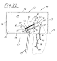
- the axle carrier 40 with its bearing pin or bearing pin is attached to the aligned in the X direction interface group 74c on the other tray half and fastened there. This attachment results in a tabla movement according to the FIGS. 21 to 23 , The corner cabinet door 19 is thus seen from the front on the right side and the tray 22 pivots clockwise out of the corner cabinet 11 out.
- the fitting 12 and thus the tray 22 in opposite directions, ie swing out of the interior 21 in the counterclockwise direction. This would then be the corner cupboard door 11 on the left side arranged.
- the fitting 12 is this folded over by 180 ° and the fastening tab 49 on the support arm 43 is attached to the other opposite sides of the support arm 43.
- the support arm 43 with its fastening tab 49 then protrudes into the tray half 48, in which the axle carrier 40 was placed in the other fastening position, while the axle carrier 40 now projects into the tray half 48 in which the support arm 43 with its fastening tab 49 was previously positioned ,
- the fastening tab 49 is then fastened again to the Y-directional interface group 74d with the aid of the fastening screws, while the axle support 40 with the bearing bolts or pins is then fastened to the other panel half 48 in the X direction aligned interface group 74a is attached.
- the tray 22 can thus swing out of the interior 21 either left or right as needed.
- FIGS. 4 and 5 show a second embodiment of the fitting 12 according to the invention, which differs from the first embodiment described above in that the interface pattern 72 is configured differently and also other interface means 71 are used.
- the mounting interfaces 70 are in all four defined by the X and Y axis quadrants on the tray bottom 46. In contrast to the aforementioned embodiment, however, all mounting interfaces 70 are used here in two different mounting positions of the fitting 12 through the associated interface means. By way of example, four fastening interfaces 70 are provided here.
- the interface means 71 comprise an adapter plate 75 which is releasably secured to the top of the square tube-like support arm 43.
- the adapter plate 75 has through holes 76, for example, corresponding to the number of mounting interfaces 70 four in number. Fastening elements, for example fixing screws, are inserted through the through-holes 76 and fixed in the corresponding fastening interfaces 70 on the tray underside 46.
- On the adapter plate 75 are expediently in the longitudinal direction between two through holes 76 centering in the form of upwardly above the top of the adapter plate 75 projecting centering 77, which in corresponding centering holes 78 on the tray bottom 46, which expediently also in the X direction between two mounting interfaces 70th are arranged, can be introduced.
- the adapter plate can position accurately positioned, whereby the aligned position between the through holes 76 on the adapter plate 75 and the mounting interfaces 70 is reached automatically.
- the second embodiment is suitable in a simple manner for an opposing pivoting out of the tray 22 from the interior 21.
- the fitting 12 is again folded over by 180 ° and the adapter plate 75 attached to the opposite side of the support arm 43.
- again all mounting interfaces 70 are used and the adapter plate 75 is attached to the tray bottom 46 at the same location as before. Again, so the tray 22 can swing out as needed left or right around, the corner door is then located either on the left or right side.
- FIGS. 5 to 7 show further embodiments of interface patterns 72 that differ from the interface patterns described above.
- Tabla shown are arranged on the tray bottom mounting interfaces 70, for example, ten in number, which are arranged mirror-symmetrically to the X-axis.
- FIG. 6 shows a variant of the interface pattern 72 of FIG. 5
- the mounting interfaces 70 are aligned both mirror-symmetrical to the X-axis and mirror-symmetrical to the Y-axis.
- FIG. 7 a further variant in which the attachment interfaces, for example, also ten in number, are aligned mirror-symmetrically to the Y-axis.
- the fitting 12 also has an entry and exit device 79 to support the retraction and extension of the tray in the indoor and outdoor position.
- the entry and exit device 79 has a spring unit 80, which is mounted on the one hand at a stationary spring bearing 81 and the other on a movable in the Tablarterrorism movable bearing 82 such that on the fitting 12, a retraction assisting torque in the direction of the inner position and after exceeding a dead center, the outward movement supporting torque is exerted in the direction of the outer position.
- the spring unit 18 is formed by a tension spring in the form of a helical tension spring.
- the stationary spring-bearing point 81 is located on the clamping piece 34 and that on the extended plate-like Leg on which the stationary pivot axis 29 of the control lever 28 is seated.
- the moving in the Tablarterrorism bearing 82 is located on the control lever 28, in particular approximately in the middle between the fixed pivot axis 29 and the tablarfesten bearing axis 30th
- the fixed pivot axis and the movable bearing 82 of the spring on the control lever 28 define a straight line with respect to which the fixed spring bearing 81 in the support of the retraction on one side and in supporting the extension movement on the other side.
- the stationary pivot axis 28 and the fixed spring bearing 81 are spaced from each other and that on one side by the fixed pivot axis of the control lever 28 and the movable bearing point the spring unit 80 formed straight lines.
- a torque is applied counterclockwise to the control lever 28 and thereby to the tray 22, so that the tray 22 is held by the spring unit 80 defined in the inner position. If the tray 22 is now pivoted out of the interior 21 in a clockwise direction, this force must first be overcome in the retraction direction in order to pivot the tray 22. When swinging out the tray 22 then reaches an intermediate position by the stationary pivot axis 29 of the control lever 28 and the stationary spring bearing 81 are in line, so that no torque is applied.
- the damping device 83 for damping the Tablarterrorism when retracting to the inner position and / or extending into the outer position.
- the damping device 83 has a shock absorber 84, which is arranged such that it damps both when approaching the inner position and when approaching the outer position and is ineffective in at least one intermediate position between the inner and the outer position.
- the shock absorber 84 is in accordance with FIGS. 8 to 10 shown in exemplary arrangement on the control / support lever 27. There it sits approximately in the middle between the stationary pivot axis 25 and the tablarfesten pivot axis 26 of the control / support lever 27.
- the shock absorber 84 is formed by a damping cylinder, with a cylinder housing 85 in which a damping piston 86 is guided linearly displaceable.
- control lever 28 On the control lever 28 are two arranged at different positions stop surfaces 87a, 87b, which cooperate with the damping piston 86 such that when approaching the inner position of a damping stop of shock absorber 84 and a stop surface 87a and when approaching the outer position of a damping stop of shock absorbers 84th and the other abutment surface 87b is present.
- One and the same Shock absorber 84 thus dampens both when approaching the inner position and when approaching the outer position.
- the two end positions of the tray 22, ie the inner and the outer position, are damped.
- the fitting 12 and the tray 22 are thus initially in the in FIG. 8
- the stop surface 87a which is formed by the outer contour of the control lever 28, presses on the damping piston 86 of the shock absorber 84. If the tray then, for example, as in FIG. 9 shown pivoted out of the corner cabinet 11 in the clockwise direction, so move control / support lever 27 and control lever 28 relative to each other, whereby the damping piston 86 out of contact with the stop surface 87a, whereby the shock absorber 84 is ineffective. If the tray is now pivoted further into the outward position, the damping piston 86 comes into contact with the other stop surface 87b formed on the stop member 88 as it approaches this outward position, thus damping the retraction into the outward position.
Abstract
Description
Die Erfindung betrifft einen Beschlag für einen Eckschrank, insbesondere Kücheneckschrank, mit einem Schrankkorpus und einem über eine Eckschranktür zugänglichen Innenraum, in dem eine Tragsäule mit einer Längsachse angeordnet ist, wobei im Innenraum des Schrankkorpus wenigstens ein Tablar mittels des Beschlags zwischen einer Innenstellung und einer Außenstellung, in der das Tablar zumindest teilweise über eine Ebene einer Türöffnung hinaussteht, beweglich geführt ist, und wobei der Beschlag mittels einer Befestigungsvorrichtung an der Tragsäule befestigbar ist.The invention relates to a fitting for a corner cabinet, in particular Kücheneckschrank, with a cabinet body and accessible via a corner door interior, in which a support column is arranged with a longitudinal axis, wherein in the interior of the cabinet body at least one tray by means of the fitting between an inner position and an outer position in which the tray protrudes at least partially beyond a plane of a door opening, is movably guided, and wherein the fitting can be fastened to the support column by means of a fastening device.
Ein Beschlag dieser Art ist beispielsweise aus der
Eine stufenlose Höhenverstellung des Lenkers entlang der Tragsäule ist nicht möglich. Es können nur bestimmte, durch die Querbohrungen in der Tragsäule vorgegebene Höhenlagen eingestellt werden.A stepless height adjustment of the handlebar along the support column is not possible. It can only be set certain predetermined by the transverse bores in the support column altitudes.
Aufgabe der Erfindung ist es daher, einen Beschlag der eingangs erwähnten Art zu schaffen, der sich in beliebiger Höhenlage entlang der Tragsäule befestigen lässt.The object of the invention is therefore to provide a fitting of the type mentioned, which can be fixed at any altitude along the support column.
Diese Aufgabe wird durch einen Beschlag mit den Merkmalen des unabhängigen Anspruchs 1 gelöst. Weiterbildungen der Erfindung sind in den Unteransprüchen dargestellt.This object is achieved by a fitting with the features of the independent claim 1. Further developments of the invention are shown in the subclaims.
Der erfindungsgemäße Beschlag zeichnet sich dadurch aus, dass die Befestigungsvorrichtung ein Klemmstück aufweist mit Klemmmitteln, die zwischen einer den Beschlag an der Tragsäule in gewünschter Höhenlage relativ zur Tragsäule unverschieblich festklemmenden Klemmstellung und einer eine stufenlose Höhenverstellung des Beschlags entlang der Tragsäule ermöglichenden Lösestellung verstellbar sind.The fitting according to the invention is characterized in that the fastening device comprises a clamping piece with clamping means which are adjustable between a fitting on the support column in the desired height relative to the support column immovably clamped clamping position and a continuous height adjustment of the fitting along the support column enabling release position.
Dadurch ist der Beschlag in jede beliebige Stellung entlang der Tragsäule verschiebbar und dort mittels des Klemmstücks unverschieblich zur Tragsäule festklemmbar. Die Tragsäule selbst weist keine Einrichtungen auf, die zur Befestigung des Beschlags an ihr notwendig wären, im Gegensatz zu den Querbohrungen bei der Tragsäule aus der
In besonders bevorzugter Weise ist das Klemmstück Bestandteil des Beschlags.In a particularly preferred manner, the clamping piece is part of the fitting.
In besonders bevorzugter Weise umfassen die Klemmmittel zwei relativ zueinander bewegliche Klemmbacken, mit denen sich die zugeordnete Tragsäule zumindest teilweise umgreifen lässt und die zum Ansetzen des Klemmstücks an die Tragsäule in der Lösestellung eine Einführöffnung definieren, deren Querschnitt größer ist als der Querschnitt der Tragsäule. Dadurch lässt sich der Beschlag mit dem Klemmstück bequem an jeder beliebigen Position seitlich an die Tragsäule ansetzen, wobei die Klemmbacken die Tragsäule umgreifen.In a particularly preferred manner, the clamping means comprise two relatively movable jaws, with which the associated support column can at least partially surround and define the attachment of the clamping piece to the support column in the release position an insertion, the cross section is greater than the cross section of the support column. As a result, the fitting with the clamping piece can be attached to the supporting column at any desired position laterally, the clamping jaws embracing the support column.
In bevorzugter Weise ist eine starr am Klemmstück angeordnete und eine hierzu relativ bewegliche zweite Klemmbacke vorgesehen. Alternativ ist es jedoch auch denkbar, beide Klemmbacken beweglich auszubilden, beispielsweise in Form eines Backengreifers.Preferably, a rigidly arranged on the clamping piece and a relatively movable second clamping jaw is provided for this purpose. Alternatively, however, it is also conceivable to make both jaws movable, for example in the form of a jaw gripper.
Bei einer Weiterbildung der Erfindung ist die zweite Klemmbacke mittels Schwenkmitteln um eine Backen-Schwenkachse schwenkbar am Klemmstück gelagert.In a further development of the invention, the second clamping jaw is mounted by means of pivoting means about a jaw pivot axis pivotally mounted on the clamping piece.
Alternativ hierzu ist es möglich, dass die zweite Klemmbacke mittels Führungsmitteln in Axialrichtung zur Längsachse der Tragsäule linear verschieblich gelagert ist, wobei gleichzeitig eine in Axialrichtung ausgerichtete Klemmfläche der Klemmbacke in Radialrichtung nach innen auf die starre erste Klemmbacke zu verlagerbar ist.Alternatively, it is possible that the second jaw is mounted linearly displaceable by means of guide means in the axial direction to the longitudinal axis of the support column, wherein at the same time an axially aligned clamping surface of the jaw in the radial direction inwardly to the rigid first jaw is to be displaced.
Die Führungsmittel können wenigstens eine schräg zur Längsachse verlaufende Führungsschräge und eine mit dieser zusammenwirkende, insbesondere parallel zur Längsachse verlaufende Abgleitfläche umfassen. Die bewegliche Klemmbacke kann also keilartig auf dieser Abgleitfläche abgleiten, wodurch eine Verlagerung der Klemmfläche in Radialrichtung nach innen erzielt wird. Zweckmäßigerweise befindet sich die Führungsschräge an der Klemmbacke, insbesondere der Klemmfläche entgegengesetzt gelegen. Alternativ wäre es jedoch auch denkbar, die Führungsschräge an einem Grundkörper des Klemmstücks auszubilden.The guide means may comprise at least one guide bevel running obliquely to the longitudinal axis and a sliding surface cooperating therewith and extending in particular parallel to the longitudinal axis. The movable jaw can so wedge slide on this sliding surface, whereby a displacement of the clamping surface in the radial direction is achieved inward. Conveniently, the guide bevel is located on the jaw, in particular the clamping surface opposite. Alternatively, it would also be conceivable to form the guide slope on a base body of the clamping piece.
Bei einer Weiterbildung der Erfindung besitzt die zweite Klemmbacke zwei jeweils eine Führungsschräge aufweisende Backenglieder, die in Axialrichtung zur Schwenkachse mittels Stellmitteln relativ zueinander beweglich am Klemmstück gelagert sind, wobei bei einer Aufeinanderzu-Bewegung eine Verlagerung der Klemmflächen nach radial innen erfolgt. Die Stellmittel können eine die Backenglieder durchsetzende Stellschraube umfassen. Dadurch ist es also möglich, die Backenglieder durch Ein- bzw. Ausschrauben der Stellschraube relativ zueinander zu verlagern, wodurch im Falle eines Einschraubens der Stellschraube eine Verlagerung der Klemmfläche nach radial innen erfolgt.In a further development of the invention, the second jaw has two each having a guide bevel jaw members, which are mounted in the axial direction to the pivot axis by means of actuating means relative to each other movable on the clamping piece, wherein in a Aufeinanderzu movement, a displacement of the clamping surfaces takes place radially inward. The adjusting means may comprise a set screw passing through the jaw members. As a result, it is possible to displace the jaw members relative to one another by screwing in or unscrewing the adjusting screw, whereby, in the case of a screwing in of the adjusting screw, a displacement of the clamping surface takes place radially inward.
Bei einer Weiterbildung der Erfindung weist der Beschlag wenigstens einen einerseits um eine ortsfeste Schwenkachse und andererseits an einer tablarfesten Lagerachsen schwenkbar am Tablar gelagerten Tragarm zur Tablarabstützung und eine Steuereinrichtung zur Teuerung der Tablarbewegung in der Schwenkebene zwischen der Innen- und Außenstellung auf.In a further development of the invention, the fitting has at least one arm pivotally mounted on the tray on the one hand to a stationary pivot axis and on the other hand on a tablarfesten bearing axes for Tablarabstützung and a control device for inflation of Tablarbewegung in the pivot plane between the inner and outer position.
Die Steuereinrichtung kann zwei Steuerhebel besitzen, die jeweils einerseits um eine ortsfeste Schwenkachse und andererseits um eine tablarfeste Lagerachse bezüglich dieser drehbar und unverschieblich gelagert sind. Die beiden ortsfesten Schwenkachsen können benachbart zueinander angeordnet sein oder zusammenfallen.The control device may have two control levers, which are each mounted on the one hand about a stationary pivot axis and on the other hand about a tablarfeste bearing axis with respect to this rotatable and immovable. The two stationary pivot axes can be arranged adjacent to one another or coincide.
Es ist möglich, dass ein Verbindungsglied zur Verbindung der beiden Steuerhebel vorgesehen ist, das die beiden tablarfesten Lagerachsen der Steuerhebel aufnimmt und seinerseits am Tablar befestigt ist.It is possible that a connecting member is provided for connecting the two control levers, which receives the two tablarfesten bearing axes of the control lever and in turn is attached to the tray.
In besonders bevorzugter Weise bildet einer der beiden Steuerhebel zugleich den Tragarm und ist in Gestalt eines kombinierten Steuer-/ Traghebels ausgebildet, der gegenüber dem anderen Steuerhebel rechtwinkelig zur Schwenkebene eine größere Biegesteifigkeit aufweist.In a particularly preferred manner, one of the two control levers at the same time forms the support arm and is in the form of a combined control / support lever, which has a greater bending stiffness relative to the other control lever perpendicular to the pivot plane.
Die Erfindung betrifft ferner noch einen Eckschrank mit den Merkmalen des unabhängigen Anspruches 16.The invention further relates to a corner cabinet with the features of
Der erfindungsgemäße Eckschrank zeichnet sich dadurch aus, dass die Befestigungsvorrichtung ein Klemmstück aufweist mit Klemmmitteln, die zwischen einer den Beschlag an der Tragsäule in gewünschter Höhenlage relativ zur Tragsäule unverschieblich festklemmenden Klemmstellung unter einer eine stufenlose Höhenverstellung des Beschlags entlang der Tragsäule ermöglichenden Lösestellung verstellbar sind.The corner cabinet according to the invention is characterized in that the fastening device comprises a clamping piece with clamping means which are adjustable between a fitting to the support column in the desired height relative to the support member immovably clamped clamping position under a continuous height adjustment of the fitting along the support column enabling release position.
Bevorzugte Ausführungsbeispiele der Erfindung sind in der Zeichnung dargestellt und werden im Folgenden näher erläutert. In der Zeichnung zeigen:
- Figur 1
- eine perspektivische Darstellung eines ersten Ausführungsbeispiels des erfindungsgemäßen Beschlags befestigt an einer Tragsäule, wobei er über Befestigungsschnittstellen zur Befestigung an einem Tablar vorgesehen ist,
- Figur 2
- eine perspektivische Ansicht des Beschlags von
Figur 1 von unten mit den Befestigungsschnittstellen an der Tablarunterseite des Tablars, - Figur 3
- eine perspektivische Darstellung eines zweiten Ausführungsbeispiels des erfindungsgemäßen Beschlags befestigt an einer Tragsäule, wobei er über Befestigungsschnittstellen zur Befestigung an einem Tablar vorgesehen ist,
- Figur 4
- eine perspektivische Darstellung des Beschlags von
Figur 1 von unten mit den Befestigungsschnittstellen an der Tablarunterseite, Figur 5- eine schematische Unteransicht eines Tablars mit einer weiteren Ausführungsform eines Schnittstellenmusters an Befestigungsschnittstellen,
- Figur 6
- eine Unteransicht eines Tablar gemäß
Figur 5Figur 5 - Figur 7
- eine schematische Darstellung des Tablars von
Figur 5Figuren 5 und 6 - Figur 8
- eine Unteransicht des zweiten Ausführungsbeispiels des erfindungsgemäßen Beschlags von
Figur 3 im in den Eckschrank eingebauten Zustand, wobei sich das Tablar in seiner Innenstellung befindet, - Figur 9
- eine Unteransicht auf den Beschlag mit Tablar von
Figur 8 , wobei sich das Tablar in einer zwischenstellung befindet, - Figur 10
- eine Unteransicht auf den Beschlag mit Tablar gemäß
Figur 8 , wobei sich das Tablar in der Außenstellung befindet, Figur 11- eine perspektivische Schnittdarstellung des erfindungsgemäßen Beschlags mit Tablar befestigt an der Tragsäule an einer ersten Höhenposition,
Figur 12- eine perspektivische Schnittdarstellung des Beschlags mit Tablar von
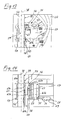
Figur 11 Figur 13- eine perspektivische Darstellung der Einzelheit X aus
Figur 11 Figur 14- einen Längsschnitt durch die Tragsäule und das Klemmstück gemäß der Linien XIV-XIV in
Figur 13 Figur 15- eine vergrößerte Darstellung der Einzelheit
X von Figur 11 , wobei das Klemmstück in einer Lösestellung gezeigt ist, Figur 16- eine Längsschnitt durch die Tragsäule und das Klemmstück gemäß der Linie XVI-XVI in
Figur 15 Figur 17- eine perspektivische Darstellung einer alternativen Ausführungsform des Klemmstücks, wobei sich das Klemmstück in der Klemmstellung befindet,
Figur 18- eine Draufsicht auf das
Klemmstück von Figur 17 mit einem Querschnitt durch die Tragsäule, Figur 19- eine perspektivische Darstellung des
Klemmstücks von Figur 17 , wobei sich das Klemmstück in der Lösestellung befindet, Figur 20- eine Draufsicht auf das
Klemmstück von Figur 19 , mit einem Querschnitt durch die Tragsäule, Figur 21- eine Draufsicht auf das zweite Ausführungsbeispiel des Beschlags gemäß
Figur 3 im im Eckschrank eingebauten Zustand, wobei sich das Tablar in seiner Innenstellung befindet, Figur 22- eine Draufsicht auf den
Beschlag gemäß Figur 21 , wobei sich das Tablar in einer Zwischenstellung befindet und Figur 23- eine Draufsicht auf den
Beschlag gemäß Figur 21 , wobei sich das Tablar in seiner Außenstellung befindet.
- FIG. 1
- a perspective view of a first embodiment of the fitting according to the invention attached to a support column, wherein it is provided via attachment interfaces for attachment to a tray,
- FIG. 2
- a perspective view of the fitting of
FIG. 1 from below with the mounting interfaces on the tray underside of the tray, - FIG. 3
- a perspective view of a second embodiment of the fitting according to the invention attached to a support column, wherein it is provided via attachment interfaces for attachment to a tray,
- FIG. 4
- a perspective view of the fitting of
FIG. 1 from below with the mounting interfaces on the tray underside, - FIG. 5
- a schematic bottom view of a tray with a further embodiment of an interface pattern at attachment interfaces,
- FIG. 6
- a bottom view of a tray according to
FIG. 5 with one oppositeFIG. 5 different interface patterns at attachment interfaces, - FIG. 7
- a schematic representation of the tray of
FIG. 5 with one opposite theFIGS. 5 and 6 different interface patterns at attachment interfaces, - FIG. 8
- a bottom view of the second embodiment of the fitting of the invention
FIG. 3 in the installed in the corner cabinet state, wherein the tray is in its inner position, - FIG. 9
- a bottom view of the fitting with tray of
FIG. 8 with the tray in an intermediate position, - FIG. 10
- a bottom view of the fitting with tray according to
FIG. 8 with the tray in the outward position, - FIG. 11
- a perspective sectional view of the fitting according to the invention with tray attached to the support column at a first height position,
- FIG. 12
- a perspective sectional view of the fitting with tray of
FIG. 11 attached to the support column at a second height position, - FIG. 13
- a perspective view of the detail X from
FIG. 11 . - FIG. 14
- a longitudinal section through the support column and the clamping piece according to the lines XIV-XIV in
FIG. 13 . - FIG. 15
- an enlarged view of the detail X of
FIG. 11 wherein the clamping piece is shown in a release position, - FIG. 16
- a longitudinal section through the support column and the clamping piece according to the line XVI-XVI in
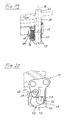
FIG. 15 . - FIG. 17
- a perspective view of an alternative embodiment of the clamping piece, wherein the clamping piece is in the clamping position,
- FIG. 18
- a plan view of the clamping piece of
FIG. 17 with a cross section through the support column, - FIG. 19
- a perspective view of the clamping piece of
FIG. 17 , wherein the clamping piece is in the release position, - FIG. 20
- a plan view of the clamping piece of
FIG. 19 , with a cross section through the support column, - FIG. 21
- a plan view of the second embodiment of the fitting according to
FIG. 3 in the built-in corner cabinet, with the tray is in its inner position, - FIG. 22
- a plan view of the fitting according to
FIG. 21 , wherein the tray is in an intermediate position and - FIG. 23
- a plan view of the fitting according to
FIG. 21 , with the tray is in its outward position.
Die
Es ist ferner noch ein Schrankboden 20 vorgesehen. Vorderwand 18 und Eckschranktür 19 nehmen in etwa zu gleichen Teilen die Vorderseite 17 ein. Der rechteckige Schrankkorpus 13 begrenzt einen dementsprechend rechteckigen Innenraum 21, der in etwa hälftig über die Eckschranktür 19 zugänglich ist.It is also still a cabinet bottom 20 is provided.
Im Innenraum des Eckschranks 11 befindet sich wenigstens ein Tablar 22, das mittels des Beschlags 12 zwischen einer Innenstellung, in der das Tablar 22 vollständig im Innenraum 21 untergebracht ist, und einer Außenstellung, in der das Tablar 22 zumindest teilweise über eine Ebene 23 einer Türöffnung des Eckschranks 11 hinaussteht, in einer Schwenkebene beweglich gesteuert wird. Es ist hier beispielhaft ein einzelnes Tablar 22 dargestellt. Alternativ ist es möglich, dass im Eckschrank 11 zwei oder mehr übereinanderliegende Tablare 22 angeordnet sind. Ferner ist das Tablar 22 beispielshaft in einteiliger Ausführungsform dargestellt. Es ist jedoch auch möglich, mehrteilige Tablare 22 einzusetzen.In the interior of the
Auch der Grundriss des Tablars 22 ist beispielhaft in Form einer Niere dargestellt. Das Tablar 22 besitzt an seiner der Vorderwand 18 zugewandten Innenseite eine Taillierung 24, um ein bequemes Herausschwenken aus dem Innenraum 21 bzw. Hineinschwenken in den Innenraum 21 zu ermöglichen, ohne dass das Tablar 22 an der Vorderwand 18 anstößt bzw. hängen bleibt.Also, the floor plan of the
Der Beschlag 12 besitzt wenigstens einen einerseits um eine im eingebauten Zustand des Tablars 22 ortsfeste Schwenkachse 25 schwenkbar gelagerten und andererseits an einer tablarfesten Lagerachse 26 schwenkbar am zugeordneten Tablar gelagerten Tragarm zur Tablarabstützung und eine Steuereinrichtung zur Steuerung der Tablarbewegung in der Schwenkebene zwischen der Innen- und der Außenstellung.The fitting 12 has at least one pivotally mounted on the one hand to a fixed in the installed state of the
Die Steuereinrichtung besitzt ferner zwei Steuerhebel, von denen einer zugleich den Tragarm bildet und in Gestalt eines kombinierten Steuer-/ Traghebels 27 ausgebildet ist, der gegenüber dem anderen Steuerhebel 28 rechtwinkelig zur Schwenkebene eine größere Biegesteifigkeit aufweist. Der Steuer-/Traghebel übt also eine Doppelfunktion aus, so steuert er als Steuerhebel die Tablarbewegung zwischen der Innen- und Außenstellung und stützt das Tablar 22 als Tragarm ab. Der Steuerhebel 28 ist ebenfalls einerseits um eine ortsfeste Schwenkachse 29 und andererseits um eine tablarfeste Lagerachse 30 bezüglich dieser drehbar und unverschieblich gelagert. Auch der Steuer-/ Traghebel 27 ist um seine tablarfeste Lagerachse 26 bezüglich dieser drehbar und unverschieblich gelagert. Die beiden ortsfesten Schwenkachsen 25, 29 des Steuer-/ Traghebels 27 und des Steuerhebels 28 sind benachbart zueinander angeordnet oder fallen zusammen, wobei bei den dargestellten Ausführungsbeispielen beispielhaft eine benachbarte Anordnung der ortsfesten Schwenkachsen 25, 29 gezeigt ist.The control device further has two control levers, one of which also forms the support arm and is designed in the form of a combined control /
Um eine ausreichend große Biegesteifigkeit des Steuer-/ Traghebels 27 zu erzielen, damit er seiner Funktion als Tragarm zur Tablarabstützung nachkommen kann, wird dieser von einem Metall-Vierkantrohr gebildet. Wie insbesondere in
Im Gegensatz zum Steuer-/ Traghebel 27 wird der Steuerhebel 28 von einer Flacheisenstange gebildet. Wie insbesondere in
Es sind also beide ortsfeste Schwenkachsen 25, 29 des Steuer-/ Traghebels 27 und des Steuerhebels 28 am Klemmstück 34 angeordnet, wobei gemäß den beschriebenen Ausführungsbeispielen die ortsfeste Schwenkachse 25 des Steuer-/ Traghebels 27 näher an einer Längsachse 38 einer nachfolgend näher beschriebenen Tragsäule 39 gelagert ist als die ortsfeste Schwenkachse 29 des Steuerhebels 28. Ferner ist die Hebellänge des Steuer-/ Traghebels 27 größer als die Hebellänge des Steuerhebels 28, so dass die tablarfeste Lagerachse 26 des Steuer-/Traghebels 27 einen Kreisbogen mit größerem Radius beschreibt als die tablarfeste Lagerachse 30 des Steuerhebels 28. Dadurch ergibt sich eine Relativbewegung von Steuer-/ Traghebel 27 und Steuerhebel 28 bei der Tablarbewegung zwischen der Innen- und der Außenstellung.So there are both stationary pivot axes 25, 29 of the control /
Wie bereits erwähnt sind beide tablarfesten Lagerachsen 26, 30 des Steuer-/ Traghebels 27 und des Steuerhebels 28 an einem Verbindungsglied 36 angeordnet, das also diese beiden tablarfesten Lagerachsen 26, 30 miteinander verbindet. Das Verbindungsglied 36 besitzt hierzu einen Achsträger 40, an dem in zuvor beschriebener Weise die beiden tablarfesten Lagerachsen 26, 30 gelagert sind.As already mentioned, both
Der Achsträger 40 ist jochartig ausgestaltet und besitzt einen plattenartigen ersten Achsschenkel 41a und einen parallel hierzu verlaufenden plattenartigen zweiten Achsschenkel 41b, die über zwei Abstandhalter 42 in Form von Materialstegen auf Abstand zueinander gehalten sind. Zwischen den beiden Achsschenkeln 41a, 41b befindet sich die am Steuer-/ Traghebel 27 endseitig angesetzte Lagerhülse 31. Im Gegensatz dazu ist der Steuerhebel 28 lediglich an einem der beiden Achsschenkel 41a, 41b mittels des die tablarfeste Lagerachse 30 bildenden Lagerstiftes gelagert.The
Neben dem Achsträger 40 weist das Verbindungsglied 36 auch noch einen langgestreckten Stützarm 43 auf, der ebenfalls als Vierkantrohr ausgestaltet ist. Stützarm 43 und Achsträger 40 sind starr miteinander verbunden, können beispielsweise aneinander angeschweißt sein. Dabei bilden die tablarfesten Lagerachsen 26, 30 am Achsträger 40 eine Verbindungslinie 44, die stumpfwinkelig zu einer Längsachse 45 des Stützarms 43 verläuft (
Am Stützarm 43 ist wenigstens eine Befestigungslasche 49 vorgesehen, über die der Stützarm 43 an der Tablarunterseite 46 befestigt werden kann. Zweckmäßigerweise befindet sich die Befestigungslasche 49 am Stützarm-Ende, das dem Achsträger 40 entgegengesetzt ist.On the
Der Eckschrank 11 besitzt ferner die bereits erwähnte Tragsäule 39 mit einer Längsachse 38. Die Tragsäule 39 ist über eine Lagerplatte 50 am Schrankboden 20 befestigt und steht frei im Schrankkorpus 13, ist also mit den Seitenwänden 15, 16 sowie mit Vorderwand 18 und Rückwand 14 nicht verbunden. Am dem Schrankboden 20 entgegengesetzten Ende der Tragsäule 39 ist eine weitere Lagerplatte 51 angesetzt, über die die Tragsäule 39 an einer Schrankabdeckung (nicht dargestellt) gelagert ist. Die Tragsäule 39 ist als Teleskopsäule ausgestaltet und besitzt hierzu ein Säulenunterteil 52 und ein linear verschieblich im Säulenunterteil 52 gelagertes Teleskopteil 53. Die Teleskopierbarkeit der Tragsäule 39 erlaubt deren Anpassung an unterschiedliche Eckschrankhöhen.The
Der Beschlag 12 ist mittels einer Befestigungsvorrichtung an der Tragsäule 39 befestigt. Zur Befestigungsvorrichtung gehört das bereits erwähnte Klemmstück 34 oder Lagerelement das Klemmmittel besitzt, die zwischen einer den Beschlag 12 an der Tragsäule 39 in gewünschter Höhenlage relativ zur Tragsäule 39 unverschieblich festklemmenden Klemmstellung 54 und einer eine stufenlose Höhenverstellung des Beschlags entlang der Tragsäule 39 ermöglichende Lösestellung 55 verstellbar sind.The fitting 12 is fixed by means of a fastening device to the
Das Klemmstück 34 ist Bestandteil des Beschlags 12. Es besitzt einen Grundkörper 56 und zwei relativ zueinander bewegliche Klemmbacken 57, 58, mit denen sich die zugeordnete Tragsäule 39 zumindest teilweise umgreifen lässt. Am Grundkörper 56 befindet sich die U-förmige Lagerpartie 33, in der die Lagerhülse 31 des Steuer-/ Traghebels 27 aufgenommen ist, und mittels des die ortsfeste Schwenkachse 25 bildenden Lagerbolzens schwenkbar gelagert ist. Einer der Schenkel der Lagerpartie 33 ist plattenartig ausgestaltet und weist die Durchgangsöffnung 37 auf, an der mit Hilfe des die ortsfeste Schwenkachse 29 bildenden Lagerstifts der Steuerhebel 28 schwenkbar gelagert ist. Es ist möglich, dass dieser plattenartige Schenkel mehrerer solcher Durchgangsöffnungen aufweist, so dass die ortsfestes Schwenkachse 29 umgesetzt werden kann, wodurch sich der Schwenkradius des Steuerhebels 28 und dessen Stellung zum Steuer-/ Traghebel 27 verändern lässt.It has a
Wie insbesondere in den
Die
Die bewegliche zweite Klemmbacke 58 ist gemäß der ersten Ausführungsform mittels Führungsmitteln in Axialrichtung zur Längsachse 38 der Tragsäule 39 linear verschieblich gelagert, wobei gleichzeitig eine in Axialrichtung ausgerichtete Klemmfläche der Klemmbacke 58 in Radialrichtung nach innen auf die starre erste Klemmbacke zu verlagerbar ist. Gemäß erster Ausführungsform besitzt die bewegliche Klemmbacke 58 zwei Backenglieder 61a, 61b, die in Axialrichtung zur Längsachse 38 der Tragsäule 39 mittels Stellmitteln relativ zueinander beweglich am Grundkörper 56 des Klemmstücks 34 gelagert sind, wobei bei einer Aufeinanderzu-Bewegung eine Verlagerung der Klemmflächen an den Backengliedern 61a, 61b nach radial innen erfolgt. Um dieses zu erreichen, sind an den Backengliedern 61a, 61b am den Klemmflächen 60a, 60b entgegengesetzten Ende jeweils Führungsschrägen 62a, 62b ausgebildet, die Teil der Führungsmittel sind. Wie insbesondere in den
Um das Klemmstück 34 in der gewünschten Höhenlage an der Tragsäule 39 zu befestigen, werden die beiden Klemmbacken 57, 58 zunächst in die Lösestellung 55 gebracht, wobei die beiden Backenglieder 61a, 61b voneinander weg bewegt werden. Dies kann durch Herausschrauben der Stellschraube 34 durchgeführt werden. Dadurch entsteht eine Einführöffnung 59, deren Querschnitt größer ist als der Querschnitt der Tragsäule 39, so dass das Klemmstück 34 seitlich an die Tragsäule 39 angesetzt werden kann. Nach dem Ansetzen wird die Stellschraube 64 wieder eingedreht, wodurch die beiden Backenglieder 61a, 61b aufeinander zu bewegt werden. Da die Backenglieder mit ihren Führungsschrägen 62a, 62b jeweils auf der Abgleitfläche 63 abgleiten, werden die Klemmflächen 60a, 60b der Backenglieder 61a, 61b in Richtung zur Außenseite der Tragsäule 39 hin bewegt und zwar solange, bis sie mit einer ausreichenden Klemmkraft auf die Tragsäule 39 drücken, wodurch das Klemmstück 34 an der Tragsäule 39 festgeklemmt ist.In order to secure the
Die
Um das Klemmstück 34 gemäß zweiter Ausführungsform an der Tragsäule 39 zu befestigen, werden die beiden Klemmbacken 57, 58 zunächst durch Herausschrauben der Feststellschraube 69 in die Lösestellung 55 gebracht. Dabei entsteht eine in
Dadurch, dass auf Seiten der Tragsäule 39 keine Komponenten bzw. Bauteile für die Befestigung des Klemmstücks 34 notwendig sind, kann das Klemmstück 34 stufenlos höhenverstellbar an jeder beliebigen Stelle entlang der Tragsäule, prinzipiell auch am Teleskopteil 53 festgeklemmt werden.The fact that no components or components for the attachment of the clamping
Wie insbesondere in den
Dabei bilden mehrere Befestigungsschnittstellen 70 ein Schnittstellenmuster 72, das derart ausgestaltet ist, dass der Beschlag 12 in zwei unterschiedlichen Befestigungspositionen am Tablar 22 befestigbar ist, so dass es je nach vorgegebener Befestigungsposition im Uhrzeigersinn oder alternativ im Gegen-Uhrzeigersinn von der Innen- in die Außenstellung schwenkbar ist. Die Befestigungsschnittstellen 70 sind als Befestigungslöcher ausgestaltet, in denen Schnittstellenmittel in Form von Befestigungselementen, beispielsweise Schrauben, Nieten oder dergleichen, die zuvor durch entsprechende Durchgangslöcher im Beschlag 12 hindurchgeführt werden, fixierbar sind.In this case, a plurality of
Gemäß dem in den
Wie insbesondere
Bei der Befestigung des Beschlags 12 gemäß dem ersten Ausführungsbeispiel wird der Stützarm 43 mit seiner Befestigungslasche an der in Y-Richtung ausgerichteten Schnittstellengruppe 74b an der einen Tablarhälfte 48 angesetzt und mittels den Befestigungsschrauben befestigt. Der Achsträger 40 mit seinem Lagerbolzen bzw. Lagerstift wird an die in X-Richtung ausgerichteten Schnittstellengruppe 74c an der anderen Tablarhälfte angesetzt und dort befestigt. Diese Befestigung ergibt eine Tablarbewegung gemäß den
Mit dem Schnittstellenmuster 72 gemäß dem ersten Ausführungsbeispiel ist es jedoch in einfacher Weise möglich, den Beschlag 12 und somit das Tablar 22 gegensinnig, also im Gegen-Uhrzeigersinn aus dem Innenraum 21 herausschwenken zu lassen. Hierzu wäre dann die Eckschranktür 11 auf der linken Seite angeordnet. Der Beschlag 12 wird hierzu um 180° umgeklappt und die Befestigungslasche 49 am Stützarm 43 wird an der anderen entgegengesetzten Seiten des Stützarms 43 befestigt. Der Stützarm 43 mit seiner Befestigungslasche 49 ragt dann in die Tablarhälfte 48 hinein, in der in der anderen Befestigungsposition der Achsträger 40 platziert war, während der Achsträger 40 jetzt in die Tablarhälfte 48 hineinragt, in der vorher der Stützarm 43 mit seiner Befestigungslasche 49 positioniert war. Bei der Befestigung des Beschlags 12 wird die Befestigungslasche 49 mit Hilfe der Befestigungsschrauben dann wieder an der in Y-Richtung ausgerichteten Schnittstellengruppe 74d befestigt, während der Achsträger 40 mit den Lagerbolzen bzw. -stiften dann an der anderen Tablarhälfte 48 an der in X-Richtung ausgerichteten Schnittstellengruppe 74a befestigt wird.With the
Das Tablar 22 kann also je nach Bedarf entweder links oder rechts herum aus dem Innenraum 21 herausschwenken.The
Die
Die Schnittstellenmittel 71 umfassen eine Adapterplatte 75, die an der Oberseite des vierkantrohrartigen Stützarms 43 lösbar befestigt ist. Die Adapterplatte 75 besitzt Durchstecklöcher 76, beispielsweise korrespondierend zur Anzahl der Befestigungsschnittstellen 70 vier an der Zahl. Durch die Durchstecklöcher 76 werden Befestigungselemente, beispielsweise Befestigungsschrauben hindurch gesteckt und in den korrespondierenden Befestigungsschnittstellen 70 an der Tablarunterseite 46 fixiert. An der Adapterplatte 75 befinden sich zweckmäßigerweise in Längsrichtung zwischen zwei Durchstecklöchern 76 Zentrierelemente in Gestalt von nach oben über die Oberseite der Adapterplatte 75 hinausragenden Zentrierzungen 77, die in korrespondierende Zentrierlöcher 78 an der Tablarunterseite 46, die zweckmäßigerweise ebenfalls in X-Richtung zwischen zwei Befestigungsschnittstellen 70 angeordnet sind, eingeführt werden können. Mittels den korrespondierenden Zentrierzungen 77 und Zentrierlöchern 78 lässt die Adapterplatte lagegenau positionieren, wodurch die fluchtende Lage zwischen den Durchstecklöchern 76 an der Adapterplatte 75 und den Befestigungsschnittstellen 70 automatisch erreicht wird.The interface means 71 comprise an
Auch das zweite Ausführungsbeispiel eignet sich in einfacher Weise für ein gegensinniges Herausschwenken des Tablars 22 aus dem Innenraum 21. Hierzu wird der Beschlag 12 wiederum um 180° umgeklappt und die Adapterplatte 75 auf der entgegengesetzten Seite des Stützarms 43 befestigt. Im Gegensatz zum zuvor beschriebenen Ausführungsbeispiel werden nun wiederum alle Befestigungsschnittstellen 70 verwendet und die Adapterplatte 75 wird an der gleichen Stelle an der Tablarunterseite 46 angebracht wie zuvor. Auch hier lässt sich also das Tablar 22 je nach Bedarf links oder rechts herum herausschwenken, wobei die Eckschranktür dann entweder auf der linken oder rechten Seite angeordnet ist.Also, the second embodiment is suitable in a simple manner for an opposing pivoting out of the
Die
Schließlich zeigt
Der Beschlag 12 besitzt weiterhin eine Ein- und Auszugeinrichtung 79 zur Unterstützung der Ein- und Ausfahrbewegung des Tablars in die Innen- und Außenstellung. Die Ein- und Auszugeinrichtung 79 besitzt eine Federeinheit 80, die einerseits an einer ortsfesten Feder-Lagerstelle 81 und andererseits an einer bei der Tablarbewegung mitbewegten beweglichen Lagerstelle 82 derart gelagert ist, dass auf den Beschlag 12 ein die Einfahrbewegung unterstützendes Drehmoment in Richtung der Innenstellung und nach Überschreitung eines Totpunktes ein die Ausfahrbewegung unterstützendes Drehmoment in Richtung der Außenstellung ausgeübt wird. Wie insbesondere in den
Die ortsfeste Schwenkachse und die bewegliche Lagerstelle 82 der Feder am Steuerhebel 28 definieren eine Gerade bezüglich der die ortsfeste Feder-Lagerstelle 81 bei der Unterstützung der Einfahrbewegung auf der einen und bei der Unterstützung der Ausfahrbewegung auf der anderen Seite liegt.The fixed pivot axis and the
Gemäß
Es ist ferner eine Dämpfungseinrichtung 83 zur Dämpfung der Tablarbewegung beim Einfahren in die Innenstellung und/oder Ausfahren in die Außenstellung vorgesehen. Die Dämpfungseinrichtung 83 weist einen Stoßdämpfer 84 auf, der derart angeordnet ist, dass er sowohl bei der Annäherung an die Innenstellung als auch bei der Annäherung an die Außenstellung dämpft und in mindestens einer zwischen der Innen- und der Außenstellung liegenden Zwischenstellung wirkungslos ist. Der Stoßdämpfer 84 ist gemäß den
Am Steuerhebel 28 befinden sich zwei an unterschiedlichen Positionen angeordnete Anschlagflächen 87a, 87b, die mit dem Dämpfungskolben 86 derart zusammenwirken, dass bei Annäherung an die Innenstellung ein Dämpfungsanschlag von Stoßdämpfer 84 und der einen Anschlagfläche 87a und bei Annäherung an die Außenstellung ein Dämpfungsanschlag von Stoßdämpfer 84 und der anderen Anschlagfläche 87b vorliegt. Der ein und derselbe Stoßdämpfer 84 dämpft also sowohl bei der Annäherung an die Innenstellung als auch bei der Annäherung an die Außenstellung. Die beiden Endlagen des Tablar 22, also die Innen- und die Außenstellung, werden gedämpft.On the
Da die tablarfesten Lagerachsen 26, 30 des Steuer-/ Traghebels 27 und des Steuerhebels 28 Kreisbahnen mit unterschiedlichen Durchmessern durchlaufen kommt es zu einer Relativbewegung von Steuer-/ Traghebel 27 und Steuerhebel 28. Aufgrund dieser Tatsache sind die beiden an unterschiedlichen Positionen angeordneten Anschlagflächen 87a, 87b vorgesehen. Dabei ist eine der Anschlagflächen an einer Stirnseite eines am Steuerhebel 28 befestigten Anschlagglieds 88 angeordnet, wobei diese Anschlagfläche 87b bezüglich einer Längsachse durch den Steuerhebel weiter radial außen angeordnet ist als die andere Anschlagfläche 87a.Since the tablarfesten bearing axes 26, 30 of the control /
Der Beschlag 12 und das Tablar 22 befinden sich also zunächst in der in
Claims (17)
Applications Claiming Priority (1)
| Application Number | Priority Date | Filing Date | Title |
|---|---|---|---|
| DE202010002230U DE202010002230U1 (en) | 2010-02-05 | 2010-02-05 | Fitting for a corner cupboard and corner cupboard |
Publications (2)
| Publication Number | Publication Date |
|---|---|
| EP2353440A1 true EP2353440A1 (en) | 2011-08-10 |
| EP2353440B1 EP2353440B1 (en) | 2016-04-13 |
Family
ID=42146073
Family Applications (1)
| Application Number | Title | Priority Date | Filing Date |
|---|---|---|---|
| EP11000793.7A Active EP2353440B1 (en) | 2010-02-05 | 2011-02-02 | Fitting for a corner cupboard and corner cupboard |
Country Status (2)
| Country | Link |
|---|---|
| EP (1) | EP2353440B1 (en) |
| DE (1) | DE202010002230U1 (en) |
Cited By (1)
| Publication number | Priority date | Publication date | Assignee | Title |
|---|---|---|---|---|
| WO2019120465A1 (en) * | 2017-12-18 | 2019-06-27 | Easyfill Ab (Publ) | A shelf assembly |
Families Citing this family (4)
| Publication number | Priority date | Publication date | Assignee | Title |
|---|---|---|---|---|
| DE202014103097U1 (en) * | 2014-07-07 | 2015-10-08 | Hetal-Werke Franz Hettich Gmbh & Co. Kg | Attachment device for a support element on a support column |
| DE202015101212U1 (en) * | 2015-03-10 | 2016-06-14 | Hetal-Werke Franz Hettich Gmbh & Co. Kg | Attachment device for a support element on a support column of a piece of furniture and furniture |
| DE202016004737U1 (en) | 2016-08-02 | 2017-11-03 | Hetal-Werke Franz Hettich Gmbh & Co. Kg | Hardware for a corner cabinet |
| EP3375328B1 (en) | 2017-03-17 | 2019-10-09 | Vauth-Sagel Holding GmbH & Co. KG | Clamping device for fixing in different longitudinal positions on a stretched support |
Citations (3)
| Publication number | Priority date | Publication date | Assignee | Title |
|---|---|---|---|---|
| EP1597985A1 (en) * | 2004-05-18 | 2005-11-23 | Heinrich J. Kesseböhmer KG | Corner cupboard, in particular kitchen corner cupboard |
| DE202004011200U1 (en) | 2004-07-16 | 2005-12-01 | Heinrich J. Kesseböhmer KG | Corner cupboard, especially kitchen corner cupboard |
| EP1925238A1 (en) * | 2006-11-27 | 2008-05-28 | Hetal-Werke Franz Hettich GmbH & Co. KG | Fitting for a corner cupboard and corner cupboard |
-
2010
- 2010-02-05 DE DE202010002230U patent/DE202010002230U1/en not_active Expired - Lifetime
-
2011
- 2011-02-02 EP EP11000793.7A patent/EP2353440B1/en active Active
Patent Citations (3)
| Publication number | Priority date | Publication date | Assignee | Title |
|---|---|---|---|---|
| EP1597985A1 (en) * | 2004-05-18 | 2005-11-23 | Heinrich J. Kesseböhmer KG | Corner cupboard, in particular kitchen corner cupboard |
| DE202004011200U1 (en) | 2004-07-16 | 2005-12-01 | Heinrich J. Kesseböhmer KG | Corner cupboard, especially kitchen corner cupboard |
| EP1925238A1 (en) * | 2006-11-27 | 2008-05-28 | Hetal-Werke Franz Hettich GmbH & Co. KG | Fitting for a corner cupboard and corner cupboard |
Cited By (3)
| Publication number | Priority date | Publication date | Assignee | Title |
|---|---|---|---|---|
| WO2019120465A1 (en) * | 2017-12-18 | 2019-06-27 | Easyfill Ab (Publ) | A shelf assembly |
| RU2742792C1 (en) * | 2017-12-18 | 2021-02-10 | Изифилл Аб (Пабл) | Shelving assembly |
| US11083312B2 (en) | 2017-12-18 | 2021-08-10 | Easyfill Ab (Publ) | Shelf assembly |
Also Published As
| Publication number | Publication date |
|---|---|
| DE202010002230U1 (en) | 2010-05-06 |
| EP2353440B1 (en) | 2016-04-13 |
Similar Documents
| Publication | Publication Date | Title |
|---|---|---|
| EP2353436B1 (en) | Fitting for a corner cupboard and corner cupboard | |
| EP3612700B1 (en) | Furniture wall with a flap fitting and a furniture body and furniture with such a furniture wall | |
| EP2531070B1 (en) | Pull-out guide for a drawer | |
| EP2002944B1 (en) | Machine stands | |
| EP2538818B1 (en) | Pull-out guide for drawers | |
| EP2092850B1 (en) | Fitting for a corner cupboard | |
| WO2006042344A1 (en) | Damping arrangement | |
| EP2353440B1 (en) | Fitting for a corner cupboard and corner cupboard | |
| DE102008057336A1 (en) | clamp | |
| EP2353441B1 (en) | Fitting device for a corner cupboard | |
| EP3029248B1 (en) | Sliding device for a partition element and piece of furniture | |
| EP2636340B1 (en) | Guiding device for guiding a mobile furniture part relative to a furniture body | |
| EP3150786A1 (en) | Joint connection | |
| EP2505101B1 (en) | Guide device for guiding a furniture pull-out that moves relative to an item of furniture | |
| EP2526823A1 (en) | Cabinet with pull-out frame | |
| EP3181012A1 (en) | Guide device for guiding a movable part of a piece of furniture relative to the body of a piece of furniture | |
| EP1099900A1 (en) | Articulated support | |
| AT507690B1 (en) | FURNITURE FITTING FOR SOLDER CONNECTING TWO FURNITURE PARTS | |
| EP3625416B1 (en) | Spring pack for a lid holder | |
| DE202010002231U1 (en) | Fitting for a corner cupboard and corner cupboard | |
| DE102004063580A1 (en) | Furniture with movable furniture segment | |
| DE102015012641B3 (en) | articulation | |
| EP2367460B1 (en) | Front adjuster for drawers and drawer | |
| EP2191745B1 (en) | Fitting for a corner cupboard | |
| EP3681347B1 (en) | Panel carrier and drawer |
Legal Events
| Date | Code | Title | Description |
|---|---|---|---|
| PUAI | Public reference made under article 153(3) epc to a published international application that has entered the european phase |
Free format text: ORIGINAL CODE: 0009012 |
|
| AK | Designated contracting states |
Kind code of ref document: A1 Designated state(s): AL AT BE BG CH CY CZ DE DK EE ES FI FR GB GR HR HU IE IS IT LI LT LU LV MC MK MT NL NO PL PT RO RS SE SI SK SM TR |
|
| AX | Request for extension of the european patent |
Extension state: BA ME |
|
| 17P | Request for examination filed |
Effective date: 20120208 |
|
| 17Q | First examination report despatched |
Effective date: 20120912 |
|
| GRAP | Despatch of communication of intention to grant a patent |
Free format text: ORIGINAL CODE: EPIDOSNIGR1 |
|
| INTG | Intention to grant announced |
Effective date: 20151022 |
|
| GRAS | Grant fee paid |
Free format text: ORIGINAL CODE: EPIDOSNIGR3 |
|
| GRAA | (expected) grant |
Free format text: ORIGINAL CODE: 0009210 |
|
| AK | Designated contracting states |
Kind code of ref document: B1 Designated state(s): AL AT BE BG CH CY CZ DE DK EE ES FI FR GB GR HR HU IE IS IT LI LT LU LV MC MK MT NL NO PL PT RO RS SE SI SK SM TR |
|
| REG | Reference to a national code |
Ref country code: GB Ref legal event code: FG4D Free format text: NOT ENGLISH |
|
| REG | Reference to a national code |
Ref country code: AT Ref legal event code: REF Ref document number: 789117 Country of ref document: AT Kind code of ref document: T Effective date: 20160415 Ref country code: CH Ref legal event code: EP |
|
| REG | Reference to a national code |
Ref country code: IE Ref legal event code: FG4D Free format text: LANGUAGE OF EP DOCUMENT: GERMAN |
|
| REG | Reference to a national code |
Ref country code: DE Ref legal event code: R096 Ref document number: 502011009391 Country of ref document: DE |
|
| REG | Reference to a national code |
Ref country code: SE Ref legal event code: TRGR |
|
| REG | Reference to a national code |
Ref country code: LT Ref legal event code: MG4D |
|
| REG | Reference to a national code |
Ref country code: NL Ref legal event code: MP Effective date: 20160413 |
|
| PG25 | Lapsed in a contracting state [announced via postgrant information from national office to epo] |
Ref country code: PL Free format text: LAPSE BECAUSE OF FAILURE TO SUBMIT A TRANSLATION OF THE DESCRIPTION OR TO PAY THE FEE WITHIN THE PRESCRIBED TIME-LIMIT Effective date: 20160413 Ref country code: NL Free format text: LAPSE BECAUSE OF FAILURE TO SUBMIT A TRANSLATION OF THE DESCRIPTION OR TO PAY THE FEE WITHIN THE PRESCRIBED TIME-LIMIT Effective date: 20160413 Ref country code: FI Free format text: LAPSE BECAUSE OF FAILURE TO SUBMIT A TRANSLATION OF THE DESCRIPTION OR TO PAY THE FEE WITHIN THE PRESCRIBED TIME-LIMIT Effective date: 20160413 Ref country code: NO Free format text: LAPSE BECAUSE OF FAILURE TO SUBMIT A TRANSLATION OF THE DESCRIPTION OR TO PAY THE FEE WITHIN THE PRESCRIBED TIME-LIMIT Effective date: 20160713 Ref country code: LT Free format text: LAPSE BECAUSE OF FAILURE TO SUBMIT A TRANSLATION OF THE DESCRIPTION OR TO PAY THE FEE WITHIN THE PRESCRIBED TIME-LIMIT Effective date: 20160413 |
|
| PG25 | Lapsed in a contracting state [announced via postgrant information from national office to epo] |
Ref country code: RS Free format text: LAPSE BECAUSE OF FAILURE TO SUBMIT A TRANSLATION OF THE DESCRIPTION OR TO PAY THE FEE WITHIN THE PRESCRIBED TIME-LIMIT Effective date: 20160413 Ref country code: HR Free format text: LAPSE BECAUSE OF FAILURE TO SUBMIT A TRANSLATION OF THE DESCRIPTION OR TO PAY THE FEE WITHIN THE PRESCRIBED TIME-LIMIT Effective date: 20160413 Ref country code: GR Free format text: LAPSE BECAUSE OF FAILURE TO SUBMIT A TRANSLATION OF THE DESCRIPTION OR TO PAY THE FEE WITHIN THE PRESCRIBED TIME-LIMIT Effective date: 20160714 Ref country code: LV Free format text: LAPSE BECAUSE OF FAILURE TO SUBMIT A TRANSLATION OF THE DESCRIPTION OR TO PAY THE FEE WITHIN THE PRESCRIBED TIME-LIMIT Effective date: 20160413 Ref country code: ES Free format text: LAPSE BECAUSE OF FAILURE TO SUBMIT A TRANSLATION OF THE DESCRIPTION OR TO PAY THE FEE WITHIN THE PRESCRIBED TIME-LIMIT Effective date: 20160413 Ref country code: PT Free format text: LAPSE BECAUSE OF FAILURE TO SUBMIT A TRANSLATION OF THE DESCRIPTION OR TO PAY THE FEE WITHIN THE PRESCRIBED TIME-LIMIT Effective date: 20160816 |
|
| REG | Reference to a national code |
Ref country code: DE Ref legal event code: R097 Ref document number: 502011009391 Country of ref document: DE |
|
| PG25 | Lapsed in a contracting state [announced via postgrant information from national office to epo] |
Ref country code: DK Free format text: LAPSE BECAUSE OF FAILURE TO SUBMIT A TRANSLATION OF THE DESCRIPTION OR TO PAY THE FEE WITHIN THE PRESCRIBED TIME-LIMIT Effective date: 20160413 Ref country code: EE Free format text: LAPSE BECAUSE OF FAILURE TO SUBMIT A TRANSLATION OF THE DESCRIPTION OR TO PAY THE FEE WITHIN THE PRESCRIBED TIME-LIMIT Effective date: 20160413 Ref country code: CZ Free format text: LAPSE BECAUSE OF FAILURE TO SUBMIT A TRANSLATION OF THE DESCRIPTION OR TO PAY THE FEE WITHIN THE PRESCRIBED TIME-LIMIT Effective date: 20160413 Ref country code: SK Free format text: LAPSE BECAUSE OF FAILURE TO SUBMIT A TRANSLATION OF THE DESCRIPTION OR TO PAY THE FEE WITHIN THE PRESCRIBED TIME-LIMIT Effective date: 20160413 Ref country code: RO Free format text: LAPSE BECAUSE OF FAILURE TO SUBMIT A TRANSLATION OF THE DESCRIPTION OR TO PAY THE FEE WITHIN THE PRESCRIBED TIME-LIMIT Effective date: 20160413 |
|
| PLBE | No opposition filed within time limit |
Free format text: ORIGINAL CODE: 0009261 |
|
| STAA | Information on the status of an ep patent application or granted ep patent |
Free format text: STATUS: NO OPPOSITION FILED WITHIN TIME LIMIT |
|
| REG | Reference to a national code |
Ref country code: FR Ref legal event code: PLFP Year of fee payment: 7 |
|
| PG25 | Lapsed in a contracting state [announced via postgrant information from national office to epo] |
Ref country code: SM Free format text: LAPSE BECAUSE OF FAILURE TO SUBMIT A TRANSLATION OF THE DESCRIPTION OR TO PAY THE FEE WITHIN THE PRESCRIBED TIME-LIMIT Effective date: 20160413 |
|
| 26N | No opposition filed |
Effective date: 20170116 |
|
| PG25 | Lapsed in a contracting state [announced via postgrant information from national office to epo] |
Ref country code: BE Free format text: LAPSE BECAUSE OF NON-PAYMENT OF DUE FEES Effective date: 20170228 Ref country code: SI Free format text: LAPSE BECAUSE OF FAILURE TO SUBMIT A TRANSLATION OF THE DESCRIPTION OR TO PAY THE FEE WITHIN THE PRESCRIBED TIME-LIMIT Effective date: 20160413 |
|
| PG25 | Lapsed in a contracting state [announced via postgrant information from national office to epo] |
Ref country code: MC Free format text: LAPSE BECAUSE OF FAILURE TO SUBMIT A TRANSLATION OF THE DESCRIPTION OR TO PAY THE FEE WITHIN THE PRESCRIBED TIME-LIMIT Effective date: 20160413 |
|
| REG | Reference to a national code |
Ref country code: CH Ref legal event code: PL |
|
| PG25 | Lapsed in a contracting state [announced via postgrant information from national office to epo] |
Ref country code: LI Free format text: LAPSE BECAUSE OF NON-PAYMENT OF DUE FEES Effective date: 20170228 Ref country code: CH Free format text: LAPSE BECAUSE OF NON-PAYMENT OF DUE FEES Effective date: 20170228 |
|
| REG | Reference to a national code |
Ref country code: IE Ref legal event code: MM4A |
|
| PG25 | Lapsed in a contracting state [announced via postgrant information from national office to epo] |
Ref country code: LU Free format text: LAPSE BECAUSE OF NON-PAYMENT OF DUE FEES Effective date: 20170202 |
|
| REG | Reference to a national code |
Ref country code: FR Ref legal event code: PLFP Year of fee payment: 8 Ref country code: BE Ref legal event code: MM Effective date: 20170228 |
|
| PG25 | Lapsed in a contracting state [announced via postgrant information from national office to epo] |
Ref country code: IE Free format text: LAPSE BECAUSE OF NON-PAYMENT OF DUE FEES Effective date: 20170202 |
|
| REG | Reference to a national code |
Ref country code: AT Ref legal event code: MM01 Ref document number: 789117 Country of ref document: AT Kind code of ref document: T Effective date: 20170202 |
|
| PG25 | Lapsed in a contracting state [announced via postgrant information from national office to epo] |
Ref country code: AT Free format text: LAPSE BECAUSE OF NON-PAYMENT OF DUE FEES Effective date: 20170202 |
|
| REG | Reference to a national code |
Ref country code: DE Ref legal event code: R082 Ref document number: 502011009391 Country of ref document: DE Representative=s name: REHBERG HUEPPE + PARTNER PATENTANWAELTE PARTG , DE |
|
| PG25 | Lapsed in a contracting state [announced via postgrant information from national office to epo] |
Ref country code: MT Free format text: LAPSE BECAUSE OF FAILURE TO SUBMIT A TRANSLATION OF THE DESCRIPTION OR TO PAY THE FEE WITHIN THE PRESCRIBED TIME-LIMIT Effective date: 20160413 |
|
| PG25 | Lapsed in a contracting state [announced via postgrant information from national office to epo] |
Ref country code: AL Free format text: LAPSE BECAUSE OF FAILURE TO SUBMIT A TRANSLATION OF THE DESCRIPTION OR TO PAY THE FEE WITHIN THE PRESCRIBED TIME-LIMIT Effective date: 20160413 |
|
| PG25 | Lapsed in a contracting state [announced via postgrant information from national office to epo] |
Ref country code: HU Free format text: LAPSE BECAUSE OF FAILURE TO SUBMIT A TRANSLATION OF THE DESCRIPTION OR TO PAY THE FEE WITHIN THE PRESCRIBED TIME-LIMIT; INVALID AB INITIO Effective date: 20110202 |
|
| PG25 | Lapsed in a contracting state [announced via postgrant information from national office to epo] |
Ref country code: BG Free format text: LAPSE BECAUSE OF FAILURE TO SUBMIT A TRANSLATION OF THE DESCRIPTION OR TO PAY THE FEE WITHIN THE PRESCRIBED TIME-LIMIT Effective date: 20160413 |
|
| PG25 | Lapsed in a contracting state [announced via postgrant information from national office to epo] |
Ref country code: CY Free format text: LAPSE BECAUSE OF NON-PAYMENT OF DUE FEES Effective date: 20160413 |
|
| PG25 | Lapsed in a contracting state [announced via postgrant information from national office to epo] |
Ref country code: MK Free format text: LAPSE BECAUSE OF FAILURE TO SUBMIT A TRANSLATION OF THE DESCRIPTION OR TO PAY THE FEE WITHIN THE PRESCRIBED TIME-LIMIT Effective date: 20160413 |
|
| PG25 | Lapsed in a contracting state [announced via postgrant information from national office to epo] |
Ref country code: TR Free format text: LAPSE BECAUSE OF FAILURE TO SUBMIT A TRANSLATION OF THE DESCRIPTION OR TO PAY THE FEE WITHIN THE PRESCRIBED TIME-LIMIT Effective date: 20160413 |
|
| PG25 | Lapsed in a contracting state [announced via postgrant information from national office to epo] |
Ref country code: IS Free format text: LAPSE BECAUSE OF FAILURE TO SUBMIT A TRANSLATION OF THE DESCRIPTION OR TO PAY THE FEE WITHIN THE PRESCRIBED TIME-LIMIT Effective date: 20160813 |
|
| PGFP | Annual fee paid to national office [announced via postgrant information from national office to epo] |
Ref country code: FR Payment date: 20230217 Year of fee payment: 13 |
|
| PGFP | Annual fee paid to national office [announced via postgrant information from national office to epo] |
Ref country code: SE Payment date: 20230220 Year of fee payment: 13 Ref country code: IT Payment date: 20230228 Year of fee payment: 13 |
|
| P01 | Opt-out of the competence of the unified patent court (upc) registered |
Effective date: 20230528 |
|
| PGFP | Annual fee paid to national office [announced via postgrant information from national office to epo] |
Ref country code: DE Payment date: 20240228 Year of fee payment: 14 Ref country code: GB Payment date: 20240222 Year of fee payment: 14 |