EP2351812A2 - Apparatus and process for thermal decomposition of any kind of organic material - Google Patents
Apparatus and process for thermal decomposition of any kind of organic material Download PDFInfo
- Publication number
- EP2351812A2 EP2351812A2 EP20090764693 EP09764693A EP2351812A2 EP 2351812 A2 EP2351812 A2 EP 2351812A2 EP 20090764693 EP20090764693 EP 20090764693 EP 09764693 A EP09764693 A EP 09764693A EP 2351812 A2 EP2351812 A2 EP 2351812A2
- Authority
- EP
- European Patent Office
- Prior art keywords
- heating
- tube
- gases
- tri
- tubes
- Prior art date
- Legal status (The legal status is an assumption and is not a legal conclusion. Google has not performed a legal analysis and makes no representation as to the accuracy of the status listed.)
- Withdrawn
Links
Images


Classifications
-
- C—CHEMISTRY; METALLURGY
- C10—PETROLEUM, GAS OR COKE INDUSTRIES; TECHNICAL GASES CONTAINING CARBON MONOXIDE; FUELS; LUBRICANTS; PEAT
- C10B—DESTRUCTIVE DISTILLATION OF CARBONACEOUS MATERIALS FOR PRODUCTION OF GAS, COKE, TAR, OR SIMILAR MATERIALS
- C10B47/00—Destructive distillation of solid carbonaceous materials with indirect heating, e.g. by external combustion
- C10B47/02—Destructive distillation of solid carbonaceous materials with indirect heating, e.g. by external combustion with stationary charge
- C10B47/16—Destructive distillation of solid carbonaceous materials with indirect heating, e.g. by external combustion with stationary charge with indirect heating means both inside and outside the retorts
-
- C—CHEMISTRY; METALLURGY
- C09—DYES; PAINTS; POLISHES; NATURAL RESINS; ADHESIVES; COMPOSITIONS NOT OTHERWISE PROVIDED FOR; APPLICATIONS OF MATERIALS NOT OTHERWISE PROVIDED FOR
- C09C—TREATMENT OF INORGANIC MATERIALS, OTHER THAN FIBROUS FILLERS, TO ENHANCE THEIR PIGMENTING OR FILLING PROPERTIES ; PREPARATION OF CARBON BLACK ; PREPARATION OF INORGANIC MATERIALS WHICH ARE NO SINGLE CHEMICAL COMPOUNDS AND WHICH ARE MAINLY USED AS PIGMENTS OR FILLERS
- C09C1/00—Treatment of specific inorganic materials other than fibrous fillers; Preparation of carbon black
- C09C1/44—Carbon
- C09C1/48—Carbon black
- C09C1/482—Preparation from used rubber products, e.g. tyres
-
- C—CHEMISTRY; METALLURGY
- C10—PETROLEUM, GAS OR COKE INDUSTRIES; TECHNICAL GASES CONTAINING CARBON MONOXIDE; FUELS; LUBRICANTS; PEAT
- C10B—DESTRUCTIVE DISTILLATION OF CARBONACEOUS MATERIALS FOR PRODUCTION OF GAS, COKE, TAR, OR SIMILAR MATERIALS
- C10B53/00—Destructive distillation, specially adapted for particular solid raw materials or solid raw materials in special form
- C10B53/07—Destructive distillation, specially adapted for particular solid raw materials or solid raw materials in special form of solid raw materials consisting of synthetic polymeric materials, e.g. tyres
-
- F—MECHANICAL ENGINEERING; LIGHTING; HEATING; WEAPONS; BLASTING
- F23—COMBUSTION APPARATUS; COMBUSTION PROCESSES
- F23G—CREMATION FURNACES; CONSUMING WASTE PRODUCTS BY COMBUSTION
- F23G5/00—Incineration of waste; Incinerator constructions; Details, accessories or control therefor
- F23G5/02—Incineration of waste; Incinerator constructions; Details, accessories or control therefor with pretreatment
- F23G5/027—Incineration of waste; Incinerator constructions; Details, accessories or control therefor with pretreatment pyrolising or gasifying stage
-
- C—CHEMISTRY; METALLURGY
- C01—INORGANIC CHEMISTRY
- C01P—INDEXING SCHEME RELATING TO STRUCTURAL AND PHYSICAL ASPECTS OF SOLID INORGANIC COMPOUNDS
- C01P2006/00—Physical properties of inorganic compounds
- C01P2006/80—Compositional purity
-
- Y—GENERAL TAGGING OF NEW TECHNOLOGICAL DEVELOPMENTS; GENERAL TAGGING OF CROSS-SECTIONAL TECHNOLOGIES SPANNING OVER SEVERAL SECTIONS OF THE IPC; TECHNICAL SUBJECTS COVERED BY FORMER USPC CROSS-REFERENCE ART COLLECTIONS [XRACs] AND DIGESTS
- Y02—TECHNOLOGIES OR APPLICATIONS FOR MITIGATION OR ADAPTATION AGAINST CLIMATE CHANGE
- Y02P—CLIMATE CHANGE MITIGATION TECHNOLOGIES IN THE PRODUCTION OR PROCESSING OF GOODS
- Y02P20/00—Technologies relating to chemical industry
- Y02P20/141—Feedstock
- Y02P20/143—Feedstock the feedstock being recycled material, e.g. plastics
-
- Y—GENERAL TAGGING OF NEW TECHNOLOGICAL DEVELOPMENTS; GENERAL TAGGING OF CROSS-SECTIONAL TECHNOLOGIES SPANNING OVER SEVERAL SECTIONS OF THE IPC; TECHNICAL SUBJECTS COVERED BY FORMER USPC CROSS-REFERENCE ART COLLECTIONS [XRACs] AND DIGESTS
- Y02—TECHNOLOGIES OR APPLICATIONS FOR MITIGATION OR ADAPTATION AGAINST CLIMATE CHANGE
- Y02P—CLIMATE CHANGE MITIGATION TECHNOLOGIES IN THE PRODUCTION OR PROCESSING OF GOODS
- Y02P20/00—Technologies relating to chemical industry
- Y02P20/141—Feedstock
- Y02P20/145—Feedstock the feedstock being materials of biological origin
Definitions
- the present invention refers to an apparatus for thermal decomposition (dissociation) of any kind of organic material (biomasses, sludges, organic lees, cakes, brans, dry vinasse, composts, animal excrements, unusable tires, polymers in general, peat, etc.) to obtain commercial products such as oils (with fatty fractions, diesel, aromatics, limonene, tars, etc.) and coals (of the vegetable, lignite, bituminous, carbon black - NFR type, etc).
- the apparatus of this invention also enables the destruction of products and soils contaminated with oils, organochlorinated hydrocarbons and dioxins.
- Japanese patent JP 56115386 dating from 1981 describes apparatus for carbonizing old tires to generate heat. This is carried out by burning the gas generated to obtain coal without worrying about the recovery of the carbon black contained in the raw material. In other words, this apparatus does not allow the use of the reaction products which are the coals, recovered carbon black obtained when the raw material is tires, and oil.
- the tire is heated by direct contact of the combustion gas with the material to be processed, by way of the holes 5.
- the apparatus described in this Japanese patent is a simple gasifier with three concentric vessels.
- the present patent application describes an apparatus which allows the use of the reaction products, which are the coals (recovered carbon black obtained when the raw material is tires) and the oil.
- the constructive concepts of the Japanese patent JP 56115386 and of the present patent application are entirely different.
- Heating the tires (or any other raw material) in the present invention is performed indirectly by tri-tube technology (three concentric tubes).
- the raw material is placed in the space between the intermediary tube of the tri-tube and outer tube of the tri-tube and the heating gas passes through the area between the intermediary tube of the tri-tube and the inner tube of the tri-tube and also through the outer region of the tri-tube.
- the present invention is a hermetic apparatus which reproduces the geological formation conditions of coal, petroil and gases in the subsoil (as per Ernest Bayer), its fractionings, streamlined loading, unloading, low consumption of energy, investment cost, operational and processing of any kind of organic material including whole tires.
- British patent GB 362.522 dating from 1931 describes a machine that is operated on a batch regime for "carbonization at average temperature" in the range of 590°-C to 700°-C. Above 500oC the processes are pyrolytic (gasifications) and below 500oC are low temperature conversions (cracking + synthesis). It is noted that the range of usual operation of the present invention is between 380oC and 420oC. It is noted that below 380oC the reaction is very slow and not economically viable and above 420oC there begins the thermal decomposition of most of the oil generated by the process. Still regarding the British patent, it is important to note that once the reaction is over, there is a major difficulty in unloading the coke produced, because it adheres to the reactor walls. The following two measures are designed to overcome this problem:
- the present invention solves the problem of coal unloading in a simple and different manner: once the reaction is over, the reactor closing lid, which is mounted on a cart on rails, travels whereby releasing the reactor, the entire equipment is titled around its horizontal axis (which passes through the center of gravity of the apparatus) describing an angle of about 180 degrees.
- Japanese patent JP 10279950 dating from 1998 describes equipment for carbonizing old tires, waste vinyls, wood shavings, etc.
- the equipment has a vertical construction and is comprised of an outer oven and an inner over concentric to the former.
- the inner oven has an upper protrusion in relation to the outer oven.
- the constructive concepts of the Japanese patent JP 10279950 and of the present invention are entirely different.
- the problem of feeding the raw material and unloading of products in the Japanese patent is solved by bins introduced via the upper flange, which is installed on the protruding part of the inner tube. In the present invention there is no bin and the unloading is by tilting.
- the bin of patent JP 10279950 is divided into three parts: lower B1, intermediary B2 and upper B3. The lower part is closed to prevent the escape of coal and the upper and intermediary parts have holes which allow the product to be unloaded.
- the problem of unloading the product is solved by the equipment's tilting system.
- the reactor closing lid which is mounted on a cart on rails travels whereby releasing the reactor, the whole equipment is tilted around its horizontal axis (which passes through the center of gravity of the apparatus) describing an angle of about 180 degrees.
- a major problem of the equipment of the Japanese patent is having a single tube which if applied to industrial quantities implies large diameters.
- the carbonized material in the outer wall of the inner tube acts as thermal insulation for the material situated in the central part, requiring several hours and even days to finish the process, the apparatus thus being of little use for any industrial application.
- the apparatus of the present invention solved the issue of processing time by way of the tri-tubes with internal and external heating of the raw material situated in the annular part, which results in small material width and processing times of around 3 hours, thus allowing industrial capacity to be achieved.
- the present invention also comprises the possibility that gases used in the reaction may be at different temperatures in an alternative embodiment of the invention.
- British patent GB 330.980 dating from 1929 describes equipment for carbonizing coal mineral, peat, wood, etc.
- the constructive concepts of the British patent GB 330.980 and of the present patent are entirely different, starting with the operating principle which is continuous in the first and by batch in the second.
- British patent GB 330,980 describes an apparatus comprised of various vertical stationary containers (retorts) mounted according to a carrousel-type toroidal symmetry. Around this retorts carrousel is a bell with an annular profile forming a tunnel which covers the retorts carrousel.
- This tunnel is mounted on rollers and rails, has periodic circular movement and is insulated by a sand bath. The tunnel has loading, heating and cooling regions.
- Each retort also has an upper port for loading and a lower port for unloading the coal into a bin and each set of three retorts has a stationary piping for the outflow of vapors (subproducts). Through this collector piping, there are withdrawn the vapors generated in the process which are conveyed to a distillation plant.
- vapors subproducts
- North American patent 5.095.040 dating from 1992 is a process patent. It describes the use of conventional equipment (tire shredders, shaking screens, electro-magnets, storage hoppers, rotary ovens, burners, temperature controllers, condensation tower with content, oil tanks and chimney) for the thermal processing of old tires, in an environment free of atmospheric air, but non-hermetic.
- the process sequence is as follows: a) tire shredding; b) sorting the fine pieces sized between 1.27 cm (1 ⁇ 2") to 1.9 cm (3 ⁇ 4") and discarding of coarse material including metal; c) silo tampon of raw material (small pieces); d) carbonization in rotary oven in the absence of atmospheric air; and) recovery of the solid product (porous coal); f) condensation of vapors generating oil and g) burning or chimney disposal of the non-condensable gases.
- processing biomass containing lipids, proteins and lignocellulosics produces coal and processing tires produces recovered carbon black (NFR).
- the chemical composition and the applications of the oil is also not cited, but rather their physical properties 41.8 MJ/kg (18,000 BTU/pound), specific gravity of 0.90, pour point of -7 oC and boiling point of 112oC (oil # 4).
- the non-condensable gases are conveyed to the chimney or are burnt in one or more burners.
- the tube presents raising wings and material drag and slanting in the range of 5 to 10 degrees, the feeder mouth being higher than the unloading mouth for outflow of the material in process and to hinder the entry of air into the over.
- the rotation is slow in the order of 3 rpm.
- the residence time of the material processed in the rotary oven is 7 to 8 minutes resulting in an estimated production of 2 to 3 t/h due to the low rate of filling the rotary ovens.
- the rotary oven is surrounded by a thermally insulated box where there are installed burners directed towards the lower part of the rotary tube.
- Temperature sensors are installed in the body of the tube to keep the temperature at the desired conditions which are: entry of the rubber: 480oC to 540oC, region central: 480oC and coal outflow: 425oC to 440oC.
- the smoke 34 leaves the reactor in the temperature range of between 160oC and 190oC and the condensation tower operates in the range of 60oC to 70oC.
- the estimated heating rate is 125oC/min falling in the inert rapid pyrolysis rate.
- North American patent 5.095.040 highlights that the use of a rotary oven with smooth walls, instead of systems of belts or propeller conveyors, avoids locking problems due to the adhesive characteristic of the material processed. North American patent 5.095.040 , therefore, has no characteristic resembling the present invention.
- the present invention describes new equipment and consequently a new process, which is not pyrolysis, because it is below 500oC and in an inert atmosphere (totally free of O 2 ), from whence the name low temperature conversion.
- the process used by the present invention there occurs cracking and synthesis simultaneously permitted by the residence time of 60 to 90 minutes and, accordingly, results in maximization (increase in quantity) and improved quality of the oils.
- the main equipment needed to develop the process described in the North American patent is a conventional rotary oven which is a machine having constructive characteristics entirely different from the heat exchange-type reactor with tri-tube beams defined in the present invention. Operations of the rotary oven are continuous and the reactor of the present invention is by batch.
- oil containing fractions of limonene and aromatics
- recovered carbon black containing original carbon black original and the ashes (compounds of zinc and sulphur, silicon, aluminum, iron, titanium, potassium, etc.) used in manufacturing rubbers) and non-condensable gases.
- organochlorides and dioxins and furans PCB, HCB, PCDD and PCDF
- the present invention refers to a CBT reactor which allows the simultaneous realization of the functions of a vessel and a heat exchanger and its chemical reactions and thermal exchanges.
- the reactor is constituted of square arrangements (or any other geometrical shape) of three concentric tubes in the tri-tube configurations up to a number of tri-tubes that is technically and economically viable.
- the defining factor for the quantity of tri-tubes is a technical and economic analysis of the project to be implemented.
- the tube trios of the present invention are disposed vertically with loading of raw material by hoppers, through the upper part and unloading of the solid products by tilting the reactor.
- the hot heating gas enters simultaneously by the outer wall of the tri-tube by the region between the inner tube and intermediary tube of the tri-tube and leaves by the smallest inner tube called bayonet.
- the tubes are preferably made of stainless steel 310, and other steels can be used that are resistant to average temperatures (380°C to 450oC).
- the total flow regime of the CBT Reactor (including all the processing steps - from loading to unloading) is by batch and lasts approximately 6 to 8 hours, depending on the raw material.
- the batch steps are: feeding, heating, processing with extraction and condensation of the oil, cooling, tilting and processing of the coal.
- the reactor In each batch, the reactor is kept hermetic, free of oxygen, using N 2 or CO 2 as drag gas.
- the raw material is dried in an external dryer to an approximate minimum of 95% dried matter.
- the process phases are as follows: the solid phase of the reaction which occurs in the annular region, between the outer tube and the intermediary tube, has inorganic catalysts that are part of the raw material itself (SiO 2 , Al 2 O 3 , FeO 3 , TiO 2 , K 2 O, Zn, etc.).
- the vapors phase vapors of tars, fatty oil, diesel, aromatics, limonenes, monomers of hydrocarbons and water
- the non-condensable gases phase CO, CO 2 , H 2 , CH 4 , N 2 , etc.
- external catalysts can be mixed to the raw materials during drying in rotary ovens, fluid beds or turbodryers.
- the existing phases, outside the outer tube and inside the intermediary tube and inner tube, comprise combustion gases from the hot gas generator generated externally for heating the CBT Reactor.
- the movement conditions of the materials during the period of a reaction inside the CBT reactor are: 1) Raw material - Upper loading via hoppers in 240 seconds; 2) Solids (raw material being converted) - Fixed bed during the batch processing period of 6 to 8 hours; 3) Vapors and non-condensable gases - Extraction by the annular region of the tri-tube also during the batch period of 6 to 8 hours; 4) Heating Combustion Gas and cooling air - Continuous flow with residence period of 8 seconds; 5) Coal - Unloading by tilting in approximately 120 seconds.
- the vapors and non-condensable gases can have an upwards or downwards flow (extraction by purge of N 2 ) in the annular region, the latter being designed to widen the contact thereof with the catalysts present in the solid mass.
- the diameter of the raw material used in the reactor of the present invention goes from submillimetric particles (brans, cakes, lees, sludges, excrement), centimetric for bulks (shavings, shredded plastics) and briquettes (remainder of agricultural reforestry, sawmills and grasses) and metric particles for tires from cars, trucks and tractors that are treated whole, without the need for shredding.
- the sizes of the tri-tube may vary according to the specific needs. The greatest demand is for car tires. Materials with apparently low density are previously briquetted in cylindrical or toroidal forms having diameters similar to those of car tires.
- the heat transfer rate and mass of the CBT reactor constitutes significant ingeniousness of the present invention.
- the major fraction of products involved in the reaction is coal (40 to 60%), a thermal insulator that hampers the transfer of heat for conversion.
- the present invention solves this issue by way of tri-tubes with heating from the outside and inside of the annular region keeping the heat transmission width lower than approximately 175 mm permitting a reduction in the conversion period to approximately 3 hours, this being 4 to 10 times lower than conventional carbonization ovens.
- a good mass processing rate is achieved with apparently specific average volumes of the raw materials processed (Table 1).
- the temperature control is excellent due to the continuous heating with combustion gas of the hot gas generator and the metal conductivity of the tri-tube beam of the CBT reactor.
- the hot gas generator can use any kind of fuel (biomass, oil, gas natural or GLP). Thermal cycling (steps of heating, converting and cooling), allows the production of 3 to 4 batches per day.
- the present invention can be considered as an apparatus for thermal decomposition of any kind of organic material comprising an outer box with hermetic lid, a thermal insulation layer disposed throughout the inner surface of the outer box and lid, and also comprising at least a structure with three concentric tubes disposed internally, positioned substantially vertically and with a wall width suitable for heating by means of gases from the inside and outside of said structure.
- the structure with three concentric tubes comprises an inner tube, an intermediary tube and an outer tube and is heated on the outside and inside of the annular region of the tubes.
- the spacing between the inner wall of the outer tube and the outer wall of the intermediary tube is approximately 175 mm.
- the structure with three concentric tubes has substantially thin walls the width of which varies from 2 to 5 mm, preferably, 3 mm and a length substantially equal to that of the apparatus.
- the heat flow for heating transferred by conduction to the three concentric tubes occurs simultaneously from the inside of the intermediary tube to the center of the annular region of the three concentric tubes and from the outside of the outer tube to the center of the annular region of the three concentric tubes, the gases used for heating have no physical contact with the material to be decomposed. Heating by hot gases in a process regime allows the difference in temperature between the inflow and the outflow of the gases to be approximately 15°C.
- said apparatus is a batch operation reactor.
- the material used in the outer box is preferably carbon steel.
- the material used in the concentric tubes is preferably stainless steel 310, and other materials can be used that are resistant to average temperatures of between 380°C and 420°C.
- the material used inside the outer box and lid is preferably a refractory blanket for thermal insulation of the outer structure and viton or silicon seals in closing the apparatus lid.
- the apparatus of the present invention comprises air compressor devices and blowers to provide N2 or CO2 to purge vapors and non-condensable gases, as well as a heating gas feed and outflow assembly.
- the heating gas feed and outflow assembly comprises a hot gas inflow coupling, a hot gas inflow plenum, a lower mirror for homogenization of the flow of hot gas, an intermediary mirror, a heating gas capture duct, a heating gas outflow plenum and a heating gas outflow coupling.
- the apparatus of the present invention also preferably comprises two cooling circuits.
- the first cooling circuit comprises the same heating pipework and is implemented by insufflation by a ventilator and by the outflow of hot gas into the chimney.
- the internal cooling is by the circulation of inert gas (N 2 or CO 2 ) directly on the coal in the annular part of the tubes.
- the second cooling circuit comprises a purge channel, an outflow of vapors and non-condensable gases and the recirculation of neutral gases in a heat exchanger by Blower Roots.
- the present invention also comprises a process for the thermal decomposition of any kind of organic material using the apparatus as previously described and comprises the steps of feeding organic material into the apparatus; heating with gases on the inside and outside of an annular region located in the concentric tubes inside the apparatus; processing with region located in the concentric tubes inside the apparatus; processing with extraction and condensation of oil; and cooling with gases; and tilting of the apparatus.
- the process also comprises a conversion step that maintains a difference in temperature between the inflow and outflow of the hot heating gases in a process regime of approximately 15°C.
- Heating for conversion of the reaction material is carried out for approximately 3 hours, preferably, 165 minutes.
- the heating is carried out outside the outer tube and inside the intermediary tube and inner tube. Cooling for unloading the reaction material is carried out for approximately 2 hours.
- N 2 is pumped into the apparatus to expel the oxygen. Heating the reaction is carried out by means of feeding hot gas simultaneously to all tubes.
- the process also comprises the steps of extraction and condensation of vapors and non-condensable gases generated in conversion.
- the CBT reactor generally uses four main materials in its manufacturing: a) Carbon steel in the outer structure of the reactor operating at ambient temperature, b) stainless steel 310 or other similar refractory steel indicated for the working temperature of between 380oC and 420oC, c) Refractory blanket, thermally insulating the outer structure of the reactor heat exchanger per se of the inner temperature and, d) viton or silicon seals in closing the reactor lid.
- the mechanical resistances of the materials existing on the market (bearings, etc.) allows the manufacturing of a CBT reactor with up to 64 tri-tubes (table 2).
- the main external operations of the process of the reactor are: a) drying the raw materials in rotary dryers, fluid beds or turbodryers; b) feeding; c) generation of hot gas in furnaces using any kind of fuel; d) extraction and fractioned condensation or not of the vapors and non-condensable gases generated in conversion; and) thermal exchange carried out by means of cooling water tower and pump, heat exchangers of condensation of the vapors and the gas wash water; f) supply of N 2 or CO 2 g) unloading and processing of the coals.
- the water cooling towers are substituted by freon or cryogenic refrigeration.
- the feed hoppers are square or round boxes having bipartite butterfly valves for each tri-tube. After being loaded, the hoppers are hoisted by overhead crane, positioned on top of the reactor and unloaded. For larger reactors, the hoppers are divided in half or in quarters so as to respect the highway regulatory dimensions and also enable the loading of raw materials at their generation points.
- Processing the coals can be simplified or complete. Processing is simplified when it is destined for fuels in bulk. It is complete in the case of recovered carbon black (NFR) obtained from the conversion of tires which first have a sorting step of the steel mesh followed by grinding and classification into particles smaller than 20 ⁇ m, 7 ⁇ m or 1 ⁇ m.
- NFR recovered carbon black
- the apparatus of the present invention allows the total destruction of the dioxins by installing the molten salt bed (850oC) at the outflow of the non-condensable gases for cases in which the raw material contains these polluents.
- the following basic steps occur: drying the external raw material; simultaneous feeding of all the tri-tubes by hoppers having bipartite butterfly valves for each tri-tube; heating of the reactor by way of the hot gas generator using any kind of fuel; cooling of the reactor using the same system of air suction of heating (the furnace being turned on) for admitting the cold air; and extraction and fractioned condensation or not of the vapors and non-condensable gases generated in the conversion; cooling of the heat exchanger used in the condensation of vapors and of the heat exchanger of the gas washer by way of the freon or cryogenic cooling tower for monomers generated by the polymers.
- the present invention uses compressed air compressors in its instruments and blowers for the supply of N 2 or CO 2 so as to purge the vapors and non-condensable gases.
- the processing can be simplified (dispatch or packaging) or complete (grinding and classification of the coals).
- recovered carbon black (NFR) is produced from processing used tires. Sealing can be totally by the lid of the reactor or individual in each tri-tube. Unloading is carried out by tilting.
- the raw materials are classified as follows: I a : Clean Biomass: Wood, Reforestry Residues and Bushes (vegetable-type coal and tar); I b: Clean Biomass with Potassium contamination: Agricultural Residues, Grasses, Bagasse and Cane Straw (Vegetable Coal and Tar); II: Cakes, Brans, Grain Residues, Dry Fats, Meat Meal, Bone Meal, Blood meal, etc.
- Table 1 Apparent Specific Average Masses of Various Raw materials Class Raw material Kg/m 3 la Clean Biomass: Wood, Reforesty Residues and Bushes 150 Ib Clean Biomass with potassium contamination: Agricultural Residues, Grasses, Bagasse and Cane Straw 150 II Cakes, Brans, Grain Residues, Dry Fats, Meat Meal, Bone Meal, Blood meal, etc.
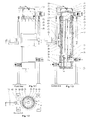
- FIGS 1.1 to 1.4 and 2.1 to 2.3 illustrate the CBT reactors of the present invention with 1 tri-tube and 32 tri-tubes, respectively, which use the same concept differentiating amongst themselves in size only.
- Parts 1 to 5 comprise the structure support 1, the outer box 2, the tilting axis 3, the motor-reducer 4 and thermal insulation of the reactor 5.
- Parts 7 to 10 form the tri-tube assembly which comprises an inner tube 7, the intermediary tube 8, the outer tube 9 and the purge tube 10.
- the tri-tube constitutes the main item of the present invention and is part 8 of the concepts, namely: fixed bed reactor, heat exchanger, inert gas drag bed, size of viabilization by virtue of low thermal conduction caused by the coal formed during the process (thermal insulation), cooling with neutral gas (N 2 or CO 2 ) directly to overcome the thermal insulation of the coal formed, coincidence of size of prior item with the size of passenger car tires, useful occupation of approximately 1/3 of the total volume of the reactor and low impedance in the fluidodynamics of the heating gas and cooling outside the tri-tube.
- Parts 11 to 17, comprise the gas inflow coupling 11, hot gas inflow plenum 12, lower mirror 13 (hot gas flow homogenizer), intermediary mirror 14, heating gas capture duct 15, heating gas outflow plenum 16 and heating gas outflow coupling 17.
- Said parts show the feeder assembly and outflow of hot gas generated by the furnace.
- Part 18 shows the upper mirror which supports the load of the tri-tubes in operation (vertical position) and during the tilting assisted by the parts 13 (lower mirror) 14 (intermediary mirror), 16 (hot gas inflow and outflow plenum) with reduced thermal loss for the outer structure due to the use of stainless steels and thermal insulation.
- Part 19 shows the lid of the reactor, which is closed by way of a hydraulic cylinder.
- Part 19 is sealed by way of soft and hard rubbers around it.
- Part 25 shows the outflow of vapors and gases installed in the lid 19, which is connected to the venturi 55 ( figure 3 ) by coupling 27 driven by hydraulic cylinders 28.
- Part 29 shows the lid movement cart with a locking system and rotational movement on rails.
- Part 37 is a possible substitution of 4 to 5 tri-tubes which can receive passenger car tires by a tri-tube that can receive truck tires ( figure 2.2 ). The ratio of passenger car tires to truck tires is 20/1 and it is suffice to install a single tri-tube in each reactor to process the truck tires.
- the distance between the outer tube 9 and the intermediary tube 8 of the tri-tube for truck tires strays from the efficient distance of heat transfer, this drawback being compensated by the increase in reaction time (two consecutive batches) by blocking its unloading after the first reaction. Blocking is carried out by a locking device that may or may not be mounted on the apparatus itself.
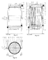
- Figure 2.1 shows a CBT reactor with 32 tri-tubes, which has a circular section and can also be constituted with a square section.
- the reactor will have 4 tri-tubes more than the prior version.
- the tri-tube of the present invention can have a section in any shape, provided that the effective distance for the heat transfer is maintained. This arrangement has a greater investment cost, but a lower operating cost due to greater production by batch. Industrial practice will show which of the arrangements is economically more advantageous.
- the CBT reactor with 1 tri-tube and the CBT reactor with 32 tri-tubes also comprise a global lid 19 for the tri-tubes with hermetic sealing rings made of cooled rubber 23, hydraulic cylinder 24 with rotary engagement to pressure the lid against the rings supported on the body of the reactor, thermal insulation 5 (for example, ceramic fiber) upper mirror 18 and support structure 1.
- This same global lid is applied to receive a square section.
- the main difference is that the structure is a profile I in the square section reactor and having a U-shaped profile in the circular section reactor.
- the CBT reactor can also operate with the option of an individual lid for each tri-tube.
- the parts are the same as the prior options, the only variation being their positioning in the reactor.
- the vapors and non-condensable gases outflow coupling of the global lid option comprises the following parts: vapors and non-condensable gases outflow 25, flange 26, expansion joint 27 and hydraulic cylinder 28.
- the disengagement of the parts 25 to 28 permits lid movement on the cart in order to release the tilting of the reactor; part 27 is the expansion joint and part 28 is a hydraulic cylinder which retracts the engagement; the coupling assembly is fixed on the venturi pipework 55 ( figure 3 ) of condensation of the vapors and cooling of the non-condensable gases.
- a typical layout of the CBT Reactor Installation is illustrated in figure 3 where there occurs the feeding and unloading of the coal.
- a tire feed hopper 40 has bipartite butterfly valves for each tri-tube; the hopper is placed in stand-by position.
- the feed hopper 41 of contaminated sludges, etc., is in stand-by position.
- An overhead crane 42 takes the hoppers from the carts and raises to the stand-by position and subsequent to the top of the reactor for feed operation; the overhead crane is also used for mounting and maintaining the equipment.
- the unloading hopper 43 receives the coal from the tilting of the reactor, such that they follow on to conveyor belt 44 and to the de-agglomerator roll 45, falling onto the conveyor belt 46.
- the steel is sorted by an electromagnet 47, then on to the conveyor belt 48 and to the baler 49.
- the coal follows down the snail 50 which transfers it to the bin elevator 51 which unloads the coal into the container 52 when it is used for energy purposes (fuel).
- the bin elevator 51 unloads the coal (NFR) into the hammer mill 53 and then to the classifier 54, having a baghouse which releases the classified end product to the Big-Bag bagger or into paper bags.
- the outflow of vapors and non-condensable gases 25 leads to the venturi 55 condensing in the tank 56 from where they are pumped by the pump 57 to the condensation tower 58 by the heat exchanger 59. After condensation, the oil passes through the water/oil centrifuge 60 and then to the tank 61 having a storage pump 62. The non-condensable gases are suctioned by the ventilator 63 which transfers them to the demister 64 (condensed sorter) and are conveyed to the furnace 66. In polymer processing, the non-condensable gases (monomers) are condensed by cooling or cryogeny.
- the non-condensable gases pass through a high temperature burner and molten salt bed.
- the non-condensable gases after passing through the hydraulic seal 65 are burned in the high temperature furnace 66 with an auxiliary fuel flame (GLP, GN, Acethylene, etc.) such that these combustion gases pass through the molten salt bed 68 where the final destruction of the organochlorides and dioxins occurs.
- GLP auxiliary fuel flame
- the non-condensable gases are immediately burned in the biomass furnace 67.
- the combustion gases from both furnaces 66, 67 join the hot gas piping of the reactor suctioned by the hot gas ventilator 69.
- the temperature control is by way of the cold air damper (valve) in the hot air pipework.
- the outer circuit comprises the same heating pipework, which is carried out by insufflation by the ventilator 70 and by the hot gas outflow into the chimney 71.
- inert gas N 2 or CO 2
- the purge channel 10 and the vapors and non-condensable gases outflow 25 are used, but the neutral gases in the heat exchanger 72 are recirculated by Blower Roots 73.
- the sludges, cakes, excrements, etc. need to be dried with a maximum of 5% humidity to avoid oxidation of the oils. This drying is carried out in the dryer assembly by using any kind of dryer (rotary drum, fluid bed or turbodryer), using the reactor's hot heating gases exhaustion.
- peripheral equipment items not-illustrated also act, comprising the following units: water cooling tower, or freon or cryogenic cooler, water pumps, compressor, compressed air tank, tank and nitrogen or CO 2 blower.
- Figure 4 illustrates a heating and cooling curve of the CBT reactor and the accumulated conversion rate (raw material fraction that turns into coal, oil and non-condensable gases) of the matter contained in the reactor. Adding the loading and unloading period, the total processing time is approximately 6 to 8 hours permitting 4 to 3 batches per day.
- the apparatus of the present invention carries out the thermochemical almost isothermal conversion of any kind of organic material in various types of oils, coals and non-condensable gases according to the type of raw material used.
- the neo-isothermal reactors are situated in a narrow viability range dictated by the temperature difference ⁇ T between the inflow and outflow temperature of the heating means.
- AT decreases (tending towards zero) there is an annulment of the heat transfer capacity of the heating means to the raw material which is being processed.
- AT increases (tending towards zero) there is an annulment of the heat transfer capacity of the heating means to the raw material which is being processed.
- AT increases (tending towards zero) there is an annulment of the heat transfer capacity of the heating means to the raw material which is being processed.
- Increasing the heat transfer capacity with the objective of widening the processing capacity so to achieve economic viability requires an increase in AT, that is, an increase in the inflow temperature and/or decrease in the outflow temperature of the heating means.
- the first (increase in inflow temperature) is limited by the maximum decomposition temperature of the oils (450oC) and the second (decrease in outflow temperature) is limited by the minimum thermochemical conversion temperature of the organic materials (380oC).
- the invention has achieved a satisfactory conversion period of 3 hours dictated by the fact that the coals formed during the process are insulating materials, hampering the transfer of heat with the processing time.
- the same Period for heating the loaded reactor is also used for cooling the load to below 100oC before opening it in order to avoid spontaneous combustion of the coals.
- the heat flow transferred by conduction to the tri-tube occurs simultaneously by two means, namely: a) from the inside of the intermediary tube to the center of the annular region of the tri-tube b) from the outside of the outer tube to the center of the annular region of the tri-tube.
- Figure 6 presents the variation of the heat flow transferred by conduction and the heating rate in relation to the annular width of the tri-tube maintaining the other parameters constant. The following points are emphasized:
- the set of experiment data from the materials and the figures for thermal conductivity and specific heat near the coke coal results in an annual width of 175 mm. This width, besides allowing the treatment of unusable whole tires from passenger cars, assures the viability of an economic productivity for treating various materials (sludges, slurries, cakes, brans, wood, etc.).
- the thermal conductivity of the stainless steel is not a determining factor and the conductivity of the coal determines the heat conduction and consequently all the dimensions of the tri-tube and the conversion process of the present invention.
- the heat rate of stainless steel represents merely 18.3% of the total heating rate, that is, the raw material and products (coal) are the determining factors thereof.
- the heat flow of the inner tube represents 40% of the total flow and of the outer tube 60%.
- Another detail of the invention is the batch operation with loading by the upper lid and unloading by tilting by rotation around its axis which passes through the center of gravity.
- the lid is sealed by cooled sliding O-shaped rings (viton or silicon) giving the reactor a hermetic characteristic (free of oxygen) to prevent oxidation of the oil and coal formed.
- the invention maximizes the yield of the products represented by about 40% to 60% of coal, 10% to 30% of oil, 10% to 15% of water and 10% to 20% of and non-condensable gases in relation to the initial raw material. Opening the lid is by a small pneumatic lifting and side sliding by a motorized cart.
- Another detail of the invention is its capacity to process various types of raw materials generating different products, classed as follows: I a: Clean biomass: Wood, Reforestry Residues and Bushes generating vegetable-type coal and tar; I b: Clean biomass with Potassium contamination: Agricultural residues, Grasses, Bagasse and Cane Straw, also generating vegetable-type coal and tar; II: Cakes, brans, grain residues; Dry Fats, Meat Meal, Bone Meal, Blood meal, etc.
- Loading the apparatus is by hoppers having bipartite butterfly valves positioned above each tri-tube.
- the hoppers are previously loaded near the CBT or at the origin of generation of the raw materials and transported to the CBT in trucks and hoisted by overhead cranes to the floor at the reactor feed level.
- the hoppers are in stand-by position and after the reactor has unloaded the prior reaction, it returns to the loading position. Afterwards, the hoppers are positioned on the apparatus, and the bipartite butterfly valves are opened, quickly completing the loading (approximately 4 minutes).
- the hoppers can be single in the case of small apparatus (1 and 16 tubes), double in the case of average-sized apparatus (25, 36 and 49 tubes) and quadruple in the case of giant apparatus (64 tubes or more).
- the division of the hoppers allows them to have widths within the highway regulatory standards (max. 3.20m) allowing 'just-in-time' operations between supply and processing of biomass eliminating the need for large deposits of biomass and residues.
- the modulations of the reactors, subdivision of the hoppers having widths within the highway regulatory standards, load capacity supported by the structural materials determine the size of the apparatus of the present invention.
- the reactor of the present invention also enables fast unloading (approximately 2 minutes) of the solid products by way of tilting around the axis passing through the center of gravity of the apparatus. Unloading is carried out on a vibrating hopper which transports the solid products for the steps of finishing according to market demands (rolls or disintegrating mills, shakers, magnetic separators, hammer or disk mills having classifiers and packaging).
- Patent key An apparatus for Low Temperature Conversion
Abstract
The present invention refers to a Low Temperature Conversion apparatus composed of tri-tubes which simultaneously carries out the functions of vessel and heat exchanger. This apparatus is capable of thermally decomposing any kind of organic material to obtain coal, oil, water and non-condensable gases, and also decontaminating soils and residues contaminated with organochlorides and dioxins.
The apparatus is used for thermal decomposition of any kind of organic material and comprises: an outer box (2) with a hermetic lid (19); a thermal insulation layer (5) disposed throughout the inner surface of the outer box (2) and lid, said apparatus also comprising at least a structure with three concentric tubes disposed internally, positioned substantially vertically and with a wall width suitable for heating by means of gases from an inner side and outer side of said structure. The invention also refers to a process for thermal decomposition of any kind of organic material using the apparatus of the present invention and comprises the steps of feeding the organic material into the apparatus; heating with gases on the inside and outside of an annular region located in the concentric tubes inside the apparatus; processing with extraction and condensation of oil; cooling with gases; and tilting of the apparatus.
Description
- The present invention refers to an apparatus for thermal decomposition (dissociation) of any kind of organic material (biomasses, sludges, organic lees, cakes, brans, dry vinasse, composts, animal excrements, unusable tires, polymers in general, peat, etc.) to obtain commercial products such as oils (with fatty fractions, diesel, aromatics, limonene, tars, etc.) and coals (of the vegetable, lignite, bituminous, carbon black - NFR type, etc). The apparatus of this invention also enables the destruction of products and soils contaminated with oils, organochlorinated hydrocarbons and dioxins.
- Japanese patent
JP 56115386 JP56115386 holes 5. In point of fact, the apparatus described in this Japanese patent is a simple gasifier with three concentric vessels. - The present patent application describes an apparatus which allows the use of the reaction products, which are the coals (recovered carbon black obtained when the raw material is tires) and the oil. The constructive concepts of the Japanese patent
JP 56115386 - British patent
GB 362.522 - a) the volume of the coking chamber is increased by movement of the
hollow walls 2 which are articulated at one of its ends (figure 1 ). The product is disposed between pairs of boards and the heating is carried out in the space between the pairs of boards; - b) the machine has a device to push the coke which is added when the hollow walls are moved and at the same time the articulated doors in the lower part of the coking chamber are opened to allow coke unloading.
- The present invention solves the problem of coal unloading in a simple and different manner: once the reaction is over, the reactor closing lid, which is mounted on a cart on rails, travels whereby releasing the reactor, the entire equipment is titled around its horizontal axis (which passes through the center of gravity of the apparatus) describing an angle of about 180 degrees. The feed mouth of the tri-tube, which in the feeding and reaction steps faces upwards, on unloading faces downwards and becomes an unloading mouth. So the main differences between this patent and the present invention are:
- 1) patent
GB 362.522 - 2) patent
GB 362.522 - 3) patent
GB 362.522 - 4) the machine of patent
GB 362.522 - Japanese patent
JP 10279950 JP 10279950 JP 10279950 - In the present invention, the problem of unloading the product is solved by the equipment's tilting system. Once the reaction is over, the reactor closing lid which is mounted on a cart on rails travels whereby releasing the reactor, the whole equipment is tilted around its horizontal axis (which passes through the center of gravity of the apparatus) describing an angle of about 180 degrees. The feed mouth of the tri-tube, which in the feeding and reaction steps faces upwards, on unloading faces downwards and becomes an unloading mouth. A major problem of the equipment of the Japanese patent is having a single tube which if applied to industrial quantities implies large diameters. The carbonized material in the outer wall of the inner tube acts as thermal insulation for the material situated in the central part, requiring several hours and even days to finish the process, the apparatus thus being of little use for any industrial application. The apparatus of the present invention, besides various additional characteristics, solved the issue of processing time by way of the tri-tubes with internal and external heating of the raw material situated in the annular part, which results in small material width and processing times of around 3 hours, thus allowing industrial capacity to be achieved. It should be noted that the present invention also comprises the possibility that gases used in the reaction may be at different temperatures in an alternative embodiment of the invention.
- British patent
GB 330.980 GB 330.980 GB 330,980 - North American patent
5.095.040 dating from 1992 is a process patent. It describes the use of conventional equipment (tire shredders, shaking screens, electro-magnets, storage hoppers, rotary ovens, burners, temperature controllers, condensation tower with content, oil tanks and chimney) for the thermal processing of old tires, in an environment free of atmospheric air, but non-hermetic. The process sequence is as follows: a) tire shredding; b) sorting the fine pieces sized between 1.27 cm (½") to 1.9 cm (¾") and discarding of coarse material including metal; c) silo tampon of raw material (small pieces); d) carbonization in rotary oven in the absence of atmospheric air; and) recovery of the solid product (porous coal); f) condensation of vapors generating oil and g) burning or chimney disposal of the non-condensable gases. In the North American patent there is no mention of the characteristics and applications of the solid product (porous coal). In the present invention, processing biomass containing lipids, proteins and lignocellulosics produces coal and processing tires produces recovered carbon black (NFR). The chemical composition and the applications of the oil is also not cited, but rather their physical properties 41.8 MJ/kg (18,000 BTU/pound), specific gravity of 0.90, pour point of -7 ºC and boiling point of 112ºC (oil # 4). The non-condensable gases are conveyed to the chimney or are burnt in one or more burners. The main process step is the carbonization of rubber which is carried out in a rotary oven comprised of a stainless steel tube having the following dimensions: diameter = 609mm, length = 6.300mm and width of the stainless steel sheeting of 11.1 mm. The tube presents raising wings and material drag and slanting in the range of 5 to 10 degrees, the feeder mouth being higher than the unloading mouth for outflow of the material in process and to hinder the entry of air into the over. The rotation is slow in the order of 3 rpm. The residence time of the material processed in the rotary oven is 7 to 8 minutes resulting in an estimated production of 2 to 3 t/h due to the low rate of filling the rotary ovens. The rotary oven is surrounded by a thermally insulated box where there are installed burners directed towards the lower part of the rotary tube. Temperature sensors are installed in the body of the tube to keep the temperature at the desired conditions which are: entry of the rubber: 480ºC to 540ºC, region central: 480ºC and coal outflow: 425ºC to 440ºC. Thesmoke 34 leaves the reactor in the temperature range of between 160ºC and 190ºC and the condensation tower operates in the range of 60ºC to 70ºC. The estimated heating rate is 125ºC/min falling in the inert rapid pyrolysis rate. North American patent5.095.040 highlights that the use of a rotary oven with smooth walls, instead of systems of belts or propeller conveyors, avoids locking problems due to the adhesive characteristic of the material processed. North American patent5.095.040 , therefore, has no characteristic resembling the present invention. The present invention describes new equipment and consequently a new process, which is not pyrolysis, because it is below 500ºC and in an inert atmosphere (totally free of O2), from whence the name low temperature conversion. In the process used by the present invention there occurs cracking and synthesis simultaneously permitted by the residence time of 60 to 90 minutes and, accordingly, results in maximization (increase in quantity) and improved quality of the oils. The main equipment needed to develop the process described in the North American patent is a conventional rotary oven which is a machine having constructive characteristics entirely different from the heat exchange-type reactor with tri-tube beams defined in the present invention. Operations of the rotary oven are continuous and the reactor of the present invention is by batch. - It is an objective of the present invention to provide an apparatus with a geometry of multiple tube trios having fine walls called tri-tubes which simultaneously execute the functions of chemical reactor and heat exchanger.
- It is an objective of the present invention to keep the atmosphere in the annular region of the tri-tube free of oxygen to avoid oxidation of the raw materials and products during the chemical reaction.
- It is another objective of the apparatus of the present invention to have thermally-insulated outer walls to decrease the consumption of thermal heating energy for a chemical reaction.
- It is an objective of the present invention to load the raw materials and to unload the solid products quickly.
- It is another objective of the apparatus of the present invention to convert the raw materials containing lipids and proteins (jointly or separately) into oil, coal and non-condensable gases.
- It is another objective of the apparatus of the present invention to convert the lignocellulosic raw materials into oils (tar), coal, water and non-condensable gases.
- It is another objective of the apparatus of the present invention to convert tires and rubber in general into oil (containing fractions of limonene and aromatics), recovered carbon black (containing original carbon black original and the ashes (compounds of zinc and sulphur, silicon, aluminum, iron, titanium, potassium, etc.) used in manufacturing rubbers) and non-condensable gases.
- It is another objective of the apparatus of the present invention to convert plastics and polymers in general in their monomers (ethene, propene, styrene, etc), coals, ashes (compounds of zinc and sulphur, silicon, aluminum, iron, titanium, potassium, etc.) and non-condensable gases by cooling at freon or cryogenic temperatures.
- It is another objective of the apparatus of the present invention to treat contaminated soils or other materials with organochlorides and dioxins and furans (PCB, HCB, PCDD and PCDF) in order to obtain a resulting decontaminated material.
- It is another objective of the apparatus of the present invention to obtain purer separated ducts by fraction condensation or an even purer result than usual in order to allow uses of the resulting products differing from those listed in the energy field.
- The present invention refers to a CBT reactor which allows the simultaneous realization of the functions of a vessel and a heat exchanger and its chemical reactions and thermal exchanges. The reactor is constituted of square arrangements (or any other geometrical shape) of three concentric tubes in the tri-tube configurations up to a number of tri-tubes that is technically and economically viable. In other words, the defining factor for the quantity of tri-tubes is a technical and economic analysis of the project to be implemented.
- The tube trios of the present invention, called tri-tubes, are disposed vertically with loading of raw material by hoppers, through the upper part and unloading of the solid products by tilting the reactor. In the tri-tube arrangement, the hot heating gas enters simultaneously by the outer wall of the tri-tube by the region between the inner tube and intermediary tube of the tri-tube and leaves by the smallest inner tube called bayonet. This arrangement allows the temperature difference ΔT between inflow and outflow of the hot heating gases in a process regime to be just ΔT = 415 - 400 = 15ºC conferring the characteristic of isothermal reactor. The tubes are preferably made of stainless steel 310, and other steels can be used that are resistant to average temperatures (380°C to 450ºC).
- The total flow regime of the CBT Reactor (including all the processing steps - from loading to unloading) is by batch and lasts approximately 6 to 8 hours, depending on the raw material. The batch steps are: feeding, heating, processing with extraction and condensation of the oil, cooling, tilting and processing of the coal. In each batch, the reactor is kept hermetic, free of oxygen, using N2 or CO2 as drag gas. The raw material is dried in an external dryer to an approximate minimum of 95% dried matter.
- The process phases are as follows: the solid phase of the reaction which occurs in the annular region, between the outer tube and the intermediary tube, has inorganic catalysts that are part of the raw material itself (SiO2, Al2O3, FeO3, TiO2, K2O, Zn, etc.). The vapors phase (vapors of tars, fatty oil, diesel, aromatics, limonenes, monomers of hydrocarbons and water) and the non-condensable gases phase (CO, CO2, H2, CH4, N2, etc.) which are produced during conversion. It must be noted that external catalysts can be mixed to the raw materials during drying in rotary ovens, fluid beds or turbodryers. The existing phases, outside the outer tube and inside the intermediary tube and inner tube, comprise combustion gases from the hot gas generator generated externally for heating the CBT Reactor.
- The movement conditions of the materials during the period of a reaction inside the CBT reactor are: 1) Raw material - Upper loading via hoppers in 240 seconds; 2) Solids (raw material being converted) - Fixed bed during the batch processing period of 6 to 8 hours; 3) Vapors and non-condensable gases - Extraction by the annular region of the tri-tube also during the batch period of 6 to 8 hours; 4) Heating Combustion Gas and cooling air - Continuous flow with residence period of 8 seconds; 5) Coal - Unloading by tilting in approximately 120 seconds. The vapors and non-condensable gases can have an upwards or downwards flow (extraction by purge of N2) in the annular region, the latter being designed to widen the contact thereof with the catalysts present in the solid mass.
- The diameter of the raw material used in the reactor of the present invention goes from submillimetric particles (brans, cakes, lees, sludges, excrement), centimetric for bulks (shavings, shredded plastics) and briquettes (remainder of agricultural reforestry, sawmills and grasses) and metric particles for tires from cars, trucks and tractors that are treated whole, without the need for shredding. For truck tires, 4 or 5 tubes of ∅ = 650mm could be substituted for a single tube of approximately ∅ = 1.350 mm whose larger size demands a greater processing period. It should be noted that the sizes of the tri-tube may vary according to the specific needs. The greatest demand is for car tires. Materials with apparently low density are previously briquetted in cylindrical or toroidal forms having diameters similar to those of car tires.
- The heat transfer rate and mass of the CBT reactor constitutes significant ingeniousness of the present invention. The major fraction of products involved in the reaction is coal (40 to 60%), a thermal insulator that hampers the transfer of heat for conversion. The present invention solves this issue by way of tri-tubes with heating from the outside and inside of the annular region keeping the heat transmission width lower than approximately 175 mm permitting a reduction in the conversion period to approximately 3 hours, this being 4 to 10 times lower than conventional carbonization ovens. A good mass processing rate is achieved with apparently specific average volumes of the raw materials processed (Table 1). There is a fortunate coincidence between the optimal annular width for heat transmission (175 mm) and the width of tires of passenger vehicles integral, dispensing the need for costly shredding operations.
- The temperature control is excellent due to the continuous heating with combustion gas of the hot gas generator and the metal conductivity of the tri-tube beam of the CBT reactor. The hot gas generator can use any kind of fuel (biomass, oil, gas natural or GLP). Thermal cycling (steps of heating, converting and cooling), allows the production of 3 to 4 batches per day.
- The present invention can be considered as an apparatus for thermal decomposition of any kind of organic material comprising an outer box with hermetic lid, a thermal insulation layer disposed throughout the inner surface of the outer box and lid, and also comprising at least a structure with three concentric tubes disposed internally, positioned substantially vertically and with a wall width suitable for heating by means of gases from the inside and outside of said structure.
- The structure with three concentric tubes comprises an inner tube, an intermediary tube and an outer tube and is heated on the outside and inside of the annular region of the tubes. The spacing between the inner wall of the outer tube and the outer wall of the intermediary tube is approximately 175 mm. The structure with three concentric tubes has substantially thin walls the width of which varies from 2 to 5 mm, preferably, 3 mm and a length substantially equal to that of the apparatus.
- The heat flow for heating transferred by conduction to the three concentric tubes occurs simultaneously from the inside of the intermediary tube to the center of the annular region of the three concentric tubes and from the outside of the outer tube to the center of the annular region of the three concentric tubes, the gases used for heating have no physical contact with the material to be decomposed. Heating by hot gases in a process regime allows the difference in temperature between the inflow and the outflow of the gases to be approximately 15°C.
- Note that said apparatus is a batch operation reactor.
- The material used in the outer box is preferably carbon steel. The material used in the concentric tubes is preferably stainless steel 310, and other materials can be used that are resistant to average temperatures of between 380°C and 420°C. The material used inside the outer box and lid is preferably a refractory blanket for thermal insulation of the outer structure and viton or silicon seals in closing the apparatus lid.
- The apparatus of the present invention comprises air compressor devices and blowers to provide N2 or CO2 to purge vapors and non-condensable gases, as well as a heating gas feed and outflow assembly. The heating gas feed and outflow assembly comprises a hot gas inflow coupling, a hot gas inflow plenum, a lower mirror for homogenization of the flow of hot gas, an intermediary mirror, a heating gas capture duct, a heating gas outflow plenum and a heating gas outflow coupling.
- The apparatus of the present invention also preferably comprises two cooling circuits. The first cooling circuit comprises the same heating pipework and is implemented by insufflation by a ventilator and by the outflow of hot gas into the chimney. In a second cooling circuit the internal cooling is by the circulation of inert gas (N2 or CO2) directly on the coal in the annular part of the tubes. The second cooling circuit comprises a purge channel, an outflow of vapors and non-condensable gases and the recirculation of neutral gases in a heat exchanger by Blower Roots.
- The present invention also comprises a process for the thermal decomposition of any kind of organic material using the apparatus as previously described and comprises the steps of feeding organic material into the apparatus; heating with gases on the inside and outside of an annular region located in the concentric tubes inside the apparatus; processing with region located in the concentric tubes inside the apparatus; processing with extraction and condensation of oil; and cooling with gases; and tilting of the apparatus.
- The process also comprises a conversion step that maintains a difference in temperature between the inflow and outflow of the hot heating gases in a process regime of approximately 15°C. Heating for conversion of the reaction material is carried out for approximately 3 hours, preferably, 165 minutes. The heating is carried out outside the outer tube and inside the intermediary tube and inner tube. Cooling for unloading the reaction material is carried out for approximately 2 hours.
- In said process N2 is pumped into the apparatus to expel the oxygen. Heating the reaction is carried out by means of feeding hot gas simultaneously to all tubes.
- The process also comprises the steps of extraction and condensation of vapors and non-condensable gases generated in conversion.
- The CBT reactor generally uses four main materials in its manufacturing: a) Carbon steel in the outer structure of the reactor operating at ambient temperature, b) stainless steel 310 or other similar refractory steel indicated for the working temperature of between 380ºC and 420ºC, c) Refractory blanket, thermally insulating the outer structure of the reactor heat exchanger per se of the inner temperature and, d) viton or silicon seals in closing the reactor lid. The mechanical resistances of the materials existing on the market (bearings, etc.) allows the manufacturing of a CBT reactor with up to 64 tri-tubes (table 2).
- The main external operations of the process of the reactor are: a) drying the raw materials in rotary dryers, fluid beds or turbodryers; b) feeding; c) generation of hot gas in furnaces using any kind of fuel; d) extraction and fractioned condensation or not of the vapors and non-condensable gases generated in conversion; and) thermal exchange carried out by means of cooling water tower and pump, heat exchangers of condensation of the vapors and the gas wash water; f) supply of N2 or CO2 g) unloading and processing of the coals.
- To condense the monomers generated in the conversion of polymers (ethene, propene, etc.) the water cooling towers are substituted by freon or cryogenic refrigeration.
- The feed hoppers are square or round boxes having bipartite butterfly valves for each tri-tube. After being loaded, the hoppers are hoisted by overhead crane, positioned on top of the reactor and unloaded. For larger reactors, the hoppers are divided in half or in quarters so as to respect the highway regulatory dimensions and also enable the loading of raw materials at their generation points.
- Processing the coals can be simplified or complete. Processing is simplified when it is destined for fuels in bulk. It is complete in the case of recovered carbon black (NFR) obtained from the conversion of tires which first have a sorting step of the steel mesh followed by grinding and classification into particles smaller than 20 µm, 7 µm or 1 µm.
- Although the CBT destroys organochlorides and dioxins by the hermeticity of the process and rupture of the heterogeneous bonds (C-O, C-H, C-Cl, C-N, Cl-O etc.), the apparatus of the present invention allows the total destruction of the dioxins by installing the molten salt bed (850ºC) at the outflow of the non-condensable gases for cases in which the raw material contains these polluents.
- In the use of an embodiment of the reactor of the present invention the following basic steps occur: drying the external raw material; simultaneous feeding of all the tri-tubes by hoppers having bipartite butterfly valves for each tri-tube; heating of the reactor by way of the hot gas generator using any kind of fuel; cooling of the reactor using the same system of air suction of heating (the furnace being turned on) for admitting the cold air; and extraction and fractioned condensation or not of the vapors and non-condensable gases generated in the conversion; cooling of the heat exchanger used in the condensation of vapors and of the heat exchanger of the gas washer by way of the freon or cryogenic cooling tower for monomers generated by the polymers.
- The present invention uses compressed air compressors in its instruments and blowers for the supply of N2 or CO2 so as to purge the vapors and non-condensable gases. The processing can be simplified (dispatch or packaging) or complete (grinding and classification of the coals). Note that recovered carbon black (NFR) is produced from processing used tires. Sealing can be totally by the lid of the reactor or individual in each tri-tube. Unloading is carried out by tilting. There is a low generation of non-condensable gases in the processing of the reactor of the present invention. Heat recovery of the non-condensable gases as fuel from the furnace occurs when the gases do not contain potentially toxic compounds. The total elimination of dioxins and organochlorides is achieved by the passage of the non-condensable gases through the molten salt bed;
- For a clearer understanding of the type of material to be concerted in the apparatus of the present invention, the raw materials are classified as follows:
I a: Clean Biomass: Wood, Reforestry Residues and Bushes (vegetable-type coal and tar); I b: Clean Biomass with Potassium contamination: Agricultural Residues, Grasses, Bagasse and Cane Straw (Vegetable Coal and Tar); II: Cakes, Brans, Grain Residues, Dry Fats, Meat Meal, Bone Meal, Blood meal, etc. (Fatty Oils and Coal); III: Excrements (chicken, pig and cattle manure), depending on the content of the earth, this class becomes Class II or Class IV (Fatty Oils and Coals); IV: Sludges of Household and Industrial Sewage Treatment Plant (Fatty Oils and Coals); V: Tires, Rubbers (Oil Limonene/Aromatic and Recovered Carbon Black - NFR); VI: Plastics and Polymers (Monomers and Coals); Special: Destruction of organochlorides and dioxins (PCB, HCB, PCDD and PCDF) contained in residues and contaminated soils (Monomers, Ashes and Coals).Table 1 - Apparent Specific Average Masses of Various Raw materials Class Raw material Kg/m3 la Clean Biomass: Wood, Reforesty Residues and Bushes 150 Ib Clean Biomass with potassium contamination: Agricultural Residues, Grasses, Bagasse and Cane Straw 150 II Cakes, Brans, Grain Residues, Dry Fats, Meat Meal, Bone Meal, Blood meal, etc. 580 III Excrements (chicken, pig and cattle manure), depending on the content of the earth, this class becomes Class II or Class IV 560 IV Sludges from household and industrial sewage treatment plant 550 V Tires, Rubbers 560 VI Plastics and Polymers 330 Special Contaminated soils 1.600 Table 2 - Weights of Various Reactor Arrangements Reactor Type Reactor Masses - t Unloaded Loaded with raw material class IV Loaded with raw material Special class CBT - 36 or 33 Tubes 45 87 167 CBT - 49 or 45 Tubes 60 117 226 CBT - 64 or 61 Tubes 80 154 297 -
-
Figure 1.1 illustrates a front view of the CBT reactor with a tri-tube which is an object of the present invention. -
Figure 1.2 illustrates the CBT reactor with a tri-tube which is an object of the present invention in horizontal cut A-A. -
Figure 1.3 illustrates the CBT reactor with a tri-tube which is an object of the present invention in vertical cut B-B. -
Figure 1.4 illustrates the CBT reactor with a tri-tube which is an object of the present invention in a perspective view. -
Figure 2.1 illustrates a front view of the CBT reactor with 32 tri-tubes which is an object of the present invention. -
Figure 2.2 illustrates the CBT reactor with 32 tri-tubes which is an object of the present invention in horizontal cut A-A. -
Figure 2.3 illustrates the CBT reactor with 32 tri-tubes which is an object of the present invention in vertical cut B-B. -
Figure 3 illustrates an example of a typical layout of the Installations of a CBT reactor which is an object of the present invention. -
Figure 4 illustrates a heating and cooling curve of the CBT Reactor and the accumulated rate of reaction of the matter contained in the reactor of the present invention. -
Figure 5 illustrates the heat flows by unit of length transferred by conduction to the tri-tube and their respective equations. -
Figure 6 illustrates the variation of the heat flow transferred by conduction by the coal formed and of the heating rate in relation to the annular width of the tri-tube. -
Figures 1.1 to 1.4 and2.1 to 2.3 illustrate the CBT reactors of the present invention with 1 tri-tube and 32 tri-tubes, respectively, which use the same concept differentiating amongst themselves in size only. Parts 1 to 5 comprise the structure support 1, theouter box 2, the tiltingaxis 3, the motor-reducer 4 and thermal insulation of thereactor 5. Parts 7 to 10 form the tri-tube assembly which comprises an inner tube 7, theintermediary tube 8, the outer tube 9 and thepurge tube 10. The tri-tube constitutes the main item of the present invention and ispart 8 of the concepts, namely: fixed bed reactor, heat exchanger, inert gas drag bed, size of viabilization by virtue of low thermal conduction caused by the coal formed during the process (thermal insulation), cooling with neutral gas (N2 or CO2) directly to overcome the thermal insulation of the coal formed, coincidence of size of prior item with the size of passenger car tires, useful occupation of approximately 1/3 of the total volume of the reactor and low impedance in the fluidodynamics of the heating gas and cooling outside the tri-tube. -
Parts 11 to 17, comprise thegas inflow coupling 11, hotgas inflow plenum 12, lower mirror 13 (hot gas flow homogenizer),intermediary mirror 14, heatinggas capture duct 15, heatinggas outflow plenum 16 and heating gas outflow coupling 17. Said parts show the feeder assembly and outflow of hot gas generated by the furnace.Part 18 shows the upper mirror which supports the load of the tri-tubes in operation (vertical position) and during the tilting assisted by the parts 13 (lower mirror) 14 (intermediary mirror), 16 (hot gas inflow and outflow plenum) with reduced thermal loss for the outer structure due to the use of stainless steels and thermal insulation. Part 19 (figures 1 and2 ) shows the lid of the reactor, which is closed by way of a hydraulic cylinder. Saidlid 19 is sealed by way of soft and hard rubbers around it.Part 25 shows the outflow of vapors and gases installed in thelid 19, which is connected to the venturi 55 (figure 3 ) by coupling 27 driven byhydraulic cylinders 28.Part 29 shows the lid movement cart with a locking system and rotational movement on rails. Part 37 is a possible substitution of 4 to 5 tri-tubes which can receive passenger car tires by a tri-tube that can receive truck tires (figure 2.2 ). The ratio of passenger car tires to truck tires is 20/1 and it is suffice to install a single tri-tube in each reactor to process the truck tires. The distance between the outer tube 9 and theintermediary tube 8 of the tri-tube for truck tires strays from the efficient distance of heat transfer, this drawback being compensated by the increase in reaction time (two consecutive batches) by blocking its unloading after the first reaction. Blocking is carried out by a locking device that may or may not be mounted on the apparatus itself. -
Figure 2.1 shows a CBT reactor with 32 tri-tubes, which has a circular section and can also be constituted with a square section. In this case, the reactor will have 4 tri-tubes more than the prior version. It is noted that the tri-tube of the present invention can have a section in any shape, provided that the effective distance for the heat transfer is maintained. This arrangement has a greater investment cost, but a lower operating cost due to greater production by batch. Industrial practice will show which of the arrangements is economically more advantageous. - The CBT reactor with 1 tri-tube and the CBT reactor with 32 tri-tubes also comprise a
global lid 19 for the tri-tubes with hermetic sealing rings made of cooledrubber 23,hydraulic cylinder 24 with rotary engagement to pressure the lid against the rings supported on the body of the reactor, thermal insulation 5 (for example, ceramic fiber)upper mirror 18 and support structure 1. This same global lid is applied to receive a square section. The main difference is that the structure is a profile I in the square section reactor and having a U-shaped profile in the circular section reactor. The CBT reactor can also operate with the option of an individual lid for each tri-tube. - The parts are the same as the prior options, the only variation being their positioning in the reactor. The vapors and non-condensable gases outflow coupling of the global lid option comprises the following parts: vapors and
non-condensable gases outflow 25,flange 26, expansion joint 27 andhydraulic cylinder 28. The disengagement of theparts 25 to 28 permits lid movement on the cart in order to release the tilting of the reactor; part 27 is the expansion joint andpart 28 is a hydraulic cylinder which retracts the engagement; the coupling assembly is fixed on the venturi pipework 55 (figure 3 ) of condensation of the vapors and cooling of the non-condensable gases. - A typical layout of the CBT Reactor Installation is illustrated in
figure 3 where there occurs the feeding and unloading of the coal. Atire feed hopper 40 has bipartite butterfly valves for each tri-tube; the hopper is placed in stand-by position. Thefeed hopper 41 of contaminated sludges, etc., is in stand-by position. An overhead crane 42 takes the hoppers from the carts and raises to the stand-by position and subsequent to the top of the reactor for feed operation; the overhead crane is also used for mounting and maintaining the equipment. The unloading hopper 43 receives the coal from the tilting of the reactor, such that they follow on to conveyor belt 44 and to thede-agglomerator roll 45, falling onto the conveyor belt 46. In cases of tires, the steel is sorted by an electromagnet 47, then on to the conveyor belt 48 and to the baler 49. After the conveyor belt 46 the coal follows down thesnail 50 which transfers it to the bin elevator 51 which unloads the coal into the container 52 when it is used for energy purposes (fuel). In the case of tire proceeding to obtain recovered carbon black (NFR), the bin elevator 51 unloads the coal (NFR) into thehammer mill 53 and then to the classifier 54, having a baghouse which releases the classified end product to the Big-Bag bagger or into paper bags. - The outflow of vapors and
non-condensable gases 25 leads to theventuri 55 condensing in the tank 56 from where they are pumped by thepump 57 to the condensation tower 58 by theheat exchanger 59. After condensation, the oil passes through the water/oil centrifuge 60 and then to thetank 61 having astorage pump 62. The non-condensable gases are suctioned by the ventilator 63 which transfers them to the demister 64 (condensed sorter) and are conveyed to the furnace 66. In polymer processing, the non-condensable gases (monomers) are condensed by cooling or cryogeny. For CBT reactors dedicated to the processing of raw materials containing organochlorides and dioxins, the non-condensable gases pass through a high temperature burner and molten salt bed. The non-condensable gases after passing through the hydraulic seal 65 are burned in the high temperature furnace 66 with an auxiliary fuel flame (GLP, GN, Acethylene, etc.) such that these combustion gases pass through the molten salt bed 68 where the final destruction of the organochlorides and dioxins occurs. When the chloride content in the raw materials is low, the non-condensable gases are immediately burned in the biomass furnace 67. The combustion gases from both furnaces 66, 67 join the hot gas piping of the reactor suctioned by the hot gas ventilator 69. The temperature control is by way of the cold air damper (valve) in the hot air pipework. - There are two cooling circuits. The outer circuit comprises the same heating pipework, which is carried out by insufflation by the
ventilator 70 and by the hot gas outflow into the chimney 71. By virtue of coal's low thermal conductivity, internal cooling is needed by circulating inert gas (N2 or CO2) directly on the coal in the annular part of the tri-tubes, with a view to decreasing the cooling period. Accordingly, thepurge channel 10 and the vapors andnon-condensable gases outflow 25 are used, but the neutral gases in the heat exchanger 72 are recirculated by Blower Roots 73. - The sludges, cakes, excrements, etc. need to be dried with a maximum of 5% humidity to avoid oxidation of the oils. This drying is carried out in the dryer assembly by using any kind of dryer (rotary drum, fluid bed or turbodryer), using the reactor's hot heating gases exhaustion.
- In the present invention other peripheral equipment items not-illustrated also act, comprising the following units: water cooling tower, or freon or cryogenic cooler, water pumps, compressor, compressed air tank, tank and nitrogen or CO2 blower.
-
Figure 4 illustrates a heating and cooling curve of the CBT reactor and the accumulated conversion rate (raw material fraction that turns into coal, oil and non-condensable gases) of the matter contained in the reactor. Adding the loading and unloading period, the total processing time is approximately 6 to 8 hours permitting 4 to 3 batches per day. - The apparatus of the present invention carries out the thermochemical almost isothermal conversion of any kind of organic material in various types of oils, coals and non-condensable gases according to the type of raw material used. The neo-isothermal reactors are situated in a narrow viability range dictated by the temperature difference ΔT between the inflow and outflow temperature of the heating means. When AT decreases (tending towards zero) there is an annulment of the heat transfer capacity of the heating means to the raw material which is being processed. Increasing the heat transfer capacity with the objective of widening the processing capacity so to achieve economic viability, requires an increase in AT, that is, an increase in the inflow temperature and/or decrease in the outflow temperature of the heating means. The first (increase in inflow temperature) is limited by the maximum decomposition temperature of the oils (450ºC) and the second (decrease in outflow temperature) is limited by the minimum thermochemical conversion temperature of the organic materials (380ºC). Streamlining the processes such as good processing capacity simultaneously with good quality of the products (oils and coals) depends on decreasing the temperature interval of ΔT = 70ºC (Max.) to AT < 15ºC.
- The invention has achieved a satisfactory conversion period of 3 hours dictated by the fact that the coals formed during the process are insulating materials, hampering the transfer of heat with the processing time. The invention solves this issue by limiting the heat transfer distance to approximately 175mm between the maximum external diameter of ∅ = 650mm and the minimum internal diameter of 0 = 300mm, both receiving heat from the heating means. The annular space between the diameters above is the useful loading space of the reactor with raw material to be processed resulting in a useful section rate of approximately 33% given by the following typical but not limitative examples: section of typical reactor = 5.3 x 5.3 m; # of tri-tubes = 36; useful loading section π/4 (∅ ext2 - ∅ int2) = π/4 (0.652 - 0.32) = 0.261 m2; useful section rate = 36 x 0.261/5.3 x 5.3 = 0.33 = 33%. The same Period for heating the loaded reactor is also used for cooling the load to below 100ºC before opening it in order to avoid spontaneous combustion of the coals.
- It is noted that the heat flow transferred by conduction to the tri-tube occurs simultaneously by two means, namely: a) from the inside of the intermediary tube to the center of the annular region of the tri-tube b) from the outside of the outer tube to the center of the annular region of the tri-tube.
Figure 5 presents the two flows of heat transferred by conduction to the tri-tube and their respective equations, wherein: T1 = T5 and T3 are the temperatures in the hot and cold regions respectively; R1, R2, R3, R4 and R5 the radii of the straight section of the tri-tube; and a width of the annular region of the tri-tube; S the annular area of the tri-tube; kAl and kC the thermal conductivities of stainless steel 310S and the coal formed during low temperature conversion. - The heat flow by conduction is absorbed by the heating heat rate of the tri-tube with a raw material the equations of which are set forth below:


- The result of dividing by time t for heating the raw material in oil and coal is:

- It was noted that both the heat flow by conduction as a heating heat rate vary in relation to the annular width of the tri-tube. This study analyzed the behavior of both cases based on the annular width.
-
- Temperature inside the intermediary tube of the tri-tube: T1: 420ºC
- Temperature on the average diameter of the tri-tube: T3: 25ºC
- Temperature on the outside of the outer tube of the tri-tube: T5: 420ºC
- Average temperature of the tri-tube: Tm = (420+25)/2 = 222.5ºC
- Thermal conductivity of stainless steel 310S at temperature Tm: kAI= 18.69 W/mºC
- Average thermal conductivity, nearest to coal formed at temperature Tm: kc = 0.9868 W/mºC (this figure is in the same order as coke conductivity of 0.9519 W/mºC)
- Annular width of the tri-tube: e = 175 mm
- Width of the stainless steel sheeting 310S: eAI: 3 mm
- Average radius of the tri-tube: R3 = 230 mm
- Outer radius of the intermediary tube of the tri-tube: R2 R3 - e/2 = 230 - 87,5 =142,5 mm
- Inner radius of the intermediary tube of the tri-tube: R1 = R2 - eAI =142,5-3=139,5mm
- Inner radius of the outer tube of the tri-tube: R4 = R3 + e/2 = 230 + 87,5 = 317,5 mm
- Outer radius of the outer tube of the tri-tube: R5 =R4 +eAI = 317,5 + 3 = 320,5 mm
- Heat flow transferred by the intermediary tube of the tri-tube: q1/L
- Heat flow transferred by the outer tube of the tri-tube: q2/L
- Total heat flow transferred to the tri-tube:


-
- Specific average heat, nearest the coal formed at temperature Tm: CP: 1.0200 kJ/kgºC (this figure is in the same order as the specific heat of coke of 1.0366 kJ/kgºC)
- Specific heat of stainless steel 310S at temperature Tm: CpAl: 0.46 kJ/kgºC
- Average density: ρ = 550 kg/m3
- Density of stainless steel 310S: ρAl = 7.900 kg/m3
- Heating time of the tri-tube between 25ºC and 420ºC: t = t: 5.400 s
- Heat rate needed to heat the raw material mass


-
Figure 6 presents the variation of the heat flow transferred by conduction and the heating rate in relation to the annular width of the tri-tube maintaining the other parameters constant. The following points are emphasized: - The set of experiment data from the materials and the figures for thermal conductivity and specific heat near the coke coal, results in an annual width of 175 mm. This width, besides allowing the treatment of unusable whole tires from passenger cars, assures the viability of an economic productivity for treating various materials (sludges, slurries, cakes, brans, wood, etc.).
- The thermal conductivity of the stainless steel is not a determining factor and the conductivity of the coal determines the heat conduction and consequently all the dimensions of the tri-tube and the conversion process of the present invention.
- It is noted that the heat rate of stainless steel represents merely 18.3% of the total heating rate, that is, the raw material and products (coal) are the determining factors thereof.
- The reason why the performance of the tri-tube is identical to all the raw materials is that the thermal behavior is determined by the properties of the coal and all the raw materials are ultimately converted into a coal having properties similar to those of coke.
- The heat flow of the inner tube represents 40% of the total flow and of the
outer tube 60%. A fifty-fifty distribution is impossible because it would result in
- If the increase in conversion time with the annual width were taken into account, it would result in lesser amounts for the heating heat rate for greater figures of the annual width and consequently a crossing in the two curve families of e > 175mm. The large increase in heating time, due to the asymptotic behavior of the heat flow curve, results in a lower daily production and renders the technology economical unviable. The above analysis shows that the annular width of the tri-tube of 175 mm is around the optimal value, and is determined by the thermal conductivity and specific heat of the coal formed, which are near the coke values whatever the initial raw material may be.
- Another detail of the invention is the batch operation with loading by the upper lid and unloading by tilting by rotation around its axis which passes through the center of gravity. The lid is sealed by cooled sliding O-shaped rings (viton or silicon) giving the reactor a hermetic characteristic (free of oxygen) to prevent oxidation of the oil and coal formed. Accordingly, the invention maximizes the yield of the products represented by about 40% to 60% of coal, 10% to 30% of oil, 10% to 15% of water and 10% to 20% of and non-condensable gases in relation to the initial raw material. Opening the lid is by a small pneumatic lifting and side sliding by a motorized cart.
- Another detail of the invention is its capacity to process various types of raw materials generating different products, classed as follows: I a: Clean biomass: Wood, Reforestry Residues and Bushes generating vegetable-type coal and tar; I b: Clean biomass with Potassium contamination: Agricultural residues, Grasses, Bagasse and Cane Straw, also generating vegetable-type coal and tar; II: Cakes, brans, grain residues; Dry Fats, Meat Meal, Bone Meal, Blood meal, etc. generating fatty oils and coal; III: Excrements (chicken, pig and cattle manure and other animals), generating fatty oils and coal; depending on the content of the earth this class becomes Class II or Class IV; IV: Sludges from Household and Industrial Sewage Treatment Plans, generating fatty oils or coal; V: tires, Rubbers generating limonene/aromatic oils, monomers and recovered carbon black - NFR, VI: Plastics and polymers in general generating the original monomers, coals with ash and non-condensable gases at freon or cryogenic temperature and, Special class: destruction of organochlorides and dioxins (PCB, HCB, PCDD and PCDF) contained in residues and contaminated soils.
- The use capacity of various classes of raw materials and obtaining various types of oil and coals, associated to the characteristics of temperature, time and hermeticity described previously, ensures various economic alternatives never before achieved by similar devices. It is noted that nitrogen or CO2 is used as drag gas to decrease the time of performance of the oil vapors in the reactor to avoid decomposition thereof.
- There is a broad processing capacity range with models, which begins with a 1 tri-tube. For example, there may be models having 9 tri-tubes (average of 31 t/day) 64 tubes (average of 220 t/day) or even more. The smaller sizes are limited by the economic results and the greater sizes by the mechanical resistance of the materials in support of the total loads of the apparatus (own weight + raw material) which can achieve countless tons in total. The use of special high resistance steels in the structure of the apparatus and superlinks in the piping will permit the manufacture of reactors with large capacity and with the possibility of activation with vapor up to 850ºC. The useful length of the device of the tri-tube is variable, and can be increased depending on the use of the advanced materials mentioned above.
- Loading the apparatus is by hoppers having bipartite butterfly valves positioned above each tri-tube. The hoppers are previously loaded near the CBT or at the origin of generation of the raw materials and transported to the CBT in trucks and hoisted by overhead cranes to the floor at the reactor feed level. The hoppers are in stand-by position and after the reactor has unloaded the prior reaction, it returns to the loading position. Afterwards, the hoppers are positioned on the apparatus, and the bipartite butterfly valves are opened, quickly completing the loading (approximately 4 minutes). For example, the hoppers can be single in the case of small apparatus (1 and 16 tubes), double in the case of average-sized apparatus (25, 36 and 49 tubes) and quadruple in the case of giant apparatus (64 tubes or more). The division of the hoppers allows them to have widths within the highway regulatory standards (max. 3.20m) allowing 'just-in-time' operations between supply and processing of biomass eliminating the need for large deposits of biomass and residues. The modulations of the reactors, subdivision of the hoppers having widths within the highway regulatory standards, load capacity supported by the structural materials determine the size of the apparatus of the present invention.
- The reactor of the present invention also enables fast unloading (approximately 2 minutes) of the solid products by way of tilting around the axis passing through the center of gravity of the apparatus. Unloading is carried out on a vibrating hopper which transports the solid products for the steps of finishing according to market demands (rolls or disintegrating mills, shakers, magnetic separators, hammer or disk mills having classifiers and packaging).
-
Item Description 01 Reactor support structure 02 Outer structural box 03 Tilting axis 04 Motor-reducer of the reactor 05 Thermal insulation 06 Tri-tube assembly 07 Smallest inner tube of the tri-tube 08 Intermediary tube of the tri-tube 09 Outer tube of the tri-tube 10 Inert gas inflow tube / purge of heavy oil of the tri-tube 11 Hot gas inflow coupling 12 Hot gas inflow plenum 13 Lower mirror 14 Intermediary mirror 15 Heating gas capture duct 16 Heating gas outflow plenum 17 Heating gas outflow coupling 18 Upper mirror 19 Reactor lid 20 Lid structure 21 Thermal insulation of the lid 22 Coating sheet 23 Lid sealing 24 Lid Sealing Hydraulic Cylinder 25 Outflow of vapors and non-condensable gases 26 Vapors and non-condensable gases outflow coupling 27 Expansion joint 28 Vapors and non-condensable gases outflow coupling cylinder 29 Lid raising cart 30 Lid vertical movement guide 31 Lid movement current 32 Lid raising gear 33 Current roll gear 34 Gear axis turn cylinder 35 Cart structure 36 Rotation 37 Substitution of 4 or 5 tri-tubes of passenger tires for a tri-tube for truck tire 38 Raw material (eg.: whole tire) 39 Reactor CBT - 32 Tubes 40 Tire feeder 41 Sludge feeder 42 Overhead crane 43 Coal uploading Hopper 44 Coal transfer conveyor belt 45 Coal/steel de-agglomerator 46 Coal conveyor belt 47 Electromagnet 48 Residual steel conveyor belt 49 Steel baler 50 Clean coal snail 51 Coal bin elevator 52 Clean coal container 53 Hammer mill 54 Carbon black classifier 55 Venturi 56 Condensed tank 57 Oil recirculation pump 58 Condensation tower 59 Heat exchanger 60 Water / oil centrifuge 61 Oil storage tank 62 Oil storage tank pump 63 Non-condensable gases ventilator 64 Demister 65 Hydraulic Seal 66 Furnace 67 Molten salt bed 68 Hot gas ventilator 69 Cooling ventilator 70 Chimney 71 Heat exchanger 72 Blower Roots
Claims (25)
- Apparatus for thermal decompositon of any kind of organic material comprising:an outer box (2) with a hermetic lid (19)a thermal insulation layer (5) disposed throughout the inner surface of the outer box (2) and lid, said apparatus characterized by also comprisingat least a structure with three concentric tubes disposed internally, positioned substantially vertically and with a wall width suitable for heating by means of gases from an inner and outer side of said structure.
- Apparatus according to claim 1, characterized wherein the structure with three concentric tubes comprises an inner tube (7), an intermediary tube (8) and an outer tube (9), the heating being realized on the outer and inner side of the annular region of the tubes.
- Apparatus according to claim 2, characterized wherein the spacing between the inner wall of the outer tube (9) and the outer wall of the intermediary tube (8) is approximately 175 mm.
- Apparatus according to claim 1, characterized wherein the structure with three concentric tubes has substantially thin walls with a width varying between 2 and 5 mm, preferably, 3 mm and a length substantially equal to that of the apparatus.
- Apparatus according to claim 1, characterized wherein the heat flow for heating transferred by conduction to the three concentric tubes occurs simultaneously on the inside of the intermediary tube (8) to the center of the annular region of the three concentric tubes and on the outside of the outer tube (9) to the center of the annular region of the three concentric tubes, the gases used for heating having no physical contact with the material to be decomposed.
- Apparatus according to claim 1 or 5, characterized wherein the heating carried out by hot gases in a process regime allows the temperature difference between the inflow and outflow of the gases to be approximately 15°C.
- Apparatus according to claim 1, characterized wherein it is a batch operation reactor.
- Apparatus according to claim 1, characterized wherein the material used in the outer box is preferably carbon steel.
- Apparatus according to claim 1, characterized wherein the material used in the concentric tubes is preferably 310 stainless steel, it being possible to use other materials resistant to average temperatures of between 380°C and 420°C.
- Apparatus according to claim 1, characterized wherein the material used inside the outer box and lid is preferably a refractory blanket for thermal insulation of the outer structure and viton or silicon seals in sealing the lid of the apparatus.
- Apparatus according to claim 1, characterized by comprising air compression devices and blowers to supply N2 or CO2 to purge vapors and non-condensable gases.
- Apparatus according to claim 1, characterized by comprising a heating gas feed and outflow assembly (11-17).
- Apparatus according to claim 1 or 6, characterized by comprising a heating gas feed and outflow assembly comprising a hot gas inflow coupling (11), a hot gas inflow plenum (12), a lower mirror (13) for homogenization of the hot gas flow, an intermediary mirror (14), a heating gas capture duct (15), a heating gas outflow plenum (16) and a heating gas outflow coupling (17).
- Apparatus according to claim 1, characterized by also comprising preferably two cooling circuits.
- Apparatus according to claim 14, characterized wherein a first cooling circuit comprises the same heating pipework and is carried out by insufflation by a ventilator (70) and by the hot gas outflow into the chimney (71).
- Apparatus according to claim 14, characterized wherein a second cooling circuit comprises internal cooling by the circulation of inert gas (N2 or CO2) directly on the coal in the annular part of the tubes.
- Apparatus according to claim 16, characterized wherein the second cooling circuit comprises a purge channel (10), a vapors and non-condensable gases outflow (25) and the recirculation of neutral gases in a heat exchanger (72) by Blower Roots (73).
- Process for thermal decomposition of any kind of organic material using the apparatus as defined in any of claims 1 to 17, characterized by comprising the steps of
feeding organic material into the apparatus;
heating with gases inside and outside of an annular region located in the concentric tubes inside the apparatus;
processing with extraction and condensation of oil;
cooling with gases; and
tilting of the apparatus. - Process according to claim 18, characterized by comprising the step of
maintaining a temperature difference between the inflow and outflows of hot heating gases in a process regime of approximately 15°C; - Process according to claim 18, characterized wherein the heating for conversion of the reaction material is carried out for approximately 3 hours, preferably, 165 minutes.
- Process according to claim 18, characterized wherein the heating is carried out outside the outer tube and inside the intermediary tube and inner tube.
- Process according to claim 18, characterized wherein the unloading of the reaction material is carried out for approximately 2 hours.
- Process according to claim 18, characterized wherein N2 is inserted inside the apparatus to expel the oxygen.
- Process according to claim 18, characterized wherein the heating is carried out by way of feeding the hot gas simultaneously to all the tubes.
- Process according to claim 18, characterized by comprising the steps of
extraction and condensation of vapors and non-condensable gases generated in the conversion.
Applications Claiming Priority (2)
| Application Number | Priority Date | Filing Date | Title |
|---|---|---|---|
| BRPI0804349-3A BRPI0804349A2 (en) | 2008-10-16 | 2008-10-16 | apparatus and process for thermal decomposition of any type of organic material |
| PCT/BR2009/000321 WO2010043011A2 (en) | 2008-10-16 | 2009-10-16 | Apparatus and process for thermal decomposition of any kind of organic material |
Publications (1)
| Publication Number | Publication Date |
|---|---|
| EP2351812A2 true EP2351812A2 (en) | 2011-08-03 |
Family
ID=42046167
Family Applications (1)
| Application Number | Title | Priority Date | Filing Date |
|---|---|---|---|
| EP20090764693 Withdrawn EP2351812A2 (en) | 2008-10-16 | 2009-08-16 | Apparatus and process for thermal decomposition of any kind of organic material |
Country Status (12)
| Country | Link |
|---|---|
| US (2) | US8603404B2 (en) |
| EP (1) | EP2351812A2 (en) |
| JP (1) | JP2012505931A (en) |
| CN (1) | CN102245737A (en) |
| BR (1) | BRPI0804349A2 (en) |
| CA (1) | CA2740991A1 (en) |
| CO (1) | CO6410241A2 (en) |
| EA (1) | EA201170565A1 (en) |
| MX (1) | MX2011004135A (en) |
| PE (1) | PE20120200A1 (en) |
| WO (1) | WO2010043011A2 (en) |
| ZA (1) | ZA201103399B (en) |
Cited By (3)
| Publication number | Priority date | Publication date | Assignee | Title |
|---|---|---|---|---|
| AU2013201145B2 (en) * | 2012-02-28 | 2015-02-12 | Mitsubishi Power, Ltd. | Flue device of non-condensable gas, integrated gasification combined cycle, and flue method of non-condensable gas |
| ES2557492A1 (en) * | 2014-07-23 | 2016-01-26 | Universidad De León | Mobile and autothermal pyrolyzer (Machine-translation by Google Translate, not legally binding) |
| EP2644991A3 (en) * | 2012-03-30 | 2017-08-09 | Seat, S.A. | Heat recovery device for cogeneration chimney |
Families Citing this family (21)
| Publication number | Priority date | Publication date | Assignee | Title |
|---|---|---|---|---|
| CN101985564B (en) * | 2010-08-19 | 2011-09-14 | 西峡龙成特种材料有限公司 | Vertical coal decomposing equipment |
| CN101985558B (en) * | 2010-08-19 | 2012-01-04 | 西峡龙成特种材料有限公司 | Coal decomposing equipment |
| DE102011000037B4 (en) * | 2011-01-05 | 2012-09-06 | Pyrum Innovations International S.A. | thermal reactor |
| CN102585863B (en) * | 2012-02-21 | 2014-01-15 | 西峡龙成特种材料有限公司 | Sleeve type coal material decomposition device |
| CN102527710B (en) * | 2012-02-27 | 2013-07-03 | 山西省环境科学研究院 | Heating processing equipment used for repairing organic contaminated site soil |
| US9140446B2 (en) * | 2012-03-27 | 2015-09-22 | Daniel R. Higgins | Method and apparatus for improved firing of biomass and other solid fuels for steam production and gasification |
| WO2013184367A1 (en) * | 2012-06-08 | 2013-12-12 | Oxea Corporation | Vertical cooler with liquid removal and mist eliminator |
| CN104043378B (en) * | 2013-03-15 | 2017-04-05 | 于政道 | A kind of pan feeding feeding pressure mechanism of Steam explosive machine |
| KR101515287B1 (en) * | 2013-05-20 | 2015-04-27 | 한국산업기술대학교산학협력단 | Pyrolysis apparatus |
| CN203820724U (en) * | 2014-03-31 | 2014-09-10 | 萧良英 | Continuous treatment device for thermal cracking of biomass |
| CN105087077A (en) * | 2014-05-05 | 2015-11-25 | 汪春雷 | Internal heat vertical type garbage full vapourizing furnace |
| KR101744558B1 (en) * | 2015-10-06 | 2017-06-20 | 서울시립대학교 산학협력단 | Pyrorlysis apparatus for disposal of scrap tire and disposal method and system of scrap tire using the same |
| ITUB20160894A1 (en) * | 2016-02-19 | 2017-08-19 | Ferram Recycling S R L | PROCEDURE FOR OBTAINING RAW MATERIAL DERIVING FROM WASTE MATERIAL |
| CN106093273B (en) * | 2016-07-13 | 2018-08-28 | 大唐南京环保科技有限责任公司 | A kind of full-scale honeycomb catalyst reaction member hydraulic packing system and its working method |
| WO2018149424A1 (en) * | 2017-02-15 | 2018-08-23 | Bioland Energy Limited | Unique process produces electricity through tyre pyrolysis |
| KR101736838B1 (en) * | 2017-04-20 | 2017-05-29 | 채재우 | Hybrid type combustion device using pyrolysis of water and combustion air |
| CN111295241A (en) * | 2017-08-30 | 2020-06-16 | 循环资源(知识产权)私人有限公司 | Waste treatment system |
| CN110118435B (en) * | 2019-05-05 | 2021-10-29 | 四川奥格莱能源科技有限公司 | Wall-hanging stove heat exchanger |
| CN110297008B (en) * | 2019-08-02 | 2024-03-08 | 南京工业大学 | Solid combustible controllable atmosphere pyrolysis test system and test method |
| BR102021013295A2 (en) * | 2021-07-05 | 2023-01-10 | Antonio Delfino Dos Santos Neto | PROCESS AND PRODUCTION UNIT FOR OBTAINING CHARCOAL |
| CN113684050A (en) * | 2021-08-31 | 2021-11-23 | 江苏融道复合材料产业技术研究院有限公司 | Pyrolysis equipment for biological asphalt material |
Family Cites Families (23)
| Publication number | Priority date | Publication date | Assignee | Title |
|---|---|---|---|---|
| GB233335A (en) | 1924-05-05 | 1925-07-16 | Raphaeel Malbay | Apparatus for the carbonisation and distillation of wood |
| GB330980A (en) | 1929-03-22 | 1930-06-23 | Charles Burton Winzer | Improvements in or relating to the carbonisation of coal, peat, wood and the like |
| US1916331A (en) | 1929-10-01 | 1933-07-04 | Puening Franz | Coking apparatus |
| US1955041A (en) * | 1932-01-04 | 1934-04-17 | Francis S Woidich | Simultaneous treatment of crude petroleums or the like and bituminous coals or the like |
| JPS56115386A (en) | 1980-02-14 | 1981-09-10 | Sugio Matsumoto | Carbonization oven utilizing heat of waste tire, followed by preparing rubber coke fuel as by-product |
| JPS5920711B2 (en) | 1981-07-15 | 1984-05-15 | 東亜エンジニアリング株式会社 | Waste tire pyrolysis oil extraction equipment |
| JPS59203683A (en) * | 1983-05-02 | 1984-11-17 | Ryozo Hotta | Dry distillation plant for waste tire and dry distillation method |
| JPS6023480A (en) * | 1983-07-18 | 1985-02-06 | Mikami Junichi | Carbonization apparatus for oil-containing material such as rubber |
| US5095040A (en) | 1991-02-11 | 1992-03-10 | Ledford Charles D | Process for conveying old rubber tires into oil and a useful residue |
| JP3001845U (en) * | 1994-03-09 | 1994-09-06 | 株式会社ジェ・シィ・エー | Dry distillation device for oil-containing materials such as rubber |
| RU2078111C1 (en) | 1994-05-10 | 1997-04-27 | Акционерное общество "Татарский научно-исследовательский и проектно-конструкторский институт нефтяного машиностроения" | Furnace for pyrolysis of hydrocarbon raw material |
| US5628260A (en) | 1995-02-21 | 1997-05-13 | Rongved; Paul I. | Vertical ring processor |
| JPH101678A (en) * | 1996-06-19 | 1998-01-06 | Mitsui Eng & Shipbuild Co Ltd | Thermal decomposition reaction furnace |
| JPH10279950A (en) | 1997-04-08 | 1998-10-20 | Ikunou Shigen Kaihatsu:Kk | Carbonization and carbonization apparatus |
| JP2000290661A (en) * | 1999-04-05 | 2000-10-17 | Nippon System Kanryu Kk | Dry distillation facility for oil component-containing material such as rubber and the like |
| US6585899B1 (en) * | 1999-11-10 | 2003-07-01 | Microseptec, Inc. | Mobile waste treatment system |
| US6474249B1 (en) * | 2000-08-18 | 2002-11-05 | John Bruce Smith | Mobile furnace and method of facilitating removal of material from workpieces |
| JP2004131676A (en) * | 2002-10-09 | 2004-04-30 | Yoshinobu Kobayashi | Waste matter carbonizer |
| ITFI20040127A1 (en) | 2004-06-09 | 2004-09-09 | Franco Fini | PLANT AND PROCEDURE FOR THE PRODUCTION OF COMBUSTIBLE SUBSTANCES BY DEPOLYMERIZATION OF RUBBER PRODUCTS |
| FR2891162B1 (en) * | 2005-09-28 | 2008-05-09 | Commissariat Energie Atomique | REACTOR AND PROCESS FOR TREATING MATERIAL IN A FLUID REACTION ENVIRONMENT |
| ES2427123T3 (en) * | 2006-12-28 | 2013-10-28 | N.M.G Environmental Development Co., Ltd. | Method for disposal of residual organic material and apparatus for the method. |
| CN101139526A (en) * | 2007-06-27 | 2008-03-12 | 中国科学院生态环境研究中心 | Biomass themal dissociation liquidation device and method for using same |
| KR100846897B1 (en) * | 2008-01-25 | 2008-07-17 | 이종호 | Pyrolysis system for combustible waste disposal and method using the same |
-
2008
- 2008-10-16 BR BRPI0804349-3A patent/BRPI0804349A2/en not_active IP Right Cessation
-
2009
- 2009-08-16 EP EP20090764693 patent/EP2351812A2/en not_active Withdrawn
- 2009-10-16 CN CN2009801515869A patent/CN102245737A/en active Pending
- 2009-10-16 WO PCT/BR2009/000321 patent/WO2010043011A2/en active Application Filing
- 2009-10-16 MX MX2011004135A patent/MX2011004135A/en not_active Application Discontinuation
- 2009-10-16 EA EA201170565A patent/EA201170565A1/en unknown
- 2009-10-16 PE PE2011000912A patent/PE20120200A1/en not_active Application Discontinuation
- 2009-10-16 CA CA 2740991 patent/CA2740991A1/en not_active Abandoned
- 2009-10-16 JP JP2011531308A patent/JP2012505931A/en active Pending
- 2009-10-16 US US13/124,793 patent/US8603404B2/en not_active Expired - Fee Related
-
2011
- 2011-05-10 ZA ZA2011/03399A patent/ZA201103399B/en unknown
- 2011-05-16 CO CO11059447A patent/CO6410241A2/en not_active Application Discontinuation
-
2013
- 2013-02-22 US US13/774,308 patent/US20130270099A1/en not_active Abandoned
Non-Patent Citations (1)
| Title |
|---|
| See references of WO2010043011A2 * |
Cited By (3)
| Publication number | Priority date | Publication date | Assignee | Title |
|---|---|---|---|---|
| AU2013201145B2 (en) * | 2012-02-28 | 2015-02-12 | Mitsubishi Power, Ltd. | Flue device of non-condensable gas, integrated gasification combined cycle, and flue method of non-condensable gas |
| EP2644991A3 (en) * | 2012-03-30 | 2017-08-09 | Seat, S.A. | Heat recovery device for cogeneration chimney |
| ES2557492A1 (en) * | 2014-07-23 | 2016-01-26 | Universidad De León | Mobile and autothermal pyrolyzer (Machine-translation by Google Translate, not legally binding) |
Also Published As
| Publication number | Publication date |
|---|---|
| WO2010043011A2 (en) | 2010-04-22 |
| BRPI0804349A2 (en) | 2010-07-13 |
| WO2010043011A3 (en) | 2010-09-30 |
| CO6410241A2 (en) | 2012-03-30 |
| PE20120200A1 (en) | 2012-03-09 |
| MX2011004135A (en) | 2011-07-04 |
| ZA201103399B (en) | 2012-07-25 |
| CN102245737A (en) | 2011-11-16 |
| CA2740991A1 (en) | 2010-04-22 |
| US20110315349A1 (en) | 2011-12-29 |
| US8603404B2 (en) | 2013-12-10 |
| WO2010043011A8 (en) | 2010-07-29 |
| JP2012505931A (en) | 2012-03-08 |
| EA201170565A1 (en) | 2011-12-30 |
| US20130270099A1 (en) | 2013-10-17 |
Similar Documents
| Publication | Publication Date | Title |
|---|---|---|
| US8603404B2 (en) | Apparatus and process for thermal decomposition of any kind of organic material | |
| US4038152A (en) | Process and apparatus for the destructive distillation of waste material | |
| US4618735A (en) | Process and apparatus for the conversion of sludges | |
| CN101495808B (en) | A horizontally-oriented gasifier with lateral transfer system | |
| RU2424468C2 (en) | Procedure and device for treatment of waste | |
| US20130075061A1 (en) | Vibratory heat exchanger unit for low temperature conversion for processing organic waste and process for processing organic waste using a vibratory heat exchanger unit for low temperature conversion | |
| NL8020291A (en) | APPARATUS AND METHOD FOR TREATING ORGANIC MATERIALS. | |
| JP2014518563A (en) | Process for producing high carbon bioreagents | |
| GB2445468A (en) | Autoclave waste treatment | |
| WO2012093982A1 (en) | Pyrolysis plant for processing carbonaceous feedstock | |
| CS198238B2 (en) | Method of processing waste from the synchronous production of utilizable gas product and solid residue | |
| KR20040015782A (en) | the waste rubber or waste tire resolution method and system by avail of microwave | |
| US6149773A (en) | Generation of electricity from waste material | |
| MXPA06012084A (en) | Method and apparatus for gasifying waste automotive tires to produce high quality solid carbon and non-condensable synthesis gas. | |
| AU2012392294B2 (en) | Apparatus and method for material treatment of raw materials | |
| RU2608599C2 (en) | Device and method for production of charcoal | |
| RU2251483C2 (en) | Worn tires processing method and a device of its realization | |
| AU674007B2 (en) | Generation of electricity from waste material | |
| CN113443804A (en) | Combined complete equipment for resource utilization of microwave high-temperature anaerobic pyrolysis sludge | |
| US5104490A (en) | Apparatus for converting waste material to gaseous and char materials | |
| RU2576711C1 (en) | Processing line apparatus for recycling solid household wastes using thermal decomposition | |
| CN216039190U (en) | Combined complete equipment for resource utilization of microwave high-temperature anaerobic pyrolysis sludge | |
| US20060249364A1 (en) | Pyrolytic method and apparatus | |
| WO2020207516A1 (en) | Apparatus for thermal decomposition and method of thermal decomposition | |
| RU2545577C1 (en) | Reactor for organic-containing waste pyrolysis treatment |
Legal Events
| Date | Code | Title | Description |
|---|---|---|---|
| PUAI | Public reference made under article 153(3) epc to a published international application that has entered the european phase |
Free format text: ORIGINAL CODE: 0009012 |
|
| 17P | Request for examination filed |
Effective date: 20110505 |
|
| AK | Designated contracting states |
Kind code of ref document: A2 Designated state(s): AT BE BG CH CY CZ DE DK EE ES FI FR GB GR HR HU IE IS IT LI LT LU LV MC MK MT NL NO PL PT RO SE SI SK SM TR |
|
| DAX | Request for extension of the european patent (deleted) | ||
| 17Q | First examination report despatched |
Effective date: 20130312 |
|
| STAA | Information on the status of an ep patent application or granted ep patent |
Free format text: STATUS: THE APPLICATION IS DEEMED TO BE WITHDRAWN |
|
| 18D | Application deemed to be withdrawn |
Effective date: 20130924 |