EP2351624A1 - Method of manufacturing closed structural member, press-forming device, and closed structural member - Google Patents
Method of manufacturing closed structural member, press-forming device, and closed structural member Download PDFInfo
- Publication number
- EP2351624A1 EP2351624A1 EP09816299A EP09816299A EP2351624A1 EP 2351624 A1 EP2351624 A1 EP 2351624A1 EP 09816299 A EP09816299 A EP 09816299A EP 09816299 A EP09816299 A EP 09816299A EP 2351624 A1 EP2351624 A1 EP 2351624A1
- Authority
- EP
- European Patent Office
- Prior art keywords
- hemming
- closed structure
- press
- structure part
- press forming
- Prior art date
- Legal status (The legal status is an assumption and is not a legal conclusion. Google has not performed a legal analysis and makes no representation as to the accuracy of the status listed.)
- Granted
Links
- 238000004519 manufacturing process Methods 0.000 title claims abstract description 62
- 238000009957 hemming Methods 0.000 claims abstract description 244
- 239000002184 metal Substances 0.000 claims abstract description 35
- 238000000034 method Methods 0.000 claims description 51
- 238000003825 pressing Methods 0.000 claims description 33
- 238000003466 welding Methods 0.000 claims description 25
- 238000000926 separation method Methods 0.000 claims description 16
- 239000000463 material Substances 0.000 claims description 7
- 238000005452 bending Methods 0.000 claims description 5
- 230000000052 comparative effect Effects 0.000 description 17
- 229910000831 Steel Inorganic materials 0.000 description 11
- 239000010959 steel Substances 0.000 description 11
- 239000010960 cold rolled steel Substances 0.000 description 9
- 230000007246 mechanism Effects 0.000 description 8
- 238000005304 joining Methods 0.000 description 7
- 238000003780 insertion Methods 0.000 description 6
- 230000037431 insertion Effects 0.000 description 6
- 230000001788 irregular Effects 0.000 description 4
- 230000003247 decreasing effect Effects 0.000 description 3
- 230000002093 peripheral effect Effects 0.000 description 3
- 238000005336 cracking Methods 0.000 description 1
- 230000000694 effects Effects 0.000 description 1
- 238000011156 evaluation Methods 0.000 description 1
- 238000009434 installation Methods 0.000 description 1
- 238000012986 modification Methods 0.000 description 1
- 230000004048 modification Effects 0.000 description 1
- 238000012545 processing Methods 0.000 description 1
- 230000002787 reinforcement Effects 0.000 description 1
- 230000003014 reinforcing effect Effects 0.000 description 1
- 238000010008 shearing Methods 0.000 description 1
- 230000035939 shock Effects 0.000 description 1
Images


Classifications
-
- B—PERFORMING OPERATIONS; TRANSPORTING
- B21—MECHANICAL METAL-WORKING WITHOUT ESSENTIALLY REMOVING MATERIAL; PUNCHING METAL
- B21D—WORKING OR PROCESSING OF SHEET METAL OR METAL TUBES, RODS OR PROFILES WITHOUT ESSENTIALLY REMOVING MATERIAL; PUNCHING METAL
- B21D5/00—Bending sheet metal along straight lines, e.g. to form simple curves
- B21D5/06—Bending sheet metal along straight lines, e.g. to form simple curves by drawing procedure making use of dies or forming-rollers, e.g. making profiles
- B21D5/10—Bending sheet metal along straight lines, e.g. to form simple curves by drawing procedure making use of dies or forming-rollers, e.g. making profiles for making tubes
-
- B—PERFORMING OPERATIONS; TRANSPORTING
- B21—MECHANICAL METAL-WORKING WITHOUT ESSENTIALLY REMOVING MATERIAL; PUNCHING METAL
- B21D—WORKING OR PROCESSING OF SHEET METAL OR METAL TUBES, RODS OR PROFILES WITHOUT ESSENTIALLY REMOVING MATERIAL; PUNCHING METAL
- B21D22/00—Shaping without cutting, by stamping, spinning, or deep-drawing
- B21D22/20—Deep-drawing
- B21D22/26—Deep-drawing for making peculiarly, e.g. irregularly, shaped articles
-
- B—PERFORMING OPERATIONS; TRANSPORTING
- B21—MECHANICAL METAL-WORKING WITHOUT ESSENTIALLY REMOVING MATERIAL; PUNCHING METAL
- B21D—WORKING OR PROCESSING OF SHEET METAL OR METAL TUBES, RODS OR PROFILES WITHOUT ESSENTIALLY REMOVING MATERIAL; PUNCHING METAL
- B21D19/00—Flanging or other edge treatment, e.g. of tubes
- B21D19/08—Flanging or other edge treatment, e.g. of tubes by single or successive action of pressing tools, e.g. vice jaws
-
- B—PERFORMING OPERATIONS; TRANSPORTING
- B21—MECHANICAL METAL-WORKING WITHOUT ESSENTIALLY REMOVING MATERIAL; PUNCHING METAL
- B21D—WORKING OR PROCESSING OF SHEET METAL OR METAL TUBES, RODS OR PROFILES WITHOUT ESSENTIALLY REMOVING MATERIAL; PUNCHING METAL
- B21D39/00—Application of procedures in order to connect objects or parts, e.g. coating with sheet metal otherwise than by plating; Tube expanders
- B21D39/02—Application of procedures in order to connect objects or parts, e.g. coating with sheet metal otherwise than by plating; Tube expanders of sheet metal by folding, e.g. connecting edges of a sheet to form a cylinder
-
- B—PERFORMING OPERATIONS; TRANSPORTING
- B21—MECHANICAL METAL-WORKING WITHOUT ESSENTIALLY REMOVING MATERIAL; PUNCHING METAL
- B21D—WORKING OR PROCESSING OF SHEET METAL OR METAL TUBES, RODS OR PROFILES WITHOUT ESSENTIALLY REMOVING MATERIAL; PUNCHING METAL
- B21D47/00—Making rigid structural elements or units, e.g. honeycomb structures
- B21D47/01—Making rigid structural elements or units, e.g. honeycomb structures beams or pillars
-
- B—PERFORMING OPERATIONS; TRANSPORTING
- B21—MECHANICAL METAL-WORKING WITHOUT ESSENTIALLY REMOVING MATERIAL; PUNCHING METAL
- B21D—WORKING OR PROCESSING OF SHEET METAL OR METAL TUBES, RODS OR PROFILES WITHOUT ESSENTIALLY REMOVING MATERIAL; PUNCHING METAL
- B21D51/00—Making hollow objects
- B21D51/02—Making hollow objects characterised by the structure of the objects
- B21D51/06—Making hollow objects characterised by the structure of the objects folded objects
-
- B—PERFORMING OPERATIONS; TRANSPORTING
- B21—MECHANICAL METAL-WORKING WITHOUT ESSENTIALLY REMOVING MATERIAL; PUNCHING METAL
- B21D—WORKING OR PROCESSING OF SHEET METAL OR METAL TUBES, RODS OR PROFILES WITHOUT ESSENTIALLY REMOVING MATERIAL; PUNCHING METAL
- B21D51/00—Making hollow objects
- B21D51/02—Making hollow objects characterised by the structure of the objects
- B21D51/10—Making hollow objects characterised by the structure of the objects conically or cylindrically shaped objects
-
- Y—GENERAL TAGGING OF NEW TECHNOLOGICAL DEVELOPMENTS; GENERAL TAGGING OF CROSS-SECTIONAL TECHNOLOGIES SPANNING OVER SEVERAL SECTIONS OF THE IPC; TECHNICAL SUBJECTS COVERED BY FORMER USPC CROSS-REFERENCE ART COLLECTIONS [XRACs] AND DIGESTS
- Y10—TECHNICAL SUBJECTS COVERED BY FORMER USPC
- Y10T—TECHNICAL SUBJECTS COVERED BY FORMER US CLASSIFICATION
- Y10T29/00—Metal working
- Y10T29/49—Method of mechanical manufacture
- Y10T29/49826—Assembling or joining
- Y10T29/49908—Joining by deforming
- Y10T29/49915—Overedge assembling of seated part
- Y10T29/49922—Overedge assembling of seated part by bending over projecting prongs
Definitions
- the present invention relates to a press forming method for manufacturing a closed structure part having a closed section by press-forming a metal plate using a press forming die and fixing flange portions formed at a pair of joint ends of the metal plate to each other by hemming, a press forming apparatus used for the press forming method, a closed structure part manufactured using the press forming method, and a closed structure part with welded flanges.
- a structural part having a closed section such as a side member or a side door of a vehicle (e.g., a motor vehicle)
- a plurality of sub-parts of the closed structure part are formed from a metal plate (e.g., a steel plate) using press forming (i.e., press sub-parts).
- press forming i.e., press sub-parts
- one of the press-formed sub-parts is attached to another press sub-part, and the two press sub-parts are fixedly joined to each other by, for example, hemming or welding.
- a closed structure part is manufactured from a plurality of press sub-parts.
- the door structure of a vehicle described in PTL 1 includes an inner panel and an outer panel each having a concave shape.
- the inner panel has, in an edge portion thereof, a hemming flange bent towards the outer panel.
- the hemming flange is bent so as to sandwich the edge portion of the outer panel. In this way, the inner panel is hemming-joined to the outer panel.
- PTL 2 describes a hemming machine for joining an outer panel to an inner panel by hemming (press hemming) (refer to Paragraphs [0002] and [0003] and Figures 5 through 10 ).
- the hemming machine places the inner panel and the outer panel so that the inner panel and the outer panel overlap each other, brings a pre-hemming steel into contact with the top end portion of the hemming flange of the outer panel, and urges the top end portion in the diagonally downward direction so as to bend the top portion. Thereafter, the hemming machine moves the pre-hemming steel downward so as to further bend the hemming flange.
- the edge portion of the inner panel is sandwiched by the hemming flange of the outer panel. In this way, the outer panel is joined to the inner panel by hemming (hemming joint).
- a front side member which is a closed structure part used for absorbing a shock occurring when the vehicle collides with an object
- the flange portions formed for a plurality of press parts are firmly joined with one another using welding, such as spot welding, laser welding, or arc welding.
- welding such as spot welding, laser welding, or arc welding.
- the weight of a closed structure part having a closed section increases as the number of press sub-parts of the closed structure part increases. That is, if the number of the press sub-parts increases, a connection flange portion is needed for each of the press sub-parts. In addition, such a flange portion needs to be formed on either end of the press sub-part with an inner space therebetween. Accordingly, as the number of the press sub-parts increases, the ratio of the weight of the flange portions to the entire weight of the closed structure part increases. As a result, the weight of the closed structure part is increased.
- such a closed structure part is manufactured through at least a press step to form a plurality of press sub-parts of the closed structure part using dedicated press forming dies and a hemming step to join the press sub-parts to one another by hemming.
- a press step to form a plurality of press sub-parts of the closed structure part using dedicated press forming dies and a hemming step to join the press sub-parts to one another by hemming.
- a method for manufacturing a closed structure part having a closed section using a metal plate by press-processing the metal plate using a press forming die and fixing a pair of flange portions 20 and 22 made into a pair of joint ends of the metal plate to each other is provided.
- the method is characterized by including a pre-hemming step of bending a hemming prong 28 protruding from a top end of the flange portion 20 towards the flange portion 22, a closing step of, after the pre-hemming step is completed, urging a pair of insert guide surfaces 104 formed on the press forming die against the top of the flange portion having the hemming prong therein, moving the press forming die in a predetermined pressing direction so that the two flange portions are brought closer to each other due to a force component perpendicular to the pressing direction that is generated by each of the insert guide surfaces, and guiding the pair of the flange portions into a slit clearance 102 formed between the pair of insert guide surfaces of the press forming die, and a hemming press step of, after the closing step is completed, further moving the press forming die in the pressing direction, inserting the pair of flange portions into the slit clearance, simultaneously bending the hemming prong 28 using a pressing force
- the closing step is performed.
- the pair of insert guide surfaces formed on the press forming die are urged against the top of the flange portion having the hemming prong therein.
- the press forming die is moved in a predetermined pressing direction so that the two flange portions are brought closer to each other due to a force component perpendicular to the pressing direction that is generated by each of the insert guide surfaces, and the pair of the flange portions are guided into a slit clearance formed between the pair of insert guide surfaces of the press forming die.
- the pair of flange portions can be brought closer to each other against the deformation resistance (springback) of the metal plate serving as the material used for the closed structure part, and the distance between the pair of the flange portions can be set so as to correspond to the opening width of the slit clearance. Accordingly, if the opening width of the slit clearance is appropriately determined in accordance with the allowable value for the distance between the pair of flange portions, the distance between the pair of flange portions can be sufficiently reduced and can be maintained in the slit clearance.
- the hemming press step is performed.
- the press forming die is further moved in the pressing direction, and the pair of flange portions is inserted into the slit clearance.
- the hemming prong 28 is bent so that the flange portion 22 is sandwiched by the hemming prong and the flange portion 20 is fixed to the other flange portion.
- the metal plate is pressed using a press forming surface formed outside of each of the insert guide surfaces of the press forming die, and press-forming outer portions of the pair of the flange portions of the metal plate are press-formed into predetermined shapes. Accordingly, the distance between the pair of flange portions can be sufficiently decreased. Thereafter, one of the flange portions can be fixed to the other flange portion using the hemming prong (hemming joint). At the same time, the outer portions of the pair of flange portions can be press-formed into a predetermined shape.
- a closed structure part having a closed section can be manufactured using a single metal plate.
- an operation for hemming joint of the pair of flange portions of the closed structure part and an operation for press-forming the outer portions of the flange portions can be performed at the same time, the number of sub-parts of the closed structure part and the number of steps for manufacturing the closed structure part can be reduced and, therefore, the closed structure part can be efficiently manufactured.
- the method for manufacturing a closed structure part described in [1] of the invention is characterized by further including a welding step of, after the hemming press step is completed, fixing one of the flange portions to the other flange portion by welding.
- a press forming apparatus for use in the method for manufacturing a closed structure part described in [1] or [2] of the invention is provided.
- the apparatus is characterized by including the press forming die and driving means for moving the press forming die in the pressing direction when the closing step and the hemming press step are performed.
- the press forming die has a pair of press forming surfaces having a shape corresponding to the outer portion of the pair of flange portions of the closed structure part, a pair of insert guide surfaces disposed on the outer sides of the press forming surfaces in a direction perpendicular to the pressing direction and oblique to the pressing direction and the direction perpendicular to the pressing direction, and the slit clearance formed between the pair of insert guide surfaces in the direction perpendicular to the pressing direction.
- the press forming apparatus used for manufacturing a closed structure part according to [3] of the invention by mounting a single metal plate in the press forming die and moving the press forming die in a predetermined pressing direction using the driving means, the distance between the pair of flange portions can be sufficiently decreased. Thereafter, one of the flange portions can be fixed to the other flange portion using the hemming prong (hemming joint). At the same time, the outer portions of the pair of flange portions of the metal plate (the closed structure part) can be press-formed into a predetermined shape. Therefore, a closed structure part having a closed section can be manufactured from a single metal plate.
- the press forming apparatus used for manufacturing a closed structure part is characterized in that in the press forming apparatus used for manufacturing a closed structure part described in [3] of the invention, the depth of the slit clearance with respect to the insert guide surfaces is greater than or equal to 3 mm and less than or equal to 50 mm, and an opening width of the slit clearance in the direction perpendicular to the pressing direction is greater than or equal to 2 times a thickness of the metal plate serving as the material used for the closed structure part and less than or equal to 10 times the thickness of the metal plate.
- a closed structure part manufactured using the method for manufacturing a closed structure part described [1] or [2] of the invention is provided.
- the closed structure part is characterized by including a body having a closed section, a flange portion formed in each of a pair of joint ends of the body, and a hemming prong protruding from a top end of one of the flange portions, where the hemming prong is processed by hemming so that the one of the flange portions is fixed to the other flange portion.
- the body, the flange portion, and the hemming prong are formed from a single metal plate.
- a hemming prong protruding from one of a top end of the flange portions is processed by hemming so that the one of the flange portions is fixed to the other flange portion.
- one of the flange portions is fixed to the other flange portion (hemming joint).
- the body, the pair of flange portions, and the flange prong which are main components of the closed structure part, are integrally formed from a single metal plate.
- the body can have a closed section. Accordingly, the number of sub-parts of the closed structure part can be reduced, and the ratio of the weight of the flange portions to the entire weight of the closed structure part can be reduced, as compared with a closed structure part including two or more independent sub-parts. Thus, the weight of the closed structure part can be efficiently reduced.
- a closed structure part is characterized in that in the closed structure part described in [5] of the invention, a plurality of the hemming prongs are provided in the one of the flange portions in a width direction of the flange portion with a predetermined separation distance PH therebetween, and a width of each of the hemming prongs is set to a value greater than or equal to 2 times a thickness of the metal plate and less than or equal to a product length of the closed structure part.
- a protruding length of the hemming prong from the top end of the flange portion is set to a value greater than or equal to 1 time the thickness of the metal plate serving as the material used for the closed structure part and less than or equal to 1.5 times a flange height, and the separation distance PH is set to a value greater than or equal to 5 mm and less than or equal to a value obtained by subtracting the widths of the hemming prongs from the product length.
- a method for manufacturing a closed structure part and a press forming apparatus used for manufacturing a closed structure part can reduce the number of sub-parts of the closed structure part and the number of Manufacturing steps. As a result, a closed structure part can be efficiently manufactured.
- the number of sub-parts of the closed structure part can be reduced and, thus, the weight of the closed structure part can be reduced.
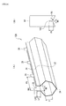
- Figs. 1(A) to 1(D) illustrate closed structure parts manufactured using methods for manufacturing a closed structure part according to embodiments of the present invention.
- Each of closed structure parts 10 to 16 is used as part of a side member of the body of, for example, a motor vehicle.
- Each of the closed structure parts 10 to 16 is formed from a metal plate (a high-tensile steel plate in the present embodiment).
- a metal plate a high-tensile steel plate in the present embodiment.
- each of the closed structure parts 10 to 16 is mounted in the vehicle so that the length direction thereof (a direction indicated by an arrow LP) is the front-rear direction of the vehicle.
- each of the closed structure parts 10 to 16 has an elongated tubular shape having an open end at either end.
- Each of the closed structure parts 10 to 16 includes a main body 18 that has a closed section extending in a direction perpendicular to the length direction.
- Flange portions 20 and 22 are integrally formed as the pair of joint ends of the main body 18.
- the main body 18 and the pair of flange portions 20 and 22 are formed from a single high-tensile steel plate by press forming.
- the main bodies 18 of the closed structure parts 10 to 16 have a variety of shapes in cross section in accordance with a required installation space and the required strength of the body of the vehicle. More specifically, for example, the main body 18 of the closed structure part 10 (refer to Fig. 1(A) ) has a substantially rectangular shape in cross section. The length direction of the shape corresponds to the left-right direction of the vehicle.
- the main body 18 of the closed structure part 12 (refer to Fig. 1(B) ) has a substantially regular hexagonal shape in cross section.
- the main body 18 of the closed structure part 14 (refer to Fig. 1(C) ) has an irregular hexagonal shape in cross section, in which the corner portions on both sides of the upper end tapers downward.
- the main body 18 of the closed structure part 16 (refer to Fig. 1(D) ) has a substantially irregular octagonal shape in cross section, in which the corner portions on both sides of the upper end portion taper downward and the corner portions on both sides of the lower end portion taper upward.
- the cross-sectional shape of the main body 18 is not limited to the shapes shown in Figs. 1(A) to 1(D) .
- the cross-sectional shape may be another polygonal shape.
- part or the entirety of the cross-sectional shape of the main body 18 can be a curved shape, such as an arc or an elliptic curve.
- the pair of flange portions 20 and 22 are formed as the upper portions of each of the closed structure parts 10 to 16 in the vertical direction (a direction indicated by an arrow HP).
- the two flange portions 20 and 22 have symmetrical shapes in the width direction (a direction indicated by an arrow WP).
- the two flange portions 20 and 22 are formed by bending either of the end portions (a pair of joint ends) of the main body 18 in a direction perpendicular to the length direction upwards.
- the pair of flange portions 20 and 22 are joined together by using a variety of welding techniques, such as spot welding, laser welding, or arc welding.
- high stiffness cap members fixedly cap the ends of the closed structure parts 10 to 16 in the length direction of the closed structure parts 10 to 16 by insertion. Thereafter, a reinforcement member for reinforcing one of the closed structure parts 10 to 16 or a bracket, a bolt, or a nut for connecting the closed structure part to the vehicle is attached to the outer periphery or the inner periphery of the closed structure part as needed. In this way, a side member, which is a component of the body of the vehicle, is manufactured.
- Figs. 2 to 4 illustrate the structures of a first press forming apparatus, a second press forming apparatus, and a hemming press apparatus used for manufacturing a closed structure part according to an embodiment of the present invention.
- Figs. 2 to 4 illustrate closed structure parts processed by these apparatuses during manufacturing.
- a first press forming apparatus 30, a second press forming apparatus 60, and a hemming press apparatus 80 shown in Figs. 2 to 4 are used for manufacturing the closed structure part 12 having a regular hexagonal shape in cross section (refer to Fig. 1(B) ).
- the first press forming apparatus 30 includes a press forming die having a die 32 and a punch 34.
- the first press forming apparatus 30 further includes a hydraulic actuator 36 serving as driving means for driving the punch 34.
- the upper surface of the die 32 serves as a concave press forming surface 38.
- a press concave portion 40 is formed so as to be indented from both ends into a concave shape.
- the cross-sectional shape of the press concave portion 40 in the width direction is substantially trapezoidal.
- the press concave portion 40 includes slope surfaces 42 at either end thereof in the width direction. The slope surfaces 42 extend upwards so as to taper outward.
- the lower surface of the punch 34 serves as a press forming surface 44.
- a press convex portion 46 that protrudes with respect to both ends in a convex shape is formed.
- the cross-sectional shape of the press convex portion 46 along the width direction is substantially trapezoidal so as to correspond to the cross-sectional shape of the press concave portion 40.
- the press convex portion 46 includes slope surfaces 48 at either end thereof in the width direction. The slope surfaces 48 correspond to the slope surfaces 42 of the press concave portion 40.
- the hydraulic actuator 36 includes a cylinder 50 and a plunger 52 disposed on the inner peripheral side of the cylinder 50.
- the cylinder 50 is fixed to a support frame (not shown) of the first press forming apparatus 30.
- the plunger 52 is supported by the cylinder 50 in a slidable manner along the height direction (a direction indicated by an arrow HM).
- the lower end of the plunger 52 is joined to the upper middle portion of the punch 34.
- the hydraulic actuator 36 moves the punch 34 between a press position (refer to Fig. 2 ) at which the press convex portion 46 of the punch 34 fits together with the press concave portion 40 of the die 32 and a standby position above the die 32.
- the second press forming apparatus 60 includes a pair of a die 62 and a punch 64 making up a press forming die.
- the second press forming apparatus 60 further includes a hydraulic actuator 66 serving as driving means for driving the punch 64.
- the die 62 has a concave blank insertion portion 67 in the upper middle portion thereof that is indented from the both ends into a substantially V shape.
- the bottom portion of the blank insertion portion 67 has two press forming surfaces 68 formed from a pair of slope surfaces that form a concave shape.
- Two blank supporting surfaces 70 extend from the edges of the concave press forming surfaces 68 upwards so as to taper outward.
- the punch 64 has a substantially rectangular shape in cross section having a length direction that coincides with the height direction (indicated by the arrow HM).
- the lower end surface of the punch 64 includes the press forming surfaces 74 that form a convex shape and that correspond to the press forming surfaces 68 that form a concave shape.
- the hydraulic actuator 66 includes a cylinder 76 and a plunger 78 disposed on the inner peripheral side of the cylinder 76.
- the cylinder 76 is fixed to a support frame (not shown) of the second press forming apparatus 60.
- the plunger 78 is supported by the cylinder 76 in a slidable manner along the height direction.
- the lower end of the plunger 78 is joined to the upper middle portion of the punch 64.
- the hydraulic actuator 66 moves the punch 64 between a press position (refer to Fig. 3 ) at which the press forming surface 74 of the punch 64 fits together with the press forming surface 68 of the die 62 and a standby position above the die 62.
- the hemming press apparatus 80 includes an insert core 82 having a cross section corresponding to the cross section of the main body 18 of the closed structure part 12 which is the final part (refer to Fig. 1(B) ).
- the hemming press apparatus 80 further includes a punch 84 disposed above the insert core 82.
- the insert core 82 and the punch 84 serve as a press forming die.
- the hemming press apparatus 80 includes a supporting pad 86 disposed beneath the insert core 82 and two pressure cams 88 disposed at either outer end of the insert core 82 in the width direction.
- the hemming press apparatus 80 includes a hydraulic actuator 90 serving as driving means for driving the punch 84 and a cam drive mechanism 92 that operates in conjunction with the hydraulic actuator 90.
- the supporting pad 86 has a blank supporting surface 94 formed from a pair of slope surfaces that form a concave shape on the upper surface side.
- the shape of the blank supporting surface 94 corresponds to the shape of a bottom plate portion 54 of the main body 18.
- the punch 84 has two press forming surfaces 96 at either end of the punch 84 in the width direction of the lower surface.
- the two press forming surfaces 96 have a shape that corresponds to the shape of a shoulder portion 26 that is an outer portion of the flange portions 20 and 22.
- the insert core 82 has, as the upper surface, a press forming surface 98 formed from slope surfaces that correspond to the two press forming surfaces 96.
- the insert core 82 has, as a bottom surface, a convex blank supporting surface 100 that corresponds to the blank supporting surface 94 of the supporting pad 86.
- the side surface of each of the pressure cams 88 on an inner side in the width direction serves as a pressure surface 89 corresponding to a side portion 83 of the insert core 82.
- the punch 84 has a slit clearance 102 in the middle portion between the two press forming surfaces 96 extending in the width direction.
- the punch 84 has an insert guide surface 104 between the slit clearance 102 and each of the two press forming surfaces 96.
- WA denote the opening width of the slit clearance 102
- DG denote the depth of the slit clearance 102 with respect to the two press forming surfaces 96.
- the opening width WA is appropriately set to a value greater than or equal to 2 times the thickness of the high-tensile steel plate that is the material used for the closed structure part 12 and less than or equal to 10 times the thickness.
- the depth DG is appropriately set to a value greater than or equal to 3 mm and less than or equal to 50 mm.
- Each of the two insert guide surfaces 104 is formed as a convex curved surface having a constant radius of curvature.
- the insert guide surface 104 smoothly connects the side end portion of the press forming surface 96 to the lower end portion of the slit clearance 102.
- RG denote the radius of curvature of the insert guide surface 104.
- the radius of curvature RG may be 0 mm (a right angle) or may have a value greater than 0.
- the radius of curvature RG can be set to any value as appropriate.
- the hydraulic actuator 90 includes a cylinder 106 and a plunger 108 disposed on the inner peripheral side of the cylinder 106.
- the cylinder 106 is fixed to a support frame (not shown) of the hemming press apparatus 80.
- the plunger 108 is supported by the cylinder 106 in a slidable manner along the height direction.
- the lower end of the plunger 108 is joined to the upper middle portion of the punch 84.
- the hydraulic actuator 90 moves the punch 84 between a press position (refer to Fig. 4(C) ) at which the press forming surface 96 of the punch 84 fits together with the press forming surface 98 of the insert core 82 and a standby position above the insert core 82.
- a pair of the cam drive mechanisms 92 operates in conjunction with the operation performed by the hydraulic actuator 90.
- Each of the cam drive mechanisms 92 moves the pressure cam 88 between a standby position (refer to Fig. 4(A) ) to which the pressure cam 88 is moved away from the side portion of the insert core 82 along the width direction and a pressure position at which the pressure cam 88 is urged against the side portion of the insert core 82 in the width direction. More specifically, when the hydraulic actuator 90 moves the punch 84 downward from the standby position to the press position, the cam drive mechanism 92 moves the pressure cam 88 from the standby position to the pressure position.
- a press forming apparatus is not limited to such an apparatus.
- a mechanical press machine i.e., a widely used press machine
- crank press can be used.
- a method for manufacturing the closed structure part 12 (a method for manufacturing a closed structure part) using the above-described manufacturing apparatus is described next.
- a first press step using the first press forming apparatus 30 shown in Fig. 2 is performed first.
- a blank 24 that is a high-tensile steel plate and that has been cut into a predetermined shape in advance is mounted between the press forming surface 38 of the die 32 and the press forming surface 44 of the punch 34 of the first press forming apparatus 30.
- the punch 34 located at the standby position is lowered to the press position using the hydraulic actuator 36. In this way, as shown in Fig.
- the blank 24 is formed into a shape corresponding to the shape formed by the press forming surface 38 and the press forming surface 44 (press forming). At that time, the flange portions 20 and 22 are formed at either end of the blank 24 in the width direction.
- the pair of shoulder portions 26 is formed in the main body 18 by the slope surfaces 42 and 48.
- a preliminary hemming step is performed using a general-purpose press forming apparatus (not shown) after the first press step has been completed.
- An example of the general-purpose press forming apparatus is a press forming apparatus that can bend the end portion of a planar high-tensile steel plate at a substantially right angle.
- a plurality of hemming prongs 28 are formed in advance in one of the side end portions of the blank 24 corresponding to the flange portion 20, which is one of the two flange portions.
- a plurality of protruding portions 27 are formed so as to correspond to the plurality of hemming prongs 28.
- the protruding portions 27 each having a rectangular shape are formed so as to protrude from the side end of the blank 24.
- PH denote the separation distance between the protruding portions 27 in the length direction
- LH denote the protruding length of the plurality of protruding portions 27 from the side end of the blank 24.
- the separation distance PH is appropriately set to a value greater than or equal to 5 mm and less than or equal to a length obtained by subtracting the hemming prong widths from the product length.
- the protruding length LH is appropriately set to a value greater than or equal to 1 time the thickness of the blank 24 and less than or equal to 1.5 times the flange height.
- a width BH is appropriately set to a value greater than or equal to twice the thickness of the plate and less than or equal to the product length.
- the plurality of protruding portions 27 that are formed in the blank 24 in the first press step shown in Fig. 2 and that protrude from the top end of the flange portion 20, which is one of the two flange portions, are bent towards the flange portion 22, which is the other flange portion, at a substantially right angle. In this way, the plurality of protruding portions 27 are made into the plurality of hemming prongs 28 used for joining (hemming-joining) the flange portions 20 and 22.
- a second press step using the second press forming apparatus 60 shown in Fig. 3 is performed after the preliminary hemming step has been completed.
- the blank 24 having the pair of shoulder portions 26 and the plurality of hemming prongs 28 formed therein through the first press step and the preliminary hemming step is mounted on the blank insertion portion 67 of the die 62 of the second press forming apparatus 60.
- the punch 64 located at the standby position is lowered to the press position by the hydraulic actuator 66.
- the middle portion of the blank 24 in the width direction is formed into a shape corresponding to the shape formed by the press forming surfaces 68 and 74 (press forming).
- the bottom plate portion 54 of the main body 18 is formed in the middle of the blank 24 in the width direction.
- a portion of the blank 24 between each of the shoulder portions 26 and the bottom plate portion 54 is made into a side plate portion 56.
- Each of the two side plate portions 56 is supported by one of the two blank supporting surfaces 70 and is bent at a predetermined tilt angle with respect to the bottom plate portion 54.
- a closing step and a press hemming step are performed using the hemming press apparatus 80 after the second press step has been completed.
- the closing step and press hemming step as shown in Fig. 4(A) , the bottom plate portion 54 of the blank 24 is sandwiched between the blank supporting surface 94 of the supporting pad 86 and the blank supporting surface 100 of the insert core 82.
- the pressure surface 89 of each of the pressure cams 88 located at the standby position is brought into contact with the blank 24 at a position in the vicinity of the border between the shoulder portions 26 and the side plate portion 56.
- each of the pressure cams 88 located at the standby position is moved towards the pressure position using the cam drive mechanism 92.
- each of the side plate portions 56 is moved (bent) towards the side portion 83 of the insert core 82 and is urged against the side portion 83 by the pressure surface 89 of the pressure cam 88.
- the punch 84 located at the standby position is lowered towards the press position by using the hydraulic actuator 90.
- the top ends of the flange portions 20 and 22 are moved towards the slit clearance 102 along the two press forming surfaces 96 and the two insertion guide surfaces of the punch 84.
- the top ends of the plurality of hemming prongs 28 are in pressure contact with the inner surface portion of the slit clearance 102.
- the hemming prongs 28 are further bent downward about the border portion with the flange portion 20 by the downward pressing force transferred via the inner surface portion of the slit clearance 102.
- each of the hemming prongs 28 sandwiches the top portion of the flange portion 22, which is the other flange portion.
- the flange portion 20 one of the two flange portions, is joined to the flange portion 22 via the plurality of hemming prongs 28 (hemming joint).
- a welding step is performed using a general-purpose welding apparatus, such as a spot welding apparatus, a laser welding apparatus, or an arc welding apparatus.
- a general-purpose welding apparatus such as a spot welding apparatus, a laser welding apparatus, or an arc welding apparatus.
- the flange portions 20 and 22 joined using the hemming prongs 28 are welded together using spot welding, laser welding, or arc welding.
- the top end of the welded portion of the flange portions 20 and 22 is cut off by shearing or meltdown in order to further reduce the weight.
- the flange portion is not cut off and can be used as a joint flange for joining another part.
- the closed structure part 12 shown in Fig. 1(B) is manufactured.
- the closed structure parts 10, 14, and 16 other than the closed structure part 12 can be manufactured through the steps that are substantially the same as those for the closed structure part 12 by simply mounting the dies 32 and 62, the punches 34, 64, and 84, the supporting pad 86, the pressure cams 88, and the insert core 82 that correspond to the shape of the closed structure part to be manufactured into the first press forming apparatus 30, the second press forming apparatus 60, and the hemming press apparatus 80 and appropriately adjusting, for example, the strokes of the hydraulic actuators 36, 66, and 90 and the cam drive mechanism 92.
- the hemming press apparatus 80 includes the insert core 82 and the punch 84 serving as a press forming die.
- the press joining apparatus 80 performs the hemming press step using the insert core 82 and the punch 84 in addition to the supporting pad 86 and the pair of pressure cams 88.
- the hemming press step press forming and hemming
- the punch 84, the supporting pad 86, and the pair of pressure cams 88 can be performed using only the punch 84, the supporting pad 86, and the pair of pressure cams 88 without using the insert core 82 in the hemming press apparatus 80 and without supporting the blank 24 by the insert core 82 from inside, as shown in Figs. 5(A) to 5(C) .
- the hemming press step of the method for manufacturing a closed structure part according to the present embodiment is described in more detail next with reference to Figs. 6 and 7 .
- the hemming press step used when the closed structure part 10 shown in Fig. 1(A) is manufactured from the blank 24 is described.
- the plurality of hemming prongs 28 protruding from the top end of the flange portion 20, which is one of the two flange portions are bent towards the flange portion 22, as shown in Figs. 7(A) and 7(B) .
- an angle ⁇ P formed by the flange portion 20 and the plurality of hemming prongs 28 be 90° or an angle slightly larger than 90°. That is, if the angle ⁇ P is smaller than 90°, the hemming prongs 28 that are preliminarily bent cannot be in the state shown in Fig. 7(D) with respect to the other flange portion 22.
- the two side plate portions 56 of the blank 24 are urged against the side portions 83 of the insert core 82 by the pressure cams 88.
- the distance between the top portions of the flange portions 20 and 22 is made smaller than a distance between the outer ends of the two insert guide surfaces 104 of the punch 84.
- the top end portions of the flange portions 20 and 22 and the hemming prongs 28 are inserted into the slit clearance 102.
- the top ends of the hemming prongs 28 are in pressure contact with the inner surface portion of the slit clearance 102 at a predetermined contact angle ⁇ C.
- the contact angle ⁇ C is larger than 90°. Accordingly, a large friction resistance occurs between each of the top ends of the hemming prongs 28 and the inner surface portion of the slit clearance 102.
- each of the two shoulder portions 26 of the blank 24 is formed into a predetermined shape by one of two press forming surfaces 96 of the punch 84 and one of the two press forming surfaces 98 of the insert core 82.
- the hemming prongs 28 are bent downwards about the border portion with the flange portion 20 due to the friction force (the pressing force) transferred from the inner surface portion of the slit clearance 102. In this way, as shown in Figs.
- each of the plurality of hemming prongs 28 sandwiches the top portion of the other flange portion 22.
- the flange portion 20, which is one of the two flange portions is joined to the other flange portion 22 via the plurality of hemming prongs 28 (hemming joint).
- the hemming press apparatus 80 raises the punch 84 from the press position to the standby position by using the hydraulic actuator 90. Thereafter, the hemming press apparatus 80 moves the insert core 82 away from the blank 24 (the main body 18) along the length direction of the closed structure part 10. In this way, the form of the closed structure part 10 having a closed section is achieved.
- the flange portions 20 and 22 of the blank 24 processed in the hemming press step are welded, and the top ends of the flange portions 20 and 22 are cut off in order to reduce the weight of the closed structure part 10.
- the closed structure part 10 serving as a component is completed.
- the blank 24 processed in the hemming press step may be directly used as a closed structure part (a finished part).
- the closing step is performed.
- the two insert guide surfaces 104 of the punch 84 are urged against the top end of the flange portion 20, and the punch 84 is lowered towards the press position.
- the flange portions 20 and 22 are brought closer to each other due to a force component generated by each of the two insert guide surfaces 104, and the flange portions 20 and 22 are guided into the slit clearance 102 of the punch 84.
- the flange portions 20 and 22 can be brought closer to each other against the deformation resistance (springback) of the blank 24, and the distance between the flange portions 20 and 22 can be set so as to correspond to the opening width WA of the slit clearance 102. Accordingly, if the opening width WA of the slit clearance 102 is appropriately determined in accordance with the allowable value for the distance between the flange portions 20 and 22, the distance between the flange portions 20 and 22 can be sufficiently reduced and can be maintained in the slit clearance 102.
- the punch 84 is further lowered towards the press position in the hemming press step.
- the flange portions 20 and 22 are inserted into the slit clearance 102 and the hemming prongs 28 are bent so as to sandwich the flange portion 22.
- the flange portion 20, which is one of the two flange portions is joined to the other flange portion 22.
- the metal plate is pressurized by the two press forming surfaces 96 of the punch 84 and, thus, the two shoulder portions 26 of the blank 24 are press-formed into a predetermined shape.
- the distance between the flange portions 20 and 22 can be sufficiently decreased. Thereafter, the flange portion 20 can be fixed to the flange portion 22 using the hemming prongs 28 (hemming joint). At the same time, the two shoulder portions 26 of the blank 24 can be press-formed into a predetermined shape.
- a single high-tensile steel plate serving as the blank 24 can be manufactured into any one of the closed structure parts 10 to 16.
- the hemming joint operation of the flange portions 20 and 22 of one of the closed structure parts 10 to 16 and the press-forming operation of the two shoulder portions 26 of the blank 24 can be performed at the same time. Accordingly, the number of sub-parts of each of the closed structure parts 10 to 16 and the number of steps for manufacturing the closed structure part can be reduced and, therefore, the closed structure parts 10 to 16 can be efficiently manufactured.
- a single metal plate serving as the blank 24 is mounted on the insert core 82 and the punch 84.
- the punch 84 is lowered from the standby position to the press position using the hydraulic actuator 90.
- the distance between the flange portions 20 and 22 can be sufficiently reduced in the slit clearance 102.
- the flange portion 20, which is one of the two flange portions can be fixed to the flange portion 22 using the hemming prongs 28 (hemming joint).
- the two shoulder portions 26 of the blank 24 can be press-formed into a predetermined shape.
- any one of the closed structure parts 10 to 16 having a closed section can be manufactured using the single metal plate serving as the blank 24.
- the hemming joint operation of the flange portions 20 and 22 of each of the closed structure parts 10 to 16 and the press-forming operation of the two shoulder portions 26 of the blank 24 can be performed at the same time. Accordingly, the number of sub-parts of each of the closed structure parts 10 to 16 and the number of steps for manufacturing the closed structure part can be reduced and, therefore, the closed structure parts 10 to 16 can be efficiently manufactured.
- the main body 18, the two flange portions 20 and 22, and the hemming prongs 28 are formed from a single high-tensile steel plate (the blank 24). Hemming is performed so that the hemming prongs 28 protruding from the top portion of the flange portion 20, which is one of the two flange portions, sandwich the other flange portion 22. Thus, the flange portion 20 is fixed to the flange portion 22 (hemming joint). In this way, the main body 18, the flange portions 20 and 22, and the hemming prongs 28, which are main components of each of the closed structure parts 10 to 16, can be integrally formed from the single blank 24.
- joint ends of the main body 18 can be joined together using only the flange portions 20 and 22 so that the main body 18 can have closed section. Accordingly, the number of sub-parts of each of the closed structure parts 10 to 16 can be reduced, and the ratio of the weight of the flange portions 20 and 22 to the entire weight of the closed structure part can be reduced, as compared with a closed structure part including two or more independent sub-parts. Thus, the weight of each of the closed structure parts 10 to 16 can be efficiently reduced.
- the opening width WA of the slit clearance 102 of the punch 84 is appropriately set to a value greater than or equal to twice the thickness of the blank 24 that is the material used for the closed structure part 10 and less than or equal to ten times the thickness. This is because if the opening width WA is set to a value less than twice the thickness of the blank 24, the friction resistance between the slit clearance 102 and each of the flange portions 20 and 22 is excessively increased when the punch 84 is lowered and, therefore, fracturing or cracking may occur in the blank 24.
- the opening width WA is set to a value greater than ten times the thickness of the blank 24, the hemming prongs 28 cannot be urged against the other flange portion 22 in hemming even if the punch 84 is lowered to the press position. Thus, a gap may be formed between the flange portions 20 and 22 (backlash may occur).
- the depth DG of the slit clearance 102 of the punch 84 is appropriately set to a value greater than or equal to 3 mm and less than or equal to 50 mm. This is because the depth DG of the slit clearance 102 needs to be greater than the protruding length of each of the flange portions 20 and 22. If the depth DG is set to a value less than 3 mm, the height of each of the flange portions 20 and 22 is too small and, thus, it is difficult to join the flange portions 20 and 22 together by welding after the hemming joint is performed. In contrast, if the depth DG is set to a value greater than 50 mm, it is difficult to maintain the stiffness of the punch 84.
- the protruding length LH of the hemming prongs 28 is appropriately set to a value greater than or equal to 1 time the thickness of the blank 24 and less than or equal to 1.5 times the flange height. This is because if the protruding length LH is less than 1 time the thickness of the blank 24, it is difficult to sufficiently increase the joint strength between the flange portions 20 and 22 that are joined using the hemming prongs 28. Thus, it is difficult to reliably join the flange portions 20 and 22 together by hemming.
- the separation distance PH of the hemming prongs 28 is appropriately set to a value greater than or equal to 5 mm and less than or equal to a length obtained by subtracting the hemming prong widths from the product length. This is because if the separation distance PH is less than 5 mm, the ratio of the weight of the plurality of hemming prongs 28 to the entire weight of each of the closed structure parts 10 to 16 is excessively increased and, therefore, the weight of each of the closed structure parts 10 to 16 is increased.
- the separation distance PH can be less than or equal to a length obtained by subtracting the length of the hemming prong from the product length.
- the helming prong width is less than 2 times the thickness of the plate, it is difficult to sufficiently increase the joint strength between the flange portions 20 and 22 and, therefore, it is difficult to reliably join the flange portions 20 and 22 together by hemming.
- the hemming prong width can be smaller than or equal to the product length.
- closed structure parts manufactured using the method for manufacturing a closed structure part according to the embodiment of the present invention are described next as embodiments 0 to 4.
- closed structure parts manufactured using a method for manufacturing a closed structure part that does not meet the conditions of the embodiment of the present invention are described below as comparative examples 1 to 4.
- a cold-rolled steel having a thickness of 1.2 mm and a tensile strength of 1180 MPa is employed as the blank 24.
- Such a blank 24 is subjected to a process performed in a hemming press step using the hemming press apparatus 80.
- a closed structure part 120 serving as an interim part is formed (press-formed).
- the closed structure part 120 has a substantially rectangular cross section.
- a width B of the closed structure part 120 is 120 mm.
- a height H of the closed structure part 120 is 80 mm.
- the entire length of the closed structure part 120 is 800 mm.
- the closed structure part 120 does not have the two flange portions and hemming prongs according to the present invention. Accordingly, even when the hemming press step is performed on the blank 24, hemming is not performed on hemming prongs. Accordingly, the presence or absence of the insert guide surface 104 and the slit clearance 102 in the punch 84 has no impact on, for example, the shape of the closed structure part 120.
- a cold-rolled steel having a thickness of 1.2 mm and a tensile strength of 1180 MPa is employed as the blank 24.
- Such a blank 24 is subjected to the processes in the closing step and hemming press step using the hemming press apparatus 80.
- a closed structure part 122 serving as an interim part is formed (press-formed).
- the closed structure part 122 has a substantially rectangular cross section.
- a width B of the closed structure part 122 is 120 mm.
- a height H of the closed structure part 122 is 80 mm.
- the entire length of the closed structure part 122 is 800 mm.
- the protruding length LF of the flange portions 20 and 22 is set to 15 mm.
- the closed structure part 122 does not have a hemming prong according to the present invention. Accordingly, when the closing step and hemming press step are performed on the blank 24, the closing process for bringing the flange portions 20 and 22 close to each other is performed. However, hemming is not performed on hemming prongs.
- the punch 84 including the slit clearance 102 having a depth DG of 30 mm and an opening width WA of 5 mm and the insert guide surfaces 104 having a radius of curvature RG of 30 mm is employed.
- a cold-rolled steel having a thickness of 1.2 mm and a tensile strength of 1180 MPa is employed as the blank 24.
- Such a blank 24 is subjected to the processes performed by the hemming press apparatus 80 in the closing step and the hemming press step.
- a closed structure part 124 serving as an interim part is formed (press-formed).
- the closed structure part 124 has a substantially rectangular cross section.
- a width B of the closed structure part 124 is 120 mm.
- a height H of the closed structure part 124 is 80 mm.
- the entire length of the closed structure part 124 is 800 mm.
- the protruding length LF of the flange portions 20 and 22 is set to 15 mm.
- the hemming prongs 28 are processed in a preliminary hemming step before the blank 24 is mounted in the hemming press apparatus 80 and are preliminary bent.
- the width BH of the hemming prong 28 is set to 10 mm.
- the protruding length LH of the hemming prongs 28 is also set to 10 mm.
- the separation distance PH of the hemming prongs 28 is set to 250 mm.
- the punch 84 including the slit clearance 102 having a depth DG of 30 mm and an opening width WA of 20 mm and the insert guide surfaces 104 having a radius of curvature RG of 30 mm is employed.
- the opening width WA is about 17 times the thickness of the blank 24. That is, the opening width WA is out of the appropriate range (the range greater than or equal to 2 times and less than or equal to 10 times the thickness of the blank 24).
- a cold-rolled steel having a thickness of 1.2 mm and a tensile strength of 180 MPa is employed as the blank 24.
- Such a blank 24 is subjected to the processes performed by the hemming press apparatus 80 in the closing step and the hemming press step.
- a closed structure part 126 serving as an interim part is formed (press-formed).
- the closed structure part 126 has a substantially rectangular cross section.
- a width B of the closed structure part 126 is 120 mm.
- a height H of the closed structure part 126 is 80 mm.
- the entire length of the closed structure part 126 is 800 mm.
- the protruding length LF of the flange portions 20 and 22 is set to 15 mm.
- the hemming prongs 28 are processed in a preliminary hemming step before the blank 24 is mounted in the hemming press apparatus 80 and are preliminary bent.
- the width BH of the hemming prong 28 is set to 10 mm.
- the protruding length LH of the hemming prongs 28 is set to 1 mm.
- the separation distance PH of the hemming prongs 28 is set to 780 mm.
- the punch 84 including the slit clearance 102 having a depth DG of 30 mm and an opening width WA of 5 mm and the insert guide surfaces 104 having a radius of curvature RG of 30 mm is employed.
- a cold-rolled steel having a thickness of 1.2 mm and a tensile strength of 1180 MPa is employed as the blank 24.
- Such a blank 24 is subjected to the processes performed by the hemming press apparatus 80 in the closing step and the hemming press step.
- a closed structure part 128 serving as an interim part is formed (press-formed).
- the closed structure part 128 has a substantially regular hexagonal cross section.
- the length of a side S of the hexagonal cross section is 40 mm.
- the entire length of the closed structure part 128 is 800 mm.
- the protruding length LF of the flange portions 20 and 22 is set to 15 mm.
- the hemming prongs 28 are processed in a preliminary hemming step before the blank 24 is mounted in the hemming press apparatus 80 and are preliminary bent.
- the width BH of the hemming prong 28 is set to 10 mm.
- the protruding length LH of the hemming prongs 28 is set to 10 mm.
- the separation distance PH of the hemming prongs 28 is set to 250 mm.
- the punch 84 including the slit clearance 102 having a depth DG of 30 mm and an opening width WA of 5 mm and the insert guide surfaces 104 having a radius of curvature RG of 1 mm is employed.
- a cold-rolled steel having a thickness of 1.2 mm and a tensile strength of 1180 MPa is employed as the blank 24.
- Such a blank 24 is subjected to the processes performed by the hemming press apparatus 80 in the closing step and the hemming press step.
- a closed structure part 130 serving as an interim part is formed (press-formed).
- the closed structure part 130 has a substantially rectangular cross section.
- a width B of the closed structure part 130 is 120 mm.
- a height H of the closed structure part 130 is 80 mm.
- the entire length of the closed structure part 130 is 800 mm.
- the protruding length LF of the flange portions 20 and 22 is set to 15 mm.
- the hemming prongs 28 are processed in a preliminary hemming step before the blank 24 is mounted in the hemming press apparatus 80 and are preliminary bent.
- the width BH of the hemming prong 28 is set to 10 mm.
- the protruding length LH of the hemming prongs 28 is also set to 10 mm.
- the separation distance PH of the hemming prongs 28 is set to 250 mm.
- the punch 84 including the slit clearance 102 having a depth DG of 30 mm and an opening width WA of 5 mm and the insert guide surfaces 104 having a radius of curvature RG of 30 mm is employed.
- a cold-rolled steel having a thickness of 1.2 mm and a tensile strength of 1180 MPa is employed as the blank 24.
- Such a blank 24 is subjected to the processes performed by the hemming press apparatus 80 in the closing step and the hemming press step.
- a closed structure part 132 serving as an interim part is formed (press-formed).
- the closed structure part 132 has a substantially regular hexagonal cross section.
- the length of a side S of the hexagonal cross section is 40 mm.
- the entire length of the closed structure part 132 is 800 mm.
- the protruding length LF of the flange portions 20 and 22 is set to 15 mm.
- the hemming prongs 28 are processed in a preliminary hemming step before the blank 24 is mounted in the hemming press apparatus 80 and are preliminary bent.
- the width BH of the hemming prong 28 is set to 10 mm.
- the protruding length LH of the hemming prongs 28 is also set to 10 mm.
- the separation distance PH of the hemming prongs 28 is set to 250 mm.
- the punch 84 including the slit clearance 102 having a depth DG of 30 mm and an opening width WA of 5 mm and the insert guide surfaces 104 having a radius of curvature RG of 30 mm is employed.
- a cold-rolled steel having a thickness of 1.2 mm and a tensile strength of 1180 MPa is employed as the blank 24.
- Such a blank 24 is subjected to the processes performed by the hemming press apparatus 80 in the closing step and the hemming press step.
- a closed structure part 134 serving as an interim part is formed (press-formed).
- the closed structure part 134 has an irregular hexagonal cross section.
- the width B of the bottom plate portion 54 of the closed structure part 134 is 120 mm.
- a width BS of a slope portion 58 that connects the side plate portion to the top plate portion is 30 mm, and a height H of the closed structure part 134 is 70 mm.
- the entire length of the closed structure part 134 is 800 mm.
- the protruding length LF of the flange portions 20 and 22 is set to 15 mm.
- the hemming prongs 28 are processed in a preliminary hemming step before the blank 24 is mounted in the hemming press apparatus 80 and are preliminary bent.
- the width BH of the hemming prong 28 is set to 10 mm.
- the protruding length LH of the hemming prongs 28 is also set to 10 mm.
- the separation distance PH of the hemming prongs 28 is set to 250 mm.
- the punch 84 including the slit clearance 102 having a depth DG of 30 mm and an opening width WA of 5 mm and the insert guide surfaces 104 having a radius of curvature RG of 30 mm is employed.
- a cold-rolled steel having a thickness of 1.2 mm and a tensile strength of 1180 MPa is employed as the blank 24.
- Such a blank 24 is subjected to the processes performed by the hemming press apparatus 80 in the closing step and the hemming press step.
- a closed structure part 136 serving as an interim part is formed (press-formed).
- the closed structure part 136 has an irregular structure part 136 is 60mm.
- Each of the width BS of a slope portion 30 and a width BN of two top plate portions 59 located outside the flange portions 20 and 22 is 30 mm.
- the protruding length LF of the flange portions 20 and 22 is set to 15 mm.
- the hemming prongs 28 are processed in a preliminary hemming step before the blank 24 is mounted in the hemming press apparatus 80 and are preliminary hemming step before the blank 24 is mounted in the hemming press apparatus 80 and are preliminary bent.
- the width BH of the hemming prong 28 is set to 10 mm.
- the protruding length LH of the hemming prongs 28 is also set to 10 mm.
- the separation distance PH of the hemming prongs 28 is set to 250 mm.
- the punch 84 including the slit clearance 102 having a depth DG of 30 mm and an opening width WA of 5 mm and the insert guide surfaces 104 having a radius of curvature RG of 30 mm is employed.
- a method evaluating the closed structure parts 120, 122, 124, and 126 according to the comparative examples and the closed structure parts 128, 130, 132, 134, and 136 according to the embodiments is described next.
- a gap distance GB (a maximum value) between the flange portions 20 and 22 (between two joint ends for the closed structure part 120) immediately before the blank 24 was subjected to a hemming press process using the hemming press apparatus 80 and a gap distance GA (a maximum value) between the flange portions 20 and 22 (between the two joint ends for the closed structure part 120) immediately after the blank 24 was subjected to the hemming press process were measured.
- the gap distance GA in order to increase the welding performance, it is desirable that the gap distance GA be minimized. If the gap distance GA is about 0.3 mm, the flange portions 20 and 22 can be reliably welded together without externally holding the flange portions 20 and 22.
Abstract
Description
- The present invention relates to a press forming method for manufacturing a closed structure part having a closed section by press-forming a metal plate using a press forming die and fixing flange portions formed at a pair of joint ends of the metal plate to each other by hemming, a press forming apparatus used for the press forming method, a closed structure part manufactured using the press forming method, and a closed structure part with welded flanges.
- For example, in order to manufacture a structural part having a closed section (a closed structure part), such as a side member or a side door of a vehicle (e.g., a motor vehicle), a plurality of sub-parts of the closed structure part are formed from a metal plate (e.g., a steel plate) using press forming (i.e., press sub-parts). Thereafter, one of the press-formed sub-parts is attached to another press sub-part, and the two press sub-parts are fixedly joined to each other by, for example, hemming or welding.
In this way, a closed structure part is manufactured from a plurality of press sub-parts. - An example of such a closed structure part is a door structure of a vehicle described in PTL 1. The door structure of a vehicle described in PTL 1 includes an inner panel and an outer panel each having a concave shape. The inner panel has, in an edge portion thereof, a hemming flange bent towards the outer panel. The hemming flange is bent so as to sandwich the edge portion of the outer panel. In this way, the inner panel is hemming-joined to the outer panel.
- In addition, PTL 2 describes a hemming machine for joining an outer panel to an inner panel by hemming (press hemming) (refer to Paragraphs [0002] and [0003] and
Figures 5 through 10 ). In order to join an outer panel to an inner panel, the hemming machine places the inner panel and the outer panel so that the inner panel and the outer panel overlap each other, brings a pre-hemming steel into contact with the top end portion of the hemming flange of the outer panel, and urges the top end portion in the diagonally downward direction so as to bend the top portion. Thereafter, the hemming machine moves the pre-hemming steel downward so as to further bend the hemming flange. The edge portion of the inner panel is sandwiched by the hemming flange of the outer panel. In this way, the outer panel is joined to the inner panel by hemming (hemming joint). - In addition, in order to manufacture a front side member, which is a closed structure part used for absorbing a shock occurring when the vehicle collides with an object, the flange portions formed for a plurality of press parts are firmly joined with one another using welding, such as spot welding, laser welding, or arc welding.
When manufacturing the above-described closed structure part having a closed section, a plurality of press sub-parts of the closed structure part are formed from, for example, a steel plate by pressing. Thereafter, the press sub-parts are placed so as to overlap one another. The flange portions of the press sub-parts are joined by hemming or welding. Thus, a plurality of press sub-parts are assembled into the closed structure part. -
- PTL 1: Japanese Unexamined Patent Application Publication No.
2007-176361 - PTL 2: Japanese Unexamined Patent Application Publication No.
5-228557 - However, in general, the weight of a closed structure part having a closed section increases as the number of press sub-parts of the closed structure part increases. That is, if the number of the press sub-parts increases, a connection flange portion is needed for each of the press sub-parts. In addition, such a flange portion needs to be formed on either end of the press sub-part with an inner space therebetween. Accordingly, as the number of the press sub-parts increases, the ratio of the weight of the flange portions to the entire weight of the closed structure part increases. As a result, the weight of the closed structure part is increased.
- In addition, such a closed structure part is manufactured through at least a press step to form a plurality of press sub-parts of the closed structure part using dedicated press forming dies and a hemming step to join the press sub-parts to one another by hemming. In recent years, in order to reduce the manufacturing cost of closed structure parts, it has been required to manufacture closed structure parts more efficiently than ever.
- Accordingly, it is an object of the present invention to provide a method and an apparatus capable of reducing the number of sub-parts of a closed structure part and the number of steps for manufacturing the closed structure part and, therefore, efficiently manufacturing the closed structure part. It is another object of the present invention to provide a lightweight closed structure part by reducing the number of sub-parts.
- According to [1] of the invention, a method for manufacturing a closed structure part having a closed section using a metal plate by press-processing the metal plate using a press forming die and fixing a pair of
flange portions hemming prong 28 protruding from a top end of theflange portion 20 towards theflange portion 22, a closing step of, after the pre-hemming step is completed, urging a pair ofinsert guide surfaces 104 formed on the press forming die against the top of the flange portion having the hemming prong therein, moving the press forming die in a predetermined pressing direction so that the two flange portions are brought closer to each other due to a force component perpendicular to the pressing direction that is generated by each of the insert guide surfaces, and guiding the pair of the flange portions into aslit clearance 102 formed between the pair of insert guide surfaces of the press forming die, and a hemming press step of, after the closing step is completed, further moving the press forming die in the pressing direction, inserting the pair of flange portions into the slit clearance, simultaneously bending thehemming prong 28 using a pressing force transferred from an inner surface portion of the slit clearance to a top portion of the hemming prong so that theother flange portion 22 is sandwiched by the hemming prong and theflange portion 20 is fixed to theflange portion 22, and, simultaneously, pressing the metal plate using a press forming surface formed outside of each of the insert guide surfaces of the press forming die and press-forming outer portions of the pair of the flange portions of the metal plate into predetermined shapes. - In the method for manufacturing a closed structure part according to [1] of the invention, after the pre-hemming step is completed, the closing step is performed. In the closing step, the pair of insert guide surfaces formed on the press forming die are urged against the top of the flange portion having the hemming prong therein. Simultaneously, the press forming die is moved in a predetermined pressing direction so that the two flange portions are brought closer to each other due to a force component perpendicular to the pressing direction that is generated by each of the insert guide surfaces, and the pair of the flange portions are guided into a slit clearance formed between the pair of insert guide surfaces of the press forming die. Thus, the pair of flange portions can be brought closer to each other against the deformation resistance (springback) of the metal plate serving as the material used for the closed structure part, and the distance between the pair of the flange portions can be set so as to correspond to the opening width of the slit clearance. Accordingly, if the opening width of the slit clearance is appropriately determined in accordance with the allowable value for the distance between the pair of flange portions, the distance between the pair of flange portions can be sufficiently reduced and can be maintained in the slit clearance.
- In addition, in the method for manufacturing a closed structure part according to [1] of the invention, after the closing step is completed, the hemming press step is performed. In the hemming press step, the press forming die is further moved in the pressing direction, and the pair of flange portions is inserted into the slit clearance. Simultaneously, the
hemming prong 28 is bent so that theflange portion 22 is sandwiched by the hemming prong and theflange portion 20 is fixed to the other flange portion. At the same time, the metal plate is pressed using a press forming surface formed outside of each of the insert guide surfaces of the press forming die, and press-forming outer portions of the pair of the flange portions of the metal plate are press-formed into predetermined shapes. Accordingly, the distance between the pair of flange portions can be sufficiently decreased. Thereafter, one of the flange portions can be fixed to the other flange portion using the hemming prong (hemming joint). At the same time, the outer portions of the pair of flange portions can be press-formed into a predetermined shape. - Therefore, according to the method for manufacturing a closed structure part described in [1] of the invention, a closed structure part having a closed section can be manufactured using a single metal plate. In addition, since an operation for hemming joint of the pair of flange portions of the closed structure part and an operation for press-forming the outer portions of the flange portions can be performed at the same time, the number of sub-parts of the closed structure part and the number of steps for manufacturing the closed structure part can be reduced and, therefore, the closed structure part can be efficiently manufactured.
- Furthermore, according to [2] of the invention, the method for manufacturing a closed structure part described in [1] of the invention is characterized by further including a welding step of, after the hemming press step is completed, fixing one of the flange portions to the other flange portion by welding.
According to [3] of the invention, a press forming apparatus for use in the method for manufacturing a closed structure part described in [1] or [2] of the invention is provided. The apparatus is characterized by including the press forming die and driving means for moving the press forming die in the pressing direction when the closing step and the hemming press step are performed. The press forming die has a pair of press forming surfaces having a shape corresponding to the outer portion of the pair of flange portions of the closed structure part, a pair of insert guide surfaces disposed on the outer sides of the press forming surfaces in a direction perpendicular to the pressing direction and oblique to the pressing direction and the direction perpendicular to the pressing direction, and the slit clearance formed between the pair of insert guide surfaces in the direction perpendicular to the pressing direction. - In the press forming apparatus used for manufacturing a closed structure part according to [3] of the invention, by mounting a single metal plate in the press forming die and moving the press forming die in a predetermined pressing direction using the driving means, the distance between the pair of flange portions can be sufficiently decreased. Thereafter, one of the flange portions can be fixed to the other flange portion using the hemming prong (hemming joint). At the same time, the outer portions of the pair of flange portions of the metal plate (the closed structure part) can be press-formed into a predetermined shape. Therefore, a closed structure part having a closed section can be manufactured from a single metal plate. In addition, since an operation for hemming joint of the pair of flange portions of the closed structure part and an operation for press-forming the outer portions of the flange portions can be performed at the same time, the number of sub-parts of the closed structure part and the number of steps for manufacturing the closed structure part can be reduced and, therefore, the closed structure part can be efficiently manufactured.
- In addition, according to [4] of the invention, the press forming apparatus used for manufacturing a closed structure part is characterized in that in the press forming apparatus used for manufacturing a closed structure part described in [3] of the invention, the depth of the slit clearance with respect to the insert guide surfaces is greater than or equal to 3 mm and less than or equal to 50 mm, and an opening width of the slit clearance in the direction perpendicular to the pressing direction is greater than or equal to 2 times a thickness of the metal plate serving as the material used for the closed structure part and less than or equal to 10 times the thickness of the metal plate.
- According to [5] of the invention, a closed structure part manufactured using the method for manufacturing a closed structure part described [1] or [2] of the invention is provided. The closed structure part is characterized by including a body having a closed section, a flange portion formed in each of a pair of joint ends of the body, and a hemming prong protruding from a top end of one of the flange portions, where the hemming prong is processed by hemming so that the one of the flange portions is fixed to the other flange portion.
- In the closed structure part according to [5] of the invention, the body, the flange portion, and the hemming prong are formed from a single metal plate. In addition, a hemming prong protruding from one of a top end of the flange portions is processed by hemming so that the one of the flange portions is fixed to the other flange portion. Thus, one of the flange portions is fixed to the other flange portion (hemming joint). In this way, the body, the pair of flange portions, and the flange prong, which are main components of the closed structure part, are integrally formed from a single metal plate. In addition, by joining the joint ends of the body with each other using only the pair of flange portions, the body can have a closed section. Accordingly, the number of sub-parts of the closed structure part can be reduced, and the ratio of the weight of the flange portions to the entire weight of the closed structure part can be reduced, as compared with a closed structure part including two or more independent sub-parts. Thus, the weight of the closed structure part can be efficiently reduced.
- In addition, according to [6] of the invention, a closed structure part is characterized in that in the closed structure part described in [5] of the invention, a plurality of the hemming prongs are provided in the one of the flange portions in a width direction of the flange portion with a predetermined separation distance PH therebetween, and a width of each of the hemming prongs is set to a value greater than or equal to 2 times a thickness of the metal plate and less than or equal to a product length of the closed structure part. A protruding length of the hemming prong from the top end of the flange portion is set to a value greater than or equal to 1 time the thickness of the metal plate serving as the material used for the closed structure part and less than or equal to 1.5 times a flange height, and the separation distance PH is set to a value greater than or equal to 5 mm and less than or equal to a value obtained by subtracting the widths of the hemming prongs from the product length.
- As described above, according to the present invention, a method for manufacturing a closed structure part and a press forming apparatus used for manufacturing a closed structure part can reduce the number of sub-parts of the closed structure part and the number of Manufacturing steps. As a result, a closed structure part can be efficiently manufactured.
In addition, according to the present invention, the number of sub-parts of the closed structure part can be reduced and, thus, the weight of the closed structure part can be reduced. -
- [
Fig. 1] Fig. 1 is a perspective view of a closed structure part manufactured using a method for manufacturing a closed structure part according to an embodiment of the present invention. - [
Fig. 2] Fig. 2 is a front view of a first press forming apparatus which is an apparatus for manufacturing the closed structure part according to the embodiment of the present invention. - [
Fig. 3] Fig. 3 is a front view of a second press forming apparatus which is an apparatus for manufacturing the closed structure part according to the embodiment of the present invention. - [
Fig. 4] Fig. 4 is a front view of a hemming press apparatus which is an apparatus for manufacturing the closed structure part according to the embodiment of the present invention. - [
Fig. 5] Fig. 5 is a front view of a modification of the hemming press apparatus which is an apparatus for manufacturing the closed structure part according to the embodiment of the present invention. - [
Fig. 6] Fig. 6 is a front view of an insert core and a punch used in a hemming press step performed by the hemming press apparatus according to the embodiment of the present invention. - [
Fig. 7] Fig. 7 is a front view and a side view of the structures of a flange portion and a hemming prong of a closed structure part according to the embodiment of the present invention. - [
Fig. 8] Fig. 8 is a perspective view and a front view illustrating the structure of a closed structure part and a punch according to Embodiment 1. - [
Fig. 9] Fig. 9 is a perspective view and a front view illustrating the structure of a closed structure part and a punch according to Embodiment 2. - [
Fig. 10] Fig. 10 is a perspective view illustrating the structure of a closed structure part according to Comparative Example 1. - [
Fig. 11] Fig. 11 is a perspective view and a front view illustrating the structure of a closed structure part and a punch according to Comparative Example 2. - [
Fig. 12] Fig. 12 is a perspective view and a front view illustrating the structure of a closed structure part and a punch according to Comparative Example 3. - [
Fig. 13] Fig. 13 is a perspective view and a front view illustrating the structure of a closed structure part and a punch according to Comparative Example 4. - [
Fig. 14] Fig. 14 is a perspective view and a front view illustrating the structure of a closed structure part and a punch according to Embodiment 0. - [
Fig. 15] Fig. 15 is a perspective view and a front view illustrating the structure of a closed structure part and a punch according to Embodiment 3. - [
Fig. 16] Fig. 16 is a perspective view and a front view illustrating the structure of a closed structure part and a punch according to Embodiment 4. - A method for manufacturing a closed structure part, a manufacturing apparatus used in the method, and the closed structure part manufactured using the method according to an embodiment of the present invention are described below with reference to the accompanying drawings.
-
Figs. 1(A) to 1(D) illustrate closed structure parts manufactured using methods for manufacturing a closed structure part according to embodiments of the present invention. Each ofclosed structure parts 10 to 16 is used as part of a side member of the body of, for example, a motor vehicle. Each of theclosed structure parts 10 to 16 is formed from a metal plate (a high-tensile steel plate in the present embodiment). As shown inFigs. 1(A) to 1(D) , each of theclosed structure parts 10 to 16 is mounted in the vehicle so that the length direction thereof (a direction indicated by an arrow LP) is the front-rear direction of the vehicle. In addition, each of theclosed structure parts 10 to 16 has an elongated tubular shape having an open end at either end. - Each of the
closed structure parts 10 to 16 includes amain body 18 that has a closed section extending in a direction perpendicular to the length direction.Flange portions main body 18. Themain body 18 and the pair offlange portions
Themain bodies 18 of theclosed structure parts 10 to 16 have a variety of shapes in cross section in accordance with a required installation space and the required strength of the body of the vehicle. More specifically, for example, themain body 18 of the closed structure part 10 (refer toFig. 1(A) ) has a substantially rectangular shape in cross section. The length direction of the shape corresponds to the left-right direction of the vehicle. In addition, themain body 18 of the closed structure part 12 (refer toFig. 1(B) ) has a substantially regular hexagonal shape in cross section. Furthermore, themain body 18 of the closed structure part 14 (refer toFig. 1(C) ) has an irregular hexagonal shape in cross section, in which the corner portions on both sides of the upper end tapers downward. Still furthermore, themain body 18 of the closed structure part 16 (refer toFig. 1(D) ) has a substantially irregular octagonal shape in cross section, in which the corner portions on both sides of the upper end portion taper downward and the corner portions on both sides of the lower end portion taper upward. - Note that the cross-sectional shape of the
main body 18 is not limited to the shapes shown inFigs. 1(A) to 1(D) . For example, the cross-sectional shape may be another polygonal shape. Alternatively, part or the entirety of the cross-sectional shape of themain body 18 can be a curved shape, such as an arc or an elliptic curve.
The pair offlange portions closed structure parts 10 to 16 in the vertical direction (a direction indicated by an arrow HP). The twoflange portions flange portions main body 18 in a direction perpendicular to the length direction upwards. In the states (finished states) indicated byFigs. 1(A) to 1(D) , the pair offlange portions - In order to manufacture a side member using one of such
closed structure parts 10 to 16, high stiffness cap members fixedly cap the ends of theclosed structure parts 10 to 16 in the length direction of theclosed structure parts 10 to 16 by insertion. Thereafter, a reinforcement member for reinforcing one of theclosed structure parts 10 to 16 or a bracket, a bolt, or a nut for connecting the closed structure part to the vehicle is attached to the outer periphery or the inner periphery of the closed structure part as needed. In this way, a side member, which is a component of the body of the vehicle, is manufactured. -
Figs. 2 to 4 illustrate the structures of a first press forming apparatus, a second press forming apparatus, and a hemming press apparatus used for manufacturing a closed structure part according to an embodiment of the present invention. In addition,Figs. 2 to 4 illustrate closed structure parts processed by these apparatuses during manufacturing. Note that a firstpress forming apparatus 30, a secondpress forming apparatus 60, and a hemmingpress apparatus 80 shown inFigs. 2 to 4 , respectively, are used for manufacturing theclosed structure part 12 having a regular hexagonal shape in cross section (refer toFig. 1(B) ). - As shown in
Fig. 2 , the firstpress forming apparatus 30 includes a press forming die having a die 32 and apunch 34. The firstpress forming apparatus 30 further includes ahydraulic actuator 36 serving as driving means for driving thepunch 34. The upper surface of the die 32 serves as a concavepress forming surface 38. In the middle of the concavepress forming surface 38 in the width direction (a direction indicated by an arrow WM), a pressconcave portion 40 is formed so as to be indented from both ends into a concave shape. The cross-sectional shape of the pressconcave portion 40 in the width direction is substantially trapezoidal. The pressconcave portion 40 includes slope surfaces 42 at either end thereof in the width direction. The slope surfaces 42 extend upwards so as to taper outward. - The lower surface of the
punch 34 serves as apress forming surface 44. In the middle of thepress forming surface 44 in the width direction (a direction indicated by an arrow WM), a pressconvex portion 46 that protrudes with respect to both ends in a convex shape is formed. The cross-sectional shape of the pressconvex portion 46 along the width direction is substantially trapezoidal so as to correspond to the cross-sectional shape of the pressconcave portion 40. The pressconvex portion 46 includes slope surfaces 48 at either end thereof in the width direction. The slope surfaces 48 correspond to the slope surfaces 42 of the pressconcave portion 40. - The
hydraulic actuator 36 includes acylinder 50 and aplunger 52 disposed on the inner peripheral side of thecylinder 50. Thecylinder 50 is fixed to a support frame (not shown) of the firstpress forming apparatus 30. Theplunger 52 is supported by thecylinder 50 in a slidable manner along the height direction (a direction indicated by an arrow HM). The lower end of theplunger 52 is joined to the upper middle portion of thepunch 34. Under hydraulic control of a hydraulic control unit (not shown), thehydraulic actuator 36 moves thepunch 34 between a press position (refer toFig. 2 ) at which the pressconvex portion 46 of thepunch 34 fits together with the pressconcave portion 40 of thedie 32 and a standby position above thedie 32. - As shown in
Fig. 3 , like the firstpress forming apparatus 30, the secondpress forming apparatus 60 includes a pair of adie 62 and apunch 64 making up a press forming die. The secondpress forming apparatus 60 further includes ahydraulic actuator 66 serving as driving means for driving thepunch 64. Thedie 62 has a concaveblank insertion portion 67 in the upper middle portion thereof that is indented from the both ends into a substantially V shape. The bottom portion of theblank insertion portion 67 has twopress forming surfaces 68 formed from a pair of slope surfaces that form a concave shape. Two blank supportingsurfaces 70 extend from the edges of the concavepress forming surfaces 68 upwards so as to taper outward. - The
punch 64 has a substantially rectangular shape in cross section having a length direction that coincides with the height direction (indicated by the arrow HM). The lower end surface of thepunch 64 includes thepress forming surfaces 74 that form a convex shape and that correspond to thepress forming surfaces 68 that form a concave shape.
Thehydraulic actuator 66 includes acylinder 76 and aplunger 78 disposed on the inner peripheral side of thecylinder 76. Thecylinder 76 is fixed to a support frame (not shown) of the secondpress forming apparatus 60. Theplunger 78 is supported by thecylinder 76 in a slidable manner along the height direction. The lower end of theplunger 78 is joined to the upper middle portion of thepunch 64. Under hydraulic control of a hydraulic control unit (not shown), thehydraulic actuator 66 moves thepunch 64 between a press position (refer toFig. 3 ) at which thepress forming surface 74 of thepunch 64 fits together with thepress forming surface 68 of thedie 62 and a standby position above thedie 62. - As shown in
Fig. 4(A) , the hemmingpress apparatus 80 includes aninsert core 82 having a cross section corresponding to the cross section of themain body 18 of theclosed structure part 12 which is the final part (refer toFig. 1(B) ). The hemmingpress apparatus 80 further includes apunch 84 disposed above theinsert core 82. Theinsert core 82 and thepunch 84 serve as a press forming die. Furthermore, the hemmingpress apparatus 80 includes a supportingpad 86 disposed beneath theinsert core 82 and twopressure cams 88 disposed at either outer end of theinsert core 82 in the width direction. Still furthermore, the hemmingpress apparatus 80 includes ahydraulic actuator 90 serving as driving means for driving thepunch 84 and acam drive mechanism 92 that operates in conjunction with thehydraulic actuator 90. - The supporting
pad 86 has a blank supportingsurface 94 formed from a pair of slope surfaces that form a concave shape on the upper surface side. The shape of the blank supportingsurface 94 corresponds to the shape of abottom plate portion 54 of themain body 18. In addition, thepunch 84 has twopress forming surfaces 96 at either end of thepunch 84 in the width direction of the lower surface. The twopress forming surfaces 96 have a shape that corresponds to the shape of ashoulder portion 26 that is an outer portion of theflange portions - In contrast, the
insert core 82 has, as the upper surface, apress forming surface 98 formed from slope surfaces that correspond to the two press forming surfaces 96. In addition, theinsert core 82 has, as a bottom surface, a convex blank supportingsurface 100 that corresponds to the blank supportingsurface 94 of the supportingpad 86. In addition, the side surface of each of thepressure cams 88 on an inner side in the width direction serves as apressure surface 89 corresponding to aside portion 83 of theinsert core 82. - As shown in
Fig. 6(A) or9(B) , thepunch 84 has aslit clearance 102 in the middle portion between the twopress forming surfaces 96 extending in the width direction. In addition, thepunch 84 has aninsert guide surface 104 between theslit clearance 102 and each of the two press forming surfaces 96. Here, let WA denote the opening width of theslit clearance 102 and let DG denote the depth of theslit clearance 102 with respect to the two press forming surfaces 96. Then, according to the present embodiment, the opening width WA is appropriately set to a value greater than or equal to 2 times the thickness of the high-tensile steel plate that is the material used for theclosed structure part 12 and less than or equal to 10 times the thickness. In addition, the depth DG is appropriately set to a value greater than or equal to 3 mm and less than or equal to 50 mm. - Each of the two insert guide surfaces 104 is formed as a convex curved surface having a constant radius of curvature. The
insert guide surface 104 smoothly connects the side end portion of thepress forming surface 96 to the lower end portion of theslit clearance 102. Here, let RG denote the radius of curvature of theinsert guide surface 104. Then, the radius of curvature RG may be 0 mm (a right angle) or may have a value greater than 0. The radius of curvature RG can be set to any value as appropriate.
Thehydraulic actuator 90 includes acylinder 106 and aplunger 108 disposed on the inner peripheral side of thecylinder 106. Thecylinder 106 is fixed to a support frame (not shown) of the hemmingpress apparatus 80. Theplunger 108 is supported by thecylinder 106 in a slidable manner along the height direction. The lower end of theplunger 108 is joined to the upper middle portion of thepunch 84. Under hydraulic control of a hydraulic control unit (not shown), thehydraulic actuator 90 moves thepunch 84 between a press position (refer toFig. 4(C) ) at which thepress forming surface 96 of thepunch 84 fits together with thepress forming surface 98 of theinsert core 82 and a standby position above theinsert core 82. - A pair of the
cam drive mechanisms 92 operates in conjunction with the operation performed by thehydraulic actuator 90. Each of thecam drive mechanisms 92 moves thepressure cam 88 between a standby position (refer toFig. 4(A) ) to which thepressure cam 88 is moved away from the side portion of theinsert core 82 along the width direction and a pressure position at which thepressure cam 88 is urged against the side portion of theinsert core 82 in the width direction. More specifically, when thehydraulic actuator 90 moves thepunch 84 downward from the standby position to the press position, thecam drive mechanism 92 moves thepressure cam 88 from the standby position to the pressure position. In contrast, when thehydraulic actuator 90 moves thepunch 84 upward from the press position to the standby position, thecam drive mechanism 92 moves thepressure cam 88 from the pressure position to the standby position.
While the above-described apparatus shown inFigs. 2 to 5 has been described as a press forming apparatus that moves the punch using a hydraulic actuator, a press forming apparatus according to the present invention is not limited to such an apparatus. For example, a mechanical press machine (i.e., a widely used press machine) including a crank press can be used. - A method for manufacturing the closed structure part 12 (a method for manufacturing a closed structure part) using the above-described manufacturing apparatus is described next.
In a method for manufacturing a closed structure part according to the present embodiment, a first press step using the firstpress forming apparatus 30 shown inFig. 2 is performed first. In the first press step, a blank 24 that is a high-tensile steel plate and that has been cut into a predetermined shape in advance is mounted between thepress forming surface 38 of thedie 32 and thepress forming surface 44 of thepunch 34 of the firstpress forming apparatus 30. Thereafter, thepunch 34 located at the standby position is lowered to the press position using thehydraulic actuator 36. In this way, as shown inFig. 2 , the blank 24 is formed into a shape corresponding to the shape formed by thepress forming surface 38 and the press forming surface 44 (press forming). At that time, theflange portions shoulder portions 26 is formed in themain body 18 by the slope surfaces 42 and 48. - In the method for manufacturing a closed structure part according to the present embodiment, a preliminary hemming step is performed using a general-purpose press forming apparatus (not shown) after the first press step has been completed. An example of the general-purpose press forming apparatus is a press forming apparatus that can bend the end portion of a planar high-tensile steel plate at a substantially right angle. In addition, as shown in
Fig. 9 (A) , a plurality of hemmingprongs 28 are formed in advance in one of the side end portions of the blank 24 corresponding to theflange portion 20, which is one of the two flange portions. A plurality of protrudingportions 27 are formed so as to correspond to the plurality of hemming prongs 28. As shown inFig. 2 , the protrudingportions 27 each having a rectangular shape are formed so as to protrude from the side end of the blank 24. - Here, let PH denote the separation distance between the protruding
portions 27 in the length direction and let LH denote the protruding length of the plurality of protrudingportions 27 from the side end of the blank 24. The separation distance PH is appropriately set to a value greater than or equal to 5 mm and less than or equal to a length obtained by subtracting the hemming prong widths from the product length. In addition, the protruding length LH is appropriately set to a value greater than or equal to 1 time the thickness of the blank 24 and less than or equal to 1.5 times the flange height. Furthermore, a width BH is appropriately set to a value greater than or equal to twice the thickness of the plate and less than or equal to the product length. - In the preliminary hemming step (not shown), the plurality of protruding
portions 27 that are formed in the blank 24 in the first press step shown inFig. 2 and that protrude from the top end of theflange portion 20, which is one of the two flange portions, are bent towards theflange portion 22, which is the other flange portion, at a substantially right angle. In this way, the plurality of protrudingportions 27 are made into the plurality of hemmingprongs 28 used for joining (hemming-joining) theflange portions
In the method for manufacturing a closed structure part according to the present embodiment, a second press step using the secondpress forming apparatus 60 shown inFig. 3 is performed after the preliminary hemming step has been completed. In the second press step, the blank 24 having the pair ofshoulder portions 26 and the plurality of hemmingprongs 28 formed therein through the first press step and the preliminary hemming step is mounted on theblank insertion portion 67 of thedie 62 of the secondpress forming apparatus 60. Thereafter, thepunch 64 located at the standby position is lowered to the press position by thehydraulic actuator 66. In this way, as shown inFig. 3 , the middle portion of the blank 24 in the width direction is formed into a shape corresponding to the shape formed by thepress forming surfaces 68 and 74 (press forming). At that time, thebottom plate portion 54 of themain body 18 is formed in the middle of the blank 24 in the width direction. In addition, a portion of the blank 24 between each of theshoulder portions 26 and thebottom plate portion 54 is made into aside plate portion 56. Each of the twoside plate portions 56 is supported by one of the two blank supportingsurfaces 70 and is bent at a predetermined tilt angle with respect to thebottom plate portion 54. - In the method for manufacturing a closed structure part according to the present embodiment, a closing step and a press hemming step are performed using the
hemming press apparatus 80 after the second press step has been completed. In the closing step and press hemming step, as shown inFig. 4(A) , thebottom plate portion 54 of the blank 24 is sandwiched between the blank supportingsurface 94 of the supportingpad 86 and the blank supportingsurface 100 of theinsert core 82. At that time, thepressure surface 89 of each of thepressure cams 88 located at the standby position is brought into contact with the blank 24 at a position in the vicinity of the border between theshoulder portions 26 and theside plate portion 56. - Subsequently, as shown in
Fig. 4(B) , each of thepressure cams 88 located at the standby position is moved towards the pressure position using thecam drive mechanism 92. Thus, each of theside plate portions 56 is moved (bent) towards theside portion 83 of theinsert core 82 and is urged against theside portion 83 by thepressure surface 89 of thepressure cam 88. At the same time, thepunch 84 located at the standby position is lowered towards the press position by using thehydraulic actuator 90. The top ends of theflange portions slit clearance 102 along the twopress forming surfaces 96 and the two insertion guide surfaces of thepunch 84. - As shown in
Fig. 4(C) , when each of the twopressure cams 88 is moved to the pressure position and if each of the twoside plate portions 56 is urged against theside portion 83 of theinsert core 82 by one of the two pressure surfaces 89, theflange portions punch 84 located between the standby position and the press position is lowered to the press position by thehydraulic actuator 90. In this way, the plurality of hemmingprongs 28 and theflange portions slit clearance 102. At that time, upon being inserted into theslit clearance 102, the top ends of the plurality of hemmingprongs 28 are in pressure contact with the inner surface portion of theslit clearance 102. Thus, as thepunch 84 is further lowered, the hemming prongs 28 are further bent downward about the border portion with theflange portion 20 by the downward pressing force transferred via the inner surface portion of theslit clearance 102. In this way, each of the hemming prongs 28 sandwiches the top portion of theflange portion 22, which is the other flange portion. As a result, theflange portion 20, one of the two flange portions, is joined to theflange portion 22 via the plurality of hemming prongs 28 (hemming joint). - In the method for manufacturing a closed structure part according to the present embodiment, after the hemming press step has been completed, a welding step is performed using a general-purpose welding apparatus, such as a spot welding apparatus, a laser welding apparatus, or an arc welding apparatus. During the welding step, the
flange portions flange portions closed structure part 12 shown inFig. 1(B) is manufactured. - Note that the
closed structure parts closed structure part 12 can be manufactured through the steps that are substantially the same as those for theclosed structure part 12 by simply mounting the dies 32 and 62, thepunches pad 86, thepressure cams 88, and theinsert core 82 that correspond to the shape of the closed structure part to be manufactured into the firstpress forming apparatus 30, the secondpress forming apparatus 60, and the hemmingpress apparatus 80 and appropriately adjusting, for example, the strokes of thehydraulic actuators cam drive mechanism 92. - In addition, according to the present embodiment, as shown in
Figs. 4(A) to 4(C) , the hemmingpress apparatus 80 includes theinsert core 82 and thepunch 84 serving as a press forming die. Thepress joining apparatus 80 performs the hemming press step using theinsert core 82 and thepunch 84 in addition to the supportingpad 86 and the pair ofpressure cams 88. However, if slightly low dimension accuracy and a slightly low accuracy of the shape of theclosed structure parts 10 to 16 are allowed or if the blank 24 having an excellent plastic formability is used, the hemming press step (press forming and hemming) can be performed using only thepunch 84, the supportingpad 86, and the pair ofpressure cams 88 without using theinsert core 82 in the hemmingpress apparatus 80 and without supporting the blank 24 by theinsert core 82 from inside, as shown inFigs. 5(A) to 5(C) . - The hemming press step of the method for manufacturing a closed structure part according to the present embodiment is described in more detail next with reference to
Figs. 6 and7 . Note that in this example, the hemming press step used when theclosed structure part 10 shown inFig. 1(A) is manufactured from the blank 24 is described.
As described above, through the preliminary hemming step, the plurality of hemmingprongs 28 protruding from the top end of theflange portion 20, which is one of the two flange portions, are bent towards theflange portion 22, as shown inFigs. 7(A) and 7(B) . At that time, it is desirable that an angle θP formed by theflange portion 20 and the plurality of hemmingprongs 28 be 90° or an angle slightly larger than 90°. That is, if the angle θP is smaller than 90°, the hemming prongs 28 that are preliminarily bent cannot be in the state shown inFig. 7(D) with respect to theother flange portion 22. - In the closing step and the hemming press step, as shown in
Fig. 6(A) , before thepress forming surfaces 96 of thepunch 84 are brought into contact with the blank 24, the twoside plate portions 56 of the blank 24 are urged against theside portions 83 of theinsert core 82 by thepressure cams 88. Thus, the distance between the top portions of theflange portions punch 84. - Subsequently, as shown in
Fig. 6(B) , when thepunch 84 is lowered by thehydraulic actuator 90, the top end of theflange portion 20 is brought into contact with the two insert guide surfaces 104 and, thus, receives a pressing force from theinsert guide surface 104. At that time, since theinsert guide surface 104 is tilted with respect to a direction in which thepunch 84 moves (a pressing direction) and the width direction (a direction perpendicular to the pressing direction), a force component acts on the top portions of theflange portions flange portions - As shown in
Fig. 6(D) , if thepunch 84 is further lowered, the top end portions of theflange portions slit clearance 102. At that time, the top ends of the hemming prongs 28 are in pressure contact with the inner surface portion of theslit clearance 102 at a predetermined contact angle θC. At that time, the contact angle θC is larger than 90°. Accordingly, a large friction resistance occurs between each of the top ends of the hemming prongs 28 and the inner surface portion of theslit clearance 102. - As shown in
Fig. 6(E) , if thepunch 84 is lowered from the position shown inFig. 6(D) to the press position, each of the twoshoulder portions 26 of the blank 24 is formed into a predetermined shape by one of twopress forming surfaces 96 of thepunch 84 and one of the twopress forming surfaces 98 of theinsert core 82. At the same time, the hemming prongs 28 are bent downwards about the border portion with theflange portion 20 due to the friction force (the pressing force) transferred from the inner surface portion of theslit clearance 102. In this way, as shown inFigs. 7(C) and 7(D) , each of the plurality of hemmingprongs 28 sandwiches the top portion of theother flange portion 22. Thus, theflange portion 20, which is one of the two flange portions, is joined to theother flange portion 22 via the plurality of hemming prongs 28 (hemming joint). - If the
flange portions press apparatus 80, as shown in Fig. 6(F), raises thepunch 84 from the press position to the standby position by using thehydraulic actuator 90. Thereafter, the hemmingpress apparatus 80 moves theinsert core 82 away from the blank 24 (the main body 18) along the length direction of theclosed structure part 10. In this way, the form of theclosed structure part 10 having a closed section is achieved. According to the present embodiment, theflange portions flange portions closed structure part 10. Thus, manufacturing of theclosed structure part 10 serving as a component is completed. However, if the closed structure part is used as a structural part that does not receive an excessive load or as a part that may be deformed or destroyed, the blank 24 processed in the hemming press step may be directly used as a closed structure part (a finished part). - In the method for manufacturing a closed structure part according to the present embodiment, after the preliminary hemming step has been completed, the closing step is performed. In the closing step, the two insert guide surfaces 104 of the
punch 84 are urged against the top end of theflange portion 20, and thepunch 84 is lowered towards the press position. Thus, theflange portions flange portions slit clearance 102 of thepunch 84. In this way, theflange portions flange portions slit clearance 102. Accordingly, if the opening width WA of theslit clearance 102 is appropriately determined in accordance with the allowable value for the distance between theflange portions flange portions slit clearance 102. - In addition, in the method for manufacturing a closed structure part according to the present embodiment, after the closing step has been completed, the
punch 84 is further lowered towards the press position in the hemming press step. Thus, theflange portions slit clearance 102 and the hemming prongs 28 are bent so as to sandwich theflange portion 22. In this way, theflange portion 20, which is one of the two flange portions, is joined to theother flange portion 22. At the same time, the metal plate is pressurized by the twopress forming surfaces 96 of thepunch 84 and, thus, the twoshoulder portions 26 of the blank 24 are press-formed into a predetermined shape. Accordingly, the distance between theflange portions flange portion 20 can be fixed to theflange portion 22 using the hemming prongs 28 (hemming joint). At the same time, the twoshoulder portions 26 of the blank 24 can be press-formed into a predetermined shape. - Thus, in the method for manufacturing a closed structure part according to the present embodiment, a single high-tensile steel plate serving as the blank 24 can be manufactured into any one of the
closed structure parts 10 to 16. In addition, the hemming joint operation of theflange portions closed structure parts 10 to 16 and the press-forming operation of the twoshoulder portions 26 of the blank 24 can be performed at the same time. Accordingly, the number of sub-parts of each of theclosed structure parts 10 to 16 and the number of steps for manufacturing the closed structure part can be reduced and, therefore, theclosed structure parts 10 to 16 can be efficiently manufactured. - In addition, according to the hemming
press apparatus 80, which is an apparatus for manufacturing the closed structure part according to the present embodiment, a single metal plate serving as the blank 24 is mounted on theinsert core 82 and thepunch 84. Thepunch 84 is lowered from the standby position to the press position using thehydraulic actuator 90. Thus, the distance between theflange portions slit clearance 102. Thereafter, theflange portion 20, which is one of the two flange portions, can be fixed to theflange portion 22 using the hemming prongs 28 (hemming joint). At the same time, the twoshoulder portions 26 of the blank 24 can be press-formed into a predetermined shape. Accordingly, any one of theclosed structure parts 10 to 16 having a closed section can be manufactured using the single metal plate serving as the blank 24. In addition, the hemming joint operation of theflange portions closed structure parts 10 to 16 and the press-forming operation of the twoshoulder portions 26 of the blank 24 can be performed at the same time. Accordingly, the number of sub-parts of each of theclosed structure parts 10 to 16 and the number of steps for manufacturing the closed structure part can be reduced and, therefore, theclosed structure parts 10 to 16 can be efficiently manufactured. - Furthermore, according to one of the
closed structure parts 10 to 16 according to the present embodiment, themain body 18, the twoflange portions flange portion 20, which is one of the two flange portions, sandwich theother flange portion 22. Thus, theflange portion 20 is fixed to the flange portion 22 (hemming joint). In this way, themain body 18, theflange portions closed structure parts 10 to 16, can be integrally formed from the single blank 24. In addition, joint ends of themain body 18 can be joined together using only theflange portions main body 18 can have closed section. Accordingly, the number of sub-parts of each of theclosed structure parts 10 to 16 can be reduced, and the ratio of the weight of theflange portions closed structure parts 10 to 16 can be efficiently reduced. - The dimensions of the main components of the
punch 84 of the hemmingpress apparatus 80 according to the embodiment of the present invention and the reason for selecting the dimensions are described next as an embodiment.
As described above, the opening width WA of theslit clearance 102 of thepunch 84 is appropriately set to a value greater than or equal to twice the thickness of the blank 24 that is the material used for theclosed structure part 10 and less than or equal to ten times the thickness. This is because if the opening width WA is set to a value less than twice the thickness of the blank 24, the friction resistance between theslit clearance 102 and each of theflange portions punch 84 is lowered and, therefore, fracturing or cracking may occur in the blank 24. In contrast, if the opening width WA is set to a value greater than ten times the thickness of the blank 24, the hemming prongs 28 cannot be urged against theother flange portion 22 in hemming even if thepunch 84 is lowered to the press position. Thus, a gap may be formed between theflange portions 20 and 22 (backlash may occur). - In addition, the depth DG of the
slit clearance 102 of thepunch 84 is appropriately set to a value greater than or equal to 3 mm and less than or equal to 50 mm. This is because the depth DG of theslit clearance 102 needs to be greater than the protruding length of each of theflange portions flange portions flange portions punch 84. - The dimensions of the hemming prongs 28 of each of the
closed structure parts 10 to 16 according to the embodiment of the present invention and the reason for selecting the dimensions are described next as an embodiment.
As described above, the protruding length LH of the hemming prongs 28 is appropriately set to a value greater than or equal to 1 time the thickness of the blank 24 and less than or equal to 1.5 times the flange height. This is because if the protruding length LH is less than 1 time the thickness of the blank 24, it is difficult to sufficiently increase the joint strength between theflange portions flange portions closed structure parts 10 to 16 becomes too large. Thus, the weight of each of theclosed structure parts 10 to 16 is disadvantageously increased. - In addition, the separation distance PH of the hemming prongs 28 is appropriately set to a value greater than or equal to 5 mm and less than or equal to a length obtained by subtracting the hemming prong widths from the product length. This is because if the separation distance PH is less than 5 mm, the ratio of the weight of the plurality of hemming
prongs 28 to the entire weight of each of theclosed structure parts 10 to 16 is excessively increased and, therefore, the weight of each of theclosed structure parts 10 to 16 is increased. In addition, the separation distance PH can be less than or equal to a length obtained by subtracting the length of the hemming prong from the product length.
If the helming prong width is less than 2 times the thickness of the plate, it is difficult to sufficiently increase the joint strength between theflange portions flange portions - Closed structure parts manufactured using the method for manufacturing a closed structure part according to the embodiment of the present invention are described next as embodiments 0 to 4. In addition, closed structure parts manufactured using a method for manufacturing a closed structure part that does not meet the conditions of the embodiment of the present invention are described below as comparative examples 1 to 4.
In comparative example 1, a cold-rolled steel having a thickness of 1.2 mm and a tensile strength of 1180 MPa is employed as the blank 24. Such a blank 24 is subjected to a process performed in a hemming press step using thehemming press apparatus 80. Thus, as shown inFig. 10 , aclosed structure part 120 serving as an interim part is formed (press-formed). - The
closed structure part 120 has a substantially rectangular cross section. A width B of theclosed structure part 120 is 120 mm. A height H of theclosed structure part 120 is 80 mm. The entire length of theclosed structure part 120 is 800 mm. However, theclosed structure part 120 does not have the two flange portions and hemming prongs according to the present invention. Accordingly, even when the hemming press step is performed on the blank 24, hemming is not performed on hemming prongs. Accordingly, the presence or absence of theinsert guide surface 104 and theslit clearance 102 in thepunch 84 has no impact on, for example, the shape of theclosed structure part 120. - In addition, in comparative example 2, a cold-rolled steel having a thickness of 1.2 mm and a tensile strength of 1180 MPa is employed as the blank 24. Such a blank 24 is subjected to the processes in the closing step and hemming press step using the
hemming press apparatus 80. Thus, as shown inFig. 11(A) , aclosed structure part 122 serving as an interim part is formed (press-formed).
Theclosed structure part 122 has a substantially rectangular cross section. A width B of theclosed structure part 122 is 120 mm. A height H of theclosed structure part 122 is 80 mm. The entire length of theclosed structure part 122 is 800 mm. In addition, the protruding length LF of theflange portions closed structure part 122 does not have a hemming prong according to the present invention. Accordingly, when the closing step and hemming press step are performed on the blank 24, the closing process for bringing theflange portions - In addition, the
punch 84 including theslit clearance 102 having a depth DG of 30 mm and an opening width WA of 5 mm and the insert guide surfaces 104 having a radius of curvature RG of 30 mm is employed.
In contrast, in comparative example 3, a cold-rolled steel having a thickness of 1.2 mm and a tensile strength of 1180 MPa is employed as the blank 24. Such a blank 24 is subjected to the processes performed by the hemmingpress apparatus 80 in the closing step and the hemming press step. Thus, as shown inFig. 12(A) , aclosed structure part 124 serving as an interim part is formed (press-formed). - The
closed structure part 124 has a substantially rectangular cross section. A width B of theclosed structure part 124 is 120 mm. A height H of theclosed structure part 124 is 80 mm. The entire length of theclosed structure part 124 is 800 mm. In addition, the protruding length LF of theflange portions flange portion 20, which is one of the two flange portions, integrally includes a plurality of hemmingprongs 28 protruding from the top portion of theflange portion 20. The hemming prongs 28 are processed in a preliminary hemming step before the blank 24 is mounted in the hemmingpress apparatus 80 and are preliminary bent. - Herein, the width BH of the hemming
prong 28 is set to 10 mm. The protruding length LH of the hemming prongs 28 is also set to 10 mm. In addition, the separation distance PH of the hemming prongs 28 is set to 250 mm.
In addition, as shown inFig. 12(B) , thepunch 84 including theslit clearance 102 having a depth DG of 30 mm and an opening width WA of 20 mm and the insert guide surfaces 104 having a radius of curvature RG of 30 mm is employed. In this case, the opening width WA is about 17 times the thickness of the blank 24. That is, the opening width WA is out of the appropriate range (the range greater than or equal to 2 times and less than or equal to 10 times the thickness of the blank 24). - In contrast, in comparative example 4, a cold-rolled steel having a thickness of 1.2 mm and a tensile strength of 180 MPa is employed as the blank 24. Such a blank 24 is subjected to the processes performed by the hemming
press apparatus 80 in the closing step and the hemming press step. Thus, as shown inFig. 13(A) , aclosed structure part 126 serving as an interim part is formed (press-formed).
Theclosed structure part 126 has a substantially rectangular cross section. A width B of theclosed structure part 126 is 120 mm. A height H of theclosed structure part 126 is 80 mm. The entire length of theclosed structure part 126 is 800 mm. In addition, the protruding length LF of theflange portions flange portion 20, which is one of the two flange portions, integrally includes a plurality of hemmingprongs 28 protruding from the top portion of theflange portion 20. The hemming prongs 28 are processed in a preliminary hemming step before the blank 24 is mounted in the hemmingpress apparatus 80 and are preliminary bent. - Herein, the width BH of the hemming
prong 28 is set to 10 mm. The protruding length LH of the hemming prongs 28 is set to 1 mm. In addition, the separation distance PH of the hemming prongs 28 is set to 780 mm.
In addition, as shown inFig. 13(B) , thepunch 84 including theslit clearance 102 having a depth DG of 30 mm and an opening width WA of 5 mm and the insert guide surfaces 104 having a radius of curvature RG of 30 mm is employed. - In contrast, in comparative example 0, a cold-rolled steel having a thickness of 1.2 mm and a tensile strength of 1180 MPa is employed as the blank 24. Such a blank 24 is subjected to the processes performed by the hemming
press apparatus 80 in the closing step and the hemming press step. Thus, as shown inFig. 14(A) , aclosed structure part 128 serving as an interim part is formed (press-formed).
Theclosed structure part 128 has a substantially regular hexagonal cross section. The length of a side S of the hexagonal cross section is 40 mm. The entire length of theclosed structure part 128 is 800 mm. In addition, the protruding length LF of theflange portions flange portion 20, which is one of the two flange portions, integrally includes a plurality of hemmingprongs 28 protruding from the top portion of theflange portion 20. The hemming prongs 28 are processed in a preliminary hemming step before the blank 24 is mounted in the hemmingpress apparatus 80 and are preliminary bent. - Herein, the width BH of the hemming
prong 28 is set to 10 mm. The protruding length LH of the hemming prongs 28 is set to 10 mm. In addition, the separation distance PH of the hemming prongs 28 is set to 250 mm.
In addition, as shown inFig. 14(B) , thepunch 84 including theslit clearance 102 having a depth DG of 30 mm and an opening width WA of 5 mm and the insert guide surfaces 104 having a radius of curvature RG of 1 mm is employed. - In contrast, in Embodiment 1, a cold-rolled steel having a thickness of 1.2 mm and a tensile strength of 1180 MPa is employed as the blank 24. Such a blank 24 is subjected to the processes performed by the hemming
press apparatus 80 in the closing step and the hemming press step. Thus, as shown inFig. 8(A) , aclosed structure part 130 serving as an interim part is formed (press-formed).
Theclosed structure part 130 has a substantially rectangular cross section. A width B of theclosed structure part 130 is 120 mm. A height H of theclosed structure part 130 is 80 mm. The entire length of theclosed structure part 130 is 800 mm. In addition, the protruding length LF of theflange portions flange portion 20, which is one of the two flange portions, integrally includes a plurality of hemmingprongs 28 protruding from the top portion of theflange portion 20. The hemming prongs 28 are processed in a preliminary hemming step before the blank 24 is mounted in the hemmingpress apparatus 80 and are preliminary bent. - Herein, the width BH of the hemming
prong 28 is set to 10 mm. The protruding length LH of the hemming prongs 28 is also set to 10 mm. In addition, the separation distance PH of the hemming prongs 28 is set to 250 mm.
In addition, as shown inFig. 8(B) , thepunch 84 including theslit clearance 102 having a depth DG of 30 mm and an opening width WA of 5 mm and the insert guide surfaces 104 having a radius of curvature RG of 30 mm is employed. - In contrast, in Embodiment 2, a cold-rolled steel having a thickness of 1.2 mm and a tensile strength of 1180 MPa is employed as the blank 24. Such a blank 24 is subjected to the processes performed by the hemming
press apparatus 80 in the closing step and the hemming press step. Thus, as shown inFig. 9(A) , aclosed structure part 132 serving as an interim part is formed (press-formed).
Theclosed structure part 132 has a substantially regular hexagonal cross section. The length of a side S of the hexagonal cross section is 40 mm. The entire length of theclosed structure part 132 is 800 mm. In addition, the protruding length LF of theflange portions flange portion 20, which is one of the two flange portions, integrally includes a plurality of hemmingprongs 28 protruding from the top portion of theflange portion 20. The hemming prongs 28 are processed in a preliminary hemming step before the blank 24 is mounted in the hemmingpress apparatus 80 and are preliminary bent. - Herein, the width BH of the hemming
prong 28 is set to 10 mm. The protruding length LH of the hemming prongs 28 is also set to 10 mm. In addition, the separation distance PH of the hemming prongs 28 is set to 250 mm.
In addition, as shown inFig. 9(B) , thepunch 84 including theslit clearance 102 having a depth DG of 30 mm and an opening width WA of 5 mm and the insert guide surfaces 104 having a radius of curvature RG of 30 mm is employed. - In contrast, in Embodiment 3, a cold-rolled steel having a thickness of 1.2 mm and a tensile strength of 1180 MPa is employed as the blank 24. Such a blank 24 is subjected to the processes performed by the hemming
press apparatus 80 in the closing step and the hemming press step. Thus, as shown inFig. 15(A) , aclosed structure part 134 serving as an interim part is formed (press-formed).
Theclosed structure part 134 has an irregular hexagonal cross section. The width B of thebottom plate portion 54 of theclosed structure part 134 is 120 mm. A width BS of aslope portion 58 that connects the side plate portion to the top plate portion is 30 mm, and a height H of theclosed structure part 134 is 70 mm. The entire length of theclosed structure part 134 is 800 mm. In addition, the protruding length LF of theflange portions flange portion 20, which is one of the two flange portions, integrally includes a plurality of hemmingprongs 28 protruding from the top portion of theflange portion 20. The hemming prongs 28 are processed in a preliminary hemming step before the blank 24 is mounted in the hemmingpress apparatus 80 and are preliminary bent. - Herein, the width BH of the hemming
prong 28 is set to 10 mm. The protruding length LH of the hemming prongs 28 is also set to 10 mm. In addition, the separation distance PH of the hemming prongs 28 is set to 250 mm.
In addition, as shown inFig. 15(B) , thepunch 84 including theslit clearance 102 having a depth DG of 30 mm and an opening width WA of 5 mm and the insert guide surfaces 104 having a radius of curvature RG of 30 mm is employed. - In contrast, in Embodiment 4, a cold-rolled steel having a thickness of 1.2 mm and a tensile strength of 1180 MPa is employed as the blank 24. Such a blank 24 is subjected to the processes performed by the hemming
press apparatus 80 in the closing step and the hemming press step. Thus, as shown inFig. 16(A) , aclosed structure part 136 serving as an interim part is formed (press-formed).
Theclosed structure part 136 has anirregular structure part 136 is 60mm. Each of the width BS of aslope portion 30 and a width BN of twotop plate portions 59 located outside theflange portions flange portions flange portion 20, which is one of the two flange portions, integrally includes a plurality of hemmingprongs 28 protruding from the top portion of theflange portion 20. The hemming prongs 28 are processed in a preliminary hemming step before the blank 24 is mounted in the hemmingpress apparatus 80 and are preliminary hemming step before the blank 24 is mounted in the hemmingpress apparatus 80 and are preliminary bent. - Herein, the width BH of the hemming
prong 28 is set to 10 mm. The protruding length LH of the hemming prongs 28 is also set to 10 mm. In addition, the separation distance PH of the hemming prongs 28 is set to 250 mm.
In addition, as shown inFig. 16(B) , thepunch 84 including theslit clearance 102 having a depth DG of 30 mm and an opening width WA of 5 mm and the insert guide surfaces 104 having a radius of curvature RG of 30 mm is employed. - A method evaluating the
closed structure parts closed structure parts flange portions 20 and 22 (between two joint ends for the closed structure part 120) immediately before the blank 24 was subjected to a hemming press process using thehemming press apparatus 80 and a gap distance GA (a maximum value) between theflange portions 20 and 22 (between the two joint ends for the closed structure part 120) immediately after the blank 24 was subjected to the hemming press process were measured.
In such a case, in order to increase the welding performance, it is desirable that the gap distance GA be minimized. If the gap distance GA is about 0.3 mm, theflange portions flange portions - Evaluation for the
closed structure parts closed structure parts -
TABLE 1 Comparative Example Number and Embodiment Number Closed Structure Part Number Gap Distance GB (mm) Gap Distance GA (mm) Comparative Example 1 120 4.0 3.0 Comparative Example 2 122 4.0 2.0 Comparative Example 3 124 4.0 3.0 Comparative Example 4 126 4.0 3.0 Embodiment 0 128 10.0 0.2 Embodiment 1 130 4.0 0.2 Embodiment 2 132 10.0 0.3 Embodiment 3 134 10.0 0.2 Embodiment 4 136 10.0 0.2 -
- 10, 12, 14, 16
- closed structure part
- 18
- main body
- 20, 22
- flange portion
- 24
- blank
- 26
- shoulder portion
- 27
- protruding portion
- 28
- hemming prong
- 30
- first press forming apparatus
- 32
- die
- 34
- punch
- 36
- hydraulic actuator
- 38
- press forming surface
- 40
- press concave portion
- 42
- slope surface
- 44
- press forming surface
- 46
- press convex portion
- 48
- slope surface
- 50
- cylinder
- 52
- plunger
- 54
- bottom plate portion
- 56
- side plate portion
- 58
- slope portion
- 59
- top plate portion
- 60
- second press forming apparatus
- 62
- die
- 64
- punch
- 66
- hydraulic actuator
- 67
- blank insertion portion
- 68
- press forming surface
- 70
- blank supporting surface
- 74
- press forming surface
- 76
- cylinder
- 78
- plunger
- 80
- hemming press apparatus
- 82
- insert core (press forming die)
- 83
- side portion
- 84
- punch (press forming die)
- 86
- supporting pad
- 88
- pressure cam
- 89
- pressure surface
- 90
- hydraulic actuator (driving means)
- 92
- cam drive mechanism
- 94
- blank supporting surface
- 96
- press forming surface
- 98
- press forming surface
- 100
- blank supporting surface
- 102
- slit clearance
- 104
- insert guide surface
- 106
- cylinder
- 108
- plunger
- 120,
- 122, 124, 126, 128, 130, 132, 134, 136 closed structure part
- 301
- slope portion
Claims (6)
- A method for manufacturing a closed structure part having a closed section using a metal plate by pressing the metal plate using a press forming die and fixing a pair of flange portions made into a pair of joint ends of the metal plate to each other, the method comprising:a pre-hemming step of bending a hemming prong protruding from a top end of one of the flange portions towards a base end of the flange portion;a closing step of, after the pre-hemming step is completed, urging a pair of insert guide surfaces formed on the press forming die against the top of the flange portion having the hemming prong therein, moving the press forming die in a predetermined pressing direction so that the two flange portions are brought closer to each other due to a force component perpendicular to the pressing direction that is generated by each of the insert guide surfaces, and guiding the pair of the flange portions into a slit clearance formed between the pair of insert guide surfaces of the press forming die; anda hemming press step of, after the closing step is completed, further moving the press forming die in the pressing direction, inserting the pair of flange portions into the slit clearance, simultaneously bending the hemming prong using a pressing force transferred from an inner surface portion of the slit clearance to a top portion of the hemming prong so that the other flange portion is sandwiched by the hemming prong and the one of the flange portions is fixed to the other flange portion, and, simultaneously, pressing the metal plate using a press forming surface formed outside of each of the insert guide surfaces of the press forming die and press-forming outer portions of the pair of the flange portions of the metal plate into predetermined shapes.
- The method for manufacturing a closed structure part according to Claim 1, further comprising:a welding step of, after the hemming press step is completed, fixing one of the flange portions to the other flange portion by welding.
- A press forming apparatus for use in the method for manufacturing a closed structure part according to Claim 1 or 2, comprising:the press forming die; anddriving means for moving the press forming die in the pressing direction when the closing step and the hemming press step are performed;wherein the press forming die has a pair of press forming surfaces having a shape corresponding to the outer portion of the pair of flange portions of the closed structure part, a pair of insert guide surfaces disposed on the outer sides of the press forming surfaces in a direction perpendicular to the pressing direction and oblique to the pressing direction and the direction perpendicular to the pressing direction, and the slit clearance formed between the pair of insert guide surfaces in the direction perpendicular to the pressing direction.
- The press forming apparatus used for manufacturing a closed structure part according to Claim 3, wherein the depth of the slit clearance with respect to the insert guide surfaces is greater than or equal to 3 mm and less than or equal to 50 mm, and an opening width of the slit clearance in the direction perpendicular to the pressing direction is greater than or equal to 2 times a thickness of a metal plate serving as a material used for the closed structure part and less than or equal to 10 times the thickness of the metal plate.
- A closed structure part manufactured using the method for manufacturing a closed structure part according to Claim 1 or 2, comprising:a main body having a closed section;a flange portion formed in each of a pair of joint ends of the body; anda hemming prong protruding from a top end of one of the flange portions, the hemming prong being processed by hemming so that the one of the flange portions is fixed to the other flange portion.
- The closed structure part according to Claim 5, wherein a plurality of the hemming prongs are provided in the one of the flange portions in a width direction of the flange portion with a predetermined separation distance PH therebetween, and wherein a width of each of the hemming prongs is set to a value greater than or equal to 2 times a thickness of the metal plate and less than or equal to a product length of the closed structure part, and wherein a protruding length of the hemming prong from the top end of the flange portion is set to a value greater than or equal to 1 time the thickness of the metal plate serving as a material used for the closed structure part and less than or equal to 1.5 times a flange height, and wherein the separation distance PH is set to a value greater than or equal to 5 mm and less than or equal to a value obtained by subtracting the widths of the hemming prongs from the product length.
Applications Claiming Priority (2)
| Application Number | Priority Date | Filing Date | Title |
|---|---|---|---|
| JP2008245464A JP5390152B2 (en) | 2008-09-25 | 2008-09-25 | Closed structure member manufacturing method, press forming apparatus, and closed structure member |
| PCT/JP2009/067129 WO2010035887A1 (en) | 2008-09-25 | 2009-09-24 | Method of manufacturing closed structural member, press-forming device, and closed structural member |
Publications (3)
| Publication Number | Publication Date |
|---|---|
| EP2351624A1 true EP2351624A1 (en) | 2011-08-03 |
| EP2351624A4 EP2351624A4 (en) | 2012-03-14 |
| EP2351624B1 EP2351624B1 (en) | 2013-11-06 |
Family
ID=42059874
Family Applications (1)
| Application Number | Title | Priority Date | Filing Date |
|---|---|---|---|
| EP09816299.3A Active EP2351624B1 (en) | 2008-09-25 | 2009-09-24 | Method of manufacturing closed structural member, press-forming device, and closed structural member |
Country Status (7)
| Country | Link |
|---|---|
| US (1) | US8844581B2 (en) |
| EP (1) | EP2351624B1 (en) |
| JP (1) | JP5390152B2 (en) |
| KR (1) | KR101305927B1 (en) |
| CN (1) | CN102164692B (en) |
| CA (1) | CA2738292C (en) |
| WO (1) | WO2010035887A1 (en) |
Cited By (3)
| Publication number | Priority date | Publication date | Assignee | Title |
|---|---|---|---|---|
| TWI480110B (en) * | 2012-04-13 | 2015-04-11 | Jfe Steel Corp | Method for manufacturing closed structure parts and apparatus for the same |
| EP2857116A4 (en) * | 2012-05-28 | 2015-09-02 | Jfe Steel Corp | Method of forming structure having closed cross section, and device for forming structure having closed cross section |
| US10828683B2 (en) | 2012-04-13 | 2020-11-10 | Jfe Steel Corporation | Apparatus that manufactures closed-structure part |
Families Citing this family (22)
| Publication number | Priority date | Publication date | Assignee | Title |
|---|---|---|---|---|
| JP5378738B2 (en) * | 2008-09-25 | 2013-12-25 | Jfeスチール株式会社 | Manufacturing method of closed structure member, press molding apparatus |
| DE102011010385A1 (en) * | 2011-02-05 | 2012-08-09 | Eads Deutschland Gmbh | Double-walled pipe and manufacturing process |
| CN102389916B (en) * | 2011-10-24 | 2013-09-18 | 中国船舶重工集团公司第七〇四研究所 | Edge-rolling occluding cutter forming process |
| CN102529505B (en) | 2011-12-29 | 2014-05-07 | 贝发集团股份有限公司 | Vibrating machine used for uniformly filling granular ornaments |
| CN102555598B (en) | 2011-12-29 | 2015-02-04 | 贝发集团股份有限公司 | Flat pen automatic assembly line |
| CN102529506B (en) * | 2011-12-31 | 2014-05-07 | 贝发集团股份有限公司 | Pen point dotting machine |
| KR20130123847A (en) * | 2012-05-04 | 2013-11-13 | 현대자동차주식회사 | Manufacturing apparatus of stiffener for center-pillar |
| JP5966617B2 (en) * | 2012-05-28 | 2016-08-10 | Jfeスチール株式会社 | Closed-section structure forming method and closed-section structure forming apparatus |
| KR101397850B1 (en) * | 2012-08-28 | 2014-05-20 | 김현성 | pressing device for connecting both ends of door frame and method therefor |
| JP5761275B2 (en) | 2013-08-26 | 2015-08-12 | Jfeスチール株式会社 | Polygonal closed cross-section structural part manufacturing method having bent shape and polygonal closed cross-section structural part manufactured by the method |
| KR101537162B1 (en) * | 2013-09-27 | 2015-07-15 | 현대제철 주식회사 | Componet manufacturing method |
| JP5613341B1 (en) * | 2014-01-27 | 2014-10-22 | 日新製鋼株式会社 | Ironing die and molding material manufacturing method |
| ES2774475T3 (en) | 2015-05-22 | 2020-07-21 | Nippon Steel Corp | Product formed in press and method to design it |
| JP6504102B2 (en) * | 2016-04-18 | 2019-04-24 | Jfeスチール株式会社 | Method and method for press forming closed-section shaped parts, and press apparatus |
| JP6504103B2 (en) * | 2016-04-18 | 2019-04-24 | Jfeスチール株式会社 | Method and method for press forming closed-section shaped parts, and press apparatus |
| CN107695212A (en) * | 2017-11-07 | 2018-02-16 | 江西亨成实业有限公司 | A kind of air channel double-fold kludge |
| CN109226569A (en) * | 2018-10-29 | 2019-01-18 | 福建南铝车辆零部件有限公司 | A kind of slot aluminium processing method and slot aluminium |
| CN109570342B (en) * | 2018-11-08 | 2020-07-28 | 东莞市翔龙泰达实业有限公司 | Stamping process for product with gap width-thickness ratio less than 1 |
| US11174908B2 (en) * | 2019-04-04 | 2021-11-16 | Warner Electric Technology Llc | Miniature brake and method of assembly |
| CN112059020B (en) * | 2020-08-08 | 2022-03-22 | 宁波江北博盛刀具有限公司 | Equipment for automatically producing square annular blades |
| CN112792170B (en) * | 2020-12-31 | 2023-03-28 | 深圳市嘉和达管业有限公司 | Preparation process of oil cooler pipe with reinforcing sheet outside |
| CN114453518B (en) * | 2021-12-27 | 2023-06-30 | 鹤壁天淇汽车模具有限公司 | Manufacturing method of die for opening-shaped closed automobile covering part |
Citations (3)
| Publication number | Priority date | Publication date | Assignee | Title |
|---|---|---|---|---|
| JPS57184520A (en) * | 1981-05-11 | 1982-11-13 | Nissan Motor Co Ltd | Die for hemming press |
| US4734971A (en) * | 1987-01-12 | 1988-04-05 | Aro Metal Stamping Co., Inc. | Method of mechanically crimping overlapping sheet metal |
| WO2002042019A2 (en) * | 2000-11-24 | 2002-05-30 | Honda Giken Kogyo Kabushiki Kaisha | Edge bending method and apparatus |
Family Cites Families (18)
| Publication number | Priority date | Publication date | Assignee | Title |
|---|---|---|---|---|
| US3818489A (en) | 1972-10-20 | 1974-06-18 | Libbey Owens Ford Co | Antenna windshield with electrical connector and method of producing the same |
| JPS49113077U (en) * | 1973-01-31 | 1974-09-26 | ||
| JPS5151413Y2 (en) * | 1974-08-10 | 1976-12-09 | ||
| FR2319439A1 (en) * | 1975-07-31 | 1977-02-25 | Gallay Sa | PERFECTION OF THE TRIPLE CRIMPING PROCESS |
| US4238550A (en) * | 1979-02-05 | 1980-12-09 | Equipment Manufacturing, Inc. | Dunnage bar and method of making it |
| US4395900A (en) * | 1979-03-02 | 1983-08-02 | Saurenman Phillip E | Stiff metal ring and process for making it |
| US4441241A (en) * | 1980-08-15 | 1984-04-10 | Snyder General Corporation | Method of manufacturing a heat exchanger unit |
| US4466267A (en) * | 1981-10-28 | 1984-08-21 | Casler William A | Process for forming curved structures, and the resulting structures |
| JPH02169131A (en) * | 1988-12-21 | 1990-06-29 | Calsonic Corp | Manufacture of metallic cylindrical body |
| JPH05228557A (en) | 1992-02-17 | 1993-09-07 | Toyota Motor Corp | Hemming device |
| JPH05305367A (en) * | 1992-04-24 | 1993-11-19 | Suzuki Motor Corp | Structure for joining flange part of panel like part |
| US5948185A (en) | 1997-05-01 | 1999-09-07 | General Motors Corporation | Method for improving the hemmability of age-hardenable aluminum sheet |
| JP2005349464A (en) * | 2004-06-14 | 2005-12-22 | Calsonic Kansei Corp | Tool for fastening tank of heat exchanger |
| DE102005011764A1 (en) * | 2005-03-11 | 2006-09-14 | Muhr Und Bender Kg | Tubes with integrated flange, in particular of flexibly rolled material, for chassis and body structural parts |
| JP2007160352A (en) * | 2005-12-14 | 2007-06-28 | Seiko Epson Corp | Cylindrical shaft, manufacturing method of cylindrical shaft, and fixing roller using cylindrical shaft |
| JP4246198B2 (en) | 2005-12-28 | 2009-04-02 | 本田技研工業株式会社 | Vehicle door structure and method for manufacturing vehicle door |
| JP4640481B2 (en) * | 2008-09-01 | 2011-03-02 | マツダ株式会社 | Method for producing metal closed section member |
| JP5378738B2 (en) * | 2008-09-25 | 2013-12-25 | Jfeスチール株式会社 | Manufacturing method of closed structure member, press molding apparatus |
-
2008
- 2008-09-25 JP JP2008245464A patent/JP5390152B2/en active Active
-
2009
- 2009-09-24 WO PCT/JP2009/067129 patent/WO2010035887A1/en active Application Filing
- 2009-09-24 KR KR1020117007612A patent/KR101305927B1/en active IP Right Grant
- 2009-09-24 CA CA2738292A patent/CA2738292C/en not_active Expired - Fee Related
- 2009-09-24 EP EP09816299.3A patent/EP2351624B1/en active Active
- 2009-09-24 US US13/120,589 patent/US8844581B2/en active Active
- 2009-09-24 CN CN200980137930.9A patent/CN102164692B/en active Active
Patent Citations (3)
| Publication number | Priority date | Publication date | Assignee | Title |
|---|---|---|---|---|
| JPS57184520A (en) * | 1981-05-11 | 1982-11-13 | Nissan Motor Co Ltd | Die for hemming press |
| US4734971A (en) * | 1987-01-12 | 1988-04-05 | Aro Metal Stamping Co., Inc. | Method of mechanically crimping overlapping sheet metal |
| WO2002042019A2 (en) * | 2000-11-24 | 2002-05-30 | Honda Giken Kogyo Kabushiki Kaisha | Edge bending method and apparatus |
Non-Patent Citations (1)
| Title |
|---|
| See also references of WO2010035887A1 * |
Cited By (5)
| Publication number | Priority date | Publication date | Assignee | Title |
|---|---|---|---|---|
| TWI480110B (en) * | 2012-04-13 | 2015-04-11 | Jfe Steel Corp | Method for manufacturing closed structure parts and apparatus for the same |
| US10828683B2 (en) | 2012-04-13 | 2020-11-10 | Jfe Steel Corporation | Apparatus that manufactures closed-structure part |
| EP2857116A4 (en) * | 2012-05-28 | 2015-09-02 | Jfe Steel Corp | Method of forming structure having closed cross section, and device for forming structure having closed cross section |
| US9862017B2 (en) | 2012-05-28 | 2018-01-09 | Jfe Steel Corporation | Method and apparatus that forms a closed cross-sectional structure |
| US10160031B2 (en) | 2012-05-28 | 2018-12-25 | Jfe Steel Corporation | Method of forming a closed cross-sectional structure |
Also Published As
| Publication number | Publication date |
|---|---|
| JP2010075945A (en) | 2010-04-08 |
| CA2738292A1 (en) | 2010-04-01 |
| EP2351624A4 (en) | 2012-03-14 |
| EP2351624B1 (en) | 2013-11-06 |
| KR20110049914A (en) | 2011-05-12 |
| US20110174409A1 (en) | 2011-07-21 |
| CN102164692B (en) | 2015-04-08 |
| JP5390152B2 (en) | 2014-01-15 |
| CN102164692A (en) | 2011-08-24 |
| KR101305927B1 (en) | 2013-09-09 |
| CA2738292C (en) | 2013-11-05 |
| US8844581B2 (en) | 2014-09-30 |
| WO2010035887A1 (en) | 2010-04-01 |
Similar Documents
| Publication | Publication Date | Title |
|---|---|---|
| EP2351624B1 (en) | Method of manufacturing closed structural member, press-forming device, and closed structural member | |
| EP2345490B1 (en) | Method of manufacturing closed structural member, press-forming device, and closed structural member | |
| US9010168B2 (en) | Square pipe, frame structure, square pipe manufacturing method, and square pipe manufacturing apparatus | |
| CN109414745B (en) | Method and apparatus for manufacturing stamped member | |
| EP2305395B1 (en) | Press working equipment and press working method | |
| KR101579028B1 (en) | Method for manufacturing closed-structure part and apparatus for the same | |
| KR101999944B1 (en) | Press-formed parts for automobile body and manufacturing method thereof | |
| WO2016171229A1 (en) | Method for producing press-molded product, press-molded product, and pressing device | |
| CA3011213C (en) | A pressing machine and a method for manufacturing a press-formed product | |
| CN111801175B (en) | Method for designing press-molded article, press-molding die, press-molded article, and method for manufacturing press-molded article | |
| US11833564B2 (en) | Forming apparatus and forming method using forming apparatus | |
| JP7463179B2 (en) | Manufacturing method for automobile door inner panel | |
| JP2023075017A (en) | Press molding method and manufacturing method of press formed product |
Legal Events
| Date | Code | Title | Description |
|---|---|---|---|
| PUAI | Public reference made under article 153(3) epc to a published international application that has entered the european phase |
Free format text: ORIGINAL CODE: 0009012 |
|
| 17P | Request for examination filed |
Effective date: 20110418 |
|
| AK | Designated contracting states |
Kind code of ref document: A1 Designated state(s): AT BE BG CH CY CZ DE DK EE ES FI FR GB GR HR HU IE IS IT LI LT LU LV MC MK MT NL NO PL PT RO SE SI SK SM TR |
|
| DAX | Request for extension of the european patent (deleted) | ||
| A4 | Supplementary search report drawn up and despatched |
Effective date: 20120210 |
|
| RIC1 | Information provided on ipc code assigned before grant |
Ipc: B21D 47/01 20060101AFI20120206BHEP Ipc: B21D 22/26 20060101ALI20120206BHEP Ipc: B21D 39/02 20060101ALI20120206BHEP |
|
| 17Q | First examination report despatched |
Effective date: 20121004 |
|
| GRAP | Despatch of communication of intention to grant a patent |
Free format text: ORIGINAL CODE: EPIDOSNIGR1 |
|
| INTG | Intention to grant announced |
Effective date: 20130516 |
|
| GRAS | Grant fee paid |
Free format text: ORIGINAL CODE: EPIDOSNIGR3 |
|
| GRAA | (expected) grant |
Free format text: ORIGINAL CODE: 0009210 |
|
| AK | Designated contracting states |
Kind code of ref document: B1 Designated state(s): AT BE BG CH CY CZ DE DK EE ES FI FR GB GR HR HU IE IS IT LI LT LU LV MC MK MT NL NO PL PT RO SE SI SK SM TR |
|
| REG | Reference to a national code |
Ref country code: GB Ref legal event code: FG4D |
|
| REG | Reference to a national code |
Ref country code: DE Ref legal event code: R082 Ref document number: 602009020001 Country of ref document: DE Representative=s name: HASELTINE LAKE LLP, DE |
|
| REG | Reference to a national code |
Ref country code: CH Ref legal event code: EP |
|
| REG | Reference to a national code |
Ref country code: AT Ref legal event code: REF Ref document number: 639091 Country of ref document: AT Kind code of ref document: T Effective date: 20131215 |
|
| REG | Reference to a national code |
Ref country code: IE Ref legal event code: FG4D |
|
| REG | Reference to a national code |
Ref country code: DE Ref legal event code: R096 Ref document number: 602009020001 Country of ref document: DE Effective date: 20140102 |
|
| REG | Reference to a national code |
Ref country code: NL Ref legal event code: VDEP Effective date: 20131106 |
|
| REG | Reference to a national code |
Ref country code: AT Ref legal event code: MK05 Ref document number: 639091 Country of ref document: AT Kind code of ref document: T Effective date: 20131106 |
|
| REG | Reference to a national code |
Ref country code: LT Ref legal event code: MG4D |
|
| PG25 | Lapsed in a contracting state [announced via postgrant information from national office to epo] |
Ref country code: SE Free format text: LAPSE BECAUSE OF FAILURE TO SUBMIT A TRANSLATION OF THE DESCRIPTION OR TO PAY THE FEE WITHIN THE PRESCRIBED TIME-LIMIT Effective date: 20131106 Ref country code: NO Free format text: LAPSE BECAUSE OF FAILURE TO SUBMIT A TRANSLATION OF THE DESCRIPTION OR TO PAY THE FEE WITHIN THE PRESCRIBED TIME-LIMIT Effective date: 20140206 Ref country code: IS Free format text: LAPSE BECAUSE OF FAILURE TO SUBMIT A TRANSLATION OF THE DESCRIPTION OR TO PAY THE FEE WITHIN THE PRESCRIBED TIME-LIMIT Effective date: 20140306 Ref country code: LT Free format text: LAPSE BECAUSE OF FAILURE TO SUBMIT A TRANSLATION OF THE DESCRIPTION OR TO PAY THE FEE WITHIN THE PRESCRIBED TIME-LIMIT Effective date: 20131106 Ref country code: HR Free format text: LAPSE BECAUSE OF FAILURE TO SUBMIT A TRANSLATION OF THE DESCRIPTION OR TO PAY THE FEE WITHIN THE PRESCRIBED TIME-LIMIT Effective date: 20131106 Ref country code: NL Free format text: LAPSE BECAUSE OF FAILURE TO SUBMIT A TRANSLATION OF THE DESCRIPTION OR TO PAY THE FEE WITHIN THE PRESCRIBED TIME-LIMIT Effective date: 20131106 Ref country code: FI Free format text: LAPSE BECAUSE OF FAILURE TO SUBMIT A TRANSLATION OF THE DESCRIPTION OR TO PAY THE FEE WITHIN THE PRESCRIBED TIME-LIMIT Effective date: 20131106 |
|
| PG25 | Lapsed in a contracting state [announced via postgrant information from national office to epo] |
Ref country code: AT Free format text: LAPSE BECAUSE OF FAILURE TO SUBMIT A TRANSLATION OF THE DESCRIPTION OR TO PAY THE FEE WITHIN THE PRESCRIBED TIME-LIMIT Effective date: 20131106 Ref country code: LV Free format text: LAPSE BECAUSE OF FAILURE TO SUBMIT A TRANSLATION OF THE DESCRIPTION OR TO PAY THE FEE WITHIN THE PRESCRIBED TIME-LIMIT Effective date: 20131106 Ref country code: BE Free format text: LAPSE BECAUSE OF FAILURE TO SUBMIT A TRANSLATION OF THE DESCRIPTION OR TO PAY THE FEE WITHIN THE PRESCRIBED TIME-LIMIT Effective date: 20131106 Ref country code: ES Free format text: LAPSE BECAUSE OF FAILURE TO SUBMIT A TRANSLATION OF THE DESCRIPTION OR TO PAY THE FEE WITHIN THE PRESCRIBED TIME-LIMIT Effective date: 20131106 |
|
| PG25 | Lapsed in a contracting state [announced via postgrant information from national office to epo] |
Ref country code: PT Free format text: LAPSE BECAUSE OF FAILURE TO SUBMIT A TRANSLATION OF THE DESCRIPTION OR TO PAY THE FEE WITHIN THE PRESCRIBED TIME-LIMIT Effective date: 20140306 |
|
| PG25 | Lapsed in a contracting state [announced via postgrant information from national office to epo] |
Ref country code: EE Free format text: LAPSE BECAUSE OF FAILURE TO SUBMIT A TRANSLATION OF THE DESCRIPTION OR TO PAY THE FEE WITHIN THE PRESCRIBED TIME-LIMIT Effective date: 20131106 |
|
| REG | Reference to a national code |
Ref country code: DE Ref legal event code: R097 Ref document number: 602009020001 Country of ref document: DE |
|
| PG25 | Lapsed in a contracting state [announced via postgrant information from national office to epo] |
Ref country code: SK Free format text: LAPSE BECAUSE OF FAILURE TO SUBMIT A TRANSLATION OF THE DESCRIPTION OR TO PAY THE FEE WITHIN THE PRESCRIBED TIME-LIMIT Effective date: 20131106 Ref country code: CZ Free format text: LAPSE BECAUSE OF FAILURE TO SUBMIT A TRANSLATION OF THE DESCRIPTION OR TO PAY THE FEE WITHIN THE PRESCRIBED TIME-LIMIT Effective date: 20131106 Ref country code: PL Free format text: LAPSE BECAUSE OF FAILURE TO SUBMIT A TRANSLATION OF THE DESCRIPTION OR TO PAY THE FEE WITHIN THE PRESCRIBED TIME-LIMIT Effective date: 20131106 Ref country code: RO Free format text: LAPSE BECAUSE OF FAILURE TO SUBMIT A TRANSLATION OF THE DESCRIPTION OR TO PAY THE FEE WITHIN THE PRESCRIBED TIME-LIMIT Effective date: 20131106 |
|
| PLBE | No opposition filed within time limit |
Free format text: ORIGINAL CODE: 0009261 |
|
| STAA | Information on the status of an ep patent application or granted ep patent |
Free format text: STATUS: NO OPPOSITION FILED WITHIN TIME LIMIT |
|
| PG25 | Lapsed in a contracting state [announced via postgrant information from national office to epo] |
Ref country code: DK Free format text: LAPSE BECAUSE OF FAILURE TO SUBMIT A TRANSLATION OF THE DESCRIPTION OR TO PAY THE FEE WITHIN THE PRESCRIBED TIME-LIMIT Effective date: 20131106 |
|
| 26N | No opposition filed |
Effective date: 20140807 |
|
| REG | Reference to a national code |
Ref country code: DE Ref legal event code: R097 Ref document number: 602009020001 Country of ref document: DE Effective date: 20140807 |
|
| PG25 | Lapsed in a contracting state [announced via postgrant information from national office to epo] |
Ref country code: SI Free format text: LAPSE BECAUSE OF FAILURE TO SUBMIT A TRANSLATION OF THE DESCRIPTION OR TO PAY THE FEE WITHIN THE PRESCRIBED TIME-LIMIT Effective date: 20131106 |
|
| PG25 | Lapsed in a contracting state [announced via postgrant information from national office to epo] |
Ref country code: MC Free format text: LAPSE BECAUSE OF FAILURE TO SUBMIT A TRANSLATION OF THE DESCRIPTION OR TO PAY THE FEE WITHIN THE PRESCRIBED TIME-LIMIT Effective date: 20131106 Ref country code: LU Free format text: LAPSE BECAUSE OF FAILURE TO SUBMIT A TRANSLATION OF THE DESCRIPTION OR TO PAY THE FEE WITHIN THE PRESCRIBED TIME-LIMIT Effective date: 20140924 |
|
| REG | Reference to a national code |
Ref country code: CH Ref legal event code: PL |
|
| REG | Reference to a national code |
Ref country code: IE Ref legal event code: MM4A |
|
| PG25 | Lapsed in a contracting state [announced via postgrant information from national office to epo] |
Ref country code: CH Free format text: LAPSE BECAUSE OF NON-PAYMENT OF DUE FEES Effective date: 20140930 Ref country code: LI Free format text: LAPSE BECAUSE OF NON-PAYMENT OF DUE FEES Effective date: 20140930 |
|
| PG25 | Lapsed in a contracting state [announced via postgrant information from national office to epo] |
Ref country code: IE Free format text: LAPSE BECAUSE OF NON-PAYMENT OF DUE FEES Effective date: 20140924 |
|
| PG25 | Lapsed in a contracting state [announced via postgrant information from national office to epo] |
Ref country code: SM Free format text: LAPSE BECAUSE OF FAILURE TO SUBMIT A TRANSLATION OF THE DESCRIPTION OR TO PAY THE FEE WITHIN THE PRESCRIBED TIME-LIMIT Effective date: 20131106 |
|
| PG25 | Lapsed in a contracting state [announced via postgrant information from national office to epo] |
Ref country code: BG Free format text: LAPSE BECAUSE OF FAILURE TO SUBMIT A TRANSLATION OF THE DESCRIPTION OR TO PAY THE FEE WITHIN THE PRESCRIBED TIME-LIMIT Effective date: 20131106 Ref country code: CY Free format text: LAPSE BECAUSE OF FAILURE TO SUBMIT A TRANSLATION OF THE DESCRIPTION OR TO PAY THE FEE WITHIN THE PRESCRIBED TIME-LIMIT Effective date: 20131106 Ref country code: MT Free format text: LAPSE BECAUSE OF FAILURE TO SUBMIT A TRANSLATION OF THE DESCRIPTION OR TO PAY THE FEE WITHIN THE PRESCRIBED TIME-LIMIT Effective date: 20131106 Ref country code: GR Free format text: LAPSE BECAUSE OF FAILURE TO SUBMIT A TRANSLATION OF THE DESCRIPTION OR TO PAY THE FEE WITHIN THE PRESCRIBED TIME-LIMIT Effective date: 20140207 |
|
| PG25 | Lapsed in a contracting state [announced via postgrant information from national office to epo] |
Ref country code: HU Free format text: LAPSE BECAUSE OF FAILURE TO SUBMIT A TRANSLATION OF THE DESCRIPTION OR TO PAY THE FEE WITHIN THE PRESCRIBED TIME-LIMIT; INVALID AB INITIO Effective date: 20090924 Ref country code: TR Free format text: LAPSE BECAUSE OF FAILURE TO SUBMIT A TRANSLATION OF THE DESCRIPTION OR TO PAY THE FEE WITHIN THE PRESCRIBED TIME-LIMIT Effective date: 20131106 |
|
| REG | Reference to a national code |
Ref country code: FR Ref legal event code: PLFP Year of fee payment: 8 |
|
| REG | Reference to a national code |
Ref country code: FR Ref legal event code: PLFP Year of fee payment: 9 |
|
| PG25 | Lapsed in a contracting state [announced via postgrant information from national office to epo] |
Ref country code: MK Free format text: LAPSE BECAUSE OF FAILURE TO SUBMIT A TRANSLATION OF THE DESCRIPTION OR TO PAY THE FEE WITHIN THE PRESCRIBED TIME-LIMIT Effective date: 20131106 |
|
| REG | Reference to a national code |
Ref country code: FR Ref legal event code: PLFP Year of fee payment: 10 |
|
| PGFP | Annual fee paid to national office [announced via postgrant information from national office to epo] |
Ref country code: IT Payment date: 20190917 Year of fee payment: 11 |
|
| REG | Reference to a national code |
Ref country code: DE Ref legal event code: R082 Ref document number: 602009020001 Country of ref document: DE Representative=s name: HL KEMPNER PATENTANWAELTE, SOLICITORS (ENGLAND, DE Ref country code: DE Ref legal event code: R082 Ref document number: 602009020001 Country of ref document: DE Representative=s name: HL KEMPNER PATENTANWALT, RECHTSANWALT, SOLICIT, DE |
|
| PG25 | Lapsed in a contracting state [announced via postgrant information from national office to epo] |
Ref country code: IT Free format text: LAPSE BECAUSE OF NON-PAYMENT OF DUE FEES Effective date: 20200924 |
|
| PGFP | Annual fee paid to national office [announced via postgrant information from national office to epo] |
Ref country code: GB Payment date: 20230803 Year of fee payment: 15 |
|
| PGFP | Annual fee paid to national office [announced via postgrant information from national office to epo] |
Ref country code: FR Payment date: 20230808 Year of fee payment: 15 Ref country code: DE Payment date: 20230802 Year of fee payment: 15 |