EP2351547A1 - Device for inspecting tampons and method for inspecting tampons - Google Patents
Device for inspecting tampons and method for inspecting tampons Download PDFInfo
- Publication number
- EP2351547A1 EP2351547A1 EP09827553A EP09827553A EP2351547A1 EP 2351547 A1 EP2351547 A1 EP 2351547A1 EP 09827553 A EP09827553 A EP 09827553A EP 09827553 A EP09827553 A EP 09827553A EP 2351547 A1 EP2351547 A1 EP 2351547A1
- Authority
- EP
- European Patent Office
- Prior art keywords
- cord
- tampon
- inspecting
- length
- suction
- Prior art date
- Legal status (The legal status is an assumption and is not a legal conclusion. Google has not performed a legal analysis and makes no representation as to the accuracy of the status listed.)
- Granted
Links
- 238000000034 method Methods 0.000 title claims description 19
- 230000007246 mechanism Effects 0.000 claims abstract description 135
- 230000032258 transport Effects 0.000 claims description 139
- 230000007723 transport mechanism Effects 0.000 claims description 35
- 230000003287 optical effect Effects 0.000 claims description 20
- 238000011144 upstream manufacturing Methods 0.000 claims description 16
- 229920000742 Cotton Polymers 0.000 description 22
- 238000010586 diagram Methods 0.000 description 20
- 238000004519 manufacturing process Methods 0.000 description 20
- 238000007689 inspection Methods 0.000 description 18
- 230000002093 peripheral effect Effects 0.000 description 9
- 230000001105 regulatory effect Effects 0.000 description 7
- 238000001746 injection moulding Methods 0.000 description 5
- 238000003825 pressing Methods 0.000 description 3
- 210000001215 vagina Anatomy 0.000 description 3
- 230000000694 effects Effects 0.000 description 2
- 230000008569 process Effects 0.000 description 2
- 229920005992 thermoplastic resin Polymers 0.000 description 2
- 230000002745 absorbent Effects 0.000 description 1
- 239000002250 absorbent Substances 0.000 description 1
- 239000008280 blood Substances 0.000 description 1
- 210000004369 blood Anatomy 0.000 description 1
- 238000005520 cutting process Methods 0.000 description 1
- 230000007547 defect Effects 0.000 description 1
- 230000002950 deficient Effects 0.000 description 1
- 238000001514 detection method Methods 0.000 description 1
- 239000000835 fiber Substances 0.000 description 1
- 230000002175 menstrual effect Effects 0.000 description 1
- 238000012986 modification Methods 0.000 description 1
- 230000004048 modification Effects 0.000 description 1
- 239000004745 nonwoven fabric Substances 0.000 description 1
- 239000004033 plastic Substances 0.000 description 1
- 239000000243 solution Substances 0.000 description 1
- 230000007704 transition Effects 0.000 description 1
Images






Classifications
-
- A—HUMAN NECESSITIES
- A61—MEDICAL OR VETERINARY SCIENCE; HYGIENE
- A61F—FILTERS IMPLANTABLE INTO BLOOD VESSELS; PROSTHESES; DEVICES PROVIDING PATENCY TO, OR PREVENTING COLLAPSING OF, TUBULAR STRUCTURES OF THE BODY, e.g. STENTS; ORTHOPAEDIC, NURSING OR CONTRACEPTIVE DEVICES; FOMENTATION; TREATMENT OR PROTECTION OF EYES OR EARS; BANDAGES, DRESSINGS OR ABSORBENT PADS; FIRST-AID KITS
- A61F13/00—Bandages or dressings; Absorbent pads
- A61F13/15—Absorbent pads, e.g. sanitary towels, swabs or tampons for external or internal application to the body; Supporting or fastening means therefor; Tampon applicators
- A61F13/20—Tampons, e.g. catamenial tampons; Accessories therefor
- A61F13/26—Means for inserting tampons, i.e. applicators
- A61F13/266—Insertion devices, e.g. rods or plungers, separate from the tampon
-
- A—HUMAN NECESSITIES
- A61—MEDICAL OR VETERINARY SCIENCE; HYGIENE
- A61F—FILTERS IMPLANTABLE INTO BLOOD VESSELS; PROSTHESES; DEVICES PROVIDING PATENCY TO, OR PREVENTING COLLAPSING OF, TUBULAR STRUCTURES OF THE BODY, e.g. STENTS; ORTHOPAEDIC, NURSING OR CONTRACEPTIVE DEVICES; FOMENTATION; TREATMENT OR PROTECTION OF EYES OR EARS; BANDAGES, DRESSINGS OR ABSORBENT PADS; FIRST-AID KITS
- A61F13/00—Bandages or dressings; Absorbent pads
- A61F13/15—Absorbent pads, e.g. sanitary towels, swabs or tampons for external or internal application to the body; Supporting or fastening means therefor; Tampon applicators
- A61F13/20—Tampons, e.g. catamenial tampons; Accessories therefor
- A61F13/2051—Tampons, e.g. catamenial tampons; Accessories therefor characterised by the material or the structure of the inner absorbing core
Definitions
- the present invention relates to an apparatus and method for inspecting a tampon. More particularly, the present invention relates to an apparatus and method for performing, on a tampon having a tampon main body that has a cord and an applicator that is cylindrical and that accommodates the tampon main body in such a manner that the cord is exposed from a rear end, an inspection of a length of the cord.
- Tampons are widely known as a sanitary product. Some tampons have a tampon main body that has a cord and an applicator that is cylindrical and that accommodates the tampon main body in such a manner that the cord is exposed from a rear end. The cord is provided for pulling a tampon main body, which has been inserted in a vagina, out of the vagina.
- the cord should be provided in a state where it has a normal length. Therefore, an inspection of a length of a cord may be performed on a tampon having the above structure (for example, Patent Literature 1).
- Patent Literature 1 JP-A-2000-42031
- the present invention has been made in view of such a disadvantage and the object of the present invention is to accurately perform, on a tampon having a tampon main body that has a cord and an applicator that is cylindrical and that accommodates the tampon main body in such a manner that the cord is exposed from a rear end, an inspection of a length of the cord.
- the main aspect of the present invention is:
- an inspecting apparatus for inspecting a tampon including a tampon main body that has a cord and an applicator that is cylindrical and that accommodates the tampon main body in such a manner that the cord is exposed from a rear end thereof, the inspecting apparatus including:
- the inspecting apparatus may further include:
- the length of the cord can be inspected in a state where the cord is straightened with a simple structure.
- the casing may include:
- the cord can be extended straight when the exposing part of the cord passes through a central part of the gap in the transport direction. Then, since a position at which the length of the cord is inspected by the sensor is situated at the central part of the gap in the transport direction, the length of the cord can be inspected in a state where the cord is extended straight.
- the cord-length inspecting mechanism may include a first optical sensor and a second optical sensor, the first optical sensor and the second optical sensor may be situated at mutually different positions in the intersecting direction, and the transport mechanism may transport the tampon in such a manner that, in a case where the length of the cord extended along the longitudinal direction of the tampon is normal, the rear end of the cord passes between the first optical sensor and the second optical sensor in the intersecting direction.
- the inspecting apparatus may further include:
- the pull-out mechanism may include a suction pipe that extends along the intersecting direction, a pair of cut-away portions opposing each other in the transport direction may be formed at a leading end part of the suction pipe, the transport mechanism may transport the tampon in such a manner that the rear end of the applicator passes through both of the pair of cut-away portions, and the pull-out mechanism may pull out the portion that is to be the exposing portion by sucking the air inside the suction pipe when the rear end of the applicator is situated between the cut-away parts in the transport direction.
- the inspecting apparatus may further include:
- the cord of the tampon that is positioned upstream of the tampon that is subject to the pull-out operation can be prevented from being sucked towards the pull-out mechanism.
- the cords can be prevented from being tangled with each other in the pull-out mechanism.
- an inspecting method of inspecting a tampon in which, the tampon including a tampon main body having a cord, and an applicator that is cylindrical and accommodates the tampon main body in such a manner that the cord is exposed from a rear end.
- the inspecting method may include:
- the length of the cord can be accurately inspected.
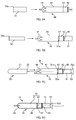
- Figs. 1 and 2 are cross-sectional views illustrating components of a tampon 10.
- Fig. 1 shows the tampon 10 in a state where an inner cylinder 50 is contracted and
- Fig. 2 shows the tampon 10 in a state where the inner cylinder 50 is extended.
- Fig. 3 is a diagram illustrating how a first inner cylinder 51 and a second inner cylinder 52 are connected and is an enlarged view of an area labeled "X" in Fig. 2 .
- Figs. 4A and 4B are external views of an outer cylinder 40.
- Fig. 4C is a diagram showing the outer cylinder 40 of Fig. 4A from its leading end side.
- Fig. 5 is an external view of the first inner cylinder 51.
- Fig. 1 shows the tampon 10 in a state where an inner cylinder 50 is contracted
- Fig. 2 shows the tampon 10 in a state where the inner cylinder 50 is extended.
- Fig. 3 is
- FIG. 6 is an external view of the second inner cylinder 52.
- a side that is inserted into a vagina will be referred to as a leading end side and an opposite side will be referred to as a rear end side.
- the tampon 10 of the present embodiment is a sanitary product having a tampon main body 20 and an applicator 30.
- the tampon main body 20 includes a cotton body 21 and a cord 22 sewn onto the cotton body 21.
- the cotton body 21 is an absorbent body that blocks a vaginal cavity and absorbs menstrual blood and the like.
- the cotton body 21 is formed by cutting a cotton strip 23 covered with non-woven fabric on both sides (see Fig. 8A ), pressing the cotton strip 23 and then heat forming the cotton strip 23 into a substantially bullet like shape.
- the cord 22 extends from a rear end side of the cotton body 21 and is held by a user when withdrawing the cotton body 21 from inside of the vaginal cavity to outside of the vaginal cavity. Also, as shown in Fig. 1 , the cord 22 extends through the applicator 30 and is somewhat pulled out from a rear end of the applicator 30. In the following description, a portion of the cord 22 that is exposing from the rear end of the applicator 30 is referred to as an exposing portion 22a. An end of the cord 22 at a free end side is referred to as a rear end and an end on a fixed end side (the cotton body 21 side) is referred to as a leading end of the cord 22.
- the applicator 30 is a cylindrical member and accommodates the tampon main body 20 in a state where the cord 22 is exposed from the rear end thereof.
- the applicator 30 is also an aid device for facilitating the guiding of the tampon main body 20 (specifically, the cotton body 21) into the vaginal cavity.
- the applicator 30 includes the outer cylinder 40 which is to be a part that accommodates the tampon main body 20 and the inner cylinder 50 which pushes out the tampon main body 20 that has been accommodated in the outer cylinder 40.
- the outer cylinder 40 is a cylindrical body made of a thermoplastic resin and has an appropriate flexibility.
- the outer cylinder 40 includes a major diameter part 41 provided at the leading end part and a minor diameter part 42 provided at the rear end part and that has an external diameter smaller than that of the major diameter part 41.
- the major diameter part 41 has an internal diameter that is slightly greater than the external diameter of the tampon main body 20.
- the tampon main body 20 is accommodated inside the major diameter part 41 of the outer cylinder 40. When using the tampon 10, the major diameter part 41 is inserted into the vaginal cavity with the tampon main body 20 being accommodated therein.
- the tampon main body 20 is accommodated in the major diameter part 41 in such a manner that its outer peripheral surface is in contact with an inner peripheral surface of the major diameter part 41.
- the minor diameter part 42 is a grip part held by a user when using the tampon 10. Note that the minor diameter part 42 is not necessarily provided on the outer cylinder 40.
- the outer cylinder 40 includes a leading end opening 43 and a plurality of petaloid parts 44 (in the present embodiment, six petaloid parts 44) surrounding the leading end opening 43.
- Each of the plurality of petaloid parts 44 is provided at the leading end part of the outer cylinder 40 and, at the time the tampon 10 is shipped, it is inwardly bent in an arc in the radial direction of the outer cylinder 40 as shown in Fig. 4A . Therefore, at the time the outer cylinder 40 is inserted into the vaginal cavity, the leading end part of the outer cylinder 40 is substantially hemispherical as shown in Figs.
- each of the plurality of petaloid parts 44 is open and the leading end opening 43 is in an open state.
- the outer cylinder 40 includes a rear end opening 45 and an annular rib 46 provided slightly towards the leading end side than the rear end opening 45. Further, an annular stepped part 47 is formed between the major diameter part 41 and the minor diameter part 42.
- the inner cylinder 50 is a cylindrical body inserted in the minor diameter part 42 of the outer cylinder 40.
- the inner cylinder 50 is situated at a position at the rear end side than the tampon main body 20 accommodated in the outer cylinder 40, travels along a central axis of the outer cylinder 40, and pushes the tampon main body 20 from the rear towards the leading end side opening 43.
- the tampon main body 20 pushes each of the plurality of petaloid parts 44 outwardly in the radial direction of the outer cylinder 40 (i.e., opens the leading end opening 43), and is pushed out of the outer cylinder 40.
- the inner cylinder 50 is movable in the outer cylinder 40 and has a function of pushing the tampon main body 20 out of the outer cylinder 40 through the leading end opening 43.
- the inner cylinder 50 of the present embodiment has a telescopic structure in order to provide a shorter overall length of the tampon 10 to make it compact.
- the length of the inner cylinder 50 becomes shorter than the length of the outer cylinder 40 and becomes a length that is convenient for carrying.
- the inner cylinder 50 extends as shown in Fig. 2 , the length of the inner cylinder 50 becomes a length that is sufficient to push the tampon main body 20 out of the outer cylinder 40.
- the inner cylinder 50 in order to achieve the telescopic structure of the inner cylinder 50, the inner cylinder 50 has a two-tier structure.
- the inner cylinder 50 of the present embodiment includes the first inner cylinder 51 and the second inner cylinder 52 that is slidably inserted into the first inner cylinder 51.
- the first inner cylinder 51 is a cylindrical body made of plastic.
- the first inner cylinder 51 has an external diameter that is slightly smaller than an internal diameter of the minor diameter part 42 of the outer cylinder 40.
- the first inner cylinder 51 is slidably inserted into the minor diameter part 42.
- an annular flange part 51a is formed on an outer peripheral surface of the leading end part of the first inner cylinder 51.
- the flange part 51a has an external diameter that is slightly smaller than the major diameter part 41 of the outer cylinder 40 and engages an inner wall of the stepped part 47, to thereby prevent the inner cylinder 50 from falling off from the rear end opening 45 of the outer cylinder 40.
- the inner cylinder 50 pushes the tampon main body 20 out of the outer cylinder 40, the inner cylinder 50 moves in such a manner that the outer peripheral surface of the flange part 51a comes into contact with the inner peripheral surface of the major diameter part 41. Further, as shown in Figs. 1 and 2 , at the rear end side on an inner peripheral surface of the first inner cylinder 51, an annular protrusion 51b protruding inwardly in the radial direction of the first inner cylinder 51 is provided.
- the second inner cylinder 52 is a cylindrical body made of thermoplastic resin.
- the second inner cylinder 52 has an external diameter that is slightly smaller than an internal diameter of the first inner cylinder 51.
- the second inner cylinder 52 is, when the inner cylinder 50 is in a contracted state, inserted in the first inner cylinder 51 as shown in Fig. 1 and, when the inner cylinder 50 is in an extended state, connected to the rear end part of the first inner cylinder 51 at the leading end part of the second inner cylinder 52 as shown in Fig. 2 .
- an arcuate flange part 52a and a protruded part 52b provided at a position nearer to the rear end side than the flange part 52a are formed on the outer peripheral surface of the leading end part of the second inner cylinder 52.
- a height of the protruded part 52b gradually lowers towards the rear end. Note that a space between the flange part 52a and the protruded part 52b of the second inner cylinder 52 is slightly greater than a thickness of the annular protrusion 51b of the first inner cylinder 51.
- the annular protrusion 51b of the first inner cylinder 51 will be at a position between the flange part 52a and the protruded part 52b of the second inner cylinder 52.
- the annular protrusion 51b engages the flange part 51a and the protruded part 52b, and thus the first inner cylinder 51 and the second inner cylinder 52 are connected.
- a flared part 52c is formed at the rear end part of the second inner cylinder 52.
- An external diameter of the flared part 52c is preferably at least greater than the internal diameter of the first inner cylinder 51 and greater than or equal to the internal diameter of the minor diameter part 42 of the outer cylinder 40.
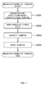
- a method of manufacturing the tampon 10 of the above-mentioned structure includes a step of manufacturing each component constituting the tampon 10 (hereinafter referred to as a component-manufacturing step S001), a step of manufacturing the tampon 10 by assembling each of the manufactured components into the tampon (hereinafter referred to as a main manufacturing step S002), a step of inspecting the manufactured tampon 10 (hereinafter referred to as an inspecting step S003) and a step of wrapping the tampon 10 (hereinafter referred to as a wrapping step S004).
- Fig. 7 is a flowchart showing a manufacturing flow of the tampon 10. Each of the above-mentioned steps will be described below.
- the tampon main body 20, the outer cylinder 40 and the inner cylinder 50 (specifically, the first inner cylinder 51 and the second inner cylinder 52) which constitute the tampon 10 are manufactured, respectively.
- the outer cylinder 40, the first inner cylinder 51 and the second inner cylinder 52 are respectively manufactured by injection molding. It is to be noted that, the outer cylinder 40 is manufactured with each of the plurality of petaloid parts 44 being in an open state (the outer cylinder 40 shown in Fig. 4B ). The second inner cylinder 52 is manufactured without the flared part 52c being formed (the second inner cylinder 52 shown in Fig. 6 ).
- the tampon main body 20 is manufactured in accordance with a procedure shown in Figs. 8A to 8C.
- Figs. 8A to 8C are explanatory diagrams showing the procedure of manufacturing the tampon main body 20.
- a cotton strip 23 covered with non-woven fiber on both surfaces is cut in a fletching shape.
- a cord 22 is sewn to the cut cotton strip 23.
- the cord 22 is continuously supplied and, after being sewn onto the cotton strip 23, the cord 22 is cut into a predetermined length (a length within a standard range) by a cutter (not shown).
- a predetermined length a length within a standard range
- the cotton strip 23 with the cord 22 sewn thereon is pressed into a cylindrical shape by a pressing machine 200. Thereafter, the cotton strip 23 is heat formed into a substantially bullet-like shape by a heat forming machine (not shown). With the procedure described above, the tampon main body 20 shown in Fig. 8C is manufactured.
- FIGs. 9A to 9D are transitional diagrams showing how the tampon 10 is manufactured.
- the main manufacturing step S002 starts with supplying each of the components manufactured in the component-manufacturing step S001 to an assembly line.
- each of the components is assembled into the tampon 10.
- the outer cylinder 40 formed by injection molding is supplied to the assembly line. Note that, as shown in Fig. 9A , the outer cylinder 40 at the time supplied to the assembly line is in a state where each of the plurality of petaloid parts 44 is open (i.e., the leading end opening 43 is in an open state).
- the first inner cylinder 51 formed by injection molding is inserted into the outer cylinder 40 through the leading end opening 43.
- the first inner cylinder 51 inserted into the outer cylinder 40 is in a state where its rear end part protrudes from the rear end opening 45 of the outer cylinder 40 and the flange part 51a engages with an inner wall surface of a stepped part 47 of the outer cylinder 40 (see Fig. 9B ).
- the second inner cylinder 52 formed by injection molding is inserted into the outer cylinder 40 through the leading end opening 43.
- the second inner cylinder 52 inserted into the outer cylinder 40 is in a state where its rear end part is protruded from the opening on a rear end side of the first inner cylinder 51 and the flange part 52a engages with an inner peripheral surface of the first inner cylinder 51 (see Fig. 9C ).
- the rear end part of the second inner cylinder 52 is heat formed to form a flared part 52c.
- the tampon main body 20 manufactured in accordance with the above-described procedure is supplied to the assembly line and the tampon main body 20 is inserted into the outer cylinder 40 through the leading end opening 43.
- the tampon main body 20 is inserted from a side where the cord 22 is provided. Thereby, the tampon main body 20 is accommodated in the outer cylinder 40 with a proper orientation.
- the tampon main body 20 is inserted into the outer cylinder 40, the cotton body 21 is accommodated in the major diameter part 41 of the outer cylinder 40 and the cord 22 somewhat extends out of the rear end of the applicator 30 (specifically, an opening on the rear end side of the second inner cylinder 52).
- the tampon main body 20 is accommodated in the applicator 30 and the exposing portion 22a of the cord 22 is exposed from the rear end of the applicator 30.
- a process of heat forming the leading end part of the outer cylinder 40 into a substantially hemispherical shape (hereinafter referred to as a leading end processing) is performed in which each of the plurality of petaloid parts 44 is bent in such a manner that it is inclined inwardly in a radial direction of the outer cylinder 40.
- a leading end processing a process of heat forming the leading end part of the outer cylinder 40 into a substantially hemispherical shape
- a step of inspecting a length of the cord 22 of the tampon main body 20 is performed on the tampon 10 manufactured in the main manufacturing step S002.
- This step is performed by an inspecting apparatus 100 described below and, in the present embodiment, performed on all the tampons 10. (I.e., a 100% inspection is performed) .
- the tampons 10 are screened in accordance with the inspection results at the inspecting apparatus 100.
- the length of the cord 22 is normal (specifically, the length within the standard range)
- the tampon 10 is transported to the wrapping step S004 at a later stage.
- the tampon 10 having the cord 22 whose length is not normal is removed and collected.
- an inspecting method performed in the inspecting step S003 corresponds to the method of inspecting the tampon 10 according to the present embodiment.
- the method of inspecting the tampon 10 according to the present embodiment includes a step of inspecting the length of the cord 22 provided on the tampon 10 (in detail, the cord 22 provided on the tampon main body 20 of the tampon 10). This step will be described in detail later.
- the tampon 10 is inserted into a wrapping film having a bag-shape to wrap the tampon 10 individually.
- the wrapped tampons 10 are packed in a box and thereafter shipped.
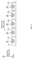
- Fig. 10 is a schematic diagram illustrating the inspecting apparatus 100 and is an upper view of the inspecting apparatus 100.
- a transport direction of the tampon 10 and an interacting direction that intersects with the transport direction are shown by arrows.
- the inspecting apparatus 100 of the present embodiment includes a transport mechanism 110 and a cord-length inspecting mechanism 120 shown in Fig. 10 , as well as a suction mechanism 130 (e.g., see Fig. 12B ).
- the transport mechanism 110 transports the tampon 10 manufactured in the main manufacturing step S002 in the transport direction that intersects with a longitudinal direction of the tampon 10.
- the transport direction in the present embodiment is a direction that is substantially perpendicular to the longitudinal direction of the tampon 10 and particularly a horizontal direction.
- the transport mechanism 110 of the present embodiment includes a transport belt that extends along the transport direction and transports the tampon 10 together with a holder 110a, with tampon 10 being held by the holder 110a.
- Fig. 11 is a side view of the transport mechanism 110.
- the holder 110a is a substantially rectangular parallelepiped member that is fixed to the transport mechanism 110 and, as shown in Fig. 11 , holds the tampon 10 by fitting the applicator 30 into a substantially hemicylindrical recess formed at a central part in the transport direction in the holder 110a.
- the tampon 10 held by the holder 110a takes a posture in which its longitudinal direction lies along the intersecting direction (a transversely-situated posture).
- the intersecting direction is a direction that intersects with the transport direction and, in the present embodiment, it is a direction that intersects with the transport direction in a horizontal plane.
- the transport mechanism 110 transports the tampon 10 in the transport direction while maintaining the posture of the tampon 10 in the above-mentioned posture.
- a side where the leading end of the tampon 10 is situated as seen from a rear end of the tampon 10 that is being transported is referred to as a one-end side and a side where the rear end of the tampon 10 is situated as seen from the leading end of the tampon 10 is referred to as an other-end side (see Fig. 10 ).
- the transport mechanism 110 sequentially transports the tampons 10 at a certain spacing in the transport direction (in the present embodiment, the spacing is approximately 50.8 mm) .
- the spacing is approximately 50.8 mm.
- each tampon 10 travels while taking the same position in the intersecting direction. That is to say, each tampon 10 travels to a downstream side in the transport direction in such a manner that positions of the leading ends of the tampons 10 are situated at the same position in the intersecting direction.
- a plurality of holders 110a are arranged in in a series along the transport direction and are transported in the transport direction with the positions of the holders 110a in the intersecting direction being the same.
- Each tampon 10 is held by the holder 110a in such a manner that a leading-end-side end surface of the annular rib 46 provided on the outer cylinder 40 is in contact with an other-end surface of the holder 110a that is at the other end in the intersecting direction (see Fig. 10 ).
- each tampon 10 is transported in the transport direction together with the holder 110a in such a manner that the leading end positions of the tampons 10 are the same among the tampons 10.
- the cord-length inspecting mechanism 120 performs an inspection of the length of the cord 22 on each tampon 10, while each tampon 10 is being transported. As shown in Fig. 10 , the cord-length inspecting mechanism 120 includes a sensor 121 and a casing 122.
- the sensor 121 is provided for the cord-length inspecting mechanism 120 to inspect the length of the cord 22 and is provided on the other-end side in the intersecting direction as seen from the tampon 10 that is being transported.
- the sensor 121 of the present embodiment is an optical sensor that irradiates light and detects the presence of the cord 22 on an optical path of the irradiate light when the irradiated light is interrupted.
- three sensors 121 are provided that are aligned along the intersecting direction.
- the three sensors 121 are situated in such a manner that their positions are substantially the same in the transport direction and are mutually different in the intersecting direction.
- the sensor 121 situated at the most one-end side in the intersecting direction (the sensor 121 situated at a position nearest to the tampon 10 that is being transported) is referred to as a one-end side sensor 121a
- the sensor 121 situated at the most other-end side (the sensor 121 situated at a position furthest from the tampon 10 that is being transported)
- the sensor 121 situated between the one-end side sensor 121a and the other-end side sensor 121c is referred to as a middle sensor 121b.
- the one-end side sensor 121a is situated at a position offset from a reference position by approximately 19 mm on the other end side in the intersecting direction.
- the reference position is a position which is taken as a reference by the cord-length inspecting mechanism 120 when inspecting the cord 22 of each tampon 10.
- the reference position in the present embodiment corresponds to a position of the other-end-surface of the holder 110a in the intersecting direction.
- the reference position corresponds to the position of the leading-end-side end-surface of the annular rib 46 of the outer cylinder 40 of each tampon 10. It is to be noted that the reference position is not limited to the above-mentioned position and can be any another position (e.g., a position of the rear end of the applicator 30).
- the one-end side sensor 121a detects the presence or absence of the cord 22 at a position that is slightly to the other-end side in the intersecting direction than the rear end of the applicator 30, when the rear end of the applicator 30 of the tampon 10 comes to the same position as a the one-end side sensor 121a in the transport direction.
- the one-end side sensor 121a is a sensor 121 that detects whether the cord 22 of the tampon 10 is exposed from the rear end of the applicator 30 (i.e., presence or absence of the exposing part 22a) and is provided for inspecting whether the cotton body 21 to which the cord 22 is sewn (i.e., the tampon main body 20) is accommodated in the applicator 30 and whether the cord 22 is sewn to the cotton body 21 in the applicator 30. Note that it is not necessary to provide the one-end side sensor 121a.
- the middle sensor 121b is a sensor 121 that is situated on the other-end side in the intersecting direction by approximately 45 mm from the one-end side sensor 121a and corresponds to a first optical sensor.
- the other-end side sensor 121c is a sensor 121 that is situated on the other-end side in the intersecting direction by approximately 70 mm from the one-end side sensor 121a and corresponds to a second optical sensor.
- the middle sensor 121b and the other-end side sensor 121c are the sensors 121 provided in the cord-length inspecting mechanism 120 for inspecting whether the cord 22 of each tampon 10 has a normal length.
- the cord-length inspecting mechanism 120 determines that the length of the cord 22 is normal.
- each of the one-end side sensor 121a, the middle sensor 121b and the other-end side sensor 121c is provided one each at two places in the transport direction.
- Each of the two one-end side sensors 121a is situated at the same position in the intersecting direction.
- each of the two middle sensors 121b and each of the two other-end side sensors 121c are situated at the same positions in the intersecting direction, respectively.
- two sets of combination of the one-end side sensor 121a, the middle sensor 121b and the other-end side sensor 121c are provided.
- the inspection accuracy of the cord-length inspecting mechanism 120 is improved.
- the number of sets of combination of the one-end side sensor 121a, the middle sensor 121b and the other-end side sensor 121c is not limited to two sets.
- a single set of such combination or more than two sets of such combination may be provided.
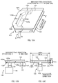
- the casing 122 is a frame body provided on the other-end side in the intersecting direction as seen from the tampon 10 being transported, and includes, as shown in Figs. 12A to 12C , a lower wall 123, an upper wall 124 and a side wall 125.
- Figs. 12A to 12C are diagrams schematically illustrating the casing 122.
- Fig. 12A is a perspective view of the casing 122.
- Fig. 12B is a front view of the casing 122 and is a diagram illustrating the casing 122 seen from a direction of an arrow A in Fig. 12A.
- Fig. 12C is a side view of the casing 122 and is a diagram illustrating the casing 122 seen from a direction of an arrow B in Fig. 12A .
- the lower wall 123 and the upper wall 124 are an example of a pair of walls and are arranged in such a manner that they opposes each other in the vertical direction.
- Each of the lower wall 123 and the upper wall 124 is a flat wall placed substantially horizontally and extends along the transport direction. Further, as shown in Fig. 12A , each of the lower wall 123 and the upper wall 124 has a substantially homebase shape when viewed in the vertical direction.
- the shape of each of the lower wall 123 and the upper wall 124 is not limited to the shape of the present embodiment and may be, for example, substantially rectangular, substantially triangular or substantially semicircular when viewed from above.
- a gap 126 is formed between the lower wall 123 and the upper wall 124.
- the width (a size along the vertical direction) of the gap 126 is approximately 5 mm and the depth (a size along the transport direction) is approximately 120 mm (see Fig. 12C ).
- both end parts in the transport direction of the upper wall 124 is bent upwards and away from the lower wall 123. That is, as shown in Fig. 12C , the upper wall 124 is substantially arcuate when viewed in the intersecting direction and a spacing of the gap 126 is somewhat greater at the both end parts in the transport direction than the spacing at the central part in the transport direction.
- the side wall 125 is an example of another wall and, as shown in Figs. 12A and 12B , it is sandwiched between the lower wall 123 and the upper wall 124 and has a substantially U shape when viewed from above.
- the side wall 125 includes a central part 125a provided at the central part in the transport direction, angled parts 125b provided adjacent to both end parts of the central part 125a, respectively, each of the angled parts 125b being angled in such a manner that it reaches toward the the one-end side in the intersecting direction as it gets away from the central part 125a, and end parts 125c that are provided at both end parts in the transport direction of the side wall 125, respectively, and that lie along the intersecting direction.
- a one end in the intersecting direction of each of the end parts 125c is situated somewhat on the other-end side in the intersecting direction than one end in the intersecting direction of each of the lower wall 123 and the upper wall 124. Note that the position of the one end in the intersecting direction of the end part 125c is situated on the other-end side in the intersecting direction by approximately 89 mm from the reference position (see Fig. 10 ).
- the side wall 125 closes the other-end part in the intersecting direction of the gap 126.
- the one end in the intersecting direction of the gap 126 is an open end. That is to say, the casing 122 includes an opening 127 that is formed in such a manner that the gap 126 is open at the one-end side in the intersecting direction. Also, the side wall 125 closes the gap 126 on the other side of the opening 127 in the intersecting direction.
- the casing 122 has a hole 123a that penetrates through the lower wall 123 in a vertical direction.
- This hole 123a is a circular hole that is formed in the central part in the transport direction of the lower wall 123 and that is situated somewhat to the one-end side than the other end in the intersecting direction of the lower wall 123 (specifically, slightly to the one-end side than the one-end surface in the intersecting direction of the central part 125a of the side wall 125.
- a duct 131 which is to be described later, is connected at a position where the hole 123a is formed in the lower wall 123. Note that the position at which the hole 123a is formed is not limited to the position described above and the hole 123a should be formed in either of the lower wall 123, the upper wall 124 and the side wall 125.
- the casing 122 of the above-described structure is arranged in such a manner that applicator 30 of the tampon 10 travels in the vicinity thereof.
- the transport mechanism 110 transports each of the tampons 10 in the transport direction, with the tampon 10 being situated on the opening 127 side in the intersecting direction, in such a manner that the rear end of the applicator 30 opposes the opening 127 (see Fig. 10 ).
- the casing 122 is arranged in such a manner that, when the tampon 10 is transported in the transport direction, the exposing portion 22a of the cord 22 provided on the tampon 10 passes through the gap 126 formed between the lower wall 123 and the upper wall 124. That is to say, the transport mechanism 110 of the present embodiment transports the tampon 10 in such a manner that the exposing portion 22a passes through the gap 126 along the transport direction.
- the above-mentioned middle sensor 121b and the other-end side sensor 121c are accommodated in the casing 122.
- the middle sensor 121b and the other-end side sensor 121c are mounted on an inner wall surface of one of the lower wall 123 and the upper wall 124. That is to say, the middle sensor 121b and the other-end side sensor 121c are the sensors 121 for inspecting, in the gap 126, the length of the cord 22 that passes through the gap 126.
- the position at which the length of the cord 22 is detected by each of the middle sensor 121b and the other-end side sensor 121c is situated inside the gap 126 and, in the present embodiment, situated at the central part in the transport direction of the gap 126.
- the position at which the presence and absence of the exposing portion 22a of the cord 22 is detected by the other-end side sensor 121a is situated outside the gap 126 (on the one-end side than the opening 127 in the intersecting direction).
- each of the sensors 121 is situated on the one-end side in the intersecting direction of the position at which the hole 123a is formed (see Fig. 10 ).
- the hole 123a is situated on the side wall 125 side (the other end side) in the intersecting direction of each of the sensors 121 (specifically, the other-end side sensor 121c).
- a suction mechanism 130 sucks air inside the casing 122 through the hole 123a (specifically, air inside the gap 126).
- the suction mechanism 130 includes a duct 131, and suction pump 132 as a suction source (see Fig. 12C ).
- the duct 131 is an accordion-type duct provided between the suction pump 132 and the hole 123a, and forms a wind path when the suction pump 132 sucks the air inside the casing 122.
- the suction pump 132 sucks the air at a predetermined suction pressure (in the present embodiment, approximately 0.7kPa).
- an internal diameter of the duct 131 in the present embodiment, approximately 34 mm
- a diameter of the hole 123a in the present embodiment, approximately 25 mm).
- a suction operation by the suction pump 132 is performed while the cord 22 (specifically, the exposing portion 22a of the cord 22) of each of the tampons 10 is passing through the gap 126.
- the cord 22 is extended straight along the longitudinal direction of the tampon 10, while passing through the central part in the transport direction of the gap 126.
- the suction pump 132 is continuously operating.
- the suction pump 132 may be operated (perform a suction operation) only during a period when the exposing portion 22a of the cord 22 is passing through the gap 126.
- the position at which the suction mechanism 130 is situated may be any position as long as the suction operation is performed in a manner described above.
- the cord-length inspecting mechanism 120 having the above-mentioned sensors 121 and the casing 122 inspects the length of the cord 22 of each of the tampons 10 with the above-described three sensors 121 while the suction mechanism 130 is sucking air.
- the cord-length inspecting mechanism 120 inspects the length of the cord 22 with the above-mentioned three sensors 121 when the exposing portion 22a of the cord 22 passes through the central part in the transport direction of the gap 126 (i.e., while the cord 22 is being extended along the longitudinal direction of the tampon 10). The inspection operation of the cord-length inspecting mechanism 120 will be described in detail later in the next section.
- the inspecting apparatus 100 of the present embodiment further includes a pull-out mechanism 140 and a contacting member 150.
- the pull-out mechanism 140 is a mechanism that forcedly pulls out the cord 22 (specifically, a portion that is supposed to be the exposing portion 22a) from the rear end of the applicator 30 when a portion of the cord 22 of the tampon 10 that is supposed to be the exposing portion 22a is buried inside the applicator 30 and is not properly exposed from the rear end of the applicator 30 due to twist and slack.
- the pull-out mechanism 140 is provided upstream of the cord-length inspecting mechanism 120 in the transport direction.
- the pull-out mechanism 140 pulls out the cord 22 by performing a suction operation that sucks air from the rear end side of the applicator 30 of each of the tampons 10 (hereinafter referred to as a pre-suction operation).
- a pre-suction operation a suction operation that sucks air from the rear end side of the applicator 30 of each of the tampons 10
- the pull-out mechanism 140 includes a suction pipe 141 shown in Fig. 10 and a suction source.
- the suction pipe 141 is, in the transport direction, situated upstream of the cord-length inspecting mechanism 120.
- the air inside the suction pipe 141 is sucked by the suction source of the pull-out mechanism 140.
- the suction pipe 141 extends along the intersecting direction.
- a connection pipe 142 is connected that has a diameter different from that of the suction pipe 141.
- the suction pipe 141 is connected to a suction inlet (not shown) of the above-mentioned suction source via the connection pipe 142.
- a pair of cut-away portions 141a is formed that opposes each other in the transport direction.
- Fig. 13 is a diagram showing a leading end side opening of the suction pipe 141.
- Each of the cut-away portions 141a has a height of approximately 20 mm in the vertical direction and a width of approximately 15 mm in the intersecting direction (see Figs. 10 and 13 ). Note that the height of each of the cut-away portions 141a is greater than the external diameter of the rear end part of the applicator 30 (specifically, external diameters of the first inner cylinder 51 and the second inner cylinder 52).
- the tampon 10 travels in the transport direction in such a manner that the rear end of the applicator 30 passes both of the pair of cut-away portions 141a.
- the transport mechanism 110 transports the tampon 10 in such a manner that the rear end of the applicator 30 passes through both of the pair of cut-away portions 141a (i.e., in such a manner that the rear end part of the applicator 30 passes inside the leading end part of the suction pipe 141) .
- the positional relationship in the intersecting direction between the transport path of the tampon 10 and the suction pipe 141 is, as shown in Fig. 10 , such that the rear end part of the applicator 30 of the tampon 10 and the leading end part of the suction pipe 141 overlap when the tampon 10 comes to a position, in the transport direction, where the suction pipe 141 is situated.
- the rear end part of the applicator 30 is capable of entering inside the leading end part of the suction pipe 141 through the cut-away portion 141a on the upstream side in the transport direction and leave from the leading end part through the cut-away portion 141a on the downstream side in the transport direction.
- the pull-out mechanism 140 of the above-described structure sucks the air inside the suction pipe 141 by the pre-suction operation during the transport of the tampon 10 while the rear end of the applicator 30 is situated between the pair of cut-away portions 141a in the transport direction (i.e., when the rear end part of the applicator 30 is situated inside the leading end part of the suction pipe 141).
- the cord 22 (specifically, the portion that is supposed to be the exposing portion 22a) will be pulled out.
- the cord 22 can be pulled out efficiently.
- the pull-out mechanism 140 of the present embodiment uses a suction pump 132 of the suction mechanism 130 as the suction source.
- the suction mechanism 130 and the pull-out mechanism 140 share the suction source.
- a suction force needs to be greater than the suction force for extending the cord 22 along the longitudinal direction of the tampon 10 with the suction operation.
- the leading end side opening of the suction pipe 141 i.e., an air inlet during the pre-suction operation
- the opening 127 of the casing 122 i.e., an air inlet during the suction operation
- a suction force required for pulling out the cord 22 in the pre-suction operation is appropriately ensured.
- suction source is not limited to a structure in which it is shared between the suction mechanism 130 and the pull-out mechanism 140, and each of the suction mechanism 130 and the pull-out mechanism 140 may include an individual suction source.
- the contacting member 150 is a rod provided upstream of the pull-out mechanism 140 in the transport direction. As shown in Fig. 14 , when the contacting member 150 is viewed from the upstream side in the transport direction, the contacting member 150 is bent in an L-shape and has an intersecting part 150a extending in the intersecting direction and a vertical part 150b extending in the vertical direction. Fig. 14 is a diagram showing the contacting member 150 in which the contacting member 150 is viewed from the upstream side in the transport direction.
- the contacting member 150 is supported by a substantially rectangular bracket 151 in such a manner that the intersecting part 150a of the contacting member 150 is fixed to the bracket 151. Further, the contacting member 150 is arranged in such a manner that the intersecting part 150a and the vertical part 150b are in contact with the cord 22 (specifically, the exposing portion 22a of the cord 22) of the tampon 10 that is being transported. Note that the positional relationship between the tampon 10 that is being transported and the contacting member 150 is as shown in Figs. 10 and 14 .
- the contacting member 150 comes into contact with the exposing portion 22a of the cord 22 of the tampon 10 while the tampon 10 is being transported.
- the exposing portion 22a will be caught by the contacting member 150. That is to say, the tampon 10 is transported in the transport direction in such a manner that the exposing portion 22a comes into contact with the contacting member 150 and is caught by the contacting member 150.
- the contacting member 150 prevents the exposing portion 22a from being sucked towards the suction pipe 141 by catching the exposing portion 22a of the cord 22 with the contacting member 150.
- the contacting member 150 comes into contact with an exposing portion 22a of a cord 22 of another one of the tampons 10 that is upstream of and adjacent to the one of the tampons 10 in the transport direction.
- the exposing portion 22a of the cord 22 of the other one of the tampons 10 is prevented from being sucked towards the suction pipe 141.
- the cord 22 of the tampon 10 that is under the pre-suction operation and the cord 22 of the tampon 10 that is downstream of and adjacent to such tampon 10 can be prevented from being tangled to each other.
- the inspecting step by the inspecting apparatus 100 starts with supplying each of the tampons 10 manufactured in a main manufacturing step S002 to the inspecting apparatus 100.
- each of the tampons 10 is set on the holder 110a by a setting mechanism (not shown).
- each of the tampons 10 is set with a posture in which its longitudinal direction is lying along the intersecting direction (a transversely-situated posture).
- the tampon 10 that is set on the holder 110a is transported in the transport direction by the transport mechanism 110 while maintaining the above-mentioned posture (see Fig. 10 ). Note that the tampon 10 is transported with a portion of the cord 22 being somewhat exposed from the rear end of the applicator 30.
- the transport mechanism 110 sequentially transports each of the tampons 10 in such a manner that each of the tampons 10 is arranged at a constant interval along the transport direction. Note that each of the tampons 10 arranged in the transport direction is transported in such a manner that the leading end positions of the tampons 10 are aligned with each other.
- the casing 122, the suction pipe 141 and the contacting member 150 are each situated on the other-end side in the intersecting direction. That is, the transport mechanism 110 transports each of the tampons 10 in such a manner that each of the tampons 10 is situated on the opening 127 side of the casing 122 in the intersecting direction, with the longitudinal direction of each of the tampons 10 being lying along the intersecting direction.
- the transport mechanism 110 transports the tampon 10 to the downstream side in the transport direction, the tampon 10 passes by a position at which the exposing portion 22a of the cord 22 comes into contact with the contacting member 150, and then arrives at a position at which the rear end of the applicator 30 reaches the leading end part of the suction pipe 141. Thereafter, the transport mechanism 110 transports the tampon 10 in such a manner that the rear end of the applicator 30 passes through both of the pair of cut-away portions 141a formed at the leading end part of the suction pipe 141.
- the pull-out mechanism 140 performs an operation of sucking air inside the suction pipe 141 (i.e., pre-suction operation).
- the cord 22 (specifically, a portion of the cord 22 that is supposed to be the exposing portion 22a) will be pulled out from the rear end of the applicator 30.
- the tampon 10 that is upstream of and adjacent to such tampon 10 in the transport direction is in a state where the exposing portion 22a of the cord 22 is in contact with the contacting member 150 and is caught by the contacting member 150.
- the cords 22 (specifically, the exposing portions 22a) are prevented from tangling with each other between the tampon 10 that is under pre-suction operation and the tampon 10 that is upstream of and adjacent to such tampon 10 in the transport direction.
- the tampon 10 is further transported to the downstream side in the transport direction and the rear end of the applicator 30 of such tampon 10 passes through the cut-away portion 141a on the downstream side in the transport direction and leaves the leading end part of the suction pipe 141.
- the exposing portion 22a of the cord 22 is, from the one end of the exposing portion 22a (an end situated at the rear end of the applicator 30) to the other end thereof (the rear end of the cord 22), rubbed against an edge of the cut-away portion 141a on the downstream side in the transport direction.
- the twist will be eliminated.
- the transport mechanism 110 transports the tampon 10 further to the downstream side in the transport direction. Then, when the tampon 10 arrives at a position in the transport direction where the cord-length inspecting mechanism 120 is provided, the cord-length inspecting mechanism 120 performs an operation of inspecting the length of the cord 22 of the tampon 10 (hereinafter referred to as the inspecting operation).
- the inspecting operation an operation of inspecting the length of the cord 22 of the tampon 10
- the tampon 10 moves to the downstream side in the transport direction in such a manner that the exposing portion 22a of the cord 22 enters the gap 126 formed between the lower wall 123 and the upper wall 124. It is to be noted that because both ends in the transport direction of the gap 126 are open ends, the exposing portion 22a will enter into the gap 126 from the upstream side end in the transport direction of the gap 126. Further, as has been described above, the spacing of the gap 126 is somewhat greater than the spacing at the central part in the transport direction at both end sides in the transport direction. Therefore, the exposing portion 22a can easily enter into the gap 126. Also, when the exposing portion 22a enters inside the gap 126, the rear end of the cord 22 is rubbed against one-end surface in the intersecting direction of the end part 125c of the side wall 125 (see Fig. 10 ).
- the tampon 10 moves to the downstream side in the transport direction in such a manner that the exposing portion 22a passes through the gap 126. That is, the transport mechanism 110 transports the tampon 10 in such a manner that the exposing portion 22a passes through the gap 126.
- the rear end of the applicator 30 is situated outside (on the one-end side in the intersecting direction) of the opening 127 of the casing 122.
- the positional relationship between the tampon 10 that is being transported and the casing 122 is such a relationship that the leading-end-side end surface of the annular rib 46 of the outer cylinder 40 of the tampon 10 (i.e., the above-described reference position) is situated on the one-end side in the intersecting direction by a predetermined distance (in the present embodiment, approximately 44 mm) from the one ends in the intersecting direction of the lower wall 123 and the upper wall 124.
- the tampon 10 comes to a position at which the length of the cord 22 of the tampon 10 is inspected by the sensors 121.
- the cord-length inspecting mechanism 120 inspects the length of the cord 22 based on signals outputted by the sensors 121, respectively, in accordance with the detection result.
- the suction pump 132 provided in the suction mechanism 130 is continuously in operation. Therefore, the suction mechanism 130 continuously sucks the air inside the casing 122 even when the exposing portion 22a of the cord 22 is traveling in the gap 126.
- the suction mechanism 130 sucks the air inside the casing 122 via the hole 123a formed in the lower wall 123 of the casing 122.
- the hole 123a is formed at the central part in the transport direction of the lower wall 123.
- the hole 123a is situated on the other-end side in the intersecting direction of the lower wall 123 (specifically, on the other-end side in the intersecting direction of the other-end side sensor 121c in the intersecting direction).
- FIG. 15 is a diagram showing an inside of the casing 122 during the inspecting operation of the cord-length inspecting mechanism 120. Further, near the central part in the transport direction of the gap 126, the above-mentioned airflow is regulated to flow substantially parallel to the intersecting direction.
- the hole 123a which is an air outlet of the above-mentioned airflow is situated at a position corresponding to the central part in the transport direction of the gap 126 and the suction pressure of the suction pump 132 is regulated in such a manner that the suction mechanism 130 sucks the air inside the casing 122 at an appropriate suction force.
- the sensors 121 are provided within a range in which the airflow is regulated in a manner described above in the transport direction. Therefore, when the exposing portion 22a of the cord 22 of the tampon 10 passes through the central part in the transport direction of the gap 126 (i.e., at a position where the length of the cord 22 is inspected by the sensors 121 in the transport direction), the cord 22 is extended substantially straight by being blown by the regulated airflow. That is to say, when the cord-length inspecting mechanism 120 inspects the length of the cord 22, the cord 22 is extended along the longitudinal direction of the tampon 10 by the suction operation.
- the suction mechanism 130 sucks air at the other-end side in the intersecting direction of the tampon 10 that is being transported (on the other-end side in the intersecting direction of the rear end of the cord 22 of the tampon 10) to thereby extend the cord 22 of the tampon 10 along the longitudinal direction of the tampon 10.
- the suction mechanism 130 sucks air inside the casing 122 while the exposing portion 22a of the cord 22 is passing through the gap 126 to thereby extend the cord 22 along the longitudinal direction of the tampon 10.
- the cord-length inspecting mechanism 120 performs an inspecting operation of inspecting the length of the cord 22.
- the length of the cord 22 of the tampon 10 will be inspected in a state where the cord 22 is extended straight along the longitudinal direction of the tampon 10.
- the cord-length inspecting mechanism 120 inspects the length of the cord 22 using the above-described three sensors 121 (that is, one-end side sensor 121a, middle sensor 121b and other end side sensor 121c). That is to say, the cord-length inspecting mechanism 120 inspects the length of the cord 22 based on output signals from the respective three sensors 121, when the tampon 10 passes by the positions at which the three sensors 121 are provided in the transport direction (i.e., the positions at which the length of the cord 22 is inspected by the sensors 121).
- the cord-length inspecting mechanism 120 inspects the length of the cord 22 in the inspecting operation.
- the signal outputted when the exposing portion 22a of the cord 22 has passed the position at which each of the sensors 121 is provided is referred to as a cord presence signal and the signal outputted when the exposing portion 22a has not passed the above-mentioned position is referred to as a cord absence signal.
- the cord-length inspecting mechanism 120 determines that the length of the cord 22 is normal.
- all of the three sensors 121 output the cord absence signals and the cord-length inspecting mechanism 120 determines that the length of the cord 22 is not normal.
- two sets of three sensors 121 are provided.
- the cord-length inspecting mechanism 120 performs the inspection of the length of the cord 22 twice.
- the two sets of three sensors 121 are both provided within a range that the above-mentioned airflow is regulated in the transport direction. Therefore, the two inspections performed by the cord-length inspecting mechanism 120 are both performed in a state where the cord 22 is extended along the longitudinal direction of the tampon 10.
- the transport mechanism 110 transports the tampon 10 to the downstream side in the transport direction
- the exposing portion 22a of the cord 22 of the tampon 10 leaves the gap 126 from the downstream side end in the transport direction of the gap 126.
- the inspecting operation by the cord-length inspecting mechanism 120 is terminated (i.e., the inspecting operation by the inspecting apparatus 100 is completed).
- the tampon 10 that has been determined that the length of the cord 22 is normal in the above-mentioned inspection operation (specifically, the tampon 10 that has been determined that the length of the cord 22 is normal at each of the two inspection) is continuously transported to the next wrapping step.
- the tampon 10 that has been determined in the above-mentioned inspecting operation that the length of the cord 22 is not normal is collected as a defective product by a collecting mechanism (not shown) .
- the suction mechanism 130 performs a suction operation and extends the cord 22 of the tampon 10 along the longitudinal direction of the tampon 10, and the cord-length inspecting mechanism 120 inspects the length of the cord 22 during the above-mentioned suction operation.
- the inspecting method of the tampon 10 of the present embodiment includes the step of extending the cord 22 along the longitudinal direction of the tampon by sucking air by the suction mechanism 130 (specifically, the above-mentioned suction operation) and the step of inspecting the length of the cord 22 while the suction mechanism 130 is sucking the air (specifically, the inspection operation by the inspecting mechanism 120).
- the length of the cord 22 can be accurately inspected.
- the length of the cord 22 can be inspected while keeping the cord 22 in a state where it is extended along the longitudinal direction of the tampon 10 (or simply stating, in a state where it is extended straight). As a result, the length of the cord 22 can be inspected accurately.
- the cord-length inspecting mechanism 120 of the present embodiment has the casing 122 that includes the lower wall 123 and the upper wall 124 (corresponding to the pair of walls) that lie along the transport direction. While the exposing portion 22a of the cord 22 is passing through the gap 126 between the lower wall 123 and the upper wall 124, the suction mechanism 130 sucks the air inside the casing 122 at the other-end side in the intersecting direction than the rear end of the cord 22. Thus, the cord 22 is extended along the longitudinal direction of the tampon 10. Meanwhile, the cord-length inspecting mechanism 120 inspects the length of the cord 22 by the sensors 121.
- the above-mentioned structure is a simple structure for inspecting the length of the cord 22 while extending the cord 22 straight. That is, in the present embodiment, the length of the cord 22 can be inspected accurately with a simple structure.
- another structure for inspecting the length of the cord 22 while extending the cord 22 straight may include a suction apparatus at the rear end side of the tampon 10 that is being transported and the suction apparatus may be moved in the transport direction together with the tampon 10.
- the cord 22 can be extended straight along the longitudinal direction of the tampon 10. Therefore, by inspecting the length of the cord 22 while the tampon 10 that is being transported, the length of the cord 22 can be inspected while keeping the cord 22 straight.
- the length of the cord 22 can be inspected while keeping the cord 22 straight using a stationary suction mechanism 130.
- the lower wall 123 has the hole 123a that is formed at the central part in the transport direction thereof and the suction mechanism 130 sucks the air inside the casing 122 through the hole 123a. Further, the hole 123a is situated at the other-end side in the intersecting direction than the sensors 121 (specifically, the other end side sensor 121c). With the structure described above, the inspection of the length of the cord 22 can be performed properly on each of the tampons 10 that is sequentially sent to the cord-length inspecting mechanism 120.
- the suction operation when the suction operation is performed by the suction mechanism 130, the airflow that is regulated to flow along the intersecting direction is generated at the central part in the transport direction of the gap 126 between the lower wall 123 and the upper wall 124.
- the cord 22 is extended straight when the exposing portion 22a of the cord 22 passes through the central part in the transport direction of the gap 126.
- a position at which the length of the cord 22 is inspected by the middle sensor 121b (which corresponds to the first optical sensor 121) and the other end side sensor 121c (which corresponds to the second optical sensor) is situated within a range that the airflow is regulated (i.e., the central part in the transport direction of the gap 126). Then, when the exposing portion 22a of the cord 22 of the tampon 10 passes through the central part in the transport direction of the gap 126, the cord-length inspecting mechanism 120 inspects the length of the cord 22 by the middle sensor 121b and the other end side sensor 121c. As a result, it is positively ensured that the length of the cord 22 is inspected while the cord 22 is extended straight.
- the three sensors 121 provided in the cord-length inspecting mechanism 120 i.e., the one-end side sensor 121a, the middle sensor 121b and the other end side sensor 121c
- the three sensors 121 provided in the cord-length inspecting mechanism 120 are situated at mutually different positions in the intersecting direction.
- the rear end of the cord 22 passes between the middle sensor 121b and the other end side sensor 121c in the intersecting direction.
- it is possible to properly inspect whether the length of the cord 22 is normal specifically, a length within a standard range).
- the pull-out mechanism 140 is provided upstream of the cord-length inspecting mechanism 120 in the transport direction.
- Each of the tampons 10 is subject to the pre-suction operation by the pull-out mechanism 140 before being subject to the suction operation by the suction mechanism 130 (before the cord 22 is extended along the longitudinal direction of the tampon 10). Then, with such pre-suction operation, the cord 22 that has not been properly exposed from the rear end of the applicator 30 (specifically, the portion that is supposed to be the exposing portion 22a) is pulled out from the rear end.
- the pair of cut-away portions 141a are formed at the leading end part of the suction pipe 141 of the pull-out mechanism 140.
- the transport mechanism 110 transports the tampon 10 in such a manner that the rear end part of the applicator 30 enters inside the leading end part of the suction pipe 141 through the cut-away portions 141a. Then, the pre-suction operation is performed when the rear end part of the applicator 30 is situated inside the leading end part of the suction pipe 141. Accordingly, the cord 22 that is not properly exposed from the rear end of the applicator 30 can be pulled out efficiently.
- the inspecting apparatus 100 and inspecting method for inspecting the tampon 10 of the present invention have been described with reference to the above embodiment.
- the above-described embodiment is provided for the purpose of facilitating the understanding of the present invention only and does not give any limitation to the present invention.
- any modifications and improvements to the present invention can be made without departing from the spirit of the invention and the present invention includes its equivalents.
- the above-mentioned setting values, sizes, and configurations, etc. are merely examples to produce the effect of the present invention and should not be understood as any limitation to the present invention.
- the above-described embodiment is directed to the tampon 10 having the inner cylinder 50 of a two-tier telescopic type.
- the present invention is not limited to such a structure.
- the tampon 10 may be of a type that includes the inner cylinder 50 with a fixed length (not telescopic).
- each of the tampons 10 is transported by the transport mechanism 110 while maintaining the transversely-placed posture.
- the present invention is not limited to such posture and each of the tampons 10 may be transported in the transport direction while maintaining a posture in which its longitudinal direction lies along the vertical direction (longitudinally-placed posture). That is to say, in Fig. 10 , the intersecting direction may correspond to the vertical direction. Even in such a case, the length of the cord 22 can be accurately inspected by performing the suction operation by the suction mechanism 130 on each of the tampons 10 while transporting each of the tampons 10 and inspecting the length of the cord 22 of each of the tampons 10 during such suction operation.
Landscapes
- Health & Medical Sciences (AREA)
- Epidemiology (AREA)
- Engineering & Computer Science (AREA)
- Biomedical Technology (AREA)
- Heart & Thoracic Surgery (AREA)
- Vascular Medicine (AREA)
- Life Sciences & Earth Sciences (AREA)
- Animal Behavior & Ethology (AREA)
- General Health & Medical Sciences (AREA)
- Public Health (AREA)
- Veterinary Medicine (AREA)
- Absorbent Articles And Supports Therefor (AREA)
Abstract
Description
- The present invention relates to an apparatus and method for inspecting a tampon. More particularly, the present invention relates to an apparatus and method for performing, on a tampon having a tampon main body that has a cord and an applicator that is cylindrical and that accommodates the tampon main body in such a manner that the cord is exposed from a rear end, an inspection of a length of the cord.
- Tampons are widely known as a sanitary product. Some tampons have a tampon main body that has a cord and an applicator that is cylindrical and that accommodates the tampon main body in such a manner that the cord is exposed from a rear end. The cord is provided for pulling a tampon main body, which has been inserted in a vagina, out of the vagina.
- The cord should be provided in a state where it has a normal length. Therefore, an inspection of a length of a cord may be performed on a tampon having the above structure (for example, Patent Literature 1).
- Patent Literature 1:
JP-A-2000-42031 - It is obvious that a length of a cord needs to be inspected accurately. However, for example, if the cord swings or is slack due to floppiness, it will be difficult to inspect the length of the cord accurately.
- The present invention has been made in view of such a disadvantage and the object of the present invention is to accurately perform, on a tampon having a tampon main body that has a cord and an applicator that is cylindrical and that accommodates the tampon main body in such a manner that the cord is exposed from a rear end, an inspection of a length of the cord.
- In order to achieve the above-mentioned object, the main aspect of the present invention is:
- an inspecting apparatus for inspecting a tampon, the tampon including a tampon main body that has a cord and an applicator that is cylindrical and that accommodates the tampon main body in such a manner that the cord is exposed from a rear end thereof, the inspecting apparatus comprising:
- a suction mechanism that extends the cord along a longitudinal direction of the tampon by sucking air; and
- a cord-length inspecting mechanism that inspects a length of the cord while the suction mechanism is sucking the air.
- Other features of the present invention will become apparent from descriptions of this specification and of accompanying drawings.
- According to an aspect of the invention, it is possible to accurately perform, on a tampon having a tampon main body that has a cord and an applicator that is cylindrical and that accommodates the tampon main body in such a manner that the cord is exposed from a rear end, an inspection of a length of the cord.
-
-
Fig. 1 is a cross-sectional view of elements of a tampon 10 (in a first state). -
Fig. 2 is a cross-sectional view of elements of a tampon 10 (in a second state). -
Fig. 3 is a diagram illustrating how a firstinner cylinder 51 and a secondinner cylinder 52 are connected. -
Fig. 4A and Fig. 4B are external views of anouter cylinder 40. -
Fig. 4C is a diagram showing theouter cylinder 40 ofFig. 4A from the leading end side. -
Fig. 5 is an external view of the firstinner cylinder 51. -
Fig. 6 is an external view of the secondinner cylinder 52. -
Fig. 7 is a flowchart showing a manufacturing flow of thetampon 10. -
Figs. 8A to 8C are explanatory diagrams showing a manufacturing procedure of the tamponmain body 20. -
Figs. 9A to 9D are transition diagram showing how thetampon 10 is manufactured. -
Fig. 10 is a schematic diagram illustrating aninspecting apparatus 100. -
Fig. 11 is a side view of atransport mechanism 110. -
Figs. 12A to 12C are schematic diagram of acasing 122. -
Fig. 13 is a diagram showing a leading end opening of asuction pipe 141. -
Fig. 14 is a diagram showing a contactingmember 150. -
Fig. 15 is a diagram showing inside of thecasing 122 during inspecting operation of a cord-length inspecting mechanism 120. - At least the following matters are disclosed in the present specification and accompanying drawings.
- First, an inspecting apparatus for inspecting a tampon is provided in which, the tampon including a tampon main body that has a cord and an applicator that is cylindrical and that accommodates the tampon main body in such a manner that the cord is exposed from a rear end thereof, the inspecting apparatus including:
- a suction mechanism that extends the cord along a longitudinal direction of the tampon by sucking air; and
- a cord-length inspecting mechanism that inspects a length of the cord while the suction mechanism is sucking the air.
- With such an apparatus for inspecting a tampon, since the length of the cord is inspected in a state where the cord is extended along the longitudinal direction of the tampon, the length of the cord is accurately inspected.
- Further, in the above-mentioned inspecting apparatus, the inspecting apparatus may further include:
- a transport mechanism that transports the tampon in a transport direction that intersects with the longitudinal direction of the tampon,
- the cord-length inspecting mechanism includes:
- a casing having a pair of walls, said walls opposing each other and lying along the transport direction; and
- a sensor that inspects the length of the cord, in a gap formed between the walls,
- the transport mechanism transports the tampon in such a manner that an exposing portion of the cord that is exposed from the rear end of the applicator passes through the gap along the transport direction,
- the suction mechanism extends the cord along the longitudinal direction of the tampon by sucking the air inside the casing while the exposing portion is passing through the gap, and
- the cord-length inspecting mechanism inspects the length of the cord by the sensor while the suction mechanism is sucking the air.
- With such an apparatus for inspecting a tampon, the length of the cord can be inspected in a state where the cord is straightened with a simple structure.
- Further, in the above-mentioned inspecting apparatus,
the casing may include: - the pair of walls;
- an opening that is formed by opening the gap at one end side in an intersecting direction, said intersecting direction intersecting with the transport direction;
- another wall that closes the gap at a side opposite to the opening in the intersecting direction; and
- a hole that is formed in either of the walls and the other wall,
- wherein the transport mechanism may transports the tampon in the transport direction with the longitudinal direction of the tampon lying along the intersecting direction and the tampon being situated on the opening side in the intersecting direction,
- a position at which the length of the cord is inspected by the sensor may be situated at a central part of the gap in the transport direction,
- the hole may be situated on the other wall side from the sensor in the intersecting direction, and
- the suction mechanism may suck the air inside the casing through the hole.
- With such an apparatus for inspecting a tampon, the cord can be extended straight when the exposing part of the cord passes through a central part of the gap in the transport direction. Then, since a position at which the length of the cord is inspected by the sensor is situated at the central part of the gap in the transport direction, the length of the cord can be inspected in a state where the cord is extended straight.
- Further, in the above-mentioned inspecting apparatus,
the cord-length inspecting mechanism may include a first optical sensor and a second optical sensor,
the first optical sensor and the second optical sensor may be situated at mutually different positions in the intersecting direction, and
the transport mechanism may transport the tampon in such a manner that, in a case where the length of the cord extended along the longitudinal direction of the tampon is normal, the rear end of the cord passes between the first optical sensor and the second optical sensor in the intersecting direction. - With such an apparatus for inspecting a tampon, in a case where the length of the cord is shorter (or longer) than a normal length, a defect of the length of the cord can be positively detected.
- Further, the above-mentioned inspecting apparatus, the inspecting apparatus may further include:
- a pull-out mechanism that pulls out a portion that is to be the exposing portion from the rear end of the applicator,
- the pull-out mechanism may be provided upstream of the cord-length inspecting mechanism in the transport direction and pulls out the portion that is to be the exposing portion by sucking the air.
- With such an apparatus for inspecting a tampon, when a portion of the cord that is supposed to be an exposing portion is not properly exposed from a rear end of the applicator such as by being buried in the applicator, such a portion can be pulled out. Thus, an inspection of the length of the cord can be performed with the exposing part being properly exposed.
- Further, in the above-mentioned inspecting apparatus,
the pull-out mechanism may include a suction pipe that extends along the intersecting direction,
a pair of cut-away portions opposing each other in the transport direction may be formed at a leading end part of the suction pipe,
the transport mechanism may transport the tampon in such a manner that the rear end of the applicator passes through both of the pair of cut-away portions, and
the pull-out mechanism may pull out the portion that is to be the exposing portion by sucking the air inside the suction pipe when the rear end of the applicator is situated between the cut-away parts in the transport direction. - With such an apparatus for inspecting a tampon, when a portion of the cord that is to be the exposing portion is not properly exposed from the rear end of the applicator, such a portion can be properly pulled out from the rear end of the applicator.
- Further, in the above-mentioned inspecting apparatus, the inspecting apparatus may further include:
- a contacting member that contacts the exposing portion,
- the contacting member may be provided upstream of the pull-out mechanism in the transport direction, and
- said transport mechanism may transport the tampon in such a manner that the exposing portion contacts the contacting member and is caught by the contacting member.
- With such an apparatus for inspecting a tampon, while the pull-out mechanism is performing a pull-out operation, the cord of the tampon that is positioned upstream of the tampon that is subject to the pull-out operation can be prevented from being sucked towards the pull-out mechanism. As a result, the cords can be prevented from being tangled with each other in the pull-out mechanism.
- Further, an inspecting method of inspecting a tampon is provided in which, the tampon including a tampon main body having a cord, and an applicator that is cylindrical and accommodates the tampon main body in such a manner that the cord is exposed from a rear end. The inspecting method may include:
- extending the cord along a longitudinal direction of the tampon by sucking air by a suction mechanism; and
- inspecting a length of the cord while the suction mechanism is sucking the air.
- With such a method of inspecting a tampon, the length of the cord can be accurately inspected.
- Structure of a
tampon 10 of the present embodiment will be described with reference toFigs. 1 to 6 . -
Figs. 1 and 2 are cross-sectional views illustrating components of atampon 10.Fig. 1 shows thetampon 10 in a state where aninner cylinder 50 is contracted andFig. 2 shows thetampon 10 in a state where theinner cylinder 50 is extended.Fig. 3 is a diagram illustrating how a firstinner cylinder 51 and a secondinner cylinder 52 are connected and is an enlarged view of an area labeled "X" inFig. 2 .Figs. 4A and 4B are external views of anouter cylinder 40.Fig. 4C is a diagram showing theouter cylinder 40 ofFig. 4A from its leading end side.Fig. 5 is an external view of the firstinner cylinder 51.Fig. 6 is an external view of the secondinner cylinder 52. In the following description, along a longitudinal direction of thetampon 10, a side that is inserted into a vagina will be referred to as a leading end side and an opposite side will be referred to as a rear end side. - As shown in
Fig. 1 , thetampon 10 of the present embodiment is a sanitary product having a tamponmain body 20 and anapplicator 30. As shown inFig. 1 , the tamponmain body 20 includes acotton body 21 and acord 22 sewn onto thecotton body 21. Thecotton body 21 is an absorbent body that blocks a vaginal cavity and absorbs menstrual blood and the like. Thecotton body 21 is formed by cutting acotton strip 23 covered with non-woven fabric on both sides (seeFig. 8A ), pressing thecotton strip 23 and then heat forming thecotton strip 23 into a substantially bullet like shape. Thecord 22 extends from a rear end side of thecotton body 21 and is held by a user when withdrawing thecotton body 21 from inside of the vaginal cavity to outside of the vaginal cavity. Also, as shown inFig. 1 , thecord 22 extends through theapplicator 30 and is somewhat pulled out from a rear end of theapplicator 30. In the following description, a portion of thecord 22 that is exposing from the rear end of theapplicator 30 is referred to as an exposingportion 22a. An end of thecord 22 at a free end side is referred to as a rear end and an end on a fixed end side (thecotton body 21 side) is referred to as a leading end of thecord 22. - The
applicator 30 is a cylindrical member and accommodates the tamponmain body 20 in a state where thecord 22 is exposed from the rear end thereof. Theapplicator 30 is also an aid device for facilitating the guiding of the tampon main body 20 (specifically, the cotton body 21) into the vaginal cavity. As shown inFig. 1 , theapplicator 30 includes theouter cylinder 40 which is to be a part that accommodates the tamponmain body 20 and theinner cylinder 50 which pushes out the tamponmain body 20 that has been accommodated in theouter cylinder 40. - The
outer cylinder 40 is a cylindrical body made of a thermoplastic resin and has an appropriate flexibility. Theouter cylinder 40 includes amajor diameter part 41 provided at the leading end part and aminor diameter part 42 provided at the rear end part and that has an external diameter smaller than that of themajor diameter part 41. Themajor diameter part 41 has an internal diameter that is slightly greater than the external diameter of the tamponmain body 20. The tamponmain body 20 is accommodated inside themajor diameter part 41 of theouter cylinder 40. When using thetampon 10, themajor diameter part 41 is inserted into the vaginal cavity with the tamponmain body 20 being accommodated therein. Note that the tamponmain body 20 is accommodated in themajor diameter part 41 in such a manner that its outer peripheral surface is in contact with an inner peripheral surface of themajor diameter part 41. Theminor diameter part 42 is a grip part held by a user when using thetampon 10. Note that theminor diameter part 42 is not necessarily provided on theouter cylinder 40. - As shown in
Figs. 4A and 4B , theouter cylinder 40 includes aleading end opening 43 and a plurality of petaloid parts 44 (in the present embodiment, six petaloid parts 44) surrounding theleading end opening 43. Each of the plurality ofpetaloid parts 44 is provided at the leading end part of theouter cylinder 40 and, at the time thetampon 10 is shipped, it is inwardly bent in an arc in the radial direction of theouter cylinder 40 as shown inFig. 4A . Therefore, at the time theouter cylinder 40 is inserted into the vaginal cavity, the leading end part of theouter cylinder 40 is substantially hemispherical as shown inFigs. 1 and 2 , and the leading end opening 43 is substantially in a closed state as shown inFig. 4C . As for theouter cylinder 40 directly after injection molding, as shown inFig. 4B , each of the plurality ofpetaloid parts 44 is open and the leading end opening 43 is in an open state. - Further, as shown in
Fig. 4A , theouter cylinder 40 includes a rear end opening 45 and anannular rib 46 provided slightly towards the leading end side than therear end opening 45. Further, an annular steppedpart 47 is formed between themajor diameter part 41 and theminor diameter part 42. - The
inner cylinder 50 is a cylindrical body inserted in theminor diameter part 42 of theouter cylinder 40. Theinner cylinder 50 is situated at a position at the rear end side than the tamponmain body 20 accommodated in theouter cylinder 40, travels along a central axis of theouter cylinder 40, and pushes the tamponmain body 20 from the rear towards the leadingend side opening 43. Thereby, the tamponmain body 20 pushes each of the plurality ofpetaloid parts 44 outwardly in the radial direction of the outer cylinder 40 (i.e., opens the leading end opening 43), and is pushed out of theouter cylinder 40. In other words, theinner cylinder 50 is movable in theouter cylinder 40 and has a function of pushing the tamponmain body 20 out of theouter cylinder 40 through theleading end opening 43. - It is to be noted that the
inner cylinder 50 of the present embodiment has a telescopic structure in order to provide a shorter overall length of thetampon 10 to make it compact. In detail, when theinner cylinder 50 is retracted as shown inFig. 1 , the length of theinner cylinder 50 becomes shorter than the length of theouter cylinder 40 and becomes a length that is convenient for carrying. On the other hand, when theinner cylinder 50 extends as shown inFig. 2 , the length of theinner cylinder 50 becomes a length that is sufficient to push the tamponmain body 20 out of theouter cylinder 40. In the present embodiment, in order to achieve the telescopic structure of theinner cylinder 50, theinner cylinder 50 has a two-tier structure. In detail, as shown inFig. 1 , theinner cylinder 50 of the present embodiment includes the firstinner cylinder 51 and the secondinner cylinder 52 that is slidably inserted into the firstinner cylinder 51. - The first
inner cylinder 51 is a cylindrical body made of plastic. The firstinner cylinder 51 has an external diameter that is slightly smaller than an internal diameter of theminor diameter part 42 of theouter cylinder 40. As shown inFig. 1 , the firstinner cylinder 51 is slidably inserted into theminor diameter part 42. As shown inFig. 5 , anannular flange part 51a is formed on an outer peripheral surface of the leading end part of the firstinner cylinder 51. Theflange part 51a has an external diameter that is slightly smaller than themajor diameter part 41 of theouter cylinder 40 and engages an inner wall of the steppedpart 47, to thereby prevent theinner cylinder 50 from falling off from the rear end opening 45 of theouter cylinder 40. When theinner cylinder 50 pushes the tamponmain body 20 out of theouter cylinder 40, theinner cylinder 50 moves in such a manner that the outer peripheral surface of theflange part 51a comes into contact with the inner peripheral surface of themajor diameter part 41. Further, as shown inFigs. 1 and 2 , at the rear end side on an inner peripheral surface of the firstinner cylinder 51, anannular protrusion 51b protruding inwardly in the radial direction of the firstinner cylinder 51 is provided. - The second
inner cylinder 52 is a cylindrical body made of thermoplastic resin. The secondinner cylinder 52 has an external diameter that is slightly smaller than an internal diameter of the firstinner cylinder 51. The secondinner cylinder 52 is, when theinner cylinder 50 is in a contracted state, inserted in the firstinner cylinder 51 as shown inFig. 1 and, when theinner cylinder 50 is in an extended state, connected to the rear end part of the firstinner cylinder 51 at the leading end part of the secondinner cylinder 52 as shown inFig. 2 . As shown inFig. 6 , on the outer peripheral surface of the leading end part of the secondinner cylinder 52, anarcuate flange part 52a and aprotruded part 52b provided at a position nearer to the rear end side than theflange part 52a are formed. As shown inFig. 3 , a height of theprotruded part 52b gradually lowers towards the rear end. Note that a space between theflange part 52a and theprotruded part 52b of the secondinner cylinder 52 is slightly greater than a thickness of theannular protrusion 51b of the firstinner cylinder 51. - Then, as the second
inner cylinder 52 is pulled towards the rear end side, theannular protrusion 51b of the firstinner cylinder 51 will be at a position between theflange part 52a and theprotruded part 52b of the secondinner cylinder 52. In such a state, as shown inFig. 3 , theannular protrusion 51b engages theflange part 51a and theprotruded part 52b, and thus the firstinner cylinder 51 and the secondinner cylinder 52 are connected. - Further, as shown in
Figs. 1 and 2 , a flaredpart 52c is formed at the rear end part of the secondinner cylinder 52. An external diameter of the flaredpart 52c is preferably at least greater than the internal diameter of the firstinner cylinder 51 and greater than or equal to the internal diameter of theminor diameter part 42 of theouter cylinder 40. - As shown in
Fig. 7 , a method of manufacturing thetampon 10 of the above-mentioned structure includes a step of manufacturing each component constituting the tampon 10 (hereinafter referred to as a component-manufacturing step S001), a step of manufacturing thetampon 10 by assembling each of the manufactured components into the tampon (hereinafter referred to as a main manufacturing step S002), a step of inspecting the manufactured tampon 10 (hereinafter referred to as an inspecting step S003) and a step of wrapping the tampon 10 (hereinafter referred to as a wrapping step S004).Fig. 7 is a flowchart showing a manufacturing flow of thetampon 10. Each of the above-mentioned steps will be described below. - In the component-manufacturing step S001, the tampon
main body 20, theouter cylinder 40 and the inner cylinder 50 (specifically, the firstinner cylinder 51 and the second inner cylinder 52) which constitute thetampon 10 are manufactured, respectively. - Among the above-mentioned components, the
outer cylinder 40, the firstinner cylinder 51 and the secondinner cylinder 52 are respectively manufactured by injection molding. It is to be noted that, theouter cylinder 40 is manufactured with each of the plurality ofpetaloid parts 44 being in an open state (theouter cylinder 40 shown inFig. 4B ). The secondinner cylinder 52 is manufactured without the flaredpart 52c being formed (the secondinner cylinder 52 shown inFig. 6 ). - On the other hand, the tampon
main body 20 is manufactured in accordance with a procedure shown inFigs. 8A to 8C. Figs. 8A to 8C are explanatory diagrams showing the procedure of manufacturing the tamponmain body 20. In detail, first, acotton strip 23 covered with non-woven fiber on both surfaces is cut in a fletching shape. Then, as shown inFig. 8A , acord 22 is sewn to thecut cotton strip 23. Thecord 22 is continuously supplied and, after being sewn onto thecotton strip 23, thecord 22 is cut into a predetermined length (a length within a standard range) by a cutter (not shown). As shown inFig. 8B , thecotton strip 23 with thecord 22 sewn thereon is pressed into a cylindrical shape by apressing machine 200. Thereafter, thecotton strip 23 is heat formed into a substantially bullet-like shape by a heat forming machine (not shown). With the procedure described above, the tamponmain body 20 shown inFig. 8C is manufactured. - Referring to
Figs. 9A to 9D , the main manufacturing step S002 will be described.Figs. 9A to 9D are transitional diagrams showing how thetampon 10 is manufactured. - The main manufacturing step S002 starts with supplying each of the components manufactured in the component-manufacturing step S001 to an assembly line. In the assembly line, each of the components is assembled into the
tampon 10. First, theouter cylinder 40 formed by injection molding is supplied to the assembly line. Note that, as shown inFig. 9A , theouter cylinder 40 at the time supplied to the assembly line is in a state where each of the plurality ofpetaloid parts 44 is open (i.e., the leading end opening 43 is in an open state). - Then, as shown in
Fig. 9A , the firstinner cylinder 51 formed by injection molding is inserted into theouter cylinder 40 through theleading end opening 43. The firstinner cylinder 51 inserted into theouter cylinder 40 is in a state where its rear end part protrudes from the rear end opening 45 of theouter cylinder 40 and theflange part 51a engages with an inner wall surface of a steppedpart 47 of the outer cylinder 40 (seeFig. 9B ). - Then, as shown in
Fig. 9B , the secondinner cylinder 52 formed by injection molding is inserted into theouter cylinder 40 through theleading end opening 43. The secondinner cylinder 52 inserted into theouter cylinder 40 is in a state where its rear end part is protruded from the opening on a rear end side of the firstinner cylinder 51 and theflange part 52a engages with an inner peripheral surface of the first inner cylinder 51 (seeFig. 9C ). After the secondinner cylinder 52 has been inserted into theouter cylinder 40, the rear end part of the secondinner cylinder 52 is heat formed to form a flaredpart 52c. With the steps described above, the assembling of theapplicator 30 is completed. - Thereafter, as shown in
Fig. 9C , the tamponmain body 20 manufactured in accordance with the above-described procedure is supplied to the assembly line and the tamponmain body 20 is inserted into theouter cylinder 40 through theleading end opening 43. Here, as shown inFig. 9C , the tamponmain body 20 is inserted from a side where thecord 22 is provided. Thereby, the tamponmain body 20 is accommodated in theouter cylinder 40 with a proper orientation. Then, as the tamponmain body 20 is inserted into theouter cylinder 40, thecotton body 21 is accommodated in themajor diameter part 41 of theouter cylinder 40 and thecord 22 somewhat extends out of the rear end of the applicator 30 (specifically, an opening on the rear end side of the second inner cylinder 52). In other words, the tamponmain body 20 is accommodated in theapplicator 30 and the exposingportion 22a of thecord 22 is exposed from the rear end of theapplicator 30. With the steps described above, the assembly of thetampon 10 is completed. - Then, as shown in
Fig. 9D , after having assembled thetampon 10, a process of heat forming the leading end part of theouter cylinder 40 into a substantially hemispherical shape (hereinafter referred to as a leading end processing) is performed in which each of the plurality ofpetaloid parts 44 is bent in such a manner that it is inclined inwardly in a radial direction of theouter cylinder 40. At the time the leading end process is terminated, thetampon 10 is finished and the main manufacturing step S002 is completed. - In an inspecting step S003, a step of inspecting a length of the
cord 22 of the tamponmain body 20 is performed on thetampon 10 manufactured in the main manufacturing step S002. This step is performed by an inspectingapparatus 100 described below and, in the present embodiment, performed on all thetampons 10. (I.e., a 100% inspection is performed) . Thetampons 10 are screened in accordance with the inspection results at the inspectingapparatus 100. In a case the length of thecord 22 is normal (specifically, the length within the standard range), thetampon 10 is transported to the wrapping step S004 at a later stage. On the other hand, thetampon 10 having thecord 22 whose length is not normal is removed and collected. - It is to be noted that an inspecting method performed in the inspecting step S003 corresponds to the method of inspecting the
tampon 10 according to the present embodiment. In other words, the method of inspecting thetampon 10 according to the present embodiment includes a step of inspecting the length of thecord 22 provided on the tampon 10 (in detail, thecord 22 provided on the tamponmain body 20 of the tampon 10). This step will be described in detail later. - In the wrapping step S004, the
tampon 10 is inserted into a wrapping film having a bag-shape to wrap thetampon 10 individually. The wrapped tampons 10 are packed in a box and thereafter shipped. - In explaining the step of inspecting the length of the
cord 22, the inspectingapparatus 100 implementing such step will be described with reference toFig. 10. Fig. 10 is a schematic diagram illustrating the inspectingapparatus 100 and is an upper view of the inspectingapparatus 100. InFig. 10 , a transport direction of thetampon 10 and an interacting direction that intersects with the transport direction are shown by arrows. - The inspecting
apparatus 100 of the present embodiment includes atransport mechanism 110 and a cord-length inspecting mechanism 120 shown inFig. 10 , as well as a suction mechanism 130 (e.g., seeFig. 12B ). - The
transport mechanism 110 transports thetampon 10 manufactured in the main manufacturing step S002 in the transport direction that intersects with a longitudinal direction of thetampon 10. The transport direction in the present embodiment is a direction that is substantially perpendicular to the longitudinal direction of thetampon 10 and particularly a horizontal direction. As shown inFig. 11 , thetransport mechanism 110 of the present embodiment includes a transport belt that extends along the transport direction and transports thetampon 10 together with aholder 110a, withtampon 10 being held by theholder 110a.Fig. 11 is a side view of thetransport mechanism 110. Theholder 110a is a substantially rectangular parallelepiped member that is fixed to thetransport mechanism 110 and, as shown inFig. 11 , holds thetampon 10 by fitting theapplicator 30 into a substantially hemicylindrical recess formed at a central part in the transport direction in theholder 110a. - The
tampon 10 held by theholder 110a takes a posture in which its longitudinal direction lies along the intersecting direction (a transversely-situated posture). Here, the intersecting direction is a direction that intersects with the transport direction and, in the present embodiment, it is a direction that intersects with the transport direction in a horizontal plane. Then, thetransport mechanism 110 transports thetampon 10 in the transport direction while maintaining the posture of thetampon 10 in the above-mentioned posture. In the following description, regarding the intersecting direction, a side where the leading end of thetampon 10 is situated as seen from a rear end of thetampon 10 that is being transported is referred to as a one-end side and a side where the rear end of thetampon 10 is situated as seen from the leading end of thetampon 10 is referred to as an other-end side (seeFig. 10 ). - As shown in
Fig. 10 , thetransport mechanism 110 sequentially transports thetampons 10 at a certain spacing in the transport direction (in the present embodiment, the spacing is approximately 50.8 mm) . During this, eachtampon 10 travels while taking the same position in the intersecting direction. That is to say, eachtampon 10 travels to a downstream side in the transport direction in such a manner that positions of the leading ends of thetampons 10 are situated at the same position in the intersecting direction. - To be more specific, a plurality of
holders 110a are arranged in in a series along the transport direction and are transported in the transport direction with the positions of theholders 110a in the intersecting direction being the same. Eachtampon 10 is held by theholder 110a in such a manner that a leading-end-side end surface of theannular rib 46 provided on theouter cylinder 40 is in contact with an other-end surface of theholder 110a that is at the other end in the intersecting direction (seeFig. 10 ). Thus, eachtampon 10 is transported in the transport direction together with theholder 110a in such a manner that the leading end positions of thetampons 10 are the same among thetampons 10. - The cord-
length inspecting mechanism 120 performs an inspection of the length of thecord 22 on eachtampon 10, while eachtampon 10 is being transported. As shown inFig. 10 , the cord-length inspecting mechanism 120 includes asensor 121 and acasing 122. - The
sensor 121 is provided for the cord-length inspecting mechanism 120 to inspect the length of thecord 22 and is provided on the other-end side in the intersecting direction as seen from thetampon 10 that is being transported. Thesensor 121 of the present embodiment is an optical sensor that irradiates light and detects the presence of thecord 22 on an optical path of the irradiate light when the irradiated light is interrupted. - In the present embodiment, three
sensors 121 are provided that are aligned along the intersecting direction. The threesensors 121 are situated in such a manner that their positions are substantially the same in the transport direction and are mutually different in the intersecting direction. Hereinafter, among the threesensors 121, thesensor 121 situated at the most one-end side in the intersecting direction (thesensor 121 situated at a position nearest to thetampon 10 that is being transported) is referred to as a one-end side sensor 121a, thesensor 121 situated at the most other-end side (thesensor 121 situated at a position furthest from thetampon 10 that is being transported) is referred to as an other-end side sensor 121c, and thesensor 121 situated between the one-end side sensor 121a and the other-end side sensor 121c is referred to as amiddle sensor 121b. - The one-
end side sensor 121a is situated at a position offset from a reference position by approximately 19 mm on the other end side in the intersecting direction. Here, the reference position is a position which is taken as a reference by the cord-length inspecting mechanism 120 when inspecting thecord 22 of eachtampon 10. The reference position in the present embodiment corresponds to a position of the other-end-surface of theholder 110a in the intersecting direction. As has been described above, in a state where thetampon 10 is held by theholder 110a, the leading-end-side end-surface of theannular rib 46 of theouter cylinder 40 of thetampon 10 is provided on thetampon 10 is in contact with the other-end-surface of theholder 110a in the intersecting direction. Thus, the reference position corresponds to the position of the leading-end-side end-surface of theannular rib 46 of theouter cylinder 40 of eachtampon 10. It is to be noted that the reference position is not limited to the above-mentioned position and can be any another position (e.g., a position of the rear end of the applicator 30). - The one-
end side sensor 121a detects the presence or absence of thecord 22 at a position that is slightly to the other-end side in the intersecting direction than the rear end of theapplicator 30, when the rear end of theapplicator 30 of thetampon 10 comes to the same position as a the one-end side sensor 121a in the transport direction. That is, the one-end side sensor 121a is asensor 121 that detects whether thecord 22 of thetampon 10 is exposed from the rear end of the applicator 30 (i.e., presence or absence of the exposingpart 22a) and is provided for inspecting whether thecotton body 21 to which thecord 22 is sewn (i.e., the tampon main body 20) is accommodated in theapplicator 30 and whether thecord 22 is sewn to thecotton body 21 in theapplicator 30. Note that it is not necessary to provide the one-end side sensor 121a. - The
middle sensor 121b is asensor 121 that is situated on the other-end side in the intersecting direction by approximately 45 mm from the one-end side sensor 121a and corresponds to a first optical sensor. The other-end side sensor 121c is asensor 121 that is situated on the other-end side in the intersecting direction by approximately 70 mm from the one-end side sensor 121a and corresponds to a second optical sensor. - When the rear end of the
applicator 30 of thetampon 10 comes to the same position as the one-end side sensor 121a in the transport direction, if thecord 22 provided on thetampon 10 has a normal length 8 (a length within a standard range) and is also extending straight, the rear end of thecord 22 passes between themiddle sensor 121b and the other-end side sensor 121c in the intersecting direction. That is to say, when the length of thecord 22 that is extended straight along the longitudinal direction of thetampon 10 is normal, the above-mentionedtransport mechanism 110 transports thetampon 10 in such a manner that the rear end of thecord 22 passes between themiddle sensor 121b and the other-end side sensor 121c in the intersecting direction. - As has been described above, among the
sensors 121, themiddle sensor 121b and the other-end side sensor 121c are thesensors 121 provided in the cord-length inspecting mechanism 120 for inspecting whether thecord 22 of eachtampon 10 has a normal length. To be more specific, when themiddle sensor 121b has detected thecord 22 and the other-end side sensor 121c has not detected thecord 22, the cord-length inspecting mechanism 120 determines that the length of thecord 22 is normal. - Further, in the present embodiment, as shown in
Fig. 10 , each of the one-end side sensor 121a, themiddle sensor 121b and the other-end side sensor 121c is provided one each at two places in the transport direction. Each of the two one-end side sensors 121a is situated at the same position in the intersecting direction. Similarly, each of the twomiddle sensors 121b and each of the two other-end side sensors 121c are situated at the same positions in the intersecting direction, respectively. As has been described above, in the present embodiment, two sets of combination of the one-end side sensor 121a, themiddle sensor 121b and the other-end side sensor 121c are provided. Thus, the inspection accuracy of the cord-length inspecting mechanism 120 is improved. Note that the number of sets of combination of the one-end side sensor 121a, themiddle sensor 121b and the other-end side sensor 121c is not limited to two sets. For example, a single set of such combination or more than two sets of such combination may be provided. - The
casing 122 is a frame body provided on the other-end side in the intersecting direction as seen from thetampon 10 being transported, and includes, as shown inFigs. 12A to 12C , alower wall 123, anupper wall 124 and aside wall 125.Figs. 12A to 12C are diagrams schematically illustrating thecasing 122.Fig. 12A is a perspective view of thecasing 122.Fig. 12B is a front view of thecasing 122 and is a diagram illustrating thecasing 122 seen from a direction of an arrow A inFig. 12A. Fig. 12C is a side view of thecasing 122 and is a diagram illustrating thecasing 122 seen from a direction of an arrow B inFig. 12A . - The
lower wall 123 and theupper wall 124 are an example of a pair of walls and are arranged in such a manner that they opposes each other in the vertical direction. Each of thelower wall 123 and theupper wall 124 is a flat wall placed substantially horizontally and extends along the transport direction. Further, as shown inFig. 12A , each of thelower wall 123 and theupper wall 124 has a substantially homebase shape when viewed in the vertical direction. Note that the shape of each of thelower wall 123 and theupper wall 124 is not limited to the shape of the present embodiment and may be, for example, substantially rectangular, substantially triangular or substantially semicircular when viewed from above. - Also, a
gap 126 is formed between thelower wall 123 and theupper wall 124. In the present embodiment, the width (a size along the vertical direction) of thegap 126 is approximately 5 mm and the depth (a size along the transport direction) is approximately 120 mm (seeFig. 12C ). - In the present embodiment, both end parts in the transport direction of the
upper wall 124 is bent upwards and away from thelower wall 123. That is, as shown inFig. 12C , theupper wall 124 is substantially arcuate when viewed in the intersecting direction and a spacing of thegap 126 is somewhat greater at the both end parts in the transport direction than the spacing at the central part in the transport direction. - The
side wall 125 is an example of another wall and, as shown inFigs. 12A and 12B , it is sandwiched between thelower wall 123 and theupper wall 124 and has a substantially U shape when viewed from above. In detail, theside wall 125 includes acentral part 125a provided at the central part in the transport direction,angled parts 125b provided adjacent to both end parts of thecentral part 125a, respectively, each of theangled parts 125b being angled in such a manner that it reaches toward the the one-end side in the intersecting direction as it gets away from thecentral part 125a, and endparts 125c that are provided at both end parts in the transport direction of theside wall 125, respectively, and that lie along the intersecting direction. A one end in the intersecting direction of each of theend parts 125c is situated somewhat on the other-end side in the intersecting direction than one end in the intersecting direction of each of thelower wall 123 and theupper wall 124. Note that the position of the one end in the intersecting direction of theend part 125c is situated on the other-end side in the intersecting direction by approximately 89 mm from the reference position (seeFig. 10 ). - As shown in
Fig. 12 , theside wall 125 closes the other-end part in the intersecting direction of thegap 126. On the other hand, the one end in the intersecting direction of thegap 126 is an open end. That is to say, thecasing 122 includes anopening 127 that is formed in such a manner that thegap 126 is open at the one-end side in the intersecting direction. Also, theside wall 125 closes thegap 126 on the other side of theopening 127 in the intersecting direction. - The
casing 122 has ahole 123a that penetrates through thelower wall 123 in a vertical direction. Thishole 123a is a circular hole that is formed in the central part in the transport direction of thelower wall 123 and that is situated somewhat to the one-end side than the other end in the intersecting direction of the lower wall 123 (specifically, slightly to the one-end side than the one-end surface in the intersecting direction of thecentral part 125a of theside wall 125. Aduct 131, which is to be described later, is connected at a position where thehole 123a is formed in thelower wall 123. Note that the position at which thehole 123a is formed is not limited to the position described above and thehole 123a should be formed in either of thelower wall 123, theupper wall 124 and theside wall 125. - The
casing 122 of the above-described structure is arranged in such a manner that applicator 30 of thetampon 10 travels in the vicinity thereof. In detail, thetransport mechanism 110 transports each of thetampons 10 in the transport direction, with thetampon 10 being situated on theopening 127 side in the intersecting direction, in such a manner that the rear end of theapplicator 30 opposes the opening 127 (seeFig. 10 ). - Further, in the present embodiment, the
casing 122 is arranged in such a manner that, when thetampon 10 is transported in the transport direction, the exposingportion 22a of thecord 22 provided on thetampon 10 passes through thegap 126 formed between thelower wall 123 and theupper wall 124. That is to say, thetransport mechanism 110 of the present embodiment transports thetampon 10 in such a manner that the exposingportion 22a passes through thegap 126 along the transport direction. - Also, the above-mentioned
middle sensor 121b and the other-end side sensor 121c are accommodated in thecasing 122. In detail, themiddle sensor 121b and the other-end side sensor 121c are mounted on an inner wall surface of one of thelower wall 123 and theupper wall 124. That is to say, themiddle sensor 121b and the other-end side sensor 121c are thesensors 121 for inspecting, in thegap 126, the length of thecord 22 that passes through thegap 126. Further, the position at which the length of thecord 22 is detected by each of themiddle sensor 121b and the other-end side sensor 121c is situated inside thegap 126 and, in the present embodiment, situated at the central part in the transport direction of thegap 126. Also, the position at which the presence and absence of the exposingportion 22a of thecord 22 is detected by the other-end side sensor 121a is situated outside the gap 126 (on the one-end side than theopening 127 in the intersecting direction). - In the present embodiment, each of the
sensors 121 is situated on the one-end side in the intersecting direction of the position at which thehole 123a is formed (seeFig. 10 ). In other words, thehole 123a is situated on theside wall 125 side (the other end side) in the intersecting direction of each of the sensors 121 (specifically, the other-end side sensor 121c). - A
suction mechanism 130 sucks air inside thecasing 122 through thehole 123a (specifically, air inside the gap 126). Thesuction mechanism 130 includes aduct 131, andsuction pump 132 as a suction source (seeFig. 12C ). Theduct 131 is an accordion-type duct provided between thesuction pump 132 and thehole 123a, and forms a wind path when thesuction pump 132 sucks the air inside thecasing 122. Thesuction pump 132 sucks the air at a predetermined suction pressure (in the present embodiment, approximately 0.7kPa). Note that, in the present embodiment, an internal diameter of the duct 131 (in the present embodiment, approximately 34 mm) is slightly greater than a diameter of thehole 123a (in the present embodiment, approximately 25 mm). - With the
suction mechanism 130 of a structure described above, a suction operation by thesuction pump 132 is performed while the cord 22 (specifically, the exposingportion 22a of the cord 22) of each of thetampons 10 is passing through thegap 126. With such a suction operation, thecord 22 is extended straight along the longitudinal direction of thetampon 10, while passing through the central part in the transport direction of thegap 126. In the present embodiment, while the inspectingapparatus 100 is in operation, thesuction pump 132 is continuously operating. However, it is not limited to such an embodiment, and, for example, thesuction pump 132 may be operated (perform a suction operation) only during a period when the exposingportion 22a of thecord 22 is passing through thegap 126. Also, the position at which thesuction mechanism 130 is situated may be any position as long as the suction operation is performed in a manner described above. - The cord-
length inspecting mechanism 120 having the above-mentionedsensors 121 and thecasing 122 inspects the length of thecord 22 of each of thetampons 10 with the above-described threesensors 121 while thesuction mechanism 130 is sucking air. To be more specific, the cord-length inspecting mechanism 120 inspects the length of thecord 22 with the above-mentioned threesensors 121 when the exposingportion 22a of thecord 22 passes through the central part in the transport direction of the gap 126 (i.e., while thecord 22 is being extended along the longitudinal direction of the tampon 10). The inspection operation of the cord-length inspecting mechanism 120 will be described in detail later in the next section. - As shown in
Fig. 10 , in addition to the above-mentioned devices, the inspectingapparatus 100 of the present embodiment further includes a pull-outmechanism 140 and a contactingmember 150. The pull-outmechanism 140 is a mechanism that forcedly pulls out the cord 22 (specifically, a portion that is supposed to be the exposingportion 22a) from the rear end of theapplicator 30 when a portion of thecord 22 of thetampon 10 that is supposed to be the exposingportion 22a is buried inside theapplicator 30 and is not properly exposed from the rear end of theapplicator 30 due to twist and slack. - In the present embodiment, the pull-out
mechanism 140 is provided upstream of the cord-length inspecting mechanism 120 in the transport direction. The pull-outmechanism 140 pulls out thecord 22 by performing a suction operation that sucks air from the rear end side of theapplicator 30 of each of the tampons 10 (hereinafter referred to as a pre-suction operation). In order to perform such a pre-suction operation, the pull-outmechanism 140 includes asuction pipe 141 shown inFig. 10 and a suction source. - The
suction pipe 141 is, in the transport direction, situated upstream of the cord-length inspecting mechanism 120. The air inside thesuction pipe 141 is sucked by the suction source of the pull-outmechanism 140. Thesuction pipe 141 extends along the intersecting direction. At the rear end part (an end part on the other-end side in the intersecting direction) of thesuction pipe 141, aconnection pipe 142 is connected that has a diameter different from that of thesuction pipe 141. Thesuction pipe 141 is connected to a suction inlet (not shown) of the above-mentioned suction source via theconnection pipe 142. - Also, as shown in
Fig. 13 , on an outer peripheral surface of a leading end part (an end part on the one-end side in the intersecting direction) of thesuction pipe 141, a pair of cut-awayportions 141a is formed that opposes each other in the transport direction.Fig. 13 is a diagram showing a leading end side opening of thesuction pipe 141. Each of the cut-awayportions 141a has a height of approximately 20 mm in the vertical direction and a width of approximately 15 mm in the intersecting direction (seeFigs. 10 and13 ). Note that the height of each of the cut-awayportions 141a is greater than the external diameter of the rear end part of the applicator 30 (specifically, external diameters of the firstinner cylinder 51 and the second inner cylinder 52). - Then, as shown in
Fig. 10 , thetampon 10 travels in the transport direction in such a manner that the rear end of theapplicator 30 passes both of the pair of cut-awayportions 141a. In other words, thetransport mechanism 110 transports thetampon 10 in such a manner that the rear end of theapplicator 30 passes through both of the pair of cut-awayportions 141a (i.e., in such a manner that the rear end part of theapplicator 30 passes inside the leading end part of the suction pipe 141) . - In other words, the positional relationship in the intersecting direction between the transport path of the
tampon 10 and thesuction pipe 141 is, as shown inFig. 10 , such that the rear end part of theapplicator 30 of thetampon 10 and the leading end part of thesuction pipe 141 overlap when thetampon 10 comes to a position, in the transport direction, where thesuction pipe 141 is situated. Here, since the cut-awayportions 141a are formed at the leading end part of thesuction pipe 141, the rear end part of theapplicator 30 is capable of entering inside the leading end part of thesuction pipe 141 through the cut-away portion 141a on the upstream side in the transport direction and leave from the leading end part through the cut-away portion 141a on the downstream side in the transport direction. - The pull-out
mechanism 140 of the above-described structure sucks the air inside thesuction pipe 141 by the pre-suction operation during the transport of thetampon 10 while the rear end of theapplicator 30 is situated between the pair of cut-awayportions 141a in the transport direction (i.e., when the rear end part of theapplicator 30 is situated inside the leading end part of the suction pipe 141). Thus, in a case where the portion of thecord 22 that is supposed to be the exposingportion 22a is not properly exposed from the rear end of theapplicator 30, the cord 22 (specifically, the portion that is supposed to be the exposingportion 22a) will be pulled out. Also, during the pre-suction operation, since the rear end part of theapplicator 30 is situated inside the leading end part of thesuction pipe 141, thecord 22 can be pulled out efficiently. - The pull-out
mechanism 140 of the present embodiment uses asuction pump 132 of thesuction mechanism 130 as the suction source. In other words, in the present embodiment, thesuction mechanism 130 and the pull-outmechanism 140 share the suction source. On the other hand, when pulling out thecord 22 from the rear end of theapplicator 30 with the pre-suction operation, a suction force needs to be greater than the suction force for extending thecord 22 along the longitudinal direction of thetampon 10 with the suction operation. Therefore, in the present embodiment, the leading end side opening of the suction pipe 141 (i.e., an air inlet during the pre-suction operation) is narrower than theopening 127 of the casing 122 (i.e., an air inlet during the suction operation) . (SeeFigs. 12C and13 ). As a result, even thesuction mechanism 130 and the pull-outmechanism 140 share a single suction source (i.e., the suction pump 132), a suction force required for pulling out thecord 22 in the pre-suction operation is appropriately ensured. - Note that the suction source is not limited to a structure in which it is shared between the
suction mechanism 130 and the pull-outmechanism 140, and each of thesuction mechanism 130 and the pull-outmechanism 140 may include an individual suction source. - The contacting
member 150 is a rod provided upstream of the pull-outmechanism 140 in the transport direction. As shown inFig. 14 , when the contactingmember 150 is viewed from the upstream side in the transport direction, the contactingmember 150 is bent in an L-shape and has anintersecting part 150a extending in the intersecting direction and avertical part 150b extending in the vertical direction.Fig. 14 is a diagram showing the contactingmember 150 in which the contactingmember 150 is viewed from the upstream side in the transport direction. - As shown in
Fig. 14 , the contactingmember 150 is supported by a substantiallyrectangular bracket 151 in such a manner that the intersectingpart 150a of the contactingmember 150 is fixed to thebracket 151. Further, the contactingmember 150 is arranged in such a manner that the intersectingpart 150a and thevertical part 150b are in contact with the cord 22 (specifically, the exposingportion 22a of the cord 22) of thetampon 10 that is being transported. Note that the positional relationship between thetampon 10 that is being transported and the contactingmember 150 is as shown inFigs. 10 and14 . - Then, the contacting
member 150 comes into contact with the exposingportion 22a of thecord 22 of thetampon 10 while thetampon 10 is being transported. As a result, the exposingportion 22a will be caught by the contactingmember 150. That is to say, thetampon 10 is transported in the transport direction in such a manner that the exposingportion 22a comes into contact with the contactingmember 150 and is caught by the contactingmember 150. Thus, the contactingmember 150 prevents the exposingportion 22a from being sucked towards thesuction pipe 141 by catching the exposingportion 22a of thecord 22 with the contactingmember 150. - Explaining in detail, when one of the
tampons 10 arrives at a position along the transport direction at which thesuction pipe 141 is situated and while the pre-suction operation is being performed on the one of thetampons 10, the contactingmember 150 comes into contact with an exposingportion 22a of acord 22 of another one of thetampons 10 that is upstream of and adjacent to the one of thetampons 10 in the transport direction. Thus, the exposingportion 22a of thecord 22 of the other one of thetampons 10 is prevented from being sucked towards thesuction pipe 141. As a result, thecord 22 of thetampon 10 that is under the pre-suction operation and thecord 22 of thetampon 10 that is downstream of and adjacent tosuch tampon 10 can be prevented from being tangled to each other. - Next, the inspecting step by the inspecting
apparatus 100 will be described as an example of operation of the inspectingapparatus 100 of the above-described structure. - The inspecting step by the inspecting
apparatus 100 starts with supplying each of thetampons 10 manufactured in a main manufacturing step S002 to the inspectingapparatus 100. After being supplied to the inspectingapparatus 100, first, each of thetampons 10 is set on theholder 110a by a setting mechanism (not shown). Here, each of thetampons 10 is set with a posture in which its longitudinal direction is lying along the intersecting direction (a transversely-situated posture). Then, thetampon 10 that is set on theholder 110a is transported in the transport direction by thetransport mechanism 110 while maintaining the above-mentioned posture (seeFig. 10 ). Note that thetampon 10 is transported with a portion of thecord 22 being somewhat exposed from the rear end of theapplicator 30. - Also, the
transport mechanism 110 sequentially transports each of thetampons 10 in such a manner that each of thetampons 10 is arranged at a constant interval along the transport direction. Note that each of thetampons 10 arranged in the transport direction is transported in such a manner that the leading end positions of thetampons 10 are aligned with each other. - Viewing from the
tampon 10 that is being transported, thecasing 122, thesuction pipe 141 and the contactingmember 150 are each situated on the other-end side in the intersecting direction. That is, thetransport mechanism 110 transports each of thetampons 10 in such a manner that each of thetampons 10 is situated on theopening 127 side of thecasing 122 in the intersecting direction, with the longitudinal direction of each of thetampons 10 being lying along the intersecting direction. - As the
transport mechanism 110 transports thetampon 10 to the downstream side in the transport direction, thetampon 10 passes by a position at which the exposingportion 22a of thecord 22 comes into contact with the contactingmember 150, and then arrives at a position at which the rear end of theapplicator 30 reaches the leading end part of thesuction pipe 141. Thereafter, thetransport mechanism 110 transports thetampon 10 in such a manner that the rear end of theapplicator 30 passes through both of the pair of cut-awayportions 141a formed at the leading end part of thesuction pipe 141. Then, when the rear end of theapplicator 30 is at a position between the cut-awayportions 141a in the transport direction, the pull-outmechanism 140 performs an operation of sucking air inside the suction pipe 141 (i.e., pre-suction operation). Thus, in a case where a portion of thecord 22 that is supposed to be the exposingportion 22a is remaining inside theapplicator 30, the cord 22 (specifically, a portion of thecord 22 that is supposed to be the exposingportion 22a) will be pulled out from the rear end of theapplicator 30. - It is to be noted that, while the pre-suction operation is performed on one of the
tampons 10, thetampon 10 that is upstream of and adjacent tosuch tampon 10 in the transport direction is in a state where the exposingportion 22a of thecord 22 is in contact with the contactingmember 150 and is caught by the contactingmember 150. As a result, as has been described above, the cords 22 (specifically, the exposingportions 22a) are prevented from tangling with each other between thetampon 10 that is under pre-suction operation and thetampon 10 that is upstream of and adjacent tosuch tampon 10 in the transport direction. - Then, the
tampon 10 is further transported to the downstream side in the transport direction and the rear end of theapplicator 30 ofsuch tampon 10 passes through the cut-away portion 141a on the downstream side in the transport direction and leaves the leading end part of thesuction pipe 141. At this time, the exposingportion 22a of thecord 22 is, from the one end of the exposingportion 22a (an end situated at the rear end of the applicator 30) to the other end thereof (the rear end of the cord 22), rubbed against an edge of the cut-away portion 141a on the downstream side in the transport direction. Thus, in a case where there is a twist produced in thecord 22, the twist will be eliminated. - Thereafter, the
transport mechanism 110 transports thetampon 10 further to the downstream side in the transport direction. Then, when thetampon 10 arrives at a position in the transport direction where the cord-length inspecting mechanism 120 is provided, the cord-length inspecting mechanism 120 performs an operation of inspecting the length of thecord 22 of the tampon 10 (hereinafter referred to as the inspecting operation). Hereinafter, the flow of the inspecting operation performed by the cord-length inspecting mechanism 120 will be described. - After being transported to a position before the position at which the
casing 122 is provided in the transport direction, thetampon 10 moves to the downstream side in the transport direction in such a manner that the exposingportion 22a of thecord 22 enters thegap 126 formed between thelower wall 123 and theupper wall 124. It is to be noted that because both ends in the transport direction of thegap 126 are open ends, the exposingportion 22a will enter into thegap 126 from the upstream side end in the transport direction of thegap 126. Further, as has been described above, the spacing of thegap 126 is somewhat greater than the spacing at the central part in the transport direction at both end sides in the transport direction. Therefore, the exposingportion 22a can easily enter into thegap 126. Also, when the exposingportion 22a enters inside thegap 126, the rear end of thecord 22 is rubbed against one-end surface in the intersecting direction of theend part 125c of the side wall 125 (seeFig. 10 ). - Thereafter, the
tampon 10 moves to the downstream side in the transport direction in such a manner that the exposingportion 22a passes through thegap 126. That is, thetransport mechanism 110 transports thetampon 10 in such a manner that the exposingportion 22a passes through thegap 126. At this time, the rear end of theapplicator 30 is situated outside (on the one-end side in the intersecting direction) of theopening 127 of thecasing 122. The positional relationship between thetampon 10 that is being transported and thecasing 122 is such a relationship that the leading-end-side end surface of theannular rib 46 of theouter cylinder 40 of the tampon 10 (i.e., the above-described reference position) is situated on the one-end side in the intersecting direction by a predetermined distance (in the present embodiment, approximately 44 mm) from the one ends in the intersecting direction of thelower wall 123 and theupper wall 124. - Then, while the exposing
portion 22a is passing through thegap 126, thetampon 10 comes to a position at which the length of thecord 22 of thetampon 10 is inspected by thesensors 121. When thetampon 10 is situated at such position, the cord-length inspecting mechanism 120 inspects the length of thecord 22 based on signals outputted by thesensors 121, respectively, in accordance with the detection result. - On the other hand, as has been described above, during the transport period of the
tampon 10, thesuction pump 132 provided in thesuction mechanism 130 is continuously in operation. Therefore, thesuction mechanism 130 continuously sucks the air inside thecasing 122 even when the exposingportion 22a of thecord 22 is traveling in thegap 126. Here, thesuction mechanism 130 sucks the air inside thecasing 122 via thehole 123a formed in thelower wall 123 of thecasing 122. Also, thehole 123a is formed at the central part in the transport direction of thelower wall 123. Further, thehole 123a is situated on the other-end side in the intersecting direction of the lower wall 123 (specifically, on the other-end side in the intersecting direction of the other-end side sensor 121c in the intersecting direction). - As a result, as shown in
Fig. 15 , when thesuction mechanism 130 performs a suction operation, an airflow (shown by thick arrows inFig. 15 ) is generated that flows in thegap 126 from one-end side to the other-end side in the intersecting direction towards the above-describedhole 123a.Fig. 15 is a diagram showing an inside of thecasing 122 during the inspecting operation of the cord-length inspecting mechanism 120. Further, near the central part in the transport direction of thegap 126, the above-mentioned airflow is regulated to flow substantially parallel to the intersecting direction. This is because thehole 123a which is an air outlet of the above-mentioned airflow is situated at a position corresponding to the central part in the transport direction of thegap 126 and the suction pressure of thesuction pump 132 is regulated in such a manner that thesuction mechanism 130 sucks the air inside thecasing 122 at an appropriate suction force. - In the present embodiment, the
sensors 121 are provided within a range in which the airflow is regulated in a manner described above in the transport direction. Therefore, when the exposingportion 22a of thecord 22 of thetampon 10 passes through the central part in the transport direction of the gap 126 (i.e., at a position where the length of thecord 22 is inspected by thesensors 121 in the transport direction), thecord 22 is extended substantially straight by being blown by the regulated airflow. That is to say, when the cord-length inspecting mechanism 120 inspects the length of thecord 22, thecord 22 is extended along the longitudinal direction of thetampon 10 by the suction operation. - In the present embodiment, the
suction mechanism 130 sucks air at the other-end side in the intersecting direction of thetampon 10 that is being transported (on the other-end side in the intersecting direction of the rear end of thecord 22 of the tampon 10) to thereby extend thecord 22 of thetampon 10 along the longitudinal direction of thetampon 10. To be more specific, thesuction mechanism 130 sucks air inside thecasing 122 while the exposingportion 22a of thecord 22 is passing through thegap 126 to thereby extend thecord 22 along the longitudinal direction of thetampon 10. Then, while thesuction mechanism 130 is sucking the air in a manner described above, the cord-length inspecting mechanism 120 performs an inspecting operation of inspecting the length of thecord 22. As a result, the length of thecord 22 of thetampon 10 will be inspected in a state where thecord 22 is extended straight along the longitudinal direction of thetampon 10. - Also, in the present embodiment, the cord-
length inspecting mechanism 120 inspects the length of thecord 22 using the above-described three sensors 121 (that is, one-end side sensor 121a,middle sensor 121b and otherend side sensor 121c). That is to say, the cord-length inspecting mechanism 120 inspects the length of thecord 22 based on output signals from the respective threesensors 121, when thetampon 10 passes by the positions at which the threesensors 121 are provided in the transport direction (i.e., the positions at which the length of thecord 22 is inspected by the sensors 121). Hereinafter, a detailed explanation is made on how the cord-length inspecting mechanism 120 inspects the length of thecord 22 in the inspecting operation. In the following, among the signals outputted by each of thesensors 121, the signal outputted when the exposingportion 22a of thecord 22 has passed the position at which each of thesensors 121 is provided is referred to as a cord presence signal and the signal outputted when the exposingportion 22a has not passed the above-mentioned position is referred to as a cord absence signal. - In a state where the
cord 22 of thetampon 10 is extended along the longitudinal direction of thetampon 10, when the rear end of thecord 22 has passed between themiddle sensor 121b and the other-end side sensor 121c, the one-end side sensor 121a and themiddle sensor 121b outputs the cord presence signal and the other-end side sensor 121c outputs the cord absence signal. In such a case, the cord-length inspecting mechanism 120 determines that the length of thecord 22 is normal. - On the other hand, in a case where the rear end of the
cord 22 has passed between the one-end side sensor 121a and themiddle sensor 121b in the intersecting direction, only the one-end side sensor 121a outputs the cord presence signal and the cord-length inspecting mechanism 120 determines that the length of thecord 22 is shorter than normal (not normal). Also, when the rear end of thecord 22 has passed the position on the other-end side than the other-end side sensor 121c in the intersecting direction, all of the threesensors 121 output the cord presence signals and the cord-length inspecting mechanism 120 determines that the length of thecord 22 is longer than normal (not normal). Further, in a case where the rear end of thecord 22 passes a position on the one-end side than the one-end side sensor 121a in the intersecting direction, and in a case where thecord 22 is detached from the tampon main body 20 (or, thecord 22 is not sewn on thecotton body 21 to start with), all of the threesensors 121 output the cord absence signals and the cord-length inspecting mechanism 120 determines that the length of thecord 22 is not normal. - As has been described above, in the present embodiment, in order to improve an inspecting accuracy, two sets of three
sensors 121 are provided. In other words, in the present embodiment, while the exposingportion 22a of thecord 22 of thetampon 10 is passing through thegap 126, the cord-length inspecting mechanism 120 performs the inspection of the length of thecord 22 twice. Here, the two sets of threesensors 121 are both provided within a range that the above-mentioned airflow is regulated in the transport direction. Therefore, the two inspections performed by the cord-length inspecting mechanism 120 are both performed in a state where thecord 22 is extended along the longitudinal direction of thetampon 10. - Thereafter, as the
transport mechanism 110 transports thetampon 10 to the downstream side in the transport direction, the exposingportion 22a of thecord 22 of thetampon 10 leaves thegap 126 from the downstream side end in the transport direction of thegap 126. After the above-mentioned series of operations, the inspecting operation by the cord-length inspecting mechanism 120 is terminated (i.e., the inspecting operation by the inspectingapparatus 100 is completed). Then, thetampon 10 that has been determined that the length of thecord 22 is normal in the above-mentioned inspection operation (specifically, thetampon 10 that has been determined that the length of thecord 22 is normal at each of the two inspection) is continuously transported to the next wrapping step. On the other hand, thetampon 10 that has been determined in the above-mentioned inspecting operation that the length of thecord 22 is not normal (specifically, thetampon 10 that has been determined that the length of thecord 22 is not normal in at least one of the two inspection) is collected as a defective product by a collecting mechanism (not shown) . - As has been described above, in the inspecting
apparatus 100 of thetampon 10 of the present embodiment, thesuction mechanism 130 performs a suction operation and extends thecord 22 of thetampon 10 along the longitudinal direction of thetampon 10, and the cord-length inspecting mechanism 120 inspects the length of thecord 22 during the above-mentioned suction operation. In other words, the inspecting method of thetampon 10 of the present embodiment includes the step of extending thecord 22 along the longitudinal direction of the tampon by sucking air by the suction mechanism 130 (specifically, the above-mentioned suction operation) and the step of inspecting the length of thecord 22 while thesuction mechanism 130 is sucking the air (specifically, the inspection operation by the inspecting mechanism 120). Thus, according to the present embodiment, the length of thecord 22 can be accurately inspected. - That is, as has been described above in the summary, even if the length of the
cord 22 is inspected in a state where thecord 22 is flopping (or thecord 22 is swinging) or thecord 22 is slack, it is difficult to obtain an accurate inspection result. On the contrary, in accordance with the inspectingapparatus 100 of the present embodiment, the length of thecord 22 can be inspected while keeping thecord 22 in a state where it is extended along the longitudinal direction of the tampon 10 (or simply stating, in a state where it is extended straight). As a result, the length of thecord 22 can be inspected accurately. - The cord-
length inspecting mechanism 120 of the present embodiment has thecasing 122 that includes thelower wall 123 and the upper wall 124 (corresponding to the pair of walls) that lie along the transport direction. While the exposingportion 22a of thecord 22 is passing through thegap 126 between thelower wall 123 and theupper wall 124, thesuction mechanism 130 sucks the air inside thecasing 122 at the other-end side in the intersecting direction than the rear end of thecord 22. Thus, thecord 22 is extended along the longitudinal direction of thetampon 10. Meanwhile, the cord-length inspecting mechanism 120 inspects the length of thecord 22 by thesensors 121. The above-mentioned structure is a simple structure for inspecting the length of thecord 22 while extending thecord 22 straight. That is, in the present embodiment, the length of thecord 22 can be inspected accurately with a simple structure. - In other words, another structure for inspecting the length of the
cord 22 while extending thecord 22 straight may include a suction apparatus at the rear end side of thetampon 10 that is being transported and the suction apparatus may be moved in the transport direction together with thetampon 10. With such a structure, during the transport period of thetampon 10, thecord 22 can be extended straight along the longitudinal direction of thetampon 10. Therefore, by inspecting the length of thecord 22 while thetampon 10 that is being transported, the length of thecord 22 can be inspected while keeping thecord 22 straight. However, with such a structure, it is necessary to separately provide a driving mechanism that is adapted to move the suction apparatus. On the contrary, according to the present embodiment, the length of thecord 22 can be inspected while keeping thecord 22 straight using astationary suction mechanism 130. - Also, according to the present embodiment, the
lower wall 123 has thehole 123a that is formed at the central part in the transport direction thereof and thesuction mechanism 130 sucks the air inside thecasing 122 through thehole 123a. Further, thehole 123a is situated at the other-end side in the intersecting direction than the sensors 121 (specifically, the otherend side sensor 121c). With the structure described above, the inspection of the length of thecord 22 can be performed properly on each of thetampons 10 that is sequentially sent to the cord-length inspecting mechanism 120. - To be more specific, according to the above-mentioned structure, when the suction operation is performed by the
suction mechanism 130, the airflow that is regulated to flow along the intersecting direction is generated at the central part in the transport direction of thegap 126 between thelower wall 123 and theupper wall 124. With such airflow, thecord 22 is extended straight when the exposingportion 22a of thecord 22 passes through the central part in the transport direction of thegap 126. Further, a position at which the length of thecord 22 is inspected by themiddle sensor 121b (which corresponds to the first optical sensor 121) and the otherend side sensor 121c (which corresponds to the second optical sensor) is situated within a range that the airflow is regulated (i.e., the central part in the transport direction of the gap 126). Then, when the exposingportion 22a of thecord 22 of thetampon 10 passes through the central part in the transport direction of thegap 126, the cord-length inspecting mechanism 120 inspects the length of thecord 22 by themiddle sensor 121b and the otherend side sensor 121c. As a result, it is positively ensured that the length of thecord 22 is inspected while thecord 22 is extended straight. - Also, in the present embodiment, the three
sensors 121 provided in the cord-length inspecting mechanism 120 (i.e., the one-end side sensor 121a, themiddle sensor 121b and the otherend side sensor 121c) are situated at mutually different positions in the intersecting direction. In a case where the length of thecord 22 is normal when extended along the longitudinal direction of thetampon 10, the rear end of thecord 22 passes between themiddle sensor 121b and the otherend side sensor 121c in the intersecting direction. Thus, it is possible to properly inspect whether the length of thecord 22 is normal (specifically, a length within a standard range). - Also, in the present embodiment, the pull-out
mechanism 140 is provided upstream of the cord-length inspecting mechanism 120 in the transport direction. Each of thetampons 10 is subject to the pre-suction operation by the pull-outmechanism 140 before being subject to the suction operation by the suction mechanism 130 (before thecord 22 is extended along the longitudinal direction of the tampon 10). Then, with such pre-suction operation, thecord 22 that has not been properly exposed from the rear end of the applicator 30 (specifically, the portion that is supposed to be the exposingportion 22a) is pulled out from the rear end. As a result, it is possible to prevent the cord-length inspecting mechanism 120 from falsely determining that the length of thecord 22 is not normal in a case where, even though the length of thecord 22 is normal, its exposingportion 22a is not properly exposed from the rear end of theapplicator 30. - Further, according to the present embodiment, the pair of cut-away
portions 141a are formed at the leading end part of thesuction pipe 141 of the pull-outmechanism 140. Thetransport mechanism 110 transports thetampon 10 in such a manner that the rear end part of theapplicator 30 enters inside the leading end part of thesuction pipe 141 through the cut-awayportions 141a. Then, the pre-suction operation is performed when the rear end part of theapplicator 30 is situated inside the leading end part of thesuction pipe 141. Accordingly, thecord 22 that is not properly exposed from the rear end of theapplicator 30 can be pulled out efficiently. - The inspecting
apparatus 100 and inspecting method for inspecting thetampon 10 of the present invention have been described with reference to the above embodiment. However, the above-described embodiment is provided for the purpose of facilitating the understanding of the present invention only and does not give any limitation to the present invention. It goes without saying that any modifications and improvements to the present invention can be made without departing from the spirit of the invention and the present invention includes its equivalents. Further, the above-mentioned setting values, sizes, and configurations, etc., are merely examples to produce the effect of the present invention and should not be understood as any limitation to the present invention. - The above-described embodiment is directed to the
tampon 10 having theinner cylinder 50 of a two-tier telescopic type. However, the present invention is not limited to such a structure. For example, thetampon 10 may be of a type that includes theinner cylinder 50 with a fixed length (not telescopic). - Also, in the above embodiment, each of the
tampons 10 is transported by thetransport mechanism 110 while maintaining the transversely-placed posture. However, the present invention is not limited to such posture and each of thetampons 10 may be transported in the transport direction while maintaining a posture in which its longitudinal direction lies along the vertical direction (longitudinally-placed posture). That is to say, inFig. 10 , the intersecting direction may correspond to the vertical direction. Even in such a case, the length of thecord 22 can be accurately inspected by performing the suction operation by thesuction mechanism 130 on each of thetampons 10 while transporting each of thetampons 10 and inspecting the length of thecord 22 of each of thetampons 10 during such suction operation. -
- 10 tampon, 20 tampon main body, 21 cotton body, 22 cord, 22a exposing portion,
- 23 cotton strip, 30 applicator, 40 outer cylinder, 41 major diameter part, 42 minor diameter part, 43 leading-end opening, 44 petaloid part, 45 rear-end opening,
- 46 annular rib, 47 stepped part, 50 inner cylinder, 51 first inner cylinder,
- 51a flange part, 51b annular protrusion, 52 second inner cylinder, 52a flange part,
- 52b protruded part, 52c flared part,
- 100 inspecting apparatus, 110 transport mechanism, 110a holder,
- 120 cord-length inspecting mechanism,
- 121 sensor, 121a first-end sensor, 121b middle sensor (first optical sensor),
- 121c other-end sensor (second optical sensor), 122 casing, 123 lower wall (wall), 123a hole, 124 upper wall (wall), 125 side wall (other wall), 125a central part, 125b inclinded part, 125c end part, 126 gap, 127 opening,
- 130 suction mechanism, 131 duct, 132 suction pump, 140 pull-out mechanism, 141 suction pipe, 141a cut-away portion, 142 connection pipe, 150 contacting member,
- 150a intersecting part, 150b vertical part, 151 bracket, 200 pressing machine
Claims (8)
- An inspecting apparatus for inspecting a tampon, the tampon including a tampon main body that has a cord and an applicator that is cylindrical and that accommodates the tampon main body in such a manner that the cord is exposed from a rear end thereof, the inspecting apparatus comprising:a suction mechanism that extends the cord along a longitudinal direction of the tampon by sucking air; anda cord-length inspecting mechanism that inspects a length of the cord while the suction mechanism is sucking the air.
- The inspecting apparatus as claimed in claim 1, further comprising:a transport mechanism that transports the tampon in a transport direction that intersects with the longitudinal direction of the tampon,wherein the cord-length inspecting mechanism includes:a casing having a pair of walls, said walls opposing each other and lying along the transport direction; anda sensor that inspects the length of the cord, in a gap formed between the walls,wherein the transport mechanism transports the tampon in such a manner that an exposing portion of the cord that is exposed from the rear end of the applicator passes through the gap along the transport direction,wherein the suction mechanism extends the cord along the longitudinal direction of the tampon by sucking the air inside the casing while the exposing portion is passing through the gap, andwherein the cord-length inspecting mechanism inspects the length of the cord by the sensor while the suction mechanism is sucking the air.
- The inspecting apparatus as claimed in claim 2,
wherein the casing includes:the pair of walls;an opening that is formed by opening the gap at one end side in an intersecting direction, said intersecting direction intersecting with the transport direction;another wall that closes the gap at a side opposite to the opening in the intersecting direction; anda hole that is formed in either of the walls and the other wall,wherein the transport mechanism transports the tampon in the transport direction with the longitudinal direction of the tampon lying along the intersecting direction and the tampon being situated on the opening side in the intersecting direction,wherein a position at which the length of the cord is inspected by the sensor is situated at a central part of the gap in the transport direction,wherein the hole is situated on the other wall side from the sensor in the intersecting direction, andwherein the suction mechanism sucks the air inside the casing through the hole. - The inspecting apparatus as claimed in claim 3,
wherein the cord-length inspecting mechanism includes a first optical sensor and a second optical sensor,
wherein the first optical sensor and the second optical sensor are situated at mutually different positions in the intersecting direction, and
wherein the transport mechanism transports the tampon in such a manner that, in a case where the length of the cord extended along the longitudinal direction of the tampon is normal, the rear end of the cord passes between the first optical sensor and the second optical sensor in the intersecting direction. - The inspecting apparatus as claimed in claim 3 or 4, further comprising:a pull-out mechanism that pulls out a portion that is to be the exposing portion from the rear end of the applicator,wherein the pull-out mechanism is provided upstream of the cord-length inspecting mechanism in the transport direction and pulls out the portion that is to be the exposing portion by sucking the air.
- The inspecting apparatus as claimed in claim 5,
wherein the pull-out mechanism includes a suction pipe that extends along the intersecting direction,
wherein a pair of cut-away portions opposing each other in the transport direction is formed at a leading end part of the suction pipe,
wherein the transport mechanism transports the tampon in such a manner that the rear end of the applicator passes through both of the pair of cut-away portions, and
wherein the pull-out mechanism pulls out the portion that is to be the exposing portion by sucking the air inside the suction pipe when the rear end of the applicator is situated between the cut-away parts in the transport direction. - The inspecting apparatus as claimed in claim 5 or 6, further comprising:a contacting member that contacts the exposing portion,wherein the contacting member is provided upstream of the pull-out mechanism in the transport direction, andwherein said transport mechanism transports the tampon in such a manner that the exposing portion contacts the contacting member and is caught by the contacting member.
- An inspecting method of inspecting a tampon, the tampon including a tampon main body having a cord, and an applicator that is cylindrical and accommodates the tampon main body in such a manner that the cord is exposed from a rear end, the inspecting method comprising:extending the cord along a longitudinal direction of the tampon by sucking air by a suction mechanism; andinspecting a length of the cord while the suction mechanism is sucking the air.
Applications Claiming Priority (2)
| Application Number | Priority Date | Filing Date | Title |
|---|---|---|---|
| JP2008298435A JP5150465B2 (en) | 2008-11-21 | 2008-11-21 | Tampon inspection device and tampon inspection method |
| PCT/JP2009/069495 WO2010058772A1 (en) | 2008-11-21 | 2009-11-17 | Device for inspecting tampons and method for inspecting tampons |
Publications (3)
| Publication Number | Publication Date |
|---|---|
| EP2351547A1 true EP2351547A1 (en) | 2011-08-03 |
| EP2351547A4 EP2351547A4 (en) | 2012-05-09 |
| EP2351547B1 EP2351547B1 (en) | 2013-07-24 |
Family
ID=42198211
Family Applications (1)
| Application Number | Title | Priority Date | Filing Date |
|---|---|---|---|
| EP09827553.0A Not-in-force EP2351547B1 (en) | 2008-11-21 | 2009-11-17 | Device for inspecting tampons and method for inspecting tampons |
Country Status (6)
| Country | Link |
|---|---|
| US (1) | US8610904B2 (en) |
| EP (1) | EP2351547B1 (en) |
| JP (1) | JP5150465B2 (en) |
| CN (1) | CN102223863B (en) |
| TW (1) | TWI474807B (en) |
| WO (1) | WO2010058772A1 (en) |
Families Citing this family (9)
| Publication number | Priority date | Publication date | Assignee | Title |
|---|---|---|---|---|
| JP5427641B2 (en) * | 2010-02-23 | 2014-02-26 | ユニ・チャーム株式会社 | Tampon manufacturing method and tampon manufacturing apparatus |
| CA2823792C (en) * | 2011-01-07 | 2020-06-23 | John Mikhail | Biodegradable water soluble tampon applicator and process and apparatus to manufacture same |
| CN106999326B (en) * | 2014-11-10 | 2020-12-04 | Edgewell个人护理品牌有限责任公司 | Compact tampon applicator with two-piece plunger |
| US11304857B2 (en) * | 2016-07-22 | 2022-04-19 | Edgewell Personal Care Brands, Llc | Tampon applicator with improved insertion tip |
| MX2020003906A (en) | 2017-10-06 | 2020-08-20 | Essity Hygiene & Health Ab | Tampon applicator. |
| US11065157B2 (en) * | 2017-10-06 | 2021-07-20 | Essity Hygiene And Health Aktiebolag | Tampon applicator |
| CN111050717B (en) | 2017-10-06 | 2021-03-26 | 易希提卫生与保健公司 | Tampon Applicator |
| US11529264B2 (en) * | 2017-10-06 | 2022-12-20 | Essity Hygiene And Health Aktiebolag | Tampon applicator |
| CH715307A2 (en) * | 2018-09-10 | 2020-03-13 | Ruggli Projects Ag | Device and method for equipping tampon applicators with tampons. |
Family Cites Families (5)
| Publication number | Priority date | Publication date | Assignee | Title |
|---|---|---|---|---|
| US3863636A (en) * | 1971-08-27 | 1975-02-04 | Kimberly Clark Co | Tampon with internally packed withdrawal string |
| JPH0754242B2 (en) * | 1993-03-19 | 1995-06-07 | 株式会社丸八真綿 | Fur length meter |
| JPH10129935A (en) | 1996-10-30 | 1998-05-19 | Murata Mach Ltd | Package yarn end processing system |
| JP3908391B2 (en) * | 1998-07-30 | 2007-04-25 | ユニ・チャーム株式会社 | Tampon manufacturing method and manufacturing apparatus |
| JP2006271919A (en) * | 2005-03-25 | 2006-10-12 | Kumiko Imai | Sanitary tampon |
-
2008
- 2008-11-21 JP JP2008298435A patent/JP5150465B2/en not_active Expired - Fee Related
-
2009
- 2009-11-17 CN CN2009801462128A patent/CN102223863B/en active Active
- 2009-11-17 US US13/129,882 patent/US8610904B2/en not_active Expired - Fee Related
- 2009-11-17 EP EP09827553.0A patent/EP2351547B1/en not_active Not-in-force
- 2009-11-17 WO PCT/JP2009/069495 patent/WO2010058772A1/en not_active Ceased
- 2009-11-20 TW TW098139606A patent/TWI474807B/en not_active IP Right Cessation
Also Published As
| Publication number | Publication date |
|---|---|
| US8610904B2 (en) | 2013-12-17 |
| TWI474807B (en) | 2015-03-01 |
| EP2351547A4 (en) | 2012-05-09 |
| CN102223863A (en) | 2011-10-19 |
| JP5150465B2 (en) | 2013-02-20 |
| WO2010058772A1 (en) | 2010-05-27 |
| TW201029631A (en) | 2010-08-16 |
| CN102223863B (en) | 2013-11-06 |
| JP2010119783A (en) | 2010-06-03 |
| US20110273727A1 (en) | 2011-11-10 |
| EP2351547B1 (en) | 2013-07-24 |
Similar Documents
| Publication | Publication Date | Title |
|---|---|---|
| EP2351547B1 (en) | Device for inspecting tampons and method for inspecting tampons | |
| CN102209514A (en) | Apparatus and method for manufacturing a tampon | |
| JP5427641B2 (en) | Tampon manufacturing method and tampon manufacturing apparatus | |
| KR101864851B1 (en) | Virus detection device and virus detection method | |
| US9179895B2 (en) | Oral fluid collection device | |
| EP2009151A1 (en) | Air-jet spinning device | |
| JP2012096909A (en) | Yarn splicing device and yarn winding machine | |
| EP2573025A2 (en) | Spinning machine | |
| JP2009229233A (en) | Sampler for analytical device and analytical device | |
| EP2905248A1 (en) | Yarn catching device and yarn winding machine | |
| CN112638231B (en) | Outer sleeve | |
| CN108603818A (en) | Opening emission analysis method and device | |
| CN107082320B (en) | Yarn monitoring device | |
| CH708692A2 (en) | Monitoring device of a spun yarn and a yarn winding machine. | |
| CN211213180U (en) | Blood specimen censorship test tube | |
| CN106904490B (en) | Yarn drawing device and yarn winding device | |
| JP2000042031A (en) | Method and apparatus for manufacturing a product with a cord | |
| US8690797B2 (en) | Piercing system | |
| CN106744003A (en) | The automatic cigarette delivery device of blowing and drawing type | |
| CN213696928U (en) | Portable blood sampling device for chicken white dysentery detection | |
| EP3047739A1 (en) | Transport jet adapter and method for forming rods | |
| CN113866401A (en) | One minute quick poison detection device | |
| CN223087285U (en) | Finished product spot check device of cigarette mark printing product | |
| CN220088563U (en) | Cigarette laser hole detection device | |
| CN214511286U (en) | Smoke-absorbing high-frequency electric scalpel |
Legal Events
| Date | Code | Title | Description |
|---|---|---|---|
| PUAI | Public reference made under article 153(3) epc to a published international application that has entered the european phase |
Free format text: ORIGINAL CODE: 0009012 |
|
| 17P | Request for examination filed |
Effective date: 20110512 |
|
| AK | Designated contracting states |
Kind code of ref document: A1 Designated state(s): AT BE BG CH CY CZ DE DK EE ES FI FR GB GR HR HU IE IS IT LI LT LU LV MC MK MT NL NO PL PT RO SE SI SK SM TR |
|
| DAX | Request for extension of the european patent (deleted) | ||
| A4 | Supplementary search report drawn up and despatched |
Effective date: 20120410 |
|
| RIC1 | Information provided on ipc code assigned before grant |
Ipc: A61F 13/26 20060101AFI20120402BHEP Ipc: A61F 13/20 20060101ALI20120402BHEP |
|
| GRAP | Despatch of communication of intention to grant a patent |
Free format text: ORIGINAL CODE: EPIDOSNIGR1 |
|
| GRAS | Grant fee paid |
Free format text: ORIGINAL CODE: EPIDOSNIGR3 |
|
| GRAA | (expected) grant |
Free format text: ORIGINAL CODE: 0009210 |
|
| AK | Designated contracting states |
Kind code of ref document: B1 Designated state(s): AT BE BG CH CY CZ DE DK EE ES FI FR GB GR HR HU IE IS IT LI LT LU LV MC MK MT NL NO PL PT RO SE SI SK SM TR |
|
| REG | Reference to a national code |
Ref country code: GB Ref legal event code: FG4D |
|
| REG | Reference to a national code |
Ref country code: CH Ref legal event code: EP |
|
| REG | Reference to a national code |
Ref country code: AT Ref legal event code: REF Ref document number: 622954 Country of ref document: AT Kind code of ref document: T Effective date: 20130815 |
|
| REG | Reference to a national code |
Ref country code: IE Ref legal event code: FG4D |
|
| REG | Reference to a national code |
Ref country code: DE Ref legal event code: R096 Ref document number: 602009017508 Country of ref document: DE Effective date: 20130919 |
|
| REG | Reference to a national code |
Ref country code: AT Ref legal event code: MK05 Ref document number: 622954 Country of ref document: AT Kind code of ref document: T Effective date: 20130724 |
|
| REG | Reference to a national code |
Ref country code: NL Ref legal event code: VDEP Effective date: 20130724 |
|
| REG | Reference to a national code |
Ref country code: LT Ref legal event code: MG4D |
|
| PG25 | Lapsed in a contracting state [announced via postgrant information from national office to epo] |
Ref country code: AT Free format text: LAPSE BECAUSE OF FAILURE TO SUBMIT A TRANSLATION OF THE DESCRIPTION OR TO PAY THE FEE WITHIN THE PRESCRIBED TIME-LIMIT Effective date: 20130724 Ref country code: BE Free format text: LAPSE BECAUSE OF FAILURE TO SUBMIT A TRANSLATION OF THE DESCRIPTION OR TO PAY THE FEE WITHIN THE PRESCRIBED TIME-LIMIT Effective date: 20130724 Ref country code: NO Free format text: LAPSE BECAUSE OF FAILURE TO SUBMIT A TRANSLATION OF THE DESCRIPTION OR TO PAY THE FEE WITHIN THE PRESCRIBED TIME-LIMIT Effective date: 20131024 Ref country code: PT Free format text: LAPSE BECAUSE OF FAILURE TO SUBMIT A TRANSLATION OF THE DESCRIPTION OR TO PAY THE FEE WITHIN THE PRESCRIBED TIME-LIMIT Effective date: 20131125 Ref country code: HR Free format text: LAPSE BECAUSE OF FAILURE TO SUBMIT A TRANSLATION OF THE DESCRIPTION OR TO PAY THE FEE WITHIN THE PRESCRIBED TIME-LIMIT Effective date: 20130724 Ref country code: CY Free format text: LAPSE BECAUSE OF FAILURE TO SUBMIT A TRANSLATION OF THE DESCRIPTION OR TO PAY THE FEE WITHIN THE PRESCRIBED TIME-LIMIT Effective date: 20130626 Ref country code: SE Free format text: LAPSE BECAUSE OF FAILURE TO SUBMIT A TRANSLATION OF THE DESCRIPTION OR TO PAY THE FEE WITHIN THE PRESCRIBED TIME-LIMIT Effective date: 20130724 Ref country code: LT Free format text: LAPSE BECAUSE OF FAILURE TO SUBMIT A TRANSLATION OF THE DESCRIPTION OR TO PAY THE FEE WITHIN THE PRESCRIBED TIME-LIMIT Effective date: 20130724 Ref country code: IS Free format text: LAPSE BECAUSE OF FAILURE TO SUBMIT A TRANSLATION OF THE DESCRIPTION OR TO PAY THE FEE WITHIN THE PRESCRIBED TIME-LIMIT Effective date: 20131124 |
|
| PG25 | Lapsed in a contracting state [announced via postgrant information from national office to epo] |
Ref country code: LV Free format text: LAPSE BECAUSE OF FAILURE TO SUBMIT A TRANSLATION OF THE DESCRIPTION OR TO PAY THE FEE WITHIN THE PRESCRIBED TIME-LIMIT Effective date: 20130724 Ref country code: GR Free format text: LAPSE BECAUSE OF FAILURE TO SUBMIT A TRANSLATION OF THE DESCRIPTION OR TO PAY THE FEE WITHIN THE PRESCRIBED TIME-LIMIT Effective date: 20131025 Ref country code: SI Free format text: LAPSE BECAUSE OF FAILURE TO SUBMIT A TRANSLATION OF THE DESCRIPTION OR TO PAY THE FEE WITHIN THE PRESCRIBED TIME-LIMIT Effective date: 20130724 Ref country code: FI Free format text: LAPSE BECAUSE OF FAILURE TO SUBMIT A TRANSLATION OF THE DESCRIPTION OR TO PAY THE FEE WITHIN THE PRESCRIBED TIME-LIMIT Effective date: 20130724 Ref country code: PL Free format text: LAPSE BECAUSE OF FAILURE TO SUBMIT A TRANSLATION OF THE DESCRIPTION OR TO PAY THE FEE WITHIN THE PRESCRIBED TIME-LIMIT Effective date: 20130724 Ref country code: NL Free format text: LAPSE BECAUSE OF FAILURE TO SUBMIT A TRANSLATION OF THE DESCRIPTION OR TO PAY THE FEE WITHIN THE PRESCRIBED TIME-LIMIT Effective date: 20130724 |
|
| PG25 | Lapsed in a contracting state [announced via postgrant information from national office to epo] |
Ref country code: CY Free format text: LAPSE BECAUSE OF FAILURE TO SUBMIT A TRANSLATION OF THE DESCRIPTION OR TO PAY THE FEE WITHIN THE PRESCRIBED TIME-LIMIT Effective date: 20130724 |
|
| PG25 | Lapsed in a contracting state [announced via postgrant information from national office to epo] |
Ref country code: CZ Free format text: LAPSE BECAUSE OF FAILURE TO SUBMIT A TRANSLATION OF THE DESCRIPTION OR TO PAY THE FEE WITHIN THE PRESCRIBED TIME-LIMIT Effective date: 20130724 Ref country code: DK Free format text: LAPSE BECAUSE OF FAILURE TO SUBMIT A TRANSLATION OF THE DESCRIPTION OR TO PAY THE FEE WITHIN THE PRESCRIBED TIME-LIMIT Effective date: 20130724 Ref country code: RO Free format text: LAPSE BECAUSE OF FAILURE TO SUBMIT A TRANSLATION OF THE DESCRIPTION OR TO PAY THE FEE WITHIN THE PRESCRIBED TIME-LIMIT Effective date: 20130724 Ref country code: SK Free format text: LAPSE BECAUSE OF FAILURE TO SUBMIT A TRANSLATION OF THE DESCRIPTION OR TO PAY THE FEE WITHIN THE PRESCRIBED TIME-LIMIT Effective date: 20130724 Ref country code: EE Free format text: LAPSE BECAUSE OF FAILURE TO SUBMIT A TRANSLATION OF THE DESCRIPTION OR TO PAY THE FEE WITHIN THE PRESCRIBED TIME-LIMIT Effective date: 20130724 |
|
| PG25 | Lapsed in a contracting state [announced via postgrant information from national office to epo] |
Ref country code: ES Free format text: LAPSE BECAUSE OF FAILURE TO SUBMIT A TRANSLATION OF THE DESCRIPTION OR TO PAY THE FEE WITHIN THE PRESCRIBED TIME-LIMIT Effective date: 20130724 |
|
| PLBE | No opposition filed within time limit |
Free format text: ORIGINAL CODE: 0009261 |
|
| STAA | Information on the status of an ep patent application or granted ep patent |
Free format text: STATUS: NO OPPOSITION FILED WITHIN TIME LIMIT |
|
| REG | Reference to a national code |
Ref country code: CH Ref legal event code: PL |
|
| 26N | No opposition filed |
Effective date: 20140425 |
|
| PG25 | Lapsed in a contracting state [announced via postgrant information from national office to epo] |
Ref country code: MC Free format text: LAPSE BECAUSE OF FAILURE TO SUBMIT A TRANSLATION OF THE DESCRIPTION OR TO PAY THE FEE WITHIN THE PRESCRIBED TIME-LIMIT Effective date: 20130724 Ref country code: LI Free format text: LAPSE BECAUSE OF NON-PAYMENT OF DUE FEES Effective date: 20131130 Ref country code: CH Free format text: LAPSE BECAUSE OF NON-PAYMENT OF DUE FEES Effective date: 20131130 |
|
| REG | Reference to a national code |
Ref country code: DE Ref legal event code: R097 Ref document number: 602009017508 Country of ref document: DE Effective date: 20140425 |
|
| REG | Reference to a national code |
Ref country code: IE Ref legal event code: MM4A |
|
| PG25 | Lapsed in a contracting state [announced via postgrant information from national office to epo] |
Ref country code: IE Free format text: LAPSE BECAUSE OF NON-PAYMENT OF DUE FEES Effective date: 20131117 |
|
| PG25 | Lapsed in a contracting state [announced via postgrant information from national office to epo] |
Ref country code: SM Free format text: LAPSE BECAUSE OF FAILURE TO SUBMIT A TRANSLATION OF THE DESCRIPTION OR TO PAY THE FEE WITHIN THE PRESCRIBED TIME-LIMIT Effective date: 20130724 |
|
| PG25 | Lapsed in a contracting state [announced via postgrant information from national office to epo] |
Ref country code: TR Free format text: LAPSE BECAUSE OF FAILURE TO SUBMIT A TRANSLATION OF THE DESCRIPTION OR TO PAY THE FEE WITHIN THE PRESCRIBED TIME-LIMIT Effective date: 20130724 |
|
| PG25 | Lapsed in a contracting state [announced via postgrant information from national office to epo] |
Ref country code: MK Free format text: LAPSE BECAUSE OF FAILURE TO SUBMIT A TRANSLATION OF THE DESCRIPTION OR TO PAY THE FEE WITHIN THE PRESCRIBED TIME-LIMIT Effective date: 20130724 Ref country code: HU Free format text: LAPSE BECAUSE OF FAILURE TO SUBMIT A TRANSLATION OF THE DESCRIPTION OR TO PAY THE FEE WITHIN THE PRESCRIBED TIME-LIMIT; INVALID AB INITIO Effective date: 20091117 Ref country code: LU Free format text: LAPSE BECAUSE OF NON-PAYMENT OF DUE FEES Effective date: 20131117 Ref country code: BG Free format text: LAPSE BECAUSE OF FAILURE TO SUBMIT A TRANSLATION OF THE DESCRIPTION OR TO PAY THE FEE WITHIN THE PRESCRIBED TIME-LIMIT Effective date: 20130724 |
|
| PG25 | Lapsed in a contracting state [announced via postgrant information from national office to epo] |
Ref country code: MT Free format text: LAPSE BECAUSE OF FAILURE TO SUBMIT A TRANSLATION OF THE DESCRIPTION OR TO PAY THE FEE WITHIN THE PRESCRIBED TIME-LIMIT Effective date: 20130724 |
|
| REG | Reference to a national code |
Ref country code: FR Ref legal event code: PLFP Year of fee payment: 7 |
|
| REG | Reference to a national code |
Ref country code: FR Ref legal event code: PLFP Year of fee payment: 8 |
|
| PGFP | Annual fee paid to national office [announced via postgrant information from national office to epo] |
Ref country code: IT Payment date: 20161122 Year of fee payment: 8 |
|
| REG | Reference to a national code |
Ref country code: FR Ref legal event code: PLFP Year of fee payment: 9 |
|
| REG | Reference to a national code |
Ref country code: FR Ref legal event code: PLFP Year of fee payment: 10 |
|
| PG25 | Lapsed in a contracting state [announced via postgrant information from national office to epo] |
Ref country code: IT Free format text: LAPSE BECAUSE OF NON-PAYMENT OF DUE FEES Effective date: 20171117 |
|
| PGFP | Annual fee paid to national office [announced via postgrant information from national office to epo] |
Ref country code: DE Payment date: 20181106 Year of fee payment: 10 |
|
| PGFP | Annual fee paid to national office [announced via postgrant information from national office to epo] |
Ref country code: FR Payment date: 20181011 Year of fee payment: 10 Ref country code: GB Payment date: 20181114 Year of fee payment: 10 |
|
| REG | Reference to a national code |
Ref country code: DE Ref legal event code: R119 Ref document number: 602009017508 Country of ref document: DE |
|
| GBPC | Gb: european patent ceased through non-payment of renewal fee |
Effective date: 20191117 |
|
| PG25 | Lapsed in a contracting state [announced via postgrant information from national office to epo] |
Ref country code: DE Free format text: LAPSE BECAUSE OF NON-PAYMENT OF DUE FEES Effective date: 20200603 Ref country code: FR Free format text: LAPSE BECAUSE OF NON-PAYMENT OF DUE FEES Effective date: 20191130 Ref country code: GB Free format text: LAPSE BECAUSE OF NON-PAYMENT OF DUE FEES Effective date: 20191117 |