EP2349703B1 - An insert and method for forming an end connection in a uni-axial composite material - Google Patents
An insert and method for forming an end connection in a uni-axial composite material Download PDFInfo
- Publication number
- EP2349703B1 EP2349703B1 EP09737113.2A EP09737113A EP2349703B1 EP 2349703 B1 EP2349703 B1 EP 2349703B1 EP 09737113 A EP09737113 A EP 09737113A EP 2349703 B1 EP2349703 B1 EP 2349703B1
- Authority
- EP
- European Patent Office
- Prior art keywords
- sleeve
- insert
- axial
- uni
- thread
- Prior art date
- Legal status (The legal status is an assumption and is not a legal conclusion. Google has not performed a legal analysis and makes no representation as to the accuracy of the status listed.)
- Active
Links
- 239000002131 composite material Substances 0.000 title claims description 41
- 238000000034 method Methods 0.000 title claims description 34
- 239000000835 fiber Substances 0.000 claims description 59
- 230000015572 biosynthetic process Effects 0.000 claims description 35
- 239000004744 fabric Substances 0.000 claims description 23
- 239000000463 material Substances 0.000 claims description 21
- 229920005989 resin Polymers 0.000 claims description 20
- 239000011347 resin Substances 0.000 claims description 20
- 238000004804 winding Methods 0.000 claims description 7
- 238000005520 cutting process Methods 0.000 description 16
- 238000004519 manufacturing process Methods 0.000 description 10
- 239000002184 metal Substances 0.000 description 5
- 229920002430 Fibre-reinforced plastic Polymers 0.000 description 4
- 239000000853 adhesive Substances 0.000 description 4
- 230000001070 adhesive effect Effects 0.000 description 4
- 239000011151 fibre-reinforced plastic Substances 0.000 description 4
- 238000012423 maintenance Methods 0.000 description 3
- OKTJSMMVPCPJKN-UHFFFAOYSA-N Carbon Chemical compound [C] OKTJSMMVPCPJKN-UHFFFAOYSA-N 0.000 description 2
- 230000001154 acute effect Effects 0.000 description 2
- 230000008901 benefit Effects 0.000 description 2
- 229910052799 carbon Inorganic materials 0.000 description 2
- 230000000694 effects Effects 0.000 description 2
- 239000011521 glass Substances 0.000 description 2
- 238000009434 installation Methods 0.000 description 2
- 230000000717 retained effect Effects 0.000 description 2
- 238000010079 rubber tapping Methods 0.000 description 2
- 229920001567 vinyl ester resin Polymers 0.000 description 2
- 244000000626 Daucus carota Species 0.000 description 1
- 235000002767 Daucus carota Nutrition 0.000 description 1
- 239000004593 Epoxy Substances 0.000 description 1
- 229920000914 Metallic fiber Polymers 0.000 description 1
- 229920003235 aromatic polyamide Polymers 0.000 description 1
- 238000005516 engineering process Methods 0.000 description 1
- 229920006332 epoxy adhesive Polymers 0.000 description 1
- 239000003822 epoxy resin Substances 0.000 description 1
- 239000003365 glass fiber Substances 0.000 description 1
- 238000011065 in-situ storage Methods 0.000 description 1
- 239000011159 matrix material Substances 0.000 description 1
- 239000007769 metal material Substances 0.000 description 1
- 229920003217 poly(methylsilsesquioxane) Polymers 0.000 description 1
- 229920000647 polyepoxide Polymers 0.000 description 1
- 229920000728 polyester Polymers 0.000 description 1
- 229920001225 polyester resin Polymers 0.000 description 1
- 239000004645 polyester resin Substances 0.000 description 1
- 230000000135 prohibitive effect Effects 0.000 description 1
Images

Classifications
-
- B—PERFORMING OPERATIONS; TRANSPORTING
- B29—WORKING OF PLASTICS; WORKING OF SUBSTANCES IN A PLASTIC STATE IN GENERAL
- B29C—SHAPING OR JOINING OF PLASTICS; SHAPING OF MATERIAL IN A PLASTIC STATE, NOT OTHERWISE PROVIDED FOR; AFTER-TREATMENT OF THE SHAPED PRODUCTS, e.g. REPAIRING
- B29C70/00—Shaping composites, i.e. plastics material comprising reinforcements, fillers or preformed parts, e.g. inserts
- B29C70/68—Shaping composites, i.e. plastics material comprising reinforcements, fillers or preformed parts, e.g. inserts by incorporating or moulding on preformed parts, e.g. inserts or layers, e.g. foam blocks
- B29C70/86—Incorporated in coherent impregnated reinforcing layers, e.g. by winding
-
- B—PERFORMING OPERATIONS; TRANSPORTING
- B29—WORKING OF PLASTICS; WORKING OF SUBSTANCES IN A PLASTIC STATE IN GENERAL
- B29C—SHAPING OR JOINING OF PLASTICS; SHAPING OF MATERIAL IN A PLASTIC STATE, NOT OTHERWISE PROVIDED FOR; AFTER-TREATMENT OF THE SHAPED PRODUCTS, e.g. REPAIRING
- B29C70/00—Shaping composites, i.e. plastics material comprising reinforcements, fillers or preformed parts, e.g. inserts
- B29C70/04—Shaping composites, i.e. plastics material comprising reinforcements, fillers or preformed parts, e.g. inserts comprising reinforcements only, e.g. self-reinforcing plastics
- B29C70/06—Fibrous reinforcements only
- B29C70/10—Fibrous reinforcements only characterised by the structure of fibrous reinforcements, e.g. hollow fibres
- B29C70/16—Fibrous reinforcements only characterised by the structure of fibrous reinforcements, e.g. hollow fibres using fibres of substantial or continuous length
- B29C70/22—Fibrous reinforcements only characterised by the structure of fibrous reinforcements, e.g. hollow fibres using fibres of substantial or continuous length oriented in at least two directions forming a two dimensional structure
- B29C70/222—Fibrous reinforcements only characterised by the structure of fibrous reinforcements, e.g. hollow fibres using fibres of substantial or continuous length oriented in at least two directions forming a two dimensional structure the structure being shaped to form a three dimensional configuration
-
- B—PERFORMING OPERATIONS; TRANSPORTING
- B29—WORKING OF PLASTICS; WORKING OF SUBSTANCES IN A PLASTIC STATE IN GENERAL
- B29C—SHAPING OR JOINING OF PLASTICS; SHAPING OF MATERIAL IN A PLASTIC STATE, NOT OTHERWISE PROVIDED FOR; AFTER-TREATMENT OF THE SHAPED PRODUCTS, e.g. REPAIRING
- B29C70/00—Shaping composites, i.e. plastics material comprising reinforcements, fillers or preformed parts, e.g. inserts
- B29C70/04—Shaping composites, i.e. plastics material comprising reinforcements, fillers or preformed parts, e.g. inserts comprising reinforcements only, e.g. self-reinforcing plastics
- B29C70/28—Shaping operations therefor
- B29C70/54—Component parts, details or accessories; Auxiliary operations, e.g. feeding or storage of prepregs or SMC after impregnation or during ageing
- B29C70/545—Perforating, cutting or machining during or after moulding
-
- B—PERFORMING OPERATIONS; TRANSPORTING
- B29—WORKING OF PLASTICS; WORKING OF SUBSTANCES IN A PLASTIC STATE IN GENERAL
- B29D—PRODUCING PARTICULAR ARTICLES FROM PLASTICS OR FROM SUBSTANCES IN A PLASTIC STATE
- B29D1/00—Producing articles with screw-threads
- B29D1/005—Producing articles with screw-threads fibre reinforced
-
- B—PERFORMING OPERATIONS; TRANSPORTING
- B29—WORKING OF PLASTICS; WORKING OF SUBSTANCES IN A PLASTIC STATE IN GENERAL
- B29D—PRODUCING PARTICULAR ARTICLES FROM PLASTICS OR FROM SUBSTANCES IN A PLASTIC STATE
- B29D99/00—Subject matter not provided for in other groups of this subclass
- B29D99/0025—Producing blades or the like, e.g. blades for turbines, propellers, or wings
-
- F—MECHANICAL ENGINEERING; LIGHTING; HEATING; WEAPONS; BLASTING
- F03—MACHINES OR ENGINES FOR LIQUIDS; WIND, SPRING, OR WEIGHT MOTORS; PRODUCING MECHANICAL POWER OR A REACTIVE PROPULSIVE THRUST, NOT OTHERWISE PROVIDED FOR
- F03D—WIND MOTORS
- F03D1/00—Wind motors with rotation axis substantially parallel to the air flow entering the rotor
- F03D1/06—Rotors
- F03D1/065—Rotors characterised by their construction elements
- F03D1/0658—Arrangements for fixing wind-engaging parts to a hub
-
- B—PERFORMING OPERATIONS; TRANSPORTING
- B29—WORKING OF PLASTICS; WORKING OF SUBSTANCES IN A PLASTIC STATE IN GENERAL
- B29C—SHAPING OR JOINING OF PLASTICS; SHAPING OF MATERIAL IN A PLASTIC STATE, NOT OTHERWISE PROVIDED FOR; AFTER-TREATMENT OF THE SHAPED PRODUCTS, e.g. REPAIRING
- B29C53/00—Shaping by bending, folding, twisting, straightening or flattening; Apparatus therefor
- B29C53/22—Corrugating
- B29C53/30—Corrugating of tubes
- B29C53/305—Corrugating of tubes using a cording process
-
- B—PERFORMING OPERATIONS; TRANSPORTING
- B29—WORKING OF PLASTICS; WORKING OF SUBSTANCES IN A PLASTIC STATE IN GENERAL
- B29C—SHAPING OR JOINING OF PLASTICS; SHAPING OF MATERIAL IN A PLASTIC STATE, NOT OTHERWISE PROVIDED FOR; AFTER-TREATMENT OF THE SHAPED PRODUCTS, e.g. REPAIRING
- B29C70/00—Shaping composites, i.e. plastics material comprising reinforcements, fillers or preformed parts, e.g. inserts
- B29C70/04—Shaping composites, i.e. plastics material comprising reinforcements, fillers or preformed parts, e.g. inserts comprising reinforcements only, e.g. self-reinforcing plastics
- B29C70/28—Shaping operations therefor
- B29C70/40—Shaping or impregnating by compression not applied
- B29C70/42—Shaping or impregnating by compression not applied for producing articles of definite length, i.e. discrete articles
- B29C70/46—Shaping or impregnating by compression not applied for producing articles of definite length, i.e. discrete articles using matched moulds, e.g. for deforming sheet moulding compounds [SMC] or prepregs
- B29C70/48—Shaping or impregnating by compression not applied for producing articles of definite length, i.e. discrete articles using matched moulds, e.g. for deforming sheet moulding compounds [SMC] or prepregs and impregnating the reinforcements in the closed mould, e.g. resin transfer moulding [RTM], e.g. by vacuum
-
- B—PERFORMING OPERATIONS; TRANSPORTING
- B29—WORKING OF PLASTICS; WORKING OF SUBSTANCES IN A PLASTIC STATE IN GENERAL
- B29L—INDEXING SCHEME ASSOCIATED WITH SUBCLASS B29C, RELATING TO PARTICULAR ARTICLES
- B29L2031/00—Other particular articles
- B29L2031/08—Blades for rotors, stators, fans, turbines or the like, e.g. screw propellers
-
- F—MECHANICAL ENGINEERING; LIGHTING; HEATING; WEAPONS; BLASTING
- F05—INDEXING SCHEMES RELATING TO ENGINES OR PUMPS IN VARIOUS SUBCLASSES OF CLASSES F01-F04
- F05B—INDEXING SCHEME RELATING TO WIND, SPRING, WEIGHT, INERTIA OR LIKE MOTORS, TO MACHINES OR ENGINES FOR LIQUIDS COVERED BY SUBCLASSES F03B, F03D AND F03G
- F05B2280/00—Materials; Properties thereof
- F05B2280/60—Properties or characteristics given to material by treatment or manufacturing
- F05B2280/6003—Composites; e.g. fibre-reinforced
-
- F—MECHANICAL ENGINEERING; LIGHTING; HEATING; WEAPONS; BLASTING
- F05—INDEXING SCHEMES RELATING TO ENGINES OR PUMPS IN VARIOUS SUBCLASSES OF CLASSES F01-F04
- F05B—INDEXING SCHEME RELATING TO WIND, SPRING, WEIGHT, INERTIA OR LIKE MOTORS, TO MACHINES OR ENGINES FOR LIQUIDS COVERED BY SUBCLASSES F03B, F03D AND F03G
- F05B2280/00—Materials; Properties thereof
- F05B2280/60—Properties or characteristics given to material by treatment or manufacturing
- F05B2280/6013—Fibres
-
- F—MECHANICAL ENGINEERING; LIGHTING; HEATING; WEAPONS; BLASTING
- F05—INDEXING SCHEMES RELATING TO ENGINES OR PUMPS IN VARIOUS SUBCLASSES OF CLASSES F01-F04
- F05C—INDEXING SCHEME RELATING TO MATERIALS, MATERIAL PROPERTIES OR MATERIAL CHARACTERISTICS FOR MACHINES, ENGINES OR PUMPS OTHER THAN NON-POSITIVE-DISPLACEMENT MACHINES OR ENGINES
- F05C2253/00—Other material characteristics; Treatment of material
- F05C2253/04—Composite, e.g. fibre-reinforced
-
- F—MECHANICAL ENGINEERING; LIGHTING; HEATING; WEAPONS; BLASTING
- F05—INDEXING SCHEMES RELATING TO ENGINES OR PUMPS IN VARIOUS SUBCLASSES OF CLASSES F01-F04
- F05C—INDEXING SCHEME RELATING TO MATERIALS, MATERIAL PROPERTIES OR MATERIAL CHARACTERISTICS FOR MACHINES, ENGINES OR PUMPS OTHER THAN NON-POSITIVE-DISPLACEMENT MACHINES OR ENGINES
- F05C2253/00—Other material characteristics; Treatment of material
- F05C2253/16—Fibres
-
- Y—GENERAL TAGGING OF NEW TECHNOLOGICAL DEVELOPMENTS; GENERAL TAGGING OF CROSS-SECTIONAL TECHNOLOGIES SPANNING OVER SEVERAL SECTIONS OF THE IPC; TECHNICAL SUBJECTS COVERED BY FORMER USPC CROSS-REFERENCE ART COLLECTIONS [XRACs] AND DIGESTS
- Y02—TECHNOLOGIES OR APPLICATIONS FOR MITIGATION OR ADAPTATION AGAINST CLIMATE CHANGE
- Y02E—REDUCTION OF GREENHOUSE GAS [GHG] EMISSIONS, RELATED TO ENERGY GENERATION, TRANSMISSION OR DISTRIBUTION
- Y02E10/00—Energy generation through renewable energy sources
- Y02E10/70—Wind energy
- Y02E10/72—Wind turbines with rotation axis in wind direction
-
- Y—GENERAL TAGGING OF NEW TECHNOLOGICAL DEVELOPMENTS; GENERAL TAGGING OF CROSS-SECTIONAL TECHNOLOGIES SPANNING OVER SEVERAL SECTIONS OF THE IPC; TECHNICAL SUBJECTS COVERED BY FORMER USPC CROSS-REFERENCE ART COLLECTIONS [XRACs] AND DIGESTS
- Y02—TECHNOLOGIES OR APPLICATIONS FOR MITIGATION OR ADAPTATION AGAINST CLIMATE CHANGE
- Y02P—CLIMATE CHANGE MITIGATION TECHNOLOGIES IN THE PRODUCTION OR PROCESSING OF GOODS
- Y02P70/00—Climate change mitigation technologies in the production process for final industrial or consumer products
- Y02P70/50—Manufacturing or production processes characterised by the final manufactured product
-
- Y—GENERAL TAGGING OF NEW TECHNOLOGICAL DEVELOPMENTS; GENERAL TAGGING OF CROSS-SECTIONAL TECHNOLOGIES SPANNING OVER SEVERAL SECTIONS OF THE IPC; TECHNICAL SUBJECTS COVERED BY FORMER USPC CROSS-REFERENCE ART COLLECTIONS [XRACs] AND DIGESTS
- Y10—TECHNICAL SUBJECTS COVERED BY FORMER USPC
- Y10T—TECHNICAL SUBJECTS COVERED BY FORMER US CLASSIFICATION
- Y10T156/00—Adhesive bonding and miscellaneous chemical manufacture
- Y10T156/10—Methods of surface bonding and/or assembly therefor
- Y10T156/1052—Methods of surface bonding and/or assembly therefor with cutting, punching, tearing or severing
- Y10T156/1062—Prior to assembly
- Y10T156/1064—Partial cutting [e.g., grooving or incising]
Definitions
- the present invention relates to an insert for forming a high load carrying end connection in a uni-axial composite material.
- the present invention also relates to a method of forming an end connection in a uni-axial composite material using the insert.
- the present invention is exemplified by an insert for a root end of a wind turbine blade.
- the insert is also suitable for use in other applications and with other materials.
- the wind turbine blades are connected to the rotor hub by a number of bolt attachment points.
- the hub end of the wind turbine blades (the root) is cylindrical in section and typically has a diameter of 1500 mm to 3000 mm.
- Approximately 60 to 80 bolts connect the blade to a radial pitch bearing within the rotor hub.
- the bolts are typically M30 to M40 size and each is required to withstand a pullout force of the order of 200 to 4000 kN.
- the bolts are arranged circumferentially around the root.
- the female part of the connection must be located in the root part of the blade so that the male bolts can be accessed for maintenance from the hub side when in service to ensure that there is no failure in the connection.
- the root of the blade is typically manufactured from fibre reinforced plastic, typically glass fibre in epoxy, vinylester or polyester resin.
- the predominant fibre orientation in the root structure is uni-axial with the fibres running parallel to the axis of the blade/root cylinder, with very few fibres in the radial direction.
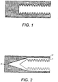
- the uni-axial orientation of fibres in the root structure presents a problem for the formation of the female part of the hub connection. This is because, if a female thread is cut directly into the "end grain" type uni-axial laminate of the root, the fibres will be cut resulting in a low pull out strength equal only to the shear strength of the resin. This is illustrated in Figure 1 which shows that the uni-axial threads have been cut in the vicinity of the female thread such that only the resin provides structural integrity to the thread formation.
- the metallic inserts are designed provide a large bond area so that, when the inserts are bonded into the uni-axial composite structure of the root, a bond having a sufficient pull out strength is achieved.
- the male bolts thread into the female threaded inserts to form the connection.
- the metallic inserts are either added after the composite root structure has been cured, or when the root structure is being laminated/infused.
- holes for the inserts are drilled into the root and the inserts are then bonded into position. This method requires specialist adhesive and equipment.
- the inserts are placed into the uncured laminate during "lay-up" and are then cured into the structure when the root composite is cured.
- metallic inserts solves the problem of cutting female threads directly into the uni-axial "end grain" of the root structure, they have their own problems. For example, structural problems can be caused by the thermal mismatch between the metallic inserts and the surrounding composite material, which have different thermal expansion coefficients. In addition, the metallic inserts have a higher stiffness than the surrounding composite material leading to problems with flexural mismatch in service.
- One way of countering these problems is to provide the metallic inserts with a tapered, more flexible, (sometimes referred to as carrot shaped) configuration to minimise the effect of material stiffness mismatch.
- the composite laminate in the region of the connection is made very thick, and hence stiffer, to further reduce the effect of the material stiffness mismatch.
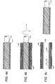
- a typical schematic example of a prior art metallic insert 1 embedded in a uni-axial composite material 2 is shown in Figure 2 . In practice approximately one third of the length of the insert is tapered. The taper of the inserts used in the current art can also be made by tapering down the amount of metallic material on the inside of the insert.
- the extra composite material required at the root end to compensate for the structural mismatch between the metallic inserts and the composite laminate has become very significant.
- the additional material contributes greatly to the overall mass, and hence cost, of the blade.
- the wall thickness of the composite laminate at the root end is in the case of 80mm and, for a 350mm metallic insert, the wall thickness must be maintained for approximately 500mm before it can begin to reduce. Because of the need for large amounts of composite material in the root structure, the cost of using more expensive materials, such as carbon fibre composite as required for larger blades, becomes prohibitive.
- DE 3640208 discloses a nut comprising a stack of discs each comprising a multi-axial fibre composite surrounded by a wound fibre.
- FR 2 863 321 discloses an insert for an end connection in a wind turbine. The insert is made of metal.
- an insert according to claim 1 there is provided an insert according to claim 1.
- the insert of the present invention is similar in thermal and mechanical properties to the composite material of the root of a wind blade. There is therefore significantly less mismatch between the thermal and mechanical behaviour of the insert with respect to the root than with prior art metallic inserts. This allows shorter inserts to be used, typically 160mm rather than 350mm for a 40m wind blade, and allows the root to have a smaller wall thickness. This can be a reduction from a wall thickness of about 80mm to approximately 60mm. In addition, because a better bond can be achieved between the like materials of the root and the insert, less inserts/bolts need to be used in the connection to the rotor hub leading to savings in material cost and maintenance costs. For a 40m wind blade, a weight saving of approximately 50% can be achieved in the root by using inserts according to the present invention.
- the sleeve comprises a plurality of radially spaced layers of multi-axial fibre fabric, this allows for more varied fibre lay-up configurations, thus providing more design freedom.
- the or each helically wound fibre layer overlies a layer of multi-axial fibre fabric. This has been found to provide a robust structure.
- the fibres of the or each helically wound fibre layer are preferably substantially aligned with a path described by the crests of the thread formation to provide additional strength in the threads of the insert.
- the sleeve comprises a fibre reinforced plastic.
- the sleeve comprises a filament wound fibre composite tube which can be readily purchased.
- the winding angle of 90% of the fibres is substantially equal to ⁇ , where ⁇ is the thread angle of the thread formation. The inventor has surprisingly found that this fibre arrangement enhances the pull out strength of threads subsequently cut into the tube.
- the fibres are preferably embedded within a cured resin matrix so that the insert can be provided as a stand alone component.
- the thread formation is integrally formed with the sleeve. This is advantageous as none of the fibres of the sleeve need to be cut to form the thread, thus providing a thread with greater structural integrity.
- the thread formation may be a cut thread formation for ease of manufacture.
- the inventor has surprisingly found that when a thread formation is cut into a sleeve having a multi-axial fibre arrangement the threads have sufficient pull out strength for wind turbine root connection applications.
- the insert may be located on a threaded mandrel.
- the insert preferably comprises a helical thread insert located within the thread formation to facilitate reusability of the insert.
- the helical thread insert may be a helical coil, but is more preferably a continuous sleeve with a female helical thread cut therein. This sleeve may also be provided with external male screw thread. This allows the helical thread insert to double-up as the mandrel. The sleeve will be significantly thinner than the metallic inserts of the prior art and therefore has a much lower stiffness.
- providing the sleeve comprises fabricating the sleeve on a threaded mandrel to integrally form the thread formation with the sleeve.
- Fabricating the sleeve preferably comprises positioning one or more layers of multi-axial fibre fabric on the threaded mandrel.
- a helically wound fibre layer is wound on each multi-axial fibre fabric layer .
- the or each helically wound fibre layer is preferably wound onto the mandrel so that the fibres are substantially aligned with a path described by the crests of the thread formation on the interior surface of the sleeve.
- the method may also further comprise impregnating the sleeve with resin and curing the resin to form a fibre reinforced plastic sleeve.
- the sleeve is a fibre reinforced plastic, preferably a filament wound fibre composite tube, and providing the thread formation comprises cutting a thread into the filament wound fibre composite tube.
- Positioning and securing the sleeve preferably comprises: cutting a hole in the uni-axial composite material; positioning the sleeve within the hole; and securing the sleeve in the hole with an adhesive.
- a typical adhesive would be an epoxy adhesive with a shear strength in the range of 25 -40 MPa.
- positioning and securing the sleeve comprises: positioning the sleeve within uni-axial material as the uni-axial material is being laid-up; impregnating the uni-axial material with resin; and curing the resin.
- the sleeve and the uni-axial material are impregnated with resin during the same process step. This has the advantage of securing the insert within the uni-axial material so that it becomes an integral part of the finished material.
- the sleeve may preferably be located on a mandrel during the positioning and securing. This provides support for the insert during the installation step.
- the sleeve is positioned within the uni-axial composite material such that the major axis of the sleeve is substantially parallel to the uni-axial fibres of the uni-axial composite material.
- the method preferably further comprises positioning a helical thread insert in the thread formation to facilitate reusability of the insert.
- the helical thread insert may be a helical coil, but is more preferably a continuous sleeve with a female helical thread cut therein. This sleeve may also be provided with external male screw thread. This allows the helical thread insert to double-up as the mandrel, thereby simplifying the process steps considerably.
- Figures 3a to 3c schematically illustrate a first method of fabricating an insert according to the present invention.
- Figure 3a shows a filament wound fibre composite tube 10 and a thread cutting tool 12.
- the winding angle of the majority of the fibres 20 of the tube 10 is approximately equal to ⁇ ( ⁇ 5°), where ⁇ is the thread angle of the thread cutting tool 12.
- the filament wound fibre composite tube 10 has 90% of its fibres wound at ⁇ .
- a tube having between 75% to 95% of its fibres wound at ⁇ may also be used.
- the winding angle of the fibres 20 is the acute angle that the fibres 20 make with the major axis 11 of the tube 10 when the tube 10 is viewed from the side ( Figure 3a ).
- the thread angle of the thread cutting tool 12 is the acute angle that the threads 17 make with the major axis 13 of the thread cutting tool 12 when the thread cutting tool is viewed from the side ( Figure 3a ).
- only fibres 20 having a winding angle of approximately + ⁇ are illustrated in Figure 3a .
- the tube 10 comprises fibres 20 having a winding angle of approximately ⁇ .
- the tube 10 may comprise standard e-glass and epoxy resin.
- any other suitable fibre composite material may be used such as e-glass and polyester or vinylester resin or carbon or aramid fibres.
- Figure 3b shows the filament wound fibre composite tube 10 during a thread tapping process.
- the thread cutting tool 12 is "screwed" into the tube 10 to cut a thread formation 25 in the interior surface of the tube 10.
- the thread cutting tool 12 is then removed ( Figure 3c ).
- the resulting component is a threaded insert 30 which comprises sleeve 35, formed from the tube 10, having thread formation 25 on its interior surface.
- the threads 26 of the thread formation have a thread angle which is equal to the thread angle of the thread cutting tool 12 and which is therefore approximately equal to the winding angle of the fibres 20.
- the insert 30 is bonded into the uni-axial material of the root end of a wind blade as will be described in greater detail below.
- Figures 4a to 4c schematically illustrate the general principal of a second, alternative, method of fabricating an insert in accordance with the present invention.
- Figure 4a shows a threaded mandrel 112 onto which layers 120 of fibres are positioned ( Figure 4b ) to build up a sleeve 135.
- the sleeve 135, which is built up on the threaded mandrel 112 also has a thread formation 125 on its interior surface.
- layers 220 of multi-axial fibre fabric are positioned on the mandrel and a uni-axial fibre tow 221 is wound over each layer of multi-axial fibre fabric in order to pull the multi-axial fibre fabric into the thread form on the mandrel.
- other methods, discussed below, of building up a sleeve 135 on a threaded mandrel may be used without departing from the present invention.
- the sleeve 135 Once the sleeve 135 has been built up, by any appropriate means, on the threaded mandrel 112 it can be infused with resin, cured and removed from the threaded mandrel 112 to form a pre-cured insert 130.
- the sleeve 135 may be supplied and installed whilst still mounted on the threaded mandrel without any resin having been infused.
- the insert 130 is infused with resin and cured whilst in-situ as will be described in greater detail below.
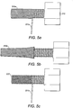
- Figures 5a to 5c show a preferred method of fabricating an insert in accordance with the present invention.
- a layer 220a of low tex (typically 3 - 24k) multi-axial fibre fabric is positioned over a threaded mandrel 212.
- the multi-axial fibre fabric is preferably a fibre braid.
- a sheet fabric, or helically wound tape may also be used.
- a uni-axial low tex fibre tow comprising a plurality of uni-axial fibres, is wound over the multi-axial fibre fabric layer 220a to form a helically wound fibre layer 221a.
- the uni-axial fibre tow is wound onto the mandrel 212 so that it lies within the grooves of the thread formation on the mandrel. This pulls the layer 220a of multi-axial fibre fabric into the thread formation and helps to ensure that the thread formation on the finished insert is a true "mould" of the thread formation in the threaded mandrel 212.
- the fibres of the helically wound fibre layer are substantially aligned with a path defined by the crests 127 ( Figure 4c ) of the thread formation on the interior surface of the sleeve 235.
- the helically wound fibre layer 221a is not continuous in the axial direction such that it does not totally cover the multi-axial fibre fabric layer below.
- Figure 5b shows a third process step in which a second layer 220b of multi-axial fibre fabric is positioned over the mandrel 212.
- a fourth process step shown in Figure 5c , an optional guide thread 222 is wound over the second layer 220b of multi-axial fibre fabric in order to pull the second layer 220b of multi-axial fibre fabric into the form of the threaded mandrel 212.
- the guide thread 222 is then over-wound by a second helically wound fibre layer 221b. This process is repeated 4 or 5 times until the threads of the threaded mandrel 212 are completely filled by the fibre laminate structure which form a sleeve 235.
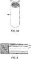
- the sleeve 235 is impregnated with resin and cured before being removed from the threaded mandrel, by unscrewing, to produce a pre-cured insert 230 ( Figure 5d ).
- the insert 230 is supplied and installed whilst still mounted on the threaded mandrel without any resin having been infused.
- the preferred method of building up the sleeve 135, 235 of the insert 130, 230 on a threaded mandrel is as described with reference to Figures 5a to 5c .
- other methods of building up a fibre sleeve on a threaded mandrel may also be used.
- only one layer of multi-axial fibre fabric may be used, said layer being overlaid with layers of wound uni-axial fibres and/or filament wound layers.
- the sleeve may be built up only of multi-axial fibre layers. In such a case a vacuum bag, or external female mandrel, may be used to ensure that the fibre layers properly lie within the thread formation of the threaded mandrel.
- a fibre composite tube made up of layers of multi-axial fibre fabric, wound uni-axial fibre and filament wound fibres, or any combination thereof, laid-up on a plane cylindrical mandrel.
- the sleeve is infused with resin and cured before being removed from the mandrel and threaded with a thread cutting tool such as is shown in Figures 3a to 3c .
- the pre-cured inserts when made by any method, may be installed into the uni-axial composite material of the root of a wind blade in two ways. In the first method a hole is drilled in the root end and the insert is bonded into the hole with adhesive. In an alternative method, the pre-cured insert may be positioned in the uni-axial material of the root during lay-up. The root is then infused with resin and cured to secure the insert in place.
- the insert is positioned in the uni-axial material of the root during lay-up whilst still supported on the mandrel.
- the root and insert are then infused with resin together in the same process step and cured.
- the mandrel may then be removed.
- Figure 6 illustrates an insert, when made/installed by any method, positioned in a uni-axial composite material. As shown, the insert is installed so that its major axis 11 is substantially parallel to the direction of the uni-axial fibres.
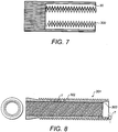
- a metallic thread insert 300 ( Figure 7 ) is located within the thread formation on the interior surface of the sleeve.
- the thread insert 300 initially has a diameter which is slightly larger than the thread formation in the composite insert so that when it is screwed into the thread formation the insert is compressed and held in place by an interference fit.
- the thread insert 300 shown in Fig. 7 is a helical coil.
- An alternative insert 301 is shown in Fig. 8 .
- This is now a thin walled metal sleeve.
- the sleeve is provided with an external male screw thread 302 which faces the corresponding female thread of the insert and replicates the thread of the mandrel.
- the sleeve has an internal female screw thread 303 which engages with the bolt.
- the thickness T between the troughs of the two screw threads is preferably less than 5mm.
- the metal sleeve not only provides the surface which engages with the bolt, but acts as the mandrel around which the multi-axial insert is formed.
- the thread insert 301 bears some superficial resemblance to the metal insert of the prior art as depicted in Fig. 2 .
- the significant difference is that, in Fig. 2 , the sleeve 1 is retained in the uni-axial composite material by virtue of a bonded connection between the sleeve and the uni-axial composite material. This requires it to be significantly thicker and longer than the insert 301 which is retained in a threaded multi-axial surround.
- the problems of the thermal mismatch and flexural mismatch identified in relation to the prior art can therefore be significantly reduced.
- there is no need for the tapered end shown in Fig. 2 which is the greatest contributor to the problems of thermal and flexural mismatch.
- the other significant difference is that the prior art metallic inserts are significantly stiffer, whereas in this example the inserts are designed to be very thin walled and therefore be very flexible when compared to the prior art inserts.
- the whole of the interior surface of the insert may comprise a thread formation.
- the thread formation exists only at one end of the insert. Such an embodiment may be useful when it is desired to increase the bond area provided on the external surface of the insert.
- the insert of the present invention has been described with reference to installation within the uni-axial material of the root of a wind blade, it will be appreciated that the insert may also be used in other areas of technology where bolted connections need to be made. Similarly, it will be understood that the insert may be installed in non-uni-axial composite materials or other types of material.
Description
- The present invention relates to an insert for forming a high load carrying end connection in a uni-axial composite material. The present invention also relates to a method of forming an end connection in a uni-axial composite material using the insert. The present invention is exemplified by an insert for a root end of a wind turbine blade. However, the insert is also suitable for use in other applications and with other materials.
- In large horizontal axis wind turbines the wind turbine blades are connected to the rotor hub by a number of bolt attachment points. The hub end of the wind turbine blades (the root) is cylindrical in section and typically has a diameter of 1500 mm to 3000 mm. Approximately 60 to 80 bolts connect the blade to a radial pitch bearing within the rotor hub. The bolts are typically M30 to M40 size and each is required to withstand a pullout force of the order of 200 to 4000 kN. The bolts are arranged circumferentially around the root.
- The female part of the connection must be located in the root part of the blade so that the male bolts can be accessed for maintenance from the hub side when in service to ensure that there is no failure in the connection.
- The root of the blade is typically manufactured from fibre reinforced plastic, typically glass fibre in epoxy, vinylester or polyester resin. The predominant fibre orientation in the root structure is uni-axial with the fibres running parallel to the axis of the blade/root cylinder, with very few fibres in the radial direction. The uni-axial orientation of fibres in the root structure presents a problem for the formation of the female part of the hub connection. This is because, if a female thread is cut directly into the "end grain" type uni-axial laminate of the root, the fibres will be cut resulting in a low pull out strength equal only to the shear strength of the resin. This is illustrated in
Figure 1 which shows that the uni-axial threads have been cut in the vicinity of the female thread such that only the resin provides structural integrity to the thread formation. - To overcome this problem long metallic female threaded inserts have been used. The metallic inserts are designed provide a large bond area so that, when the inserts are bonded into the uni-axial composite structure of the root, a bond having a sufficient pull out strength is achieved. The male bolts thread into the female threaded inserts to form the connection.
- The metallic inserts are either added after the composite root structure has been cured, or when the root structure is being laminated/infused. In the first method, holes for the inserts are drilled into the root and the inserts are then bonded into position. This method requires specialist adhesive and equipment. In the alternative method, the inserts are placed into the uncured laminate during "lay-up" and are then cured into the structure when the root composite is cured.
- Although the use of metallic inserts solves the problem of cutting female threads directly into the uni-axial "end grain" of the root structure, they have their own problems. For example, structural problems can be caused by the thermal mismatch between the metallic inserts and the surrounding composite material, which have different thermal expansion coefficients. In addition, the metallic inserts have a higher stiffness than the surrounding composite material leading to problems with flexural mismatch in service.
- One way of countering these problems is to provide the metallic inserts with a tapered, more flexible, (sometimes referred to as carrot shaped) configuration to minimise the effect of material stiffness mismatch. In addition, the composite laminate in the region of the connection is made very thick, and hence stiffer, to further reduce the effect of the material stiffness mismatch. A typical schematic example of a prior art
metallic insert 1 embedded in a uni-axialcomposite material 2 is shown inFigure 2 . In practice approximately one third of the length of the insert is tapered. The taper of the inserts used in the current art can also be made by tapering down the amount of metallic material on the inside of the insert. - As wind turbines have got larger, the extra composite material required at the root end to compensate for the structural mismatch between the metallic inserts and the composite laminate has become very significant. The additional material contributes greatly to the overall mass, and hence cost, of the blade. For a 40 m wind blade, the wall thickness of the composite laminate at the root end is in the case of 80mm and, for a 350mm metallic insert, the wall thickness must be maintained for approximately 500mm before it can begin to reduce. Because of the need for large amounts of composite material in the root structure, the cost of using more expensive materials, such as carbon fibre composite as required for larger blades, becomes prohibitive.
-
DE 3640208 discloses a nut comprising a stack of discs each comprising a multi-axial fibre composite surrounded by a wound fibre.FR 2 863 321 - According to a first aspect of the present invention there is provided an insert according to
claim 1. The insert of the present invention is similar in thermal and mechanical properties to the composite material of the root of a wind blade. There is therefore significantly less mismatch between the thermal and mechanical behaviour of the insert with respect to the root than with prior art metallic inserts. This allows shorter inserts to be used, typically 160mm rather than 350mm for a 40m wind blade, and allows the root to have a smaller wall thickness. This can be a reduction from a wall thickness of about 80mm to approximately 60mm. In addition, because a better bond can be achieved between the like materials of the root and the insert, less inserts/bolts need to be used in the connection to the rotor hub leading to savings in material cost and maintenance costs. For a 40m wind blade, a weight saving of approximately 50% can be achieved in the root by using inserts according to the present invention. - As the sleeve comprises a plurality of radially spaced layers of multi-axial fibre fabric, this allows for more varied fibre lay-up configurations, thus providing more design freedom.
- Preferably the or each helically wound fibre layer overlies a layer of multi-axial fibre fabric. This has been found to provide a robust structure. The fibres of the or each helically wound fibre layer are preferably substantially aligned with a path described by the crests of the thread formation to provide additional strength in the threads of the insert.
- In an alternative example the sleeve comprises a fibre reinforced plastic. Preferably, the sleeve comprises a filament wound fibre composite tube which can be readily purchased. Preferably the winding angle of 90% of the fibres is substantially equal to ±θ, where θ is the thread angle of the thread formation. The inventor has surprisingly found that this fibre arrangement enhances the pull out strength of threads subsequently cut into the tube.
- The fibres are preferably embedded within a cured resin matrix so that the insert can be provided as a stand alone component.
- In one example the thread formation is integrally formed with the sleeve. This is advantageous as none of the fibres of the sleeve need to be cut to form the thread, thus providing a thread with greater structural integrity.
- Alternatively the thread formation may be a cut thread formation for ease of manufacture. The inventor has surprisingly found that when a thread formation is cut into a sleeve having a multi-axial fibre arrangement the threads have sufficient pull out strength for wind turbine root connection applications.
- The insert may be located on a threaded mandrel.
- The insert preferably comprises a helical thread insert located within the thread formation to facilitate reusability of the insert. The helical thread insert may be a helical coil, but is more preferably a continuous sleeve with a female helical thread cut therein. This sleeve may also be provided with external male screw thread. This allows the helical thread insert to double-up as the mandrel. The sleeve will be significantly thinner than the metallic inserts of the prior art and therefore has a much lower stiffness.
- According to a second aspect of the present invention there is provided a method according to claim 9. In a preferred example, providing the sleeve comprises fabricating the sleeve on a threaded mandrel to integrally form the thread formation with the sleeve.
- Fabricating the sleeve preferably comprises positioning one or more layers of multi-axial fibre fabric on the threaded mandrel. Preferably a helically wound fibre layer is wound on each multi-axial fibre fabric layer .
- The or each helically wound fibre layer is preferably wound onto the mandrel so that the fibres are substantially aligned with a path described by the crests of the thread formation on the interior surface of the sleeve.
- The method may also further comprise impregnating the sleeve with resin and curing the resin to form a fibre reinforced plastic sleeve.
- In an alternative example, the sleeve is a fibre reinforced plastic, preferably a filament wound fibre composite tube, and providing the thread formation comprises cutting a thread into the filament wound fibre composite tube.
- Positioning and securing the sleeve preferably comprises: cutting a hole in the uni-axial composite material; positioning the sleeve within the hole; and securing the sleeve in the hole with an adhesive. A typical adhesive would be an epoxy adhesive with a shear strength in the range of 25 -40 MPa.
- In an alternative example, positioning and securing the sleeve comprises: positioning the sleeve within uni-axial material as the uni-axial material is being laid-up; impregnating the uni-axial material with resin; and curing the resin.
- In one example, the sleeve and the uni-axial material are impregnated with resin during the same process step. This has the advantage of securing the insert within the uni-axial material so that it becomes an integral part of the finished material.
- The sleeve may preferably be located on a mandrel during the positioning and securing. This provides support for the insert during the installation step.
- Preferably the sleeve is positioned within the uni-axial composite material such that the major axis of the sleeve is substantially parallel to the uni-axial fibres of the uni-axial composite material.
- The method preferably further comprises positioning a helical thread insert in the thread formation to facilitate reusability of the insert. The helical thread insert may be a helical coil, but is more preferably a continuous sleeve with a female helical thread cut therein. This sleeve may also be provided with external male screw thread. This allows the helical thread insert to double-up as the mandrel, thereby simplifying the process steps considerably.
- Examples of the present invention will now be described with reference to the following drawings in which:
-
Figure 1 is a schematic cross-sectional drawing of a female thread cut directly into the end of a uni-axial composite material; -
Figure 2 is a schematic cross-sectional drawing of a prior art metallic insert bonded into the end of a uni-axial composite material; -
Figure 3a is a schematic cross-sectional drawing of a filament wound composite tube and a schematic drawing of a female thread cutting tool before a thread cutting operation; -
Figure 3b shows the components ofFigure 3a during the thread cutting operation; -
Figure 3c shows the components ofFigure 3a after the thread cutting operation is complete; -
Figure 4a is a schematic drawing of a threaded mandrel; -
Figure 4b shows the threaded mandrel ofFigure 4a with a cross-sectional schematic representation an insert according to the present invention during fabrication; -
Figure 4c shows a cross-sectional schematic drawing of the insert ofFigure 4b when removed from the threaded mandrel; -
Figure 5a is a drawing of the first stages of fabrication of an insert in accordance with the present invention; -
Figure 5b is a drawing of the second stage of fabrication of the insert ofFigure 5a ; -
Figure 5c is a drawing of the later stages of fabrication of the insert ofFigure 5a ; -
Figure 5d is a drawing of the completed insert ofFigure 5a ; -
Figure 6 is a schematic cross-sectional drawing of an insert according to the present invention bonded into the end of a uni-axial composite material; and -
Figure 7 is a schematic cross-sectional drawing of the insert ofFigure 6 with a thread insert. -
Figures 3a to 3c schematically illustrate a first method of fabricating an insert according to the present invention.Figure 3a shows a filament wound fibrecomposite tube 10 and athread cutting tool 12. The winding angle of the majority of thefibres 20 of thetube 10 is approximately equal to ±θ (±5°), where θ is the thread angle of thethread cutting tool 12. Ideally, the filament wound fibrecomposite tube 10 has 90% of its fibres wound at ±θ. However, a tube having between 75% to 95% of its fibres wound at ±θ may also be used. - For clarity, the winding angle of the
fibres 20 is the acute angle that thefibres 20 make with themajor axis 11 of thetube 10 when thetube 10 is viewed from the side (Figure 3a ). Similarly, the thread angle of thethread cutting tool 12 is the acute angle that thethreads 17 make with themajor axis 13 of thethread cutting tool 12 when the thread cutting tool is viewed from the side (Figure 3a ). For the purposes of clarity in the Figures, onlyfibres 20 having a winding angle of approximately +θ are illustrated inFigure 3a . However, it will be understood that thetube 10 comprisesfibres 20 having a winding angle of approximately ±θ. - In one example, the
tube 10 may comprise standard e-glass and epoxy resin. However, any other suitable fibre composite material may be used such as e-glass and polyester or vinylester resin or carbon or aramid fibres. -
Figure 3b shows the filament wound fibrecomposite tube 10 during a thread tapping process. During the thread tapping process thethread cutting tool 12 is "screwed" into thetube 10 to cut athread formation 25 in the interior surface of thetube 10. Thethread cutting tool 12 is then removed (Figure 3c ). The resulting component is a threadedinsert 30 which comprisessleeve 35, formed from thetube 10, havingthread formation 25 on its interior surface. Thethreads 26 of the thread formation have a thread angle which is equal to the thread angle of thethread cutting tool 12 and which is therefore approximately equal to the winding angle of thefibres 20. In use, theinsert 30 is bonded into the uni-axial material of the root end of a wind blade as will be described in greater detail below. -
Figures 4a to 4c schematically illustrate the general principal of a second, alternative, method of fabricating an insert in accordance with the present invention.Figure 4a shows a threadedmandrel 112 onto which layers 120 of fibres are positioned (Figure 4b ) to build up asleeve 135. - Because the
mandrel 112 has a threadedformation 117 on its outer surface, thesleeve 135, which is built up on the threadedmandrel 112, also has athread formation 125 on its interior surface. In a preferred method of fabrication, described in greater detail below with reference toFigures 5a to 5d , layers 220 of multi-axial fibre fabric are positioned on the mandrel and a uni-axial fibre tow 221 is wound over each layer of multi-axial fibre fabric in order to pull the multi-axial fibre fabric into the thread form on the mandrel. However, other methods, discussed below, of building up asleeve 135 on a threaded mandrel may be used without departing from the present invention. - Once the
sleeve 135 has been built up, by any appropriate means, on the threadedmandrel 112 it can be infused with resin, cured and removed from the threadedmandrel 112 to form apre-cured insert 130. Alternatively thesleeve 135 may be supplied and installed whilst still mounted on the threaded mandrel without any resin having been infused. In this case theinsert 130 is infused with resin and cured whilst in-situ as will be described in greater detail below. -
Figures 5a to 5c show a preferred method of fabricating an insert in accordance with the present invention. As shown inFigure 5a , in a first process step alayer 220a of low tex (typically 3 - 24k) multi-axial fibre fabric is positioned over a threadedmandrel 212. The multi-axial fibre fabric is preferably a fibre braid. However, a sheet fabric, or helically wound tape may also be used. - In a second process step, a uni-axial low tex fibre tow, comprising a plurality of uni-axial fibres, is wound over the multi-axial
fibre fabric layer 220a to form a helicallywound fibre layer 221a. As can be seen inFigure 5a , the uni-axial fibre tow is wound onto themandrel 212 so that it lies within the grooves of the thread formation on the mandrel. This pulls thelayer 220a of multi-axial fibre fabric into the thread formation and helps to ensure that the thread formation on the finished insert is a true "mould" of the thread formation in the threadedmandrel 212. Thus the fibres of the helically wound fibre layer are substantially aligned with a path defined by the crests 127 (Figure 4c ) of the thread formation on the interior surface of thesleeve 235. As can be seen fromFigure 5a , the helicallywound fibre layer 221a is not continuous in the axial direction such that it does not totally cover the multi-axial fibre fabric layer below. -
Figure 5b shows a third process step in which asecond layer 220b of multi-axial fibre fabric is positioned over themandrel 212. In a fourth process step, shown inFigure 5c , anoptional guide thread 222 is wound over thesecond layer 220b of multi-axial fibre fabric in order to pull thesecond layer 220b of multi-axial fibre fabric into the form of the threadedmandrel 212. Theguide thread 222 is then over-wound by a second helicallywound fibre layer 221b. This process is repeated 4 or 5 times until the threads of the threadedmandrel 212 are completely filled by the fibre laminate structure which form asleeve 235. In one example, thesleeve 235 is impregnated with resin and cured before being removed from the threaded mandrel, by unscrewing, to produce a pre-cured insert 230 (Figure 5d ). In an alternative example, described below, theinsert 230 is supplied and installed whilst still mounted on the threaded mandrel without any resin having been infused. - As mentioned above, the preferred method of building up the
sleeve insert Figures 5a to 5c . However, other methods of building up a fibre sleeve on a threaded mandrel may also be used. For example, only one layer of multi-axial fibre fabric may be used, said layer being overlaid with layers of wound uni-axial fibres and/or filament wound layers. Alternatively, the sleeve may be built up only of multi-axial fibre layers. In such a case a vacuum bag, or external female mandrel, may be used to ensure that the fibre layers properly lie within the thread formation of the threaded mandrel. - In a further alternative method, a fibre composite tube made up of layers of multi-axial fibre fabric, wound uni-axial fibre and filament wound fibres, or any combination thereof, laid-up on a plane cylindrical mandrel. In this case the sleeve is infused with resin and cured before being removed from the mandrel and threaded with a thread cutting tool such as is shown in
Figures 3a to 3c . - The pre-cured inserts, when made by any method, may be installed into the uni-axial composite material of the root of a wind blade in two ways. In the first method a hole is drilled in the root end and the insert is bonded into the hole with adhesive. In an alternative method, the pre-cured insert may be positioned in the uni-axial material of the root during lay-up. The root is then infused with resin and cured to secure the insert in place.
- For inserts comprising no resin, the insert is positioned in the uni-axial material of the root during lay-up whilst still supported on the mandrel. The root and insert are then infused with resin together in the same process step and cured. The mandrel may then be removed.
-
Figure 6 illustrates an insert, when made/installed by any method, positioned in a uni-axial composite material. As shown, the insert is installed so that itsmajor axis 11 is substantially parallel to the direction of the uni-axial fibres. - In practice, it is preferable that the thread of the insert be re-useable to allow connecting bolts to be installed/removed a number of times for service and maintenance. In order to improve the re-usability of the inserts, a metallic thread insert 300 (
Figure 7 ) is located within the thread formation on the interior surface of the sleeve. Thethread insert 300 initially has a diameter which is slightly larger than the thread formation in the composite insert so that when it is screwed into the thread formation the insert is compressed and held in place by an interference fit. - The
thread insert 300 shown inFig. 7 is a helical coil. Analternative insert 301 is shown inFig. 8 . Rather than being a helical coil, this is now a thin walled metal sleeve. The sleeve is provided with an externalmale screw thread 302 which faces the corresponding female thread of the insert and replicates the thread of the mandrel. The sleeve has an internalfemale screw thread 303 which engages with the bolt. The thickness T between the troughs of the two screw threads is preferably less than 5mm. The metal sleeve not only provides the surface which engages with the bolt, but acts as the mandrel around which the multi-axial insert is formed. The forming process is the same as described above in relation toFigs. 5a-5c , but, in this case, there is no need to subsequently remove the mandrel from the insert. This example retains all of the benefits of the previous examples in that it retains the interface between the uni-axial surround and the multi-axial sleeve. However, it is readily reusable given the presence of the metal insert which engages with the bolt and is simple to manufacture. - The
thread insert 301 bears some superficial resemblance to the metal insert of the prior art as depicted inFig. 2 . However, the significant difference is that, inFig. 2 , thesleeve 1 is retained in the uni-axial composite material by virtue of a bonded connection between the sleeve and the uni-axial composite material. This requires it to be significantly thicker and longer than theinsert 301 which is retained in a threaded multi-axial surround. The problems of the thermal mismatch and flexural mismatch identified in relation to the prior art can therefore be significantly reduced. In particular, there is no need for the tapered end shown inFig. 2 which is the greatest contributor to the problems of thermal and flexural mismatch. The other significant difference is that the prior art metallic inserts are significantly stiffer, whereas in this example the inserts are designed to be very thin walled and therefore be very flexible when compared to the prior art inserts. - It is not necessary for the whole of the interior surface of the insert to comprise a thread formation. In one example (not shown) the thread formation exists only at one end of the insert. Such an embodiment may be useful when it is desired to increase the bond area provided on the external surface of the insert.
- Although the insert of the present invention has been described with reference to installation within the uni-axial material of the root of a wind blade, it will be appreciated that the insert may also be used in other areas of technology where bolted connections need to be made. Similarly, it will be understood that the insert may be installed in non-uni-axial composite materials or other types of material.
Claims (14)
- An insert (30) for forming an end connection in a substantially uni-axial composite material, the insert comprising a sleeve (10, 120, 301) characterised in that the sleeve comprises a plurality of fibres having a multi-axial arrangement, wherein at least a portion of the interior surface of the sleeve comprises a thread formation (25, 303), wherein the sleeve comprises a plurality of layers of multi-axial fibre fabric, and wherein the sleeve further comprises at least one helically wound fibre layer (221a, 221b).
- An insert (30) according to claim 1, wherein the at least one helically wound fibre layer overlies a layer of multi-axial fibre fabric.
- An insert (30) according to any preceding claim, wherein the thread formation (25, 303) is integrally formed with the sleeve.
- An insert (30) according to claim 3, wherein the fibres of the at least one helically wound fibre layer (221a, 211b) are substantially aligned with a path described by the crests of the thread formation.
- An insert (30) according to any one of claims 1 to 4, further comprising a helical thread insert (300) located within the thread formation (303), wherein the helical thread insert (300) is a continuous sleeve with male and female screw threaded portions, and has a wall thickness of less than 5mm between the troughs of the male and female screw threaded portions.
- A combination of an insert (30) according to any of claims 1 to 4 and a threaded mandrel (17, 112), the insert (30) being located on the threaded mandrel (17, 112).
- An end connection comprising at least one insert (30) as defined in any of claims 1 to 4.
- A wind turbine blade comprising a plurality of inserts (30) as defined in any of claims 1 to 4 embedded within a root of the wind turbine blade.
- A method of forming an end connection in a substantially uni-axial composite material, the method being characterised by:providing a sleeve (10, 120, 301) comprising a plurality of fibres having a multi-axial arrangement;providing a thread formation (25, 303) on at least a portion of the interior surface of the sleeve;positioning and securing the sleeve within the uni-axial composite material; andhelically winding at least one wound fibre layer (221a, 221b) on a least one multi-axial fibre fabric layer.
- A method according to claim 9, wherein providing the sleeve (10, 120, 301) comprises fabricating the sleeve on a mandrel (17, 112).
- A method according to claim 10, wherein fabricating the sleeve (10, 120, 301) comprises positioning at least one layer of multi-axial fibre fabric on the mandrel (17, 112).
- A method according to claim 11, wherein fabricating the sleeve (10, 120, 301) comprises positioning a plurality of radially spaced layers of multi-axial fibre fabric on the mandrel (17, 112).
- A method according to any of claims 10 to 12, wherein the mandrel (17, 112) is a thread mandrel, and wherein the or each helically wound fibre layer (221a, 221b) is wound so that the fibres are substantially aligned with a path described by the crest of the thread formation on the interior surface of the sleeve (10, 120, 301).
- A method according to any of claims 9 to 13, wherein positioning and securing the sleeve (10, 120, 301) comprises:positioning the sleeve (10, 120 301) within uni-axial material as the uni-axial material is being laid-up;impregnating the uni-axial material with resin; andcuring the resin.
Priority Applications (1)
| Application Number | Priority Date | Filing Date | Title |
|---|---|---|---|
| PL09737113T PL2349703T3 (en) | 2008-10-08 | 2009-10-07 | An insert and method for forming an end connection in a uni-axial composite material |
Applications Claiming Priority (2)
| Application Number | Priority Date | Filing Date | Title |
|---|---|---|---|
| GBGB0818467.3A GB0818467D0 (en) | 2008-10-08 | 2008-10-08 | An insert for forming an end connection in a uni-axial composite material |
| PCT/GB2009/002397 WO2010041008A1 (en) | 2008-10-08 | 2009-10-07 | An insert and method for forming an end connection in a uni -axial composite material |
Publications (2)
| Publication Number | Publication Date |
|---|---|
| EP2349703A1 EP2349703A1 (en) | 2011-08-03 |
| EP2349703B1 true EP2349703B1 (en) | 2017-07-19 |
Family
ID=40042509
Family Applications (1)
| Application Number | Title | Priority Date | Filing Date |
|---|---|---|---|
| EP09737113.2A Active EP2349703B1 (en) | 2008-10-08 | 2009-10-07 | An insert and method for forming an end connection in a uni-axial composite material |
Country Status (10)
| Country | Link |
|---|---|
| US (1) | US9555588B2 (en) |
| EP (1) | EP2349703B1 (en) |
| JP (1) | JP5784494B2 (en) |
| CN (1) | CN102224001B (en) |
| BR (1) | BRPI0919574A2 (en) |
| DK (1) | DK2349703T3 (en) |
| ES (1) | ES2639953T3 (en) |
| GB (1) | GB0818467D0 (en) |
| PL (1) | PL2349703T3 (en) |
| WO (1) | WO2010041008A1 (en) |
Cited By (1)
| Publication number | Priority date | Publication date | Assignee | Title |
|---|---|---|---|---|
| US11530679B2 (en) | 2017-12-08 | 2022-12-20 | Vestas Wind Systems A/S | Insert for a wind turbine blade root |
Families Citing this family (37)
| Publication number | Priority date | Publication date | Assignee | Title |
|---|---|---|---|---|
| EP2138716B2 (en) * | 2008-06-27 | 2024-02-14 | Siemens Gamesa Renewable Energy Innovation & Technology, S.L. | Blade insert |
| CN102022255A (en) * | 2009-09-23 | 2011-04-20 | 苏州红枫风电模具有限公司 | Insertion piece for wind turbine blade root |
| GB201109412D0 (en) | 2011-06-03 | 2011-07-20 | Blade Dynamics Ltd | A wind turbine rotor |
| EP2554834B1 (en) | 2011-08-02 | 2016-07-13 | Alstom Wind, S.L.U. | Rotor for a wind turbine |
| GB201118419D0 (en) * | 2011-10-25 | 2011-12-07 | Blade Dynamics Ltd | A method of making a root end joint of a wind turbine blade and a root segment for such a joint |
| EP2592264B1 (en) * | 2011-11-11 | 2014-12-31 | Nordex Energy GmbH | Blade connection for a rotor blade of a wind energy assembly |
| MX2014014231A (en) * | 2012-05-22 | 2015-08-06 | Continental Structural Plastics Inc | Compression molding fastener. |
| GB201215004D0 (en) | 2012-08-23 | 2012-10-10 | Blade Dynamics Ltd | Wind turbine tower |
| GB201217210D0 (en) | 2012-09-26 | 2012-11-07 | Blade Dynamics Ltd | A metod of forming a structural connection between a spar cap fairing for a wind turbine blade |
| GB201217212D0 (en) | 2012-09-26 | 2012-11-07 | Blade Dynamics Ltd | Windturbine blade |
| WO2014076183A1 (en) * | 2012-11-14 | 2014-05-22 | Xemc Darwind B.V. | A method of manufacturing a blade element |
| EP2954199B1 (en) * | 2013-02-07 | 2019-08-07 | LM WP Patent Holding A/S | Limp, elongate element with glass staple fibres |
| US9464622B2 (en) | 2013-05-31 | 2016-10-11 | General Electric Company | Rotor blade assembly having a stiffening root insert |
| DE102014008558B4 (en) * | 2014-05-28 | 2019-09-12 | Windnovation Engineering Solutions Gmbh | Rotor blade connection |
| DE102014221966B4 (en) | 2014-10-28 | 2018-07-12 | Senvion Gmbh | Method for producing a rotor blade of a wind energy plant |
| US9745956B2 (en) | 2014-12-10 | 2017-08-29 | General Electric Company | Spar cap for a wind turbine rotor blade |
| US10190571B2 (en) | 2015-07-01 | 2019-01-29 | General Electric Company | Ring insert for a wind turbine rotor blade |
| US10060411B2 (en) | 2015-07-22 | 2018-08-28 | General Electric Company | Rotor blade root assembly for a wind turbine |
| US9970304B2 (en) | 2015-07-22 | 2018-05-15 | General Electric Company | Rotor blade root assembly for a wind turbine |
| JP6394912B2 (en) * | 2015-09-14 | 2018-09-26 | Jfeスチール株式会社 | Furnace protection stave |
| EP3380313B1 (en) * | 2015-11-26 | 2019-08-07 | Vestas Wind Systems A/S | Improvements relating to the manufacture of wind turbine blades |
| US11572861B2 (en) | 2017-01-31 | 2023-02-07 | General Electric Company | Method for forming a rotor blade for a wind turbine |
| US10046515B1 (en) * | 2017-03-30 | 2018-08-14 | General Electric Company | Method of forming wind turbine rotor blade root portions |
| US10557455B2 (en) | 2017-06-27 | 2020-02-11 | General Electric Company | Root insert and a wind turbine having wind turbine blades with root inserts |
| US10677216B2 (en) | 2017-10-24 | 2020-06-09 | General Electric Company | Wind turbine rotor blade components formed using pultruded rods |
| GB2569297A (en) * | 2017-12-08 | 2019-06-19 | Vestas Wind Sys As | Wind turbine blade root bushing replacement method and insert |
| GB2569295A (en) * | 2017-12-08 | 2019-06-19 | Vestas Wind Sys As | A replacement insert for repair of a joint connecting a wind turbine rotor blade to a rotor hub |
| JP7236725B2 (en) * | 2018-01-11 | 2023-03-10 | 株式会社タカイコーポレーション | Fiber-reinforced resin bolt manufacturing method and fiber-reinforced resin bolt |
| RU2680513C1 (en) * | 2018-01-30 | 2019-02-21 | Акционерное общество "Авангард" (АО "Авангард") | Method of threading in uncured composition-fiber material |
| US11738530B2 (en) | 2018-03-22 | 2023-08-29 | General Electric Company | Methods for manufacturing wind turbine rotor blade components |
| ES2935465T3 (en) * | 2018-04-30 | 2023-03-07 | Vestas Wind Sys As | Rotor for a wind turbine with a pitch regulating bearing unit |
| GB2575105A (en) | 2018-06-29 | 2020-01-01 | Airbus Operations Ltd | A duct stringer |
| US11719222B2 (en) * | 2018-08-03 | 2023-08-08 | General Electric Company | Method of joining wind turbine rotor blade segments via structural members |
| CN112912616A (en) * | 2018-11-01 | 2021-06-04 | 通用电气公司 | Wind turbine rotor blade joint constructed of dissimilar materials |
| NL2024870B1 (en) * | 2020-02-10 | 2021-09-15 | Viventus Holding B V | IMPROVED BUSHING FOR CONNECTING A WIND TURBINE BLADE ROOT TO A TURBINE HUB |
| RU2753394C1 (en) * | 2020-10-13 | 2021-08-16 | федеральное государственное автономное образовательное учреждение высшего образования "Пермский национальный исследовательский политехнический университет" | Method for obtaining holes in composite material and device for its implementation |
| EP4119790A1 (en) * | 2021-07-12 | 2023-01-18 | General Electric Renovables España S.L. | Wind turbine blade assembly and methods |
Family Cites Families (18)
| Publication number | Priority date | Publication date | Assignee | Title |
|---|---|---|---|---|
| US2710026A (en) | 1950-07-19 | 1955-06-07 | Continental Diamond Fibre Co | Molded tapered tubes and method of making same |
| US2943967A (en) * | 1956-06-29 | 1960-07-05 | Minnesota Mining & Mfg | Reinforced plastic screw threads |
| US3283050A (en) * | 1965-04-06 | 1966-11-01 | Universal Moulded Fiber Glass | Method and apparatus for making continuous lengths of threaded fiber reinforced resin articles |
| US3495494A (en) * | 1967-07-11 | 1970-02-17 | Cp Corp | Threaded plastic member with a reinforced thread |
| US3713932A (en) * | 1970-12-15 | 1973-01-30 | Rex Chainbelt Inc | Method of making low friction fabric lined nuts of multiple length construction |
| US4063838A (en) * | 1976-05-07 | 1977-12-20 | Fiber Glass Systems, Inc. | Rod construction and method of forming the same |
| US4717302A (en) * | 1984-06-18 | 1988-01-05 | Tiodize Company, Inc. | Composite fastener |
| DE3640208A1 (en) | 1986-11-25 | 1987-04-30 | Eberhard Prof Dipl Ing Seidel | Threaded nut consisting of fibrous composite material, and process for the production thereof |
| GB2284031B (en) * | 1987-11-27 | 1995-11-08 | Gen Electric | Composite fastener |
| DE3839835A1 (en) | 1988-11-25 | 1989-06-15 | Rudolf Prof Dipl Ing Kruedener | Threaded rods and bolts of thermoplastic materials reinforced with continuous and chopped strands |
| US5080547A (en) * | 1990-03-30 | 1992-01-14 | The B. F. Goodrich Company | Triaxially braided composite nut and bolt |
| DE19544804C2 (en) | 1995-12-01 | 2001-06-13 | Mtu Aero Engines Gmbh | Process for producing a connection on a composite component which is reinforced by fibers or threads |
| JPH11182408A (en) * | 1997-12-15 | 1999-07-06 | Mitsubishi Heavy Ind Ltd | Windmill vane fitting device |
| DE10125479A1 (en) | 2001-05-25 | 2002-11-28 | Schuetze Gmbh & Co Kg | Metallic attachment point on sheets of sandwich construction comprises a large collapsible sleeve, a screwed metallic sleeve and a small sleeve |
| DE10214340C1 (en) | 2002-03-28 | 2003-11-27 | Aerodyn Eng Gmbh | Blade connection for the rotor blades of a wind turbine and method for its production |
| JP2003293935A (en) * | 2002-03-29 | 2003-10-15 | Mitsubishi Heavy Ind Ltd | Windmill blade and wind power generating device |
| FR2863321A1 (en) | 2003-12-09 | 2005-06-10 | Ocea Sa | Wind generator`s blade for producing electricity, has at one of its ends cylindrical root to be fixed with hub of wind generator by screwing units cooperating with threaded bores carried by root |
| US20090011247A1 (en) | 2007-07-02 | 2009-01-08 | Oil States Industries, Inc. | Molded Composite Mandrel for a Downhole Zonal Isolation Tool |
-
2008
- 2008-10-08 GB GBGB0818467.3A patent/GB0818467D0/en not_active Ceased
- 2008-11-03 US US12/263,966 patent/US9555588B2/en active Active
-
2009
- 2009-10-07 ES ES09737113.2T patent/ES2639953T3/en active Active
- 2009-10-07 JP JP2011530551A patent/JP5784494B2/en not_active Expired - Fee Related
- 2009-10-07 EP EP09737113.2A patent/EP2349703B1/en active Active
- 2009-10-07 PL PL09737113T patent/PL2349703T3/en unknown
- 2009-10-07 WO PCT/GB2009/002397 patent/WO2010041008A1/en active Application Filing
- 2009-10-07 BR BRPI0919574A patent/BRPI0919574A2/en not_active Application Discontinuation
- 2009-10-07 CN CN200980146935.8A patent/CN102224001B/en active Active
- 2009-10-07 DK DK09737113.2T patent/DK2349703T3/en active
Non-Patent Citations (1)
| Title |
|---|
| None * |
Cited By (1)
| Publication number | Priority date | Publication date | Assignee | Title |
|---|---|---|---|---|
| US11530679B2 (en) | 2017-12-08 | 2022-12-20 | Vestas Wind Systems A/S | Insert for a wind turbine blade root |
Also Published As
| Publication number | Publication date |
|---|---|
| GB0818467D0 (en) | 2008-11-12 |
| CN102224001A (en) | 2011-10-19 |
| EP2349703A1 (en) | 2011-08-03 |
| JP2012505091A (en) | 2012-03-01 |
| ES2639953T3 (en) | 2017-10-30 |
| PL2349703T3 (en) | 2017-12-29 |
| WO2010041008A1 (en) | 2010-04-15 |
| BRPI0919574A2 (en) | 2015-12-08 |
| CN102224001B (en) | 2014-03-12 |
| US9555588B2 (en) | 2017-01-31 |
| DK2349703T3 (en) | 2017-09-25 |
| US20100084079A1 (en) | 2010-04-08 |
| JP5784494B2 (en) | 2015-09-24 |
Similar Documents
| Publication | Publication Date | Title |
|---|---|---|
| EP2349703B1 (en) | An insert and method for forming an end connection in a uni-axial composite material | |
| EP2697045B1 (en) | Wind turbine blade having a root region with elongated fastening members provided with metal fibres | |
| CA2954102C (en) | Composite tubular structure | |
| JP5430843B2 (en) | Article comprising a composite structure having a mounting flange | |
| EP2888474B1 (en) | Wind turbine tower | |
| JP5095356B2 (en) | Method for making a composite structure having a mounting flange | |
| JP5107681B2 (en) | Method for reducing stress on composite structures | |
| WO2012140039A2 (en) | Wind turbine blade comprising circumferential retaining means in root regions | |
| EP3372830B1 (en) | Bolt sleeve connector, blade and manufacturing method of blade, and wind turbine set | |
| US10626847B2 (en) | Method for manufacturing a wind turbine rotor blade root section with pultruded rods and associated wind turbine blade | |
| EP3468781B1 (en) | A connection structure of a wind turbine blade and method for its manufacture | |
| US10543651B2 (en) | Polymer pressure vessel end-cap and liner-less pressure vessel design | |
| US20230160505A1 (en) | Composite connectors and methods of manufacturing the same | |
| JP5009757B2 (en) | Device for use with a structure having a mounting flange | |
| JP2008128246A (en) | Method for fabricating composite structure having mounting flange | |
| JP2023554129A (en) | rotor sail | |
| EP3590690B1 (en) | Fibre reinforced polymer tube |
Legal Events
| Date | Code | Title | Description |
|---|---|---|---|
| PUAI | Public reference made under article 153(3) epc to a published international application that has entered the european phase |
Free format text: ORIGINAL CODE: 0009012 |
|
| 17P | Request for examination filed |
Effective date: 20110413 |
|
| AK | Designated contracting states |
Kind code of ref document: A1 Designated state(s): AT BE BG CH CY CZ DE DK EE ES FI FR GB GR HR HU IE IS IT LI LT LU LV MC MK MT NL NO PL PT RO SE SI SK SM TR |
|
| DAX | Request for extension of the european patent (deleted) | ||
| 111Z | Information provided on other rights and legal means of execution |
Free format text: AT BE BG CH CY CZ DE DK EE ES FI FR GB GR HR HU IE IS IT LT LU LV MC MK MT NL NO PL PT RO SE SI SK SM TR Effective date: 20130221 |
|
| D11X | Information provided on other rights and legal means of execution (deleted) | ||
| 17Q | First examination report despatched |
Effective date: 20160422 |
|
| GRAP | Despatch of communication of intention to grant a patent |
Free format text: ORIGINAL CODE: EPIDOSNIGR1 |
|
| INTG | Intention to grant announced |
Effective date: 20170322 |
|
| GRAS | Grant fee paid |
Free format text: ORIGINAL CODE: EPIDOSNIGR3 |
|
| GRAA | (expected) grant |
Free format text: ORIGINAL CODE: 0009210 |
|
| AK | Designated contracting states |
Kind code of ref document: B1 Designated state(s): AT BE BG CH CY CZ DE DK EE ES FI FR GB GR HR HU IE IS IT LI LT LU LV MC MK MT NL NO PL PT RO SE SI SK SM TR |
|
| REG | Reference to a national code |
Ref country code: GB Ref legal event code: FG4D |
|
| REG | Reference to a national code |
Ref country code: CH Ref legal event code: EP |
|
| REG | Reference to a national code |
Ref country code: IE Ref legal event code: FG4D |
|
| REG | Reference to a national code |
Ref country code: AT Ref legal event code: REF Ref document number: 909975 Country of ref document: AT Kind code of ref document: T Effective date: 20170815 |
|
| REG | Reference to a national code |
Ref country code: DE Ref legal event code: R096 Ref document number: 602009047215 Country of ref document: DE |
|
| REG | Reference to a national code |
Ref country code: DK Ref legal event code: T3 Effective date: 20170919 |
|
| REG | Reference to a national code |
Ref country code: ES Ref legal event code: FG2A Ref document number: 2639953 Country of ref document: ES Kind code of ref document: T3 Effective date: 20171030 |
|
| REG | Reference to a national code |
Ref country code: NL Ref legal event code: MP Effective date: 20170719 |
|
| REG | Reference to a national code |
Ref country code: LT Ref legal event code: MG4D |
|
| REG | Reference to a national code |
Ref country code: AT Ref legal event code: MK05 Ref document number: 909975 Country of ref document: AT Kind code of ref document: T Effective date: 20170719 |
|
| PG25 | Lapsed in a contracting state [announced via postgrant information from national office to epo] |
Ref country code: AT Free format text: LAPSE BECAUSE OF FAILURE TO SUBMIT A TRANSLATION OF THE DESCRIPTION OR TO PAY THE FEE WITHIN THE PRESCRIBED TIME-LIMIT Effective date: 20170719 Ref country code: FI Free format text: LAPSE BECAUSE OF FAILURE TO SUBMIT A TRANSLATION OF THE DESCRIPTION OR TO PAY THE FEE WITHIN THE PRESCRIBED TIME-LIMIT Effective date: 20170719 Ref country code: NL Free format text: LAPSE BECAUSE OF FAILURE TO SUBMIT A TRANSLATION OF THE DESCRIPTION OR TO PAY THE FEE WITHIN THE PRESCRIBED TIME-LIMIT Effective date: 20170719 Ref country code: HR Free format text: LAPSE BECAUSE OF FAILURE TO SUBMIT A TRANSLATION OF THE DESCRIPTION OR TO PAY THE FEE WITHIN THE PRESCRIBED TIME-LIMIT Effective date: 20170719 Ref country code: SE Free format text: LAPSE BECAUSE OF FAILURE TO SUBMIT A TRANSLATION OF THE DESCRIPTION OR TO PAY THE FEE WITHIN THE PRESCRIBED TIME-LIMIT Effective date: 20170719 Ref country code: NO Free format text: LAPSE BECAUSE OF FAILURE TO SUBMIT A TRANSLATION OF THE DESCRIPTION OR TO PAY THE FEE WITHIN THE PRESCRIBED TIME-LIMIT Effective date: 20171019 Ref country code: LT Free format text: LAPSE BECAUSE OF FAILURE TO SUBMIT A TRANSLATION OF THE DESCRIPTION OR TO PAY THE FEE WITHIN THE PRESCRIBED TIME-LIMIT Effective date: 20170719 |
|
| PGFP | Annual fee paid to national office [announced via postgrant information from national office to epo] |
Ref country code: DK Payment date: 20171025 Year of fee payment: 9 |
|
| PG25 | Lapsed in a contracting state [announced via postgrant information from national office to epo] |
Ref country code: IS Free format text: LAPSE BECAUSE OF FAILURE TO SUBMIT A TRANSLATION OF THE DESCRIPTION OR TO PAY THE FEE WITHIN THE PRESCRIBED TIME-LIMIT Effective date: 20171119 Ref country code: LV Free format text: LAPSE BECAUSE OF FAILURE TO SUBMIT A TRANSLATION OF THE DESCRIPTION OR TO PAY THE FEE WITHIN THE PRESCRIBED TIME-LIMIT Effective date: 20170719 Ref country code: BG Free format text: LAPSE BECAUSE OF FAILURE TO SUBMIT A TRANSLATION OF THE DESCRIPTION OR TO PAY THE FEE WITHIN THE PRESCRIBED TIME-LIMIT Effective date: 20171019 Ref country code: GR Free format text: LAPSE BECAUSE OF FAILURE TO SUBMIT A TRANSLATION OF THE DESCRIPTION OR TO PAY THE FEE WITHIN THE PRESCRIBED TIME-LIMIT Effective date: 20171020 |
|
| PGFP | Annual fee paid to national office [announced via postgrant information from national office to epo] |
Ref country code: PL Payment date: 20170921 Year of fee payment: 9 Ref country code: ES Payment date: 20171102 Year of fee payment: 9 |
|
| REG | Reference to a national code |
Ref country code: DE Ref legal event code: R097 Ref document number: 602009047215 Country of ref document: DE |
|
| PG25 | Lapsed in a contracting state [announced via postgrant information from national office to epo] |
Ref country code: RO Free format text: LAPSE BECAUSE OF FAILURE TO SUBMIT A TRANSLATION OF THE DESCRIPTION OR TO PAY THE FEE WITHIN THE PRESCRIBED TIME-LIMIT Effective date: 20170719 Ref country code: CZ Free format text: LAPSE BECAUSE OF FAILURE TO SUBMIT A TRANSLATION OF THE DESCRIPTION OR TO PAY THE FEE WITHIN THE PRESCRIBED TIME-LIMIT Effective date: 20170719 |
|
| PLBE | No opposition filed within time limit |
Free format text: ORIGINAL CODE: 0009261 |
|
| STAA | Information on the status of an ep patent application or granted ep patent |
Free format text: STATUS: NO OPPOSITION FILED WITHIN TIME LIMIT |
|
| PG25 | Lapsed in a contracting state [announced via postgrant information from national office to epo] |
Ref country code: IT Free format text: LAPSE BECAUSE OF FAILURE TO SUBMIT A TRANSLATION OF THE DESCRIPTION OR TO PAY THE FEE WITHIN THE PRESCRIBED TIME-LIMIT Effective date: 20170719 Ref country code: MC Free format text: LAPSE BECAUSE OF FAILURE TO SUBMIT A TRANSLATION OF THE DESCRIPTION OR TO PAY THE FEE WITHIN THE PRESCRIBED TIME-LIMIT Effective date: 20170719 Ref country code: SM Free format text: LAPSE BECAUSE OF FAILURE TO SUBMIT A TRANSLATION OF THE DESCRIPTION OR TO PAY THE FEE WITHIN THE PRESCRIBED TIME-LIMIT Effective date: 20170719 Ref country code: SK Free format text: LAPSE BECAUSE OF FAILURE TO SUBMIT A TRANSLATION OF THE DESCRIPTION OR TO PAY THE FEE WITHIN THE PRESCRIBED TIME-LIMIT Effective date: 20170719 Ref country code: EE Free format text: LAPSE BECAUSE OF FAILURE TO SUBMIT A TRANSLATION OF THE DESCRIPTION OR TO PAY THE FEE WITHIN THE PRESCRIBED TIME-LIMIT Effective date: 20170719 |
|
| REG | Reference to a national code |
Ref country code: CH Ref legal event code: PL |
|
| 26N | No opposition filed |
Effective date: 20180420 |
|
| GBPC | Gb: european patent ceased through non-payment of renewal fee |
Effective date: 20171019 |
|
| REG | Reference to a national code |
Ref country code: IE Ref legal event code: MM4A |
|
| REG | Reference to a national code |
Ref country code: FR Ref legal event code: ST Effective date: 20180629 |
|
| PG25 | Lapsed in a contracting state [announced via postgrant information from national office to epo] |
Ref country code: LI Free format text: LAPSE BECAUSE OF NON-PAYMENT OF DUE FEES Effective date: 20171031 Ref country code: GB Free format text: LAPSE BECAUSE OF NON-PAYMENT OF DUE FEES Effective date: 20171019 Ref country code: CH Free format text: LAPSE BECAUSE OF NON-PAYMENT OF DUE FEES Effective date: 20171031 Ref country code: LU Free format text: LAPSE BECAUSE OF NON-PAYMENT OF DUE FEES Effective date: 20171007 |
|
| REG | Reference to a national code |
Ref country code: BE Ref legal event code: MM Effective date: 20171031 |
|
| PG25 | Lapsed in a contracting state [announced via postgrant information from national office to epo] |
Ref country code: BE Free format text: LAPSE BECAUSE OF NON-PAYMENT OF DUE FEES Effective date: 20171031 Ref country code: FR Free format text: LAPSE BECAUSE OF NON-PAYMENT OF DUE FEES Effective date: 20171031 Ref country code: SI Free format text: LAPSE BECAUSE OF FAILURE TO SUBMIT A TRANSLATION OF THE DESCRIPTION OR TO PAY THE FEE WITHIN THE PRESCRIBED TIME-LIMIT Effective date: 20170719 |
|
| PG25 | Lapsed in a contracting state [announced via postgrant information from national office to epo] |
Ref country code: MT Free format text: LAPSE BECAUSE OF NON-PAYMENT OF DUE FEES Effective date: 20171007 |
|
| PG25 | Lapsed in a contracting state [announced via postgrant information from national office to epo] |
Ref country code: IE Free format text: LAPSE BECAUSE OF NON-PAYMENT OF DUE FEES Effective date: 20171007 |
|
| REG | Reference to a national code |
Ref country code: DK Ref legal event code: EBP Effective date: 20181031 |
|
| PG25 | Lapsed in a contracting state [announced via postgrant information from national office to epo] |
Ref country code: HU Free format text: LAPSE BECAUSE OF FAILURE TO SUBMIT A TRANSLATION OF THE DESCRIPTION OR TO PAY THE FEE WITHIN THE PRESCRIBED TIME-LIMIT; INVALID AB INITIO Effective date: 20091007 |
|
| PG25 | Lapsed in a contracting state [announced via postgrant information from national office to epo] |
Ref country code: CY Free format text: LAPSE BECAUSE OF NON-PAYMENT OF DUE FEES Effective date: 20170719 Ref country code: DK Free format text: LAPSE BECAUSE OF NON-PAYMENT OF DUE FEES Effective date: 20181031 |
|
| PG25 | Lapsed in a contracting state [announced via postgrant information from national office to epo] |
Ref country code: MK Free format text: LAPSE BECAUSE OF FAILURE TO SUBMIT A TRANSLATION OF THE DESCRIPTION OR TO PAY THE FEE WITHIN THE PRESCRIBED TIME-LIMIT Effective date: 20170719 |
|
| REG | Reference to a national code |
Ref country code: ES Ref legal event code: FD2A Effective date: 20191129 |
|
| PG25 | Lapsed in a contracting state [announced via postgrant information from national office to epo] |
Ref country code: ES Free format text: LAPSE BECAUSE OF NON-PAYMENT OF DUE FEES Effective date: 20181008 |
|
| PG25 | Lapsed in a contracting state [announced via postgrant information from national office to epo] |
Ref country code: TR Free format text: LAPSE BECAUSE OF FAILURE TO SUBMIT A TRANSLATION OF THE DESCRIPTION OR TO PAY THE FEE WITHIN THE PRESCRIBED TIME-LIMIT Effective date: 20170719 |
|
| PG25 | Lapsed in a contracting state [announced via postgrant information from national office to epo] |
Ref country code: PL Free format text: LAPSE BECAUSE OF NON-PAYMENT OF DUE FEES Effective date: 20181007 |
|
| PG25 | Lapsed in a contracting state [announced via postgrant information from national office to epo] |
Ref country code: PT Free format text: LAPSE BECAUSE OF FAILURE TO SUBMIT A TRANSLATION OF THE DESCRIPTION OR TO PAY THE FEE WITHIN THE PRESCRIBED TIME-LIMIT Effective date: 20170719 |
|
| P01 | Opt-out of the competence of the unified patent court (upc) registered |
Effective date: 20230522 |
|
| PGFP | Annual fee paid to national office [announced via postgrant information from national office to epo] |
Ref country code: DE Payment date: 20230920 Year of fee payment: 15 |