EP2349472B1 - Biosorbable battery and related methods - Google Patents
Biosorbable battery and related methods Download PDFInfo
- Publication number
- EP2349472B1 EP2349472B1 EP09793282.6A EP09793282A EP2349472B1 EP 2349472 B1 EP2349472 B1 EP 2349472B1 EP 09793282 A EP09793282 A EP 09793282A EP 2349472 B1 EP2349472 B1 EP 2349472B1
- Authority
- EP
- European Patent Office
- Prior art keywords
- biosorbable
- anode
- cathode
- medical device
- separation element
- Prior art date
- Legal status (The legal status is an assumption and is not a legal conclusion. Google has not performed a legal analysis and makes no representation as to the accuracy of the status listed.)
- Not-in-force
Links
Images

Classifications
-
- A—HUMAN NECESSITIES
- A61—MEDICAL OR VETERINARY SCIENCE; HYGIENE
- A61N—ELECTROTHERAPY; MAGNETOTHERAPY; RADIATION THERAPY; ULTRASOUND THERAPY
- A61N1/00—Electrotherapy; Circuits therefor
- A61N1/18—Applying electric currents by contact electrodes
- A61N1/32—Applying electric currents by contact electrodes alternating or intermittent currents
- A61N1/36—Applying electric currents by contact electrodes alternating or intermittent currents for stimulation
- A61N1/372—Arrangements in connection with the implantation of stimulators
- A61N1/378—Electrical supply
-
- H—ELECTRICITY
- H01—ELECTRIC ELEMENTS
- H01M—PROCESSES OR MEANS, e.g. BATTERIES, FOR THE DIRECT CONVERSION OF CHEMICAL ENERGY INTO ELECTRICAL ENERGY
- H01M50/00—Constructional details or processes of manufacture of the non-active parts of electrochemical cells other than fuel cells, e.g. hybrid cells
- H01M50/10—Primary casings, jackets or wrappings of a single cell or a single battery
- H01M50/102—Primary casings, jackets or wrappings of a single cell or a single battery characterised by their shape or physical structure
- H01M50/103—Primary casings, jackets or wrappings of a single cell or a single battery characterised by their shape or physical structure prismatic or rectangular
-
- H—ELECTRICITY
- H01—ELECTRIC ELEMENTS
- H01M—PROCESSES OR MEANS, e.g. BATTERIES, FOR THE DIRECT CONVERSION OF CHEMICAL ENERGY INTO ELECTRICAL ENERGY
- H01M50/00—Constructional details or processes of manufacture of the non-active parts of electrochemical cells other than fuel cells, e.g. hybrid cells
- H01M50/10—Primary casings, jackets or wrappings of a single cell or a single battery
- H01M50/116—Primary casings, jackets or wrappings of a single cell or a single battery characterised by the material
- H01M50/121—Organic material
-
- H—ELECTRICITY
- H01—ELECTRIC ELEMENTS
- H01M—PROCESSES OR MEANS, e.g. BATTERIES, FOR THE DIRECT CONVERSION OF CHEMICAL ENERGY INTO ELECTRICAL ENERGY
- H01M50/00—Constructional details or processes of manufacture of the non-active parts of electrochemical cells other than fuel cells, e.g. hybrid cells
- H01M50/40—Separators; Membranes; Diaphragms; Spacing elements inside cells
- H01M50/409—Separators, membranes or diaphragms characterised by the material
- H01M50/411—Organic material
- H01M50/414—Synthetic resins, e.g. thermoplastics or thermosetting resins
-
- H—ELECTRICITY
- H01—ELECTRIC ELEMENTS
- H01M—PROCESSES OR MEANS, e.g. BATTERIES, FOR THE DIRECT CONVERSION OF CHEMICAL ENERGY INTO ELECTRICAL ENERGY
- H01M6/00—Primary cells; Manufacture thereof
- H01M6/30—Deferred-action cells
- H01M6/32—Deferred-action cells activated through external addition of electrolyte or of electrolyte components
- H01M6/34—Immersion cells, e.g. sea-water cells
-
- H—ELECTRICITY
- H01—ELECTRIC ELEMENTS
- H01M—PROCESSES OR MEANS, e.g. BATTERIES, FOR THE DIRECT CONVERSION OF CHEMICAL ENERGY INTO ELECTRICAL ENERGY
- H01M2220/00—Batteries for particular applications
-
- H—ELECTRICITY
- H01—ELECTRIC ELEMENTS
- H01M—PROCESSES OR MEANS, e.g. BATTERIES, FOR THE DIRECT CONVERSION OF CHEMICAL ENERGY INTO ELECTRICAL ENERGY
- H01M4/00—Electrodes
- H01M4/02—Electrodes composed of, or comprising, active material
- H01M4/36—Selection of substances as active materials, active masses, active liquids
- H01M4/38—Selection of substances as active materials, active masses, active liquids of elements or alloys
-
- H—ELECTRICITY
- H01—ELECTRIC ELEMENTS
- H01M—PROCESSES OR MEANS, e.g. BATTERIES, FOR THE DIRECT CONVERSION OF CHEMICAL ENERGY INTO ELECTRICAL ENERGY
- H01M4/00—Electrodes
- H01M4/02—Electrodes composed of, or comprising, active material
- H01M4/36—Selection of substances as active materials, active masses, active liquids
- H01M4/48—Selection of substances as active materials, active masses, active liquids of inorganic oxides or hydroxides
- H01M4/50—Selection of substances as active materials, active masses, active liquids of inorganic oxides or hydroxides of manganese
-
- H—ELECTRICITY
- H01—ELECTRIC ELEMENTS
- H01M—PROCESSES OR MEANS, e.g. BATTERIES, FOR THE DIRECT CONVERSION OF CHEMICAL ENERGY INTO ELECTRICAL ENERGY
- H01M4/00—Electrodes
- H01M4/02—Electrodes composed of, or comprising, active material
- H01M4/36—Selection of substances as active materials, active masses, active liquids
- H01M4/48—Selection of substances as active materials, active masses, active liquids of inorganic oxides or hydroxides
- H01M4/52—Selection of substances as active materials, active masses, active liquids of inorganic oxides or hydroxides of nickel, cobalt or iron
-
- H—ELECTRICITY
- H01—ELECTRIC ELEMENTS
- H01M—PROCESSES OR MEANS, e.g. BATTERIES, FOR THE DIRECT CONVERSION OF CHEMICAL ENERGY INTO ELECTRICAL ENERGY
- H01M4/00—Electrodes
- H01M4/02—Electrodes composed of, or comprising, active material
- H01M4/36—Selection of substances as active materials, active masses, active liquids
- H01M4/58—Selection of substances as active materials, active masses, active liquids of inorganic compounds other than oxides or hydroxides, e.g. sulfides, selenides, tellurides, halogenides or LiCoFy; of polyanionic structures, e.g. phosphates, silicates or borates
- H01M4/5825—Oxygenated metallic salts or polyanionic structures, e.g. borates, phosphates, silicates, olivines
-
- H—ELECTRICITY
- H01—ELECTRIC ELEMENTS
- H01M—PROCESSES OR MEANS, e.g. BATTERIES, FOR THE DIRECT CONVERSION OF CHEMICAL ENERGY INTO ELECTRICAL ENERGY
- H01M4/00—Electrodes
- H01M4/02—Electrodes composed of, or comprising, active material
- H01M4/36—Selection of substances as active materials, active masses, active liquids
- H01M4/60—Selection of substances as active materials, active masses, active liquids of organic compounds
- H01M4/602—Polymers
-
- Y—GENERAL TAGGING OF NEW TECHNOLOGICAL DEVELOPMENTS; GENERAL TAGGING OF CROSS-SECTIONAL TECHNOLOGIES SPANNING OVER SEVERAL SECTIONS OF THE IPC; TECHNICAL SUBJECTS COVERED BY FORMER USPC CROSS-REFERENCE ART COLLECTIONS [XRACs] AND DIGESTS
- Y10—TECHNICAL SUBJECTS COVERED BY FORMER USPC
- Y10T—TECHNICAL SUBJECTS COVERED BY FORMER US CLASSIFICATION
- Y10T29/00—Metal working
- Y10T29/49—Method of mechanical manufacture
- Y10T29/49002—Electrical device making
- Y10T29/49108—Electric battery cell making
Definitions
- This disclosure relates generally to batteries and, more particularly, to batteries that are biosorbable when implanted in a subject, amongst other things.
- Implantable medical devices are designed to function by utilizing energy from a power source.
- implantable medical devices include a battery, which is implanted into the body as part of the medical device and is typically housed within a sealed case.
- the sealed case is made from a relatively noble metal such as titanium to prevent the exposure of the contents of the battery to the in vivo environment. In the absence of recharging, batteries can only provide a finite amount of power before they are discharged to the point of being useless.
- the battery and the associated medical device In circumstances where a battery has been completely discharged, the battery and the associated medical device must generally be explanted and replaced by a new one, unless the battery was only intended for temporary use. For example, when the battery inside a pacemaker no longer provides sufficient power, the pacemaker must generally be surgically removed and replaced with a new pacemaker.
- a medical device including a rechargeable lithium-ion battery for providing power to the medical device.
- the lithium-ion battery includes a positive electrode including a current collector, a first active material, and a second active material.
- the lithium-ion battery also includes a negative electrode including a current collector, a third active material, and a quantity of lithium in electrical contact with the current collector of the negative electrode.
- the second active material exhibits charging and discharging capacity below a corrosion potential of the current collector of the negative electrode and above a decomposition potential of the first active material.
- the present invention relates to a medical device system as set out in claim 1 and a method of making a biosorbable battery as set out in claim 11. Other embodiments are described in the dependent claims.
- a system according to the first part of claim 1 is knwon from U.S. patent no. 3 842 843 .
- embodiments of the present invention include battery assemblies that are biosorbable.
- embodiments herein include batteries with biosorbable components that can harmlessly disintegrate after a period of time within the body.
- the invention includes a biosorbable battery assembly including an anode, a cathode, and a biosorbable separation element.
- the anode can be constructed of a material such that electrochemical oxidation results in the formation of reaction products that are substantially non-toxic.
- the cathode can be constructed of a material such that electrochemical reduction results in the formation of reaction products that are substantially non-toxic. In order to generate a current, the cathode material has a larger standard reduction potential than the material of the anode.
- the biosorbable separation element can be disposed between the anode and the cathode.
- the biosorbable separation element can be configured to provide electrical insulation between the anode and the cathode, yet permit an electrochemical reaction to occur involving the transfer of ions between the anode and the cathode.
- biosorbable in reference to a material shall refer to the property of the material being able to be harmlessly absorbed by the body.
- substantially non-toxic in reference to a chemical compound shall refer to the property of the chemical compound being unlikely to cause harm to an individual at dosages that are reasonably forseeable given the manner in which the chemical compound is being used and/or produced.
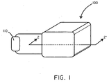
- FIG. 1 a perspective view of a battery assembly 100 in accordance with an embodiment of the invention is shown in conjunction with a load 110.
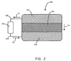
- FIG. 2 shows a cross-sectional schematic view of the battery assembly 100 as taken along line 2-2' of FIG. 1 .
- the battery assembly 100 includes an anode 102, a cathode 106, and a biosorbable separation element 104.
- the anode 102 can be comprised of a material that, when electrochemically oxidized, breaks down into reaction products that are substantially non-toxic. An extensive discussion of exemplary anode materials is included below. However, for purposes of a specific illustration, in some embodiments the anode 102 can be composed of magnesium. When the magnesium is electrochemically oxidized, magnesium ions are formed and then absorbed into the body.
- the cathode 106 can be comprised of a material that when electrochemically reduced breaks down into reaction products that are substantially non-toxic. An extensive discussion of exemplary cathode materials is included below. However, for purposes of a specific illustration, in some embodiments, the cathode 106 can be composed of manganese (IV) oxide. When the manganese (IV) oxide is electrochemically reduced, manganese (III) oxide is formed, which may be further reduced to manganese (II) hydroxide and then absorbed by the body.
- the anode 102 is separated from the cathode 106 by the biosorbable separation element 104.
- the biosorbable separation element 104 in some embodiments, can function to electrically insulate the anode 102 from the cathode 106, so that the electrochemical cell can be made to drive a load 110.
- the biosorbable separation element 104 can include electrolytes so as to allow the flow of ions and maintain charge balance during the electrochemical reaction.
- the biosorbable separation element 104 can include a polymeric matrix.
- the polymeric matrix itself can include electrolytes.
- an electrolyte composition can be disposed within the polymeric matrix.
- non-toxic electrolyte salts such as MgCl 2 or NaCl can be disposed within the polymeric matrix.
- the electrolyte composition can be inserted into the polymeric matrix during manufacturing of the battery assembly 100.
- the electrolyte composition such as a solution including sodium chloride for example, can diffuse into the polymeric matrix after implantation of the battery assembly 100.
- the battery 100 when the battery 100 is activated, such as in various ways described below, it can generate a current to be delivered to a load 110. Specifically, electrons can flow from the anode 102 in the direction of arrow 111 through a first conductor 108. The electrons can then pass through the load 110, through a second conductor 109 in the direction of arrow 112, before completing the circuit at the cathode 106. In order to maintain charge balance, positively charged ions can move in the direction of arrow 114, from the anode 102, through the biosorbable separation element 104 or in some cases around the biosorbable separation element 104, and to the cathode 106.
- the anode 102 will dissolve as the anode material is electrochemically oxidized.
- the anode material is magnesium
- the anode 102 will be broken down according to the following half-cell reaction: Mg ⁇ Mg 2 + + 2 e ⁇
- the cathode 106 is manganese (IV) oxide
- the corresponding half-cell reaction at the cathode is described by the following half-cell reaction: 2 MnO 2 + H 2 O + 2 e ⁇ ⁇ Mn 2 O 3 + 2 OH ⁇
- the electrochemical reaction would have a standard potential ( E 0 ) of over 2.8 V, while operating voltages of about 1.6 V are realized, indicating that the reaction is spontaneous.
- a soluble species in this case Mg 2+
- manganese (III) oxide forms at the cathode 106, which can be further reduced to manganese (II) hydroxide and then dissolve in the extracellular fluid of the body.
- the anode 102 and cathode 106 erode during operation of the battery and in the process a current is generated, until the anode 102 and/or the cathode 106 is completely dissolved, or until the circuit is otherwise opened.
- electrochemical reduction at the cathode 106 forms a chemical species that, while not highly soluble in the aqueous in vivo environment, nonetheless subsequently breaks down chemically and dissolves after the battery 100 is no longer operational. As such, even in these circumstances, the components of the battery are absorbed by the body.
- components such as the first conductor 108 and the second conductor 109 can be made of a material that is more noble (degrades less rapidly) than the anode 102, so that it will continue to function until the anode 102 is dissipated, but it will then itself degrade.
- the anode 102 is magnesium
- the first conductor 108 and the second conductor 109 can be made of aluminum or iron.
- FIGS. 1 and 2 illustrate the use of a single cell
- embodiments herein include batteries with a plurality of cells.
- a plurality of anode plates, cathodes plates, and biosorbable separation elements can be used in order to create a battery with a plurality of cells.
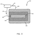
- the battery assembly 200 includes an anode 202, a cathode 206, and a biosorbable separation element 204.
- the anode 202, cathode 206, and biosorbable separation element 204 can be composed of various materials as described more fully below.
- the battery assembly 200 can further include a first conductor 208 and a second conductor 209, to carry electrons in the direction of arrows 211 and 212 respectively.
- the battery assembly 200 can be connected to a load 210.
- the biosorbable separation element 204 can surround the cathode 206, with the anode 202 disposed around the outside of the biosorbable separation element.
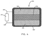
- battery assemblies in accordance with embodiments herein can include biosorbable coatings disposed on the outside of the battery assembly that degrade after the battery assembly is inserted in vivo.
- the battery assembly can be coated with a biosorbable polymer layer. It is believed that this configuration can be advantageous to protect the battery assembly during the handling steps that may occur prior to implantation and also to increase the structural integrity of the battery assembly.
- the battery assembly 300 can include an anode 302, a biosorbable separator 304, and a cathode 306.
- the battery assembly 300 can further include a first conductor 308, and a second conductor 309.
- the battery assembly 300 can be in electrical communication with a load 310.
- the battery assembly 300 can further include a biosorbable coating 320, disposed around the outside of the battery assembly 300.
- the biosorbable coating 320 can be composed of various materials such as biosorbable polymers, carbohydrates, and the like.
- Biosorbable polymers can include those having hydrolytically labile chemical bonds or bonds that are otherwise subject to enzymatic cleavage.
- biosorbable polymers can include those having ester, anhydride, or amide bonds in the polymeric backbone.
- Specific biosorbable polymers can include polylactide (PLA), polyglycolide (PGA), polycaprolactone (PCL), poly(saccharide)s, poly(ethylene oxide), poly(ethylene glycol), copolymers thereof, and the like.
- the biosorbable separation element simply provides electrical insulation between the anode and the cathode.
- the biosorbable separation element also provides a conduit for the passage of ions between the anode and the cathode. That is, the battery assembly can be constructed so that the movement of ions needed to maintain charge balance during operation of the battery assembly occurs through the biosorbable separation element, occurs outside of the biosorbable separation element, or occurs through both pathways.
- the battery assembly 400 can include an anode 402, a biosorbable separator 404, a cathode 406, and an ion transfer conduit 412.
- the ion transfer conduit 412 can be configured to allow for the transfer of ions between the anode 402 and the cathode 406.
- the ion transfer conduit 412 can include an electrolyte.
- the ion transfer conduit 412 can include a porous degradable material, such as a polymer, that can include an electrolyte for purposes of conveying ions.
- the battery assembly 400 can further include a first conductor 408, and a second conductor 410.
- the tissue of the body itself can be utilized for the purpose of transferring ions between the anode and the cathode.
- the extracellular fluid in vivo is an aqueous solution that includes at least some amount of electrolytes such as sodium and potassium. Therefore, extracellular fluid can be used to transfer ions between the anode and the cathode in some embodiments.
- an electrochemical oxidation reaction takes place at the anode liberating electrons that can then be used to drive a load.
- the anode material can be selected so that the reaction products of the electrochemical oxidation are substantially non-toxic. In this manner, the reaction products at the anode can simply be absorbed by the body.
- the anode can be made of many different materials.
- the anode can be made of various metals, various alloys of metals, compounds including metal atoms, ceramic/metal composite and various polymers.
- Exemplary metals can include calcium, magnesium, iron, bismuth, zinc, and aluminum.
- the anode can specifically include magnesium, magnesium alloys, iron, and iron alloys. While not intending to be bound by theory, magnesium and iron can be advantageous as they are both required nutrients and are very safe at the concentrations that would be likely to be achieved by embodiments as disclosed herein.
- Exemplary polymers can include electrochemically oxidizable degradable polymers, such as various types of organometallic polymers.
- anode materials can include PPy based positive electrode array, carbon MEMS, FeOx-C nanofibers, (LiTi 2 (PO 4 ) 3 ), ZnO with conductive ceramics such as Mg(OH) 2 and Ca(OH) 2 nanocomposites, CoFe 2 O 4 .
- Cathode materials used with embodiments herein can be selected so that electrochemical reduction of the cathode material results in reaction products that are substantially non-toxic.
- the cathode material can include materials such as metal oxides, metal hydroxides, metal oxyhydroxides, polyoxymetallates, metal salts, electrochemically reducible organic compounds, and electrochemically reducible biosorbable polymers.
- Exemplary metal oxides can include Mn 2 O 3 , MnO 2 , and Fe 2 O 3 . Further examples of metal oxides can include Bi 2 O 3 and Bi 2 O 4 .
- Exemplary metal oxyhydroxides can include MnOOH.
- Exemplary metal salts can include metal halides, metal sulfides, metal sulfates, and/or metal phosphates.
- Exemplary metal halides can include FeCl 3 and the like.
- metal sulfides can include FeS 2 , Bi 2 S 3 , and the like.
- Exemplary metal sulfates can include FeSO 4 and MnSO 4 .
- Exemplary metal phosphates can include FePO 4 and MnPO 4 .
- Exemplary electrochemically reducible organic compounds can include electrochemically active biological compounds, including metalloenzymes and metalloproteins like oxidases, peroxidases, catalases, superoxide dismutases, and derivatives of the same. Specific examples may include ferredoxins and cytochrome c oxidase.
- Exemplary electrochemically reducible organic compounds can further include metal ion containing macrocycle compounds, including, but not limited to, porphyrins, phthalocyanines and tetraazamacrocycles.
- Exemplary electrochemically reducible biosorbable polymers can include nontoxic conjugated or nonconjugated polymeric disulfide compounds, conjugated or nonconjugated metallopolymers based on nontoxic metal ion complexes, such as ferrocene (including polyvinylferrocene), Schiff bases or heterocycle metal ion complexes, including, but not limited to, polymeric metal ion heterocycles and metal containing macrocycle compounds like porphyrins, phthalocyanines and tetraazamacrocycles.
- Exemplary electrochemically reducible biosorbable polymers can also include conjugated organic polymers like polypyrroles, polythiophenes and polyanilines.
- Exemplary electrochemically reducible biosorbable polymers can also include polymers or copolymers including biosorbable polymer units like polyethylene oxide, polylactide, polycaprolactone or their copolymers.
- cathode materials can include NaFeOx or KFeMnOx; calcium zincate; ZnMnOx; Birnessite type MnOx; iron-manganese phosphate composites; Na or K CoMnCaOx; various organic radical materials; olivine; spherical spinel or spinels in general; PPy/maghemite; and sulfur and oxide based (dual active material composite cathode).
- the cathode material can be a material configured to intercalate ions produced during electrochemical oxidation of the anode.
- the cathode material can be selected to be a material that can intercalate magnesium ions.
- the cathode material can be a material configured to intercalate other ions, such as sodium and/or hydrogen ions.
- Cathode materials used with embodiment herein can be selected so that the cathode material has a higher oxidation potential than the material of the anode. Stated differently, the cathode material can be selected so that is has a larger standard reduction potential than the material of the anode.
- anode and cathode materials include, but are not limited to, those described in Table 1 below.
- Anode Materials Cathode Materials Mg MnOOH Mg FePO 4 Mg Ferredoxin Mg Polyethylenedisulfide Fe FeOOH
- Various embodiments included herein can include a separation element in order to separate the anode from the cathode.
- the separation element can be biosorbable in that it can be made of materials that can harmlessly be absorbed by the body, or break-down into chemical species that can harmlessly be absorbed by the body.
- the biosorbable separation element can be made of biosorbable polymers, biosorbable carbohydrates, and the like.
- Biosorbable polymers can include those having hydrolytically labile chemical bonds or bonds that are otherwise subject to enzymatic cleavage.
- biosorbable polymers can include those having ester, anhydride, or amide bonds in the polymeric backbone.
- Specific biosorbable polymers can include polylactide (PLA), polyglycolide (PGA), polycaprolactone (PCL), poly(saccharide)s, poly(ethylene oxide), poly(ethylene glycol), copolymers thereof, and the like.
- PLA polylactide
- PGA polyglycolide
- PCL polycaprolactone
- the biosorbable separation element can include a porous polymeric matrix.
- the porous polymeric matrix can include a biosorbable polymer, such as those described above.
- an electrolyte composition can be disposed within the porous polymeric matrix.
- a solution such as a sodium chloride solution, a magnesium chloride solution, or a potassium chloride solution can be disposed within the porous polymeric matrix.
- the electrolyte composition can be put within the porous polymeric matrix at the time of manufacturing the battery assembly.
- the biosorbable separation element can include a compound that renders the component radio-opaque.
- the material of the biosorbable separation element can include an x-ray absorbing moiety such as iodine, rendering the biosorbable separation element radio-opaque.
- the battery can be activated through a switching mechanism. That is, a circuit can be closed so that the flow of current is initiated.
- the battery can be activated by diffusion of water and/or electrolytes from the extracellular fluid surrounding the battery structure and into components of the battery assembly.
- water and/or electrolytes from the extracellular fluid surrounding the battery can diffuse into the separation element, thus creating a pathway for the migration of ions needed to operate the battery.
- metal salts such as sodium chloride and the like can be disposed within the porous polymeric matrix, but not in solution, such that the electrolyte is not be immediately active for purposes of transport of ions.
- the battery assembly can be constructed so that water that contacts the outside of the battery assembly, such as after implantation, can diffuse into the porous polymeric matrix, thereby effectively activating the transport of ions.
- battery devices as described herein can be used in conjunction with many different types of implantable medical devices. Specifically, battery devices as described herein can be used with any type of implantable medical device that requires a power source. Battery devices as described herein can be used in conjunction with both temporary and chronically implanted medical devices.
- the invention includes a biosorbable battery in electrical communication with an implantable medical device. Exemplary medical devices can include both biosorbable and non-biosorbable medical devices.
- Exemplary medical devices can include, but are not limited to, implantable cardiac rhythm management devices (including pacemakers, cardiac resynchronization therapy (CRT) devices, remodeling control therapy (RCT) device, cardioverter/defibrillators, or pacemaker-cardioverter/defibrillators, and the like), neurological stimulators, implantable sensors, and the like.
- implantable cardiac rhythm management devices including pacemakers, cardiac resynchronization therapy (CRT) devices, remodeling control therapy (RCT) device, cardioverter/defibrillators, or pacemaker-cardioverter/defibrillators, and the like
- CTR cardiac resynchronization therapy
- RCT remodeling control therapy
- cardioverter/defibrillators or pacemaker-cardioverter/defibrillators, and the like
- neurological stimulators implantable sensors, and the like.
- implantable cardiac rhythm management devices including pacemakers, cardiac resynchronization therapy (CRT) devices, remodeling control therapy (RCT) device, cardioverter/defibrillators, or
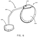
- the medical device system 600 includes an implanted medical device 610 and a biosorbable battery 606.
- a connection lead 608 provided electrical communication between the implanted medical device 610 and the biosorbable battery 606.
- the implanted medical device 610 can include a header 602 and a hermetically scaled case 604.
- Various electrical components including control circuitry are disposed within the case 604.
- the medical device system 600 can also include one or more electrical stimulation leads including electrodes in order to convey electrical stimulation pulses to tissues of the body.
- the phrase “configured” describes a system, apparatus, or other structure that is constructed or configured to perform a particular task or adopt a particular configuration.
- the phrase “configured” can be used interchangeably with other similar phrases such as “arranged”, “arranged and configured”, “constructed and arranged”, “constructed”, “manufactured and arranged”, and the like.
Description
- This disclosure relates generally to batteries and, more particularly, to batteries that are biosorbable when implanted in a subject, amongst other things.
- Many types of medical devices are designed to be implanted within the human body. Examples include stents, scaffolds, drug delivery devices, cardiac rhythm management devices, neurological stimulation devices, and the like. Some implantable medical devices are designed to function by utilizing energy from a power source. Frequently, such devices include a battery, which is implanted into the body as part of the medical device and is typically housed within a sealed case. In many circumstances, the sealed case is made from a relatively noble metal such as titanium to prevent the exposure of the contents of the battery to the in vivo environment. In the absence of recharging, batteries can only provide a finite amount of power before they are discharged to the point of being useless. In circumstances where a battery has been completely discharged, the battery and the associated medical device must generally be explanted and replaced by a new one, unless the battery was only intended for temporary use. For example, when the battery inside a pacemaker no longer provides sufficient power, the pacemaker must generally be surgically removed and replaced with a new pacemaker.
- Unfortunately, removal of implanted devices is not always an easy task. The body's immunological response to a foreign body generally results over time in the formation of fibrous tissue around an implanted medical device. This fibrous tissue can make it difficult to remove implanted medical devices without risking harm to the patient.
- Published
U.S. patent application no. 2006/0093923 A1 discloses a medical device including a rechargeable lithium-ion battery for providing power to the medical device. The lithium-ion battery includes a positive electrode including a current collector, a first active material, and a second active material. The lithium-ion battery also includes a negative electrode including a current collector, a third active material, and a quantity of lithium in electrical contact with the current collector of the negative electrode. The second active material exhibits charging and discharging capacity below a corrosion potential of the current collector of the negative electrode and above a decomposition potential of the first active material. - The present invention relates to a medical device system as set out in claim 1 and a method of making a biosorbable battery as set out in claim 11. Other embodiments are described in the dependent claims.
- A system according to the first part of claim 1 is knwon from
U.S. patent no. 3 842 843 . - This summary is an overview of some of the teachings of the present application and is not intended to be an exclusive or exhaustive treatment of the present subject matter. Further details are found in the detailed description and appended claims. Other aspects will be apparent to persons skilled in the art upon reading and understanding the following detailed description and viewing the drawings that form a part thereof, each of which is not to be taken in a limiting sense. The scope of the present invention is defined by the appended claims.
- The invention may be more completely understood in connection with the following drawings, in which:
-
FIG. 1 is a perspective view of a battery assembly in accordance with an embodiment. -
FIG. 2 is a schematic cross-sectional view of a battery assembly as taken along line 2-2' ofFIG. 1 . -
FIG. 3 is a schematic cross-sectional view of a battery assembly in accordance with another embodiment.FIG. 4 is a schematic cross-sectional view of a battery assembly in accordance with another embodiment. -
FIG. 5 is a schematic cross-sectional view of a battery assembly in accordance with another embodiment. -
FIG. 6 is a schematic view of a medical device system in accordance with an embodiment. - While the invention is susceptible to various modifications and alternative forms, specifics thereof have been shown by way of example and drawings, and will be described in detail. It should be understood, however, that the invention is not limited to the particular embodiments described. On the contrary, the intention is to cover modifications, equivalents, and alternatives falling within the spirit and scope of the invention.
- Challenges associated with removing components of an implanted medical device can be obviated by making the implanted device biosorbable. However, in the context of implanted medical devices that require a power source, an additional challenge is presented because existing batteries generally include components that are not biosorbable.
- As described herein, embodiments of the present invention include battery assemblies that are biosorbable. Specifically, embodiments herein include batteries with biosorbable components that can harmlessly disintegrate after a period of time within the body. In an embodiment, the invention includes a biosorbable battery assembly including an anode, a cathode, and a biosorbable separation element. The anode can be constructed of a material such that electrochemical oxidation results in the formation of reaction products that are substantially non-toxic. Similarly, the cathode can be constructed of a material such that electrochemical reduction results in the formation of reaction products that are substantially non-toxic. In order to generate a current, the cathode material has a larger standard reduction potential than the material of the anode. Finally, the biosorbable separation element can be disposed between the anode and the cathode. In some embodiments, the biosorbable separation element can be configured to provide electrical insulation between the anode and the cathode, yet permit an electrochemical reaction to occur involving the transfer of ions between the anode and the cathode.
- As used herein the term "biosorbable" in reference to a material shall refer to the property of the material being able to be harmlessly absorbed by the body.
- As used herein the term "substantially non-toxic" in reference to a chemical compound shall refer to the property of the chemical compound being unlikely to cause harm to an individual at dosages that are reasonably forseeable given the manner in which the chemical compound is being used and/or produced.
- Referring now to
FIG. 1 , a perspective view of abattery assembly 100 in accordance with an embodiment of the invention is shown in conjunction with aload 110.FIG. 2 shows a cross-sectional schematic view of thebattery assembly 100 as taken along line 2-2' ofFIG. 1 . Thebattery assembly 100 includes ananode 102, acathode 106, and abiosorbable separation element 104. Theanode 102 can be comprised of a material that, when electrochemically oxidized, breaks down into reaction products that are substantially non-toxic. An extensive discussion of exemplary anode materials is included below. However, for purposes of a specific illustration, in some embodiments theanode 102 can be composed of magnesium. When the magnesium is electrochemically oxidized, magnesium ions are formed and then absorbed into the body. - The
cathode 106 can be comprised of a material that when electrochemically reduced breaks down into reaction products that are substantially non-toxic. An extensive discussion of exemplary cathode materials is included below. However, for purposes of a specific illustration, in some embodiments, thecathode 106 can be composed of manganese (IV) oxide. When the manganese (IV) oxide is electrochemically reduced, manganese (III) oxide is formed, which may be further reduced to manganese (II) hydroxide and then absorbed by the body. - The
anode 102 is separated from thecathode 106 by thebiosorbable separation element 104. Thebiosorbable separation element 104, in some embodiments, can function to electrically insulate theanode 102 from thecathode 106, so that the electrochemical cell can be made to drive aload 110. In many embodiments, thebiosorbable separation element 104 can include electrolytes so as to allow the flow of ions and maintain charge balance during the electrochemical reaction. In some embodiments thebiosorbable separation element 104 can include a polymeric matrix. In some embodiments, the polymeric matrix itself can include electrolytes. In some embodiments, an electrolyte composition can be disposed within the polymeric matrix. For example, non-toxic electrolyte salts such as MgCl2 or NaCl can be disposed within the polymeric matrix. In some embodiments, the electrolyte composition can be inserted into the polymeric matrix during manufacturing of thebattery assembly 100. In other embodiments, the electrolyte composition, such as a solution including sodium chloride for example, can diffuse into the polymeric matrix after implantation of thebattery assembly 100. - In operation, when the
battery 100 is activated, such as in various ways described below, it can generate a current to be delivered to aload 110. Specifically, electrons can flow from theanode 102 in the direction of arrow 111 through afirst conductor 108. The electrons can then pass through theload 110, through asecond conductor 109 in the direction ofarrow 112, before completing the circuit at thecathode 106. In order to maintain charge balance, positively charged ions can move in the direction ofarrow 114, from theanode 102, through thebiosorbable separation element 104 or in some cases around thebiosorbable separation element 104, and to thecathode 106. - During the discharging process, the
anode 102 will dissolve as the anode material is electrochemically oxidized. For example, where the anode material is magnesium, theanode 102 will be broken down according to the following half-cell reaction:
- Where the
cathode 106 is manganese (IV) oxide, as a specific example, the corresponding half-cell reaction at the cathode is described by the following half-cell reaction:
- Pairing these two half-cells, the electrochemical reaction would have a standard potential (E 0) of over 2.8 V, while operating voltages of about 1.6 V are realized, indicating that the reaction is spontaneous.
- As the
anode 102 reacts, a soluble species (in this case Mg2+) is formed at theanode 102 which simply dissolves into the extracellular fluid of the body. Similarly, in this case, manganese (III) oxide forms at thecathode 106, which can be further reduced to manganese (II) hydroxide and then dissolve in the extracellular fluid of the body. As such, theanode 102 andcathode 106 erode during operation of the battery and in the process a current is generated, until theanode 102 and/or thecathode 106 is completely dissolved, or until the circuit is otherwise opened. - In some embodiments, electrochemical reduction at the
cathode 106 forms a chemical species that, while not highly soluble in the aqueous in vivo environment, nonetheless subsequently breaks down chemically and dissolves after thebattery 100 is no longer operational. As such, even in these circumstances, the components of the battery are absorbed by the body. - After the
battery 100 ceases operation, whatever remaining elements that are present will degrade, for example thefirst conductor 108, thesecond conductor 109, and/or thebiosorbable separator 104, will degrade, eventually being totally absorbed by the body. In some embodiments, components such as thefirst conductor 108 and thesecond conductor 109 can be made of a material that is more noble (degrades less rapidly) than theanode 102, so that it will continue to function until theanode 102 is dissipated, but it will then itself degrade. By way of example, in some embodiments where theanode 102 is magnesium, thefirst conductor 108 and thesecond conductor 109 can be made of aluminum or iron. - It will be appreciated that there are many different half-cell reactions which can be utilized in order to create a battery assembly consistent with embodiments herein, wherein the standard reduction potential of the anode material is less than the standard reduction potential of the cathode material and the reactions at both the anode and cathode generate reaction products that are substantially non-toxic. Specific examples of anode and cathode materials are described in greater detail below.
- While the battery of
FIGS. 1 and2 illustrate the use of a single cell, it will be appreciated that embodiments herein include batteries with a plurality of cells. By way of example, in some embodiments, a plurality of anode plates, cathodes plates, and biosorbable separation elements can be used in order to create a battery with a plurality of cells. - Battery assemblies, in accordance with embodiments herein, can take on various physical configurations. By way of example, referring now to
FIG. 3 , a schematic cross-sectional view of a battery in accordance with another embodiment is shown. In this embodiment, thebattery assembly 200 includes ananode 202, acathode 206, and abiosorbable separation element 204. Theanode 202,cathode 206, andbiosorbable separation element 204 can be composed of various materials as described more fully below. Thebattery assembly 200 can further include afirst conductor 208 and asecond conductor 209, to carry electrons in the direction ofarrows battery assembly 200 can be connected to aload 210. In this embodiment, thebiosorbable separation element 204 can surround thecathode 206, with theanode 202 disposed around the outside of the biosorbable separation element. - In some embodiments, battery assemblies in accordance with embodiments herein can include biosorbable coatings disposed on the outside of the battery assembly that degrade after the battery assembly is inserted in vivo. By way of example, the battery assembly can be coated with a biosorbable polymer layer. It is believed that this configuration can be advantageous to protect the battery assembly during the handling steps that may occur prior to implantation and also to increase the structural integrity of the battery assembly. As a specific example, referring now to
FIG. 4 , thebattery assembly 300 can include ananode 302, abiosorbable separator 304, and acathode 306. Thebattery assembly 300 can further include afirst conductor 308, and asecond conductor 309. Thebattery assembly 300 can be in electrical communication with aload 310. Thebattery assembly 300 can further include abiosorbable coating 320, disposed around the outside of thebattery assembly 300. - The
biosorbable coating 320 can be composed of various materials such as biosorbable polymers, carbohydrates, and the like. Biosorbable polymers can include those having hydrolytically labile chemical bonds or bonds that are otherwise subject to enzymatic cleavage. For example, biosorbable polymers can include those having ester, anhydride, or amide bonds in the polymeric backbone. Specific biosorbable polymers can include polylactide (PLA), polyglycolide (PGA), polycaprolactone (PCL), poly(saccharide)s, poly(ethylene oxide), poly(ethylene glycol), copolymers thereof, and the like. - In some embodiments, the biosorbable separation element simply provides electrical insulation between the anode and the cathode. In other embodiments, the biosorbable separation element also provides a conduit for the passage of ions between the anode and the cathode. That is, the battery assembly can be constructed so that the movement of ions needed to maintain charge balance during operation of the battery assembly occurs through the biosorbable separation element, occurs outside of the biosorbable separation element, or occurs through both pathways.
- Referring now to
FIG. 5 , a schematic view is shown of a battery assembly wherein the flow of ions occurs through an element other than the biosorbable separator. Thebattery assembly 400 can include ananode 402, abiosorbable separator 404, acathode 406, and anion transfer conduit 412. In this embodiment, theion transfer conduit 412 can be configured to allow for the transfer of ions between theanode 402 and thecathode 406. Specifically, theion transfer conduit 412 can include an electrolyte. In some embodiments, theion transfer conduit 412 can include a porous degradable material, such as a polymer, that can include an electrolyte for purposes of conveying ions. Thebattery assembly 400 can further include afirst conductor 408, and asecond conductor 410. - It will be appreciated that in some embodiments the tissue of the body itself can be utilized for the purpose of transferring ions between the anode and the cathode. For example, the extracellular fluid in vivo is an aqueous solution that includes at least some amount of electrolytes such as sodium and potassium. Therefore, extracellular fluid can be used to transfer ions between the anode and the cathode in some embodiments.
- As described above, in operation an electrochemical oxidation reaction takes place at the anode liberating electrons that can then be used to drive a load. The anode material can be selected so that the reaction products of the electrochemical oxidation are substantially non-toxic. In this manner, the reaction products at the anode can simply be absorbed by the body.
- It will be appreciated that the anode can be made of many different materials. By way of example, the anode can be made of various metals, various alloys of metals, compounds including metal atoms, ceramic/metal composite and various polymers. Exemplary metals can include calcium, magnesium, iron, bismuth, zinc, and aluminum. In some embodiments, the anode can specifically include magnesium, magnesium alloys, iron, and iron alloys. While not intending to be bound by theory, magnesium and iron can be advantageous as they are both required nutrients and are very safe at the concentrations that would be likely to be achieved by embodiments as disclosed herein. Exemplary polymers can include electrochemically oxidizable degradable polymers, such as various types of organometallic polymers. Other anode materials can include PPy based positive electrode array, carbon MEMS, FeOx-C nanofibers, (LiTi2(PO4)3), ZnO with conductive ceramics such as Mg(OH)2 and Ca(OH)2 nanocomposites, CoFe2O4.
- Cathode materials used with embodiments herein can be selected so that electrochemical reduction of the cathode material results in reaction products that are substantially non-toxic.
- In some embodiments, the cathode material can include materials such as metal oxides, metal hydroxides, metal oxyhydroxides, polyoxymetallates, metal salts, electrochemically reducible organic compounds, and electrochemically reducible biosorbable polymers. Exemplary metal oxides can include Mn2O3, MnO2, and Fe2O3. Further examples of metal oxides can include Bi2O3 and Bi2O4. Exemplary metal oxyhydroxides can include MnOOH. Exemplary metal salts can include metal halides, metal sulfides, metal sulfates, and/or metal phosphates. Exemplary metal halides can include FeCl3 and the like. For example, metal sulfides can include FeS2, Bi2S3, and the like. Exemplary metal sulfates can include FeSO4 and MnSO4. Exemplary metal phosphates can include FePO4 and MnPO4. Exemplary electrochemically reducible organic compounds can include electrochemically active biological compounds, including metalloenzymes and metalloproteins like oxidases, peroxidases, catalases, superoxide dismutases, and derivatives of the same. Specific examples may include ferredoxins and cytochrome c oxidase. Exemplary electrochemically reducible organic compounds can further include metal ion containing macrocycle compounds, including, but not limited to, porphyrins, phthalocyanines and tetraazamacrocycles. Exemplary electrochemically reducible biosorbable polymers can include nontoxic conjugated or nonconjugated polymeric disulfide compounds, conjugated or nonconjugated metallopolymers based on nontoxic metal ion complexes, such as ferrocene (including polyvinylferrocene), Schiff bases or heterocycle metal ion complexes, including, but not limited to, polymeric metal ion heterocycles and metal containing macrocycle compounds like porphyrins, phthalocyanines and tetraazamacrocycles. Exemplary electrochemically reducible biosorbable polymers can also include conjugated organic polymers like polypyrroles, polythiophenes and polyanilines. Exemplary electrochemically reducible biosorbable polymers can also include polymers or copolymers including biosorbable polymer units like polyethylene oxide, polylactide, polycaprolactone or their copolymers. Other cathode materials can include NaFeOx or KFeMnOx; calcium zincate; ZnMnOx; Birnessite type MnOx; iron-manganese phosphate composites; Na or K CoMnCaOx; various organic radical materials; olivine; spherical spinel or spinels in general; PPy/maghemite; and sulfur and oxide based (dual active material composite cathode).
- In some embodiments, the cathode material can be a material configured to intercalate ions produced during electrochemical oxidation of the anode. For example, if electrochemical oxidation of the anode material results in the formation of magnesium ions, the cathode material can be selected to be a material that can intercalate magnesium ions. In some embodiments, the cathode material can be a material configured to intercalate other ions, such as sodium and/or hydrogen ions.
- Cathode materials used with embodiment herein can be selected so that the cathode material has a higher oxidation potential than the material of the anode. Stated differently, the cathode material can be selected so that is has a larger standard reduction potential than the material of the anode.
- Specific pairings of anode and cathode materials include, but are not limited to, those described in Table 1 below.
TABLE 1 Anode Materials Cathode Materials Mg MnOOH Mg FePO4 Mg Ferredoxin Mg Polyethylenedisulfide Fe FeOOH - Various embodiments included herein can include a separation element in order to separate the anode from the cathode. The separation element can be biosorbable in that it can be made of materials that can harmlessly be absorbed by the body, or break-down into chemical species that can harmlessly be absorbed by the body.
- It will be appreciated that many different materials can be used in order to create a biosorbable separation element. By way of example, the biosorbable separation element can be made of biosorbable polymers, biosorbable carbohydrates, and the like. Biosorbable polymers can include those having hydrolytically labile chemical bonds or bonds that are otherwise subject to enzymatic cleavage. For example, biosorbable polymers can include those having ester, anhydride, or amide bonds in the polymeric backbone. Specific biosorbable polymers can include polylactide (PLA), polyglycolide (PGA), polycaprolactone (PCL), poly(saccharide)s, poly(ethylene oxide), poly(ethylene glycol), copolymers thereof, and the like. However, it will be appreciated that there are also other biosorbable polymers that can be used and are included within the scope of what is contemplated herein.
- In some embodiments, the biosorbable separation element can include a porous polymeric matrix. The porous polymeric matrix can include a biosorbable polymer, such as those described above. In some embodiments, an electrolyte composition can be disposed within the porous polymeric matrix. By way of example, a solution such as a sodium chloride solution, a magnesium chloride solution, or a potassium chloride solution can be disposed within the porous polymeric matrix. In some embodiments, the electrolyte composition can be put within the porous polymeric matrix at the time of manufacturing the battery assembly.
- In some embodiments the biosorbable separation element can include a compound that renders the component radio-opaque. By way of example, in some embodiments, the material of the biosorbable separation element can include an x-ray absorbing moiety such as iodine, rendering the biosorbable separation element radio-opaque.
- It will be appreciated that there are various approaches to activating a battery assembly as described herein. By way of example, the battery can be activated through a switching mechanism. That is, a circuit can be closed so that the flow of current is initiated.
- In some embodiments, the battery can be activated by diffusion of water and/or electrolytes from the extracellular fluid surrounding the battery structure and into components of the battery assembly. For example, in some embodiments, water and/or electrolytes from the extracellular fluid surrounding the battery can diffuse into the separation element, thus creating a pathway for the migration of ions needed to operate the battery. Specifically, in some embodiments, metal salts such as sodium chloride and the like can be disposed within the porous polymeric matrix, but not in solution, such that the electrolyte is not be immediately active for purposes of transport of ions. In such a case, the battery assembly can be constructed so that water that contacts the outside of the battery assembly, such as after implantation, can diffuse into the porous polymeric matrix, thereby effectively activating the transport of ions.
- It will be appreciated that battery devices as described herein can be used in conjunction with many different types of implantable medical devices. Specifically, battery devices as described herein can be used with any type of implantable medical device that requires a power source. Battery devices as described herein can be used in conjunction with both temporary and chronically implanted medical devices. In some embodiments, the invention includes a biosorbable battery in electrical communication with an implantable medical device. Exemplary medical devices can include both biosorbable and non-biosorbable medical devices. Exemplary medical devices can include, but are not limited to, implantable cardiac rhythm management devices (including pacemakers, cardiac resynchronization therapy (CRT) devices, remodeling control therapy (RCT) device, cardioverter/defibrillators, or pacemaker-cardioverter/defibrillators, and the like), neurological stimulators, implantable sensors, and the like. One example of a cardiac rhythm management device is disclosed in commonly assigned
U.S. Pat. No. 4,562,841 . It will be appreciated that there are also many other examples contemplated. - Referring now to
FIG. 6 , a schematic view of amedical device system 600 is shown in accordance with an embodiment of the invention. Themedical device system 600 includes an implantedmedical device 610 and abiosorbable battery 606. Aconnection lead 608 provided electrical communication between the implantedmedical device 610 and thebiosorbable battery 606. In this embodiment, the implantedmedical device 610 can include aheader 602 and a hermetically scaledcase 604. Various electrical components including control circuitry are disposed within thecase 604. Though not shown in this view, it will be appreciated that themedical device system 600 can also include one or more electrical stimulation leads including electrodes in order to convey electrical stimulation pulses to tissues of the body. - It should be noted that, as used in this specification and the appended claims, the singular forms "a," "an," and "the" include plural referents unless the content clearly dictates otherwise. It should also be noted that the term "or" is generally employed in its sense including "and/or" unless the content clearly dictates otherwise.
- It should also be noted that, as used in this specification and the appended claims, the phrase "configured" describes a system, apparatus, or other structure that is constructed or configured to perform a particular task or adopt a particular configuration. The phrase "configured" can be used interchangeably with other similar phrases such as "arranged", "arranged and configured", "constructed and arranged", "constructed", "manufactured and arranged", and the like.
- All publications and patent applications in this specification are indicative of the level of ordinary skill in the art to which this invention pertains.
- This application is intended to cover adaptations or variations of the present subject matter. It is to be understood that the above description is intended to be illustrative, and not restrictive. The scope of the present subject matter should be determined with reference to the appended claims.
Claims (14)
- A medical device system (600) comprising:an implantable medical device (610); and characterized by:a biosorbable battery assembly (606) in electrical communication with the implanted medical device (610); the biosorbable battery assembly (606) comprisingan anode (102) comprising an anode material, wherein electrochemical oxi-dation of the anode material results in the formation of reaction products that are substantially non-toxic;a cathode (106) comprising a cathode material, wherein electrochemical re-duction of the cathode material results in the formation of reaction products that are substantially non-toxic, the cathode material having a larger standard reduction potential than the anode material; and characterized by:a biosorbable separation element (104) disposed between the anode (102) and the cathode (106), configured to provide electrical insulation between the anode (102) and the cathode (106).
- The medical device system of claim 1, the anode material comprising a material selected from the group consisting of magnesium, magnesium alloys, iron, iron alloys, zinc, zinc alloys, aluminum, aluminum alloys, and electrochemically oxidizable degradable polymers or selected from the group consisting of magnesium, magnesium alloys, iron, and iron alloys.
- The medical device system of claim 1, the cathode material comprising a material selected from the group of materials consisting of metal oxides, metal hydroxides, metal oxyhydroxides, polyoxymetallates, metal salts, and electrochemically reducible degradable polymers or selected from the group consisting of MnOOH, Mn2O3, MnO2, and Fe2O3.
- The medical device system of claim 3, the metal salts comprising metal halides, metal sulfides, metal sulfates, and/or metal phosphates
- The medical device system of claim 1, the cathode material comprising a material configured to intercalate metal ions produced during electrochemical oxidation of the anode (102) or a material configured to intercalate magnesium, sodium, and/or hydrogen ions.
- The medical device system of claim 1, the biosorbable separation element (104) comprising a polymeric matrix or comprising an electrolyte solution.
- The medical device system of claim 6, the polymeric matrix comprising a polymer selected from the group consisting of polyethylene oxide, polylactide, polycaprolactone, and co-polymers thereof.
- The medical device system of claim 1, the biosorbable separation element (104) configured to permit the transfer of ions there through, between the anode (102) and the cathode (106).
- The medical device system of claim 1, further comprising a conductor (108) in electrical communication with the anode (102) or in electrical communication with the cathode (106), the conductor (108) comprising a conductive material more noble than the material of the anode (102).
- The medical device system (600) of claim 1, the implantable medical device (610) comprising a cardiac rhythm management device.
- A method of making a medical device system (600), the method comprising providing an implantable medical device (610) and a biosorbable battery (606), the biosorable battery being made coupling an anode (102) to a biosorbable separation element (104); the anode (102) comprising a first material, wherein electrochemical oxidation of the first material results in the formation of reaction products that are substantially non-toxic; the biosorbable separation element (104) comprising a biosorbable material; and coupling a cathode (106) to the biosorbable separation element (104), the cathode (106) comprising a second material, wherein electrochemical reduction of the second material results in the formation of reaction products that are substantially non-toxic, the second material having a larger standard reduction potential than the first material.
- The method of claim 11, further comprising disposing a biosorbable coating over the anode (102), the biosorbable separation element (104) and the cathode (106).
- The method of claim 11, the biosorbable separation element (104) comprising a biosorbable polymer.
- The method of claim 11, further comprising coupling a first conductor (108) to the anode (102) and a second conductor (109) to the cathode (106).
Applications Claiming Priority (2)
| Application Number | Priority Date | Filing Date | Title |
|---|---|---|---|
| US10259808P | 2008-10-03 | 2008-10-03 | |
| PCT/US2009/059397 WO2010040065A1 (en) | 2008-10-03 | 2009-10-02 | Biosorbable battery and related methods |
Publications (2)
| Publication Number | Publication Date |
|---|---|
| EP2349472A1 EP2349472A1 (en) | 2011-08-03 |
| EP2349472B1 true EP2349472B1 (en) | 2016-03-30 |
Family
ID=41353972
Family Applications (1)
| Application Number | Title | Priority Date | Filing Date |
|---|---|---|---|
| EP09793282.6A Not-in-force EP2349472B1 (en) | 2008-10-03 | 2009-10-02 | Biosorbable battery and related methods |
Country Status (4)
| Country | Link |
|---|---|
| US (1) | US8761877B2 (en) |
| EP (1) | EP2349472B1 (en) |
| JP (1) | JP5357259B2 (en) |
| WO (1) | WO2010040065A1 (en) |
Families Citing this family (14)
| Publication number | Priority date | Publication date | Assignee | Title |
|---|---|---|---|---|
| US8761877B2 (en) | 2008-10-03 | 2014-06-24 | Cardiac Pacemakers, Inc. | Biosorbable battery and related methods |
| US8968926B2 (en) * | 2011-07-15 | 2015-03-03 | Covidien Lp | Degradable implantable galvanic power source |
| US8968927B2 (en) * | 2011-07-15 | 2015-03-03 | Covidien Lp | Degradable implantable battery |
| JP5596726B2 (en) * | 2012-03-05 | 2014-09-24 | 日本電信電話株式会社 | Magnesium battery |
| JP5627031B2 (en) * | 2012-03-13 | 2014-11-19 | 日本電信電話株式会社 | Magnesium battery |
| US9985320B2 (en) | 2012-04-30 | 2018-05-29 | Carnegie Mellon University | Water-activated, ingestible battery |
| WO2015061537A1 (en) * | 2013-10-24 | 2015-04-30 | Carnegie Mellon University | Ingestible, electrical device for oral delivery |
| AU2014240353A1 (en) * | 2013-11-12 | 2015-05-28 | Covidien Lp | Degradable implantable battery |
| WO2015116700A1 (en) * | 2014-01-28 | 2015-08-06 | Chunsheng Wang | Multiple-electron aqueous battery |
| US10597636B2 (en) * | 2014-09-19 | 2020-03-24 | University Of Florida Research Foundation, Inc. | Electroactive polymeric scaffolds and method for delivering nerve growth factor to nerve tissue |
| CN107004860B (en) * | 2014-10-13 | 2020-11-06 | 纽约城市大学研究基金会 | Mixed material cathode for secondary alkaline batteries |
| US11152615B2 (en) | 2015-10-29 | 2021-10-19 | Research Foundation Of The City University Of New York | Electrode designs for high energy density, efficiency, and capacity in rechargeable alkaline batteries |
| US10700362B2 (en) | 2016-09-15 | 2020-06-30 | Energizer Brands, Llc | Coatings for mitigation of coin cell ingestion |
| KR102041039B1 (en) * | 2018-03-21 | 2019-11-06 | 서울대학교산학협력단 | Biodegradable secondary battery |
Citations (1)
| Publication number | Priority date | Publication date | Assignee | Title |
|---|---|---|---|---|
| US3842843A (en) * | 1972-12-26 | 1974-10-22 | B Dodinot | Biogalvanic power supply device and method |
Family Cites Families (12)
| Publication number | Priority date | Publication date | Assignee | Title |
|---|---|---|---|---|
| US3708344A (en) | 1970-12-10 | 1973-01-02 | Esb Inc | Organic depolarizer |
| US4562841A (en) | 1982-08-05 | 1986-01-07 | Cardiac Pacemakers, Inc. | Programmable multi-mode cardiac pacemaker |
| JP2003506132A (en) * | 1999-08-05 | 2003-02-18 | ブロンカス テクノロジーズ, インコーポレイテッド | Methods and devices for creating collateral channels in the lung |
| US20040073155A1 (en) * | 2000-01-14 | 2004-04-15 | Broncus Technologies, Inc. | Methods and devices for maintaining patency of surgically created channels in tissue |
| US20040234862A1 (en) | 2001-05-10 | 2004-11-25 | Graham Macglashan | Battery separators |
| US6946220B2 (en) | 2001-10-19 | 2005-09-20 | Wilson Greatbatch Technologies, Inc. | Electrochemical cell having a multiplate electrode assembly housed in an irregularly shaped casing |
| US20060271168A1 (en) | 2002-10-30 | 2006-11-30 | Klaus Kleine | Degradable medical device |
| JP4055642B2 (en) | 2003-05-01 | 2008-03-05 | 日産自動車株式会社 | High speed charge / discharge electrodes and batteries |
| US7642013B2 (en) * | 2004-10-29 | 2010-01-05 | Medtronic, Inc. | Medical device having lithium-ion battery |
| US20100006431A1 (en) | 2006-02-06 | 2010-01-14 | Gordon George Wallace | Self-Powered Sensing Devices |
| WO2008085904A1 (en) | 2007-01-05 | 2008-07-17 | Charles Stark Draper Laboratory, Inc. | Biodegradable electronic devices |
| US8761877B2 (en) | 2008-10-03 | 2014-06-24 | Cardiac Pacemakers, Inc. | Biosorbable battery and related methods |
-
2009
- 2009-10-01 US US12/572,191 patent/US8761877B2/en active Active
- 2009-10-02 WO PCT/US2009/059397 patent/WO2010040065A1/en active Application Filing
- 2009-10-02 JP JP2011530272A patent/JP5357259B2/en not_active Expired - Fee Related
- 2009-10-02 EP EP09793282.6A patent/EP2349472B1/en not_active Not-in-force
Patent Citations (1)
| Publication number | Priority date | Publication date | Assignee | Title |
|---|---|---|---|---|
| US3842843A (en) * | 1972-12-26 | 1974-10-22 | B Dodinot | Biogalvanic power supply device and method |
Also Published As
| Publication number | Publication date |
|---|---|
| WO2010040065A1 (en) | 2010-04-08 |
| JP2012504854A (en) | 2012-02-23 |
| JP5357259B2 (en) | 2013-12-04 |
| US20100087885A1 (en) | 2010-04-08 |
| EP2349472A1 (en) | 2011-08-03 |
| US8761877B2 (en) | 2014-06-24 |
Similar Documents
| Publication | Publication Date | Title |
|---|---|---|
| EP2349472B1 (en) | Biosorbable battery and related methods | |
| JP5646715B2 (en) | Lithium-ion battery and medical device | |
| US9362571B2 (en) | Degradable implantable battery | |
| Mond et al. | The cardiac implantable electronic device power source: evolution and revolution | |
| US7879495B2 (en) | Medical device having lithium-ion battery | |
| EP1805831B1 (en) | Lithium-ion battery | |
| EP1856749B1 (en) | Implantable battery having thermal shutdown separator | |
| US8027728B2 (en) | High power implantable battery with improved safety and method of manufacture | |
| EP1611630B1 (en) | High power implantable battery with improved safety and method of manufacture | |
| US8380310B2 (en) | Implantable electrode assembly, implantable electrochemical power cells and implantable medical device assemblies | |
| US8968926B2 (en) | Degradable implantable galvanic power source | |
| EP2870981A1 (en) | Degradable implantable battery | |
| Root | Medical device batteries |
Legal Events
| Date | Code | Title | Description |
|---|---|---|---|
| PUAI | Public reference made under article 153(3) epc to a published international application that has entered the european phase |
Free format text: ORIGINAL CODE: 0009012 |
|
| 17P | Request for examination filed |
Effective date: 20110428 |
|
| AK | Designated contracting states |
Kind code of ref document: A1 Designated state(s): AT BE BG CH CY CZ DE DK EE ES FI FR GB GR HR HU IE IS IT LI LT LU LV MC MK MT NL NO PL PT RO SE SI SK SM TR |
|
| DAX | Request for extension of the european patent (deleted) | ||
| 17Q | First examination report despatched |
Effective date: 20150206 |
|
| REG | Reference to a national code |
Ref country code: DE Ref legal event code: R079 Ref document number: 602009037345 Country of ref document: DE Free format text: PREVIOUS MAIN CLASS: A61N0001378000 Ipc: H01M0002020000 |
|
| GRAP | Despatch of communication of intention to grant a patent |
Free format text: ORIGINAL CODE: EPIDOSNIGR1 |
|
| RIC1 | Information provided on ipc code assigned before grant |
Ipc: A61N 1/378 20060101ALI20150904BHEP Ipc: H01M 2/02 20060101AFI20150904BHEP |
|
| INTG | Intention to grant announced |
Effective date: 20150923 |
|
| GRAS | Grant fee paid |
Free format text: ORIGINAL CODE: EPIDOSNIGR3 |
|
| GRAA | (expected) grant |
Free format text: ORIGINAL CODE: 0009210 |
|
| INTG | Intention to grant announced |
Effective date: 20160126 |
|
| AK | Designated contracting states |
Kind code of ref document: B1 Designated state(s): AT BE BG CH CY CZ DE DK EE ES FI FR GB GR HR HU IE IS IT LI LT LU LV MC MK MT NL NO PL PT RO SE SI SK SM TR |
|
| REG | Reference to a national code |
Ref country code: GB Ref legal event code: FG4D |
|
| REG | Reference to a national code |
Ref country code: CH Ref legal event code: EP |
|
| REG | Reference to a national code |
Ref country code: AT Ref legal event code: REF Ref document number: 786236 Country of ref document: AT Kind code of ref document: T Effective date: 20160415 |
|
| REG | Reference to a national code |
Ref country code: IE Ref legal event code: FG4D |
|
| REG | Reference to a national code |
Ref country code: DE Ref legal event code: R096 Ref document number: 602009037345 Country of ref document: DE |
|
| REG | Reference to a national code |
Ref country code: NL Ref legal event code: FP |
|
| REG | Reference to a national code |
Ref country code: LT Ref legal event code: MG4D |
|
| PG25 | Lapsed in a contracting state [announced via postgrant information from national office to epo] |
Ref country code: NO Free format text: LAPSE BECAUSE OF FAILURE TO SUBMIT A TRANSLATION OF THE DESCRIPTION OR TO PAY THE FEE WITHIN THE PRESCRIBED TIME-LIMIT Effective date: 20160630 Ref country code: HR Free format text: LAPSE BECAUSE OF FAILURE TO SUBMIT A TRANSLATION OF THE DESCRIPTION OR TO PAY THE FEE WITHIN THE PRESCRIBED TIME-LIMIT Effective date: 20160330 Ref country code: FI Free format text: LAPSE BECAUSE OF FAILURE TO SUBMIT A TRANSLATION OF THE DESCRIPTION OR TO PAY THE FEE WITHIN THE PRESCRIBED TIME-LIMIT Effective date: 20160330 Ref country code: GR Free format text: LAPSE BECAUSE OF FAILURE TO SUBMIT A TRANSLATION OF THE DESCRIPTION OR TO PAY THE FEE WITHIN THE PRESCRIBED TIME-LIMIT Effective date: 20160701 |
|
| REG | Reference to a national code |
Ref country code: AT Ref legal event code: MK05 Ref document number: 786236 Country of ref document: AT Kind code of ref document: T Effective date: 20160330 |
|
| PG25 | Lapsed in a contracting state [announced via postgrant information from national office to epo] |
Ref country code: LT Free format text: LAPSE BECAUSE OF FAILURE TO SUBMIT A TRANSLATION OF THE DESCRIPTION OR TO PAY THE FEE WITHIN THE PRESCRIBED TIME-LIMIT Effective date: 20160330 Ref country code: LV Free format text: LAPSE BECAUSE OF FAILURE TO SUBMIT A TRANSLATION OF THE DESCRIPTION OR TO PAY THE FEE WITHIN THE PRESCRIBED TIME-LIMIT Effective date: 20160330 Ref country code: SE Free format text: LAPSE BECAUSE OF FAILURE TO SUBMIT A TRANSLATION OF THE DESCRIPTION OR TO PAY THE FEE WITHIN THE PRESCRIBED TIME-LIMIT Effective date: 20160330 |
|
| REG | Reference to a national code |
Ref country code: FR Ref legal event code: PLFP Year of fee payment: 8 |
|
| PG25 | Lapsed in a contracting state [announced via postgrant information from national office to epo] |
Ref country code: IS Free format text: LAPSE BECAUSE OF FAILURE TO SUBMIT A TRANSLATION OF THE DESCRIPTION OR TO PAY THE FEE WITHIN THE PRESCRIBED TIME-LIMIT Effective date: 20160730 Ref country code: EE Free format text: LAPSE BECAUSE OF FAILURE TO SUBMIT A TRANSLATION OF THE DESCRIPTION OR TO PAY THE FEE WITHIN THE PRESCRIBED TIME-LIMIT Effective date: 20160330 Ref country code: PL Free format text: LAPSE BECAUSE OF FAILURE TO SUBMIT A TRANSLATION OF THE DESCRIPTION OR TO PAY THE FEE WITHIN THE PRESCRIBED TIME-LIMIT Effective date: 20160330 |
|
| PG25 | Lapsed in a contracting state [announced via postgrant information from national office to epo] |
Ref country code: SK Free format text: LAPSE BECAUSE OF FAILURE TO SUBMIT A TRANSLATION OF THE DESCRIPTION OR TO PAY THE FEE WITHIN THE PRESCRIBED TIME-LIMIT Effective date: 20160330 Ref country code: AT Free format text: LAPSE BECAUSE OF FAILURE TO SUBMIT A TRANSLATION OF THE DESCRIPTION OR TO PAY THE FEE WITHIN THE PRESCRIBED TIME-LIMIT Effective date: 20160330 Ref country code: SM Free format text: LAPSE BECAUSE OF FAILURE TO SUBMIT A TRANSLATION OF THE DESCRIPTION OR TO PAY THE FEE WITHIN THE PRESCRIBED TIME-LIMIT Effective date: 20160330 Ref country code: ES Free format text: LAPSE BECAUSE OF FAILURE TO SUBMIT A TRANSLATION OF THE DESCRIPTION OR TO PAY THE FEE WITHIN THE PRESCRIBED TIME-LIMIT Effective date: 20160330 Ref country code: PT Free format text: LAPSE BECAUSE OF FAILURE TO SUBMIT A TRANSLATION OF THE DESCRIPTION OR TO PAY THE FEE WITHIN THE PRESCRIBED TIME-LIMIT Effective date: 20160801 Ref country code: RO Free format text: LAPSE BECAUSE OF FAILURE TO SUBMIT A TRANSLATION OF THE DESCRIPTION OR TO PAY THE FEE WITHIN THE PRESCRIBED TIME-LIMIT Effective date: 20160330 Ref country code: CZ Free format text: LAPSE BECAUSE OF FAILURE TO SUBMIT A TRANSLATION OF THE DESCRIPTION OR TO PAY THE FEE WITHIN THE PRESCRIBED TIME-LIMIT Effective date: 20160330 |
|
| PG25 | Lapsed in a contracting state [announced via postgrant information from national office to epo] |
Ref country code: BE Free format text: LAPSE BECAUSE OF FAILURE TO SUBMIT A TRANSLATION OF THE DESCRIPTION OR TO PAY THE FEE WITHIN THE PRESCRIBED TIME-LIMIT Effective date: 20160330 |
|
| REG | Reference to a national code |
Ref country code: DE Ref legal event code: R097 Ref document number: 602009037345 Country of ref document: DE |
|
| PG25 | Lapsed in a contracting state [announced via postgrant information from national office to epo] |
Ref country code: DK Free format text: LAPSE BECAUSE OF FAILURE TO SUBMIT A TRANSLATION OF THE DESCRIPTION OR TO PAY THE FEE WITHIN THE PRESCRIBED TIME-LIMIT Effective date: 20160330 |
|
| PGFP | Annual fee paid to national office [announced via postgrant information from national office to epo] |
Ref country code: NL Payment date: 20161010 Year of fee payment: 8 |
|
| PLBE | No opposition filed within time limit |
Free format text: ORIGINAL CODE: 0009261 |
|
| STAA | Information on the status of an ep patent application or granted ep patent |
Free format text: STATUS: NO OPPOSITION FILED WITHIN TIME LIMIT |
|
| 26N | No opposition filed |
Effective date: 20170103 |
|
| PG25 | Lapsed in a contracting state [announced via postgrant information from national office to epo] |
Ref country code: SI Free format text: LAPSE BECAUSE OF FAILURE TO SUBMIT A TRANSLATION OF THE DESCRIPTION OR TO PAY THE FEE WITHIN THE PRESCRIBED TIME-LIMIT Effective date: 20160330 |
|
| REG | Reference to a national code |
Ref country code: CH Ref legal event code: PL |
|
| REG | Reference to a national code |
Ref country code: IE Ref legal event code: MM4A |
|
| PG25 | Lapsed in a contracting state [announced via postgrant information from national office to epo] |
Ref country code: LI Free format text: LAPSE BECAUSE OF NON-PAYMENT OF DUE FEES Effective date: 20161031 Ref country code: CH Free format text: LAPSE BECAUSE OF NON-PAYMENT OF DUE FEES Effective date: 20161031 |
|
| PG25 | Lapsed in a contracting state [announced via postgrant information from national office to epo] |
Ref country code: LU Free format text: LAPSE BECAUSE OF NON-PAYMENT OF DUE FEES Effective date: 20161002 |
|
| REG | Reference to a national code |
Ref country code: FR Ref legal event code: PLFP Year of fee payment: 9 |
|
| PGFP | Annual fee paid to national office [announced via postgrant information from national office to epo] |
Ref country code: FR Payment date: 20170918 Year of fee payment: 9 Ref country code: GB Payment date: 20170927 Year of fee payment: 9 |
|
| PG25 | Lapsed in a contracting state [announced via postgrant information from national office to epo] |
Ref country code: IE Free format text: LAPSE BECAUSE OF NON-PAYMENT OF DUE FEES Effective date: 20161002 |
|
| PGFP | Annual fee paid to national office [announced via postgrant information from national office to epo] |
Ref country code: DE Payment date: 20170927 Year of fee payment: 9 |
|
| PGFP | Annual fee paid to national office [announced via postgrant information from national office to epo] |
Ref country code: IT Payment date: 20171024 Year of fee payment: 9 |
|
| PG25 | Lapsed in a contracting state [announced via postgrant information from national office to epo] |
Ref country code: HU Free format text: LAPSE BECAUSE OF FAILURE TO SUBMIT A TRANSLATION OF THE DESCRIPTION OR TO PAY THE FEE WITHIN THE PRESCRIBED TIME-LIMIT; INVALID AB INITIO Effective date: 20091002 Ref country code: CY Free format text: LAPSE BECAUSE OF FAILURE TO SUBMIT A TRANSLATION OF THE DESCRIPTION OR TO PAY THE FEE WITHIN THE PRESCRIBED TIME-LIMIT Effective date: 20160330 |
|
| REG | Reference to a national code |
Ref country code: NL Ref legal event code: MM Effective date: 20171101 |
|
| PG25 | Lapsed in a contracting state [announced via postgrant information from national office to epo] |
Ref country code: MC Free format text: LAPSE BECAUSE OF FAILURE TO SUBMIT A TRANSLATION OF THE DESCRIPTION OR TO PAY THE FEE WITHIN THE PRESCRIBED TIME-LIMIT Effective date: 20160330 Ref country code: TR Free format text: LAPSE BECAUSE OF FAILURE TO SUBMIT A TRANSLATION OF THE DESCRIPTION OR TO PAY THE FEE WITHIN THE PRESCRIBED TIME-LIMIT Effective date: 20160330 Ref country code: MK Free format text: LAPSE BECAUSE OF FAILURE TO SUBMIT A TRANSLATION OF THE DESCRIPTION OR TO PAY THE FEE WITHIN THE PRESCRIBED TIME-LIMIT Effective date: 20160330 Ref country code: MT Free format text: LAPSE BECAUSE OF NON-PAYMENT OF DUE FEES Effective date: 20161031 |
|
| PG25 | Lapsed in a contracting state [announced via postgrant information from national office to epo] |
Ref country code: NL Free format text: LAPSE BECAUSE OF NON-PAYMENT OF DUE FEES Effective date: 20171101 Ref country code: BG Free format text: LAPSE BECAUSE OF FAILURE TO SUBMIT A TRANSLATION OF THE DESCRIPTION OR TO PAY THE FEE WITHIN THE PRESCRIBED TIME-LIMIT Effective date: 20160330 |
|
| REG | Reference to a national code |
Ref country code: DE Ref legal event code: R119 Ref document number: 602009037345 Country of ref document: DE |
|
| GBPC | Gb: european patent ceased through non-payment of renewal fee |
Effective date: 20181002 |
|
| PG25 | Lapsed in a contracting state [announced via postgrant information from national office to epo] |
Ref country code: DE Free format text: LAPSE BECAUSE OF NON-PAYMENT OF DUE FEES Effective date: 20190501 |
|
| PG25 | Lapsed in a contracting state [announced via postgrant information from national office to epo] |
Ref country code: FR Free format text: LAPSE BECAUSE OF NON-PAYMENT OF DUE FEES Effective date: 20181031 |
|
| PG25 | Lapsed in a contracting state [announced via postgrant information from national office to epo] |
Ref country code: IT Free format text: LAPSE BECAUSE OF NON-PAYMENT OF DUE FEES Effective date: 20181002 Ref country code: GB Free format text: LAPSE BECAUSE OF NON-PAYMENT OF DUE FEES Effective date: 20181002 |