EP2349124B1 - Apparatus for improved stent deployment - Google Patents
Apparatus for improved stent deployment Download PDFInfo
- Publication number
- EP2349124B1 EP2349124B1 EP09789264.0A EP09789264A EP2349124B1 EP 2349124 B1 EP2349124 B1 EP 2349124B1 EP 09789264 A EP09789264 A EP 09789264A EP 2349124 B1 EP2349124 B1 EP 2349124B1
- Authority
- EP
- European Patent Office
- Prior art keywords
- stent
- proximal
- tine
- distal
- regions
- Prior art date
- Legal status (The legal status is an assumption and is not a legal conclusion. Google has not performed a legal analysis and makes no representation as to the accuracy of the status listed.)
- Active
Links
- OCDRLZFZBHZTKQ-NMUBGGKPSA-N onetine Chemical compound C[C@@H](O)[C@@]1(O)C[C@@H](C)[C@@](C)(O)C(=O)OC\C2=C\CN(C)CC[C@@H](OC1=O)C2=O OCDRLZFZBHZTKQ-NMUBGGKPSA-N 0.000 claims description 18
- 229910001285 shape-memory alloy Inorganic materials 0.000 claims description 5
- 239000000463 material Substances 0.000 description 15
- 238000000034 method Methods 0.000 description 11
- 230000007704 transition Effects 0.000 description 11
- 229910001000 nickel titanium Inorganic materials 0.000 description 7
- 206010002329 Aneurysm Diseases 0.000 description 5
- HLXZNVUGXRDIFK-UHFFFAOYSA-N nickel titanium Chemical compound [Ti].[Ti].[Ti].[Ti].[Ti].[Ti].[Ti].[Ti].[Ti].[Ti].[Ti].[Ni].[Ni].[Ni].[Ni].[Ni].[Ni].[Ni].[Ni].[Ni].[Ni].[Ni].[Ni].[Ni].[Ni] HLXZNVUGXRDIFK-UHFFFAOYSA-N 0.000 description 5
- 230000008602 contraction Effects 0.000 description 3
- 230000001154 acute effect Effects 0.000 description 2
- 229910045601 alloy Inorganic materials 0.000 description 2
- 239000000956 alloy Substances 0.000 description 2
- 239000013013 elastic material Substances 0.000 description 2
- 239000012530 fluid Substances 0.000 description 2
- 238000003698 laser cutting Methods 0.000 description 2
- 229910052751 metal Inorganic materials 0.000 description 2
- 239000002184 metal Substances 0.000 description 2
- 150000002739 metals Chemical class 0.000 description 2
- BASFCYQUMIYNBI-UHFFFAOYSA-N platinum Chemical compound [Pt] BASFCYQUMIYNBI-UHFFFAOYSA-N 0.000 description 2
- 230000000452 restraining effect Effects 0.000 description 2
- 239000010935 stainless steel Substances 0.000 description 2
- 229910001220 stainless steel Inorganic materials 0.000 description 2
- 229910000684 Cobalt-chrome Inorganic materials 0.000 description 1
- RTAQQCXQSZGOHL-UHFFFAOYSA-N Titanium Chemical compound [Ti] RTAQQCXQSZGOHL-UHFFFAOYSA-N 0.000 description 1
- 239000000853 adhesive Substances 0.000 description 1
- 230000001070 adhesive effect Effects 0.000 description 1
- 230000002411 adverse Effects 0.000 description 1
- 238000002399 angioplasty Methods 0.000 description 1
- 238000003486 chemical etching Methods 0.000 description 1
- 239000010952 cobalt-chrome Substances 0.000 description 1
- 230000006835 compression Effects 0.000 description 1
- 238000007906 compression Methods 0.000 description 1
- PCHJSUWPFVWCPO-UHFFFAOYSA-N gold Chemical compound [Au] PCHJSUWPFVWCPO-UHFFFAOYSA-N 0.000 description 1
- 229910052737 gold Inorganic materials 0.000 description 1
- 239000010931 gold Substances 0.000 description 1
- 238000003384 imaging method Methods 0.000 description 1
- 230000001939 inductive effect Effects 0.000 description 1
- 239000007769 metal material Substances 0.000 description 1
- -1 or alternatively Inorganic materials 0.000 description 1
- 229910052697 platinum Inorganic materials 0.000 description 1
- 229920000642 polymer Polymers 0.000 description 1
- 239000012781 shape memory material Substances 0.000 description 1
- 229910000679 solder Inorganic materials 0.000 description 1
- 238000005476 soldering Methods 0.000 description 1
- 229910052715 tantalum Inorganic materials 0.000 description 1
- GUVRBAGPIYLISA-UHFFFAOYSA-N tantalum atom Chemical compound [Ta] GUVRBAGPIYLISA-UHFFFAOYSA-N 0.000 description 1
- 229920001169 thermoplastic Polymers 0.000 description 1
- 239000004416 thermosoftening plastic Substances 0.000 description 1
- 229910052719 titanium Inorganic materials 0.000 description 1
- 239000010936 titanium Substances 0.000 description 1
- 238000003466 welding Methods 0.000 description 1
Images

Classifications
-
- A—HUMAN NECESSITIES
- A61—MEDICAL OR VETERINARY SCIENCE; HYGIENE
- A61F—FILTERS IMPLANTABLE INTO BLOOD VESSELS; PROSTHESES; DEVICES PROVIDING PATENCY TO, OR PREVENTING COLLAPSING OF, TUBULAR STRUCTURES OF THE BODY, e.g. STENTS; ORTHOPAEDIC, NURSING OR CONTRACEPTIVE DEVICES; FOMENTATION; TREATMENT OR PROTECTION OF EYES OR EARS; BANDAGES, DRESSINGS OR ABSORBENT PADS; FIRST-AID KITS
- A61F2/00—Filters implantable into blood vessels; Prostheses, i.e. artificial substitutes or replacements for parts of the body; Appliances for connecting them with the body; Devices providing patency to, or preventing collapsing of, tubular structures of the body, e.g. stents
- A61F2/82—Devices providing patency to, or preventing collapsing of, tubular structures of the body, e.g. stents
- A61F2/86—Stents in a form characterised by the wire-like elements; Stents in the form characterised by a net-like or mesh-like structure
- A61F2/90—Stents in a form characterised by the wire-like elements; Stents in the form characterised by a net-like or mesh-like structure characterised by a net-like or mesh-like structure
- A61F2/91—Stents in a form characterised by the wire-like elements; Stents in the form characterised by a net-like or mesh-like structure characterised by a net-like or mesh-like structure made from perforated sheet material or tubes, e.g. perforated by laser cuts or etched holes
- A61F2/915—Stents in a form characterised by the wire-like elements; Stents in the form characterised by a net-like or mesh-like structure characterised by a net-like or mesh-like structure made from perforated sheet material or tubes, e.g. perforated by laser cuts or etched holes with bands having a meander structure, adjacent bands being connected to each other
-
- A—HUMAN NECESSITIES
- A61—MEDICAL OR VETERINARY SCIENCE; HYGIENE
- A61F—FILTERS IMPLANTABLE INTO BLOOD VESSELS; PROSTHESES; DEVICES PROVIDING PATENCY TO, OR PREVENTING COLLAPSING OF, TUBULAR STRUCTURES OF THE BODY, e.g. STENTS; ORTHOPAEDIC, NURSING OR CONTRACEPTIVE DEVICES; FOMENTATION; TREATMENT OR PROTECTION OF EYES OR EARS; BANDAGES, DRESSINGS OR ABSORBENT PADS; FIRST-AID KITS
- A61F2/00—Filters implantable into blood vessels; Prostheses, i.e. artificial substitutes or replacements for parts of the body; Appliances for connecting them with the body; Devices providing patency to, or preventing collapsing of, tubular structures of the body, e.g. stents
- A61F2/95—Instruments specially adapted for placement or removal of stents or stent-grafts
- A61F2/962—Instruments specially adapted for placement or removal of stents or stent-grafts having an outer sleeve
- A61F2/966—Instruments specially adapted for placement or removal of stents or stent-grafts having an outer sleeve with relative longitudinal movement between outer sleeve and prosthesis, e.g. using a push rod
- A61F2/9661—Instruments specially adapted for placement or removal of stents or stent-grafts having an outer sleeve with relative longitudinal movement between outer sleeve and prosthesis, e.g. using a push rod the proximal portion of the stent or stent-graft is released first
-
- A—HUMAN NECESSITIES
- A61—MEDICAL OR VETERINARY SCIENCE; HYGIENE
- A61F—FILTERS IMPLANTABLE INTO BLOOD VESSELS; PROSTHESES; DEVICES PROVIDING PATENCY TO, OR PREVENTING COLLAPSING OF, TUBULAR STRUCTURES OF THE BODY, e.g. STENTS; ORTHOPAEDIC, NURSING OR CONTRACEPTIVE DEVICES; FOMENTATION; TREATMENT OR PROTECTION OF EYES OR EARS; BANDAGES, DRESSINGS OR ABSORBENT PADS; FIRST-AID KITS
- A61F2/00—Filters implantable into blood vessels; Prostheses, i.e. artificial substitutes or replacements for parts of the body; Appliances for connecting them with the body; Devices providing patency to, or preventing collapsing of, tubular structures of the body, e.g. stents
- A61F2/82—Devices providing patency to, or preventing collapsing of, tubular structures of the body, e.g. stents
- A61F2/86—Stents in a form characterised by the wire-like elements; Stents in the form characterised by a net-like or mesh-like structure
- A61F2/90—Stents in a form characterised by the wire-like elements; Stents in the form characterised by a net-like or mesh-like structure characterised by a net-like or mesh-like structure
- A61F2/91—Stents in a form characterised by the wire-like elements; Stents in the form characterised by a net-like or mesh-like structure characterised by a net-like or mesh-like structure made from perforated sheet material or tubes, e.g. perforated by laser cuts or etched holes
- A61F2/915—Stents in a form characterised by the wire-like elements; Stents in the form characterised by a net-like or mesh-like structure characterised by a net-like or mesh-like structure made from perforated sheet material or tubes, e.g. perforated by laser cuts or etched holes with bands having a meander structure, adjacent bands being connected to each other
- A61F2002/9155—Adjacent bands being connected to each other
- A61F2002/91591—Locking connectors, e.g. using male-female connections
-
- A—HUMAN NECESSITIES
- A61—MEDICAL OR VETERINARY SCIENCE; HYGIENE
- A61F—FILTERS IMPLANTABLE INTO BLOOD VESSELS; PROSTHESES; DEVICES PROVIDING PATENCY TO, OR PREVENTING COLLAPSING OF, TUBULAR STRUCTURES OF THE BODY, e.g. STENTS; ORTHOPAEDIC, NURSING OR CONTRACEPTIVE DEVICES; FOMENTATION; TREATMENT OR PROTECTION OF EYES OR EARS; BANDAGES, DRESSINGS OR ABSORBENT PADS; FIRST-AID KITS
- A61F2/00—Filters implantable into blood vessels; Prostheses, i.e. artificial substitutes or replacements for parts of the body; Appliances for connecting them with the body; Devices providing patency to, or preventing collapsing of, tubular structures of the body, e.g. stents
- A61F2/95—Instruments specially adapted for placement or removal of stents or stent-grafts
- A61F2002/9505—Instruments specially adapted for placement or removal of stents or stent-grafts having retaining means other than an outer sleeve, e.g. male-female connector between stent and instrument
- A61F2002/9511—Instruments specially adapted for placement or removal of stents or stent-grafts having retaining means other than an outer sleeve, e.g. male-female connector between stent and instrument the retaining means being filaments or wires
-
- A—HUMAN NECESSITIES
- A61—MEDICAL OR VETERINARY SCIENCE; HYGIENE
- A61F—FILTERS IMPLANTABLE INTO BLOOD VESSELS; PROSTHESES; DEVICES PROVIDING PATENCY TO, OR PREVENTING COLLAPSING OF, TUBULAR STRUCTURES OF THE BODY, e.g. STENTS; ORTHOPAEDIC, NURSING OR CONTRACEPTIVE DEVICES; FOMENTATION; TREATMENT OR PROTECTION OF EYES OR EARS; BANDAGES, DRESSINGS OR ABSORBENT PADS; FIRST-AID KITS
- A61F2/00—Filters implantable into blood vessels; Prostheses, i.e. artificial substitutes or replacements for parts of the body; Appliances for connecting them with the body; Devices providing patency to, or preventing collapsing of, tubular structures of the body, e.g. stents
- A61F2/95—Instruments specially adapted for placement or removal of stents or stent-grafts
- A61F2002/9534—Instruments specially adapted for placement or removal of stents or stent-grafts for repositioning of stents
-
- A—HUMAN NECESSITIES
- A61—MEDICAL OR VETERINARY SCIENCE; HYGIENE
- A61F—FILTERS IMPLANTABLE INTO BLOOD VESSELS; PROSTHESES; DEVICES PROVIDING PATENCY TO, OR PREVENTING COLLAPSING OF, TUBULAR STRUCTURES OF THE BODY, e.g. STENTS; ORTHOPAEDIC, NURSING OR CONTRACEPTIVE DEVICES; FOMENTATION; TREATMENT OR PROTECTION OF EYES OR EARS; BANDAGES, DRESSINGS OR ABSORBENT PADS; FIRST-AID KITS
- A61F2/00—Filters implantable into blood vessels; Prostheses, i.e. artificial substitutes or replacements for parts of the body; Appliances for connecting them with the body; Devices providing patency to, or preventing collapsing of, tubular structures of the body, e.g. stents
- A61F2/95—Instruments specially adapted for placement or removal of stents or stent-grafts
- A61F2/962—Instruments specially adapted for placement or removal of stents or stent-grafts having an outer sleeve
- A61F2/966—Instruments specially adapted for placement or removal of stents or stent-grafts having an outer sleeve with relative longitudinal movement between outer sleeve and prosthesis, e.g. using a push rod
- A61F2002/9665—Instruments specially adapted for placement or removal of stents or stent-grafts having an outer sleeve with relative longitudinal movement between outer sleeve and prosthesis, e.g. using a push rod with additional retaining means
-
- A—HUMAN NECESSITIES
- A61—MEDICAL OR VETERINARY SCIENCE; HYGIENE
- A61F—FILTERS IMPLANTABLE INTO BLOOD VESSELS; PROSTHESES; DEVICES PROVIDING PATENCY TO, OR PREVENTING COLLAPSING OF, TUBULAR STRUCTURES OF THE BODY, e.g. STENTS; ORTHOPAEDIC, NURSING OR CONTRACEPTIVE DEVICES; FOMENTATION; TREATMENT OR PROTECTION OF EYES OR EARS; BANDAGES, DRESSINGS OR ABSORBENT PADS; FIRST-AID KITS
- A61F2220/00—Fixations or connections for prostheses classified in groups A61F2/00 - A61F2/26 or A61F2/82 or A61F9/00 or A61F11/00 or subgroups thereof
- A61F2220/0008—Fixation appliances for connecting prostheses to the body
- A61F2220/0016—Fixation appliances for connecting prostheses to the body with sharp anchoring protrusions, e.g. barbs, pins, spikes
-
- A—HUMAN NECESSITIES
- A61—MEDICAL OR VETERINARY SCIENCE; HYGIENE
- A61F—FILTERS IMPLANTABLE INTO BLOOD VESSELS; PROSTHESES; DEVICES PROVIDING PATENCY TO, OR PREVENTING COLLAPSING OF, TUBULAR STRUCTURES OF THE BODY, e.g. STENTS; ORTHOPAEDIC, NURSING OR CONTRACEPTIVE DEVICES; FOMENTATION; TREATMENT OR PROTECTION OF EYES OR EARS; BANDAGES, DRESSINGS OR ABSORBENT PADS; FIRST-AID KITS
- A61F2220/00—Fixations or connections for prostheses classified in groups A61F2/00 - A61F2/26 or A61F2/82 or A61F9/00 or A61F11/00 or subgroups thereof
- A61F2220/0025—Connections or couplings between prosthetic parts, e.g. between modular parts; Connecting elements
- A61F2220/0058—Connections or couplings between prosthetic parts, e.g. between modular parts; Connecting elements soldered or brazed or welded
-
- A—HUMAN NECESSITIES
- A61—MEDICAL OR VETERINARY SCIENCE; HYGIENE
- A61F—FILTERS IMPLANTABLE INTO BLOOD VESSELS; PROSTHESES; DEVICES PROVIDING PATENCY TO, OR PREVENTING COLLAPSING OF, TUBULAR STRUCTURES OF THE BODY, e.g. STENTS; ORTHOPAEDIC, NURSING OR CONTRACEPTIVE DEVICES; FOMENTATION; TREATMENT OR PROTECTION OF EYES OR EARS; BANDAGES, DRESSINGS OR ABSORBENT PADS; FIRST-AID KITS
- A61F2220/00—Fixations or connections for prostheses classified in groups A61F2/00 - A61F2/26 or A61F2/82 or A61F9/00 or A61F11/00 or subgroups thereof
- A61F2220/0025—Connections or couplings between prosthetic parts, e.g. between modular parts; Connecting elements
- A61F2220/0075—Connections or couplings between prosthetic parts, e.g. between modular parts; Connecting elements sutured, ligatured or stitched, retained or tied with a rope, string, thread, wire or cable
-
- A—HUMAN NECESSITIES
- A61—MEDICAL OR VETERINARY SCIENCE; HYGIENE
- A61F—FILTERS IMPLANTABLE INTO BLOOD VESSELS; PROSTHESES; DEVICES PROVIDING PATENCY TO, OR PREVENTING COLLAPSING OF, TUBULAR STRUCTURES OF THE BODY, e.g. STENTS; ORTHOPAEDIC, NURSING OR CONTRACEPTIVE DEVICES; FOMENTATION; TREATMENT OR PROTECTION OF EYES OR EARS; BANDAGES, DRESSINGS OR ABSORBENT PADS; FIRST-AID KITS
- A61F2230/00—Geometry of prostheses classified in groups A61F2/00 - A61F2/26 or A61F2/82 or A61F9/00 or A61F11/00 or subgroups thereof
- A61F2230/0002—Two-dimensional shapes, e.g. cross-sections
- A61F2230/0004—Rounded shapes, e.g. with rounded corners
- A61F2230/0013—Horseshoe-shaped, e.g. crescent-shaped, C-shaped, U-shaped
Definitions
- the present invention relates generally to medical devices, and more particularly, to apparatus for improved deployment of stents or other implantable medical devices.
- Stents may be inserted into an anatomical vessel or duct for various purposes. Stents may maintain or restore patency in a formerly blocked or constricted passageway, for example, following a balloon angioplasty procedure. Other stents may be used for different procedures, for example, stents placed in or about a graft have been used to hold the graft in an open configuration to treat an aneurysm. Additionally, stents coupled to one or both ends of a graft may extend proximally or distally away from the graft to engage a healthy portion of a vessel wall away from a diseased portion of an aneurysm to provide endovascular graft fixation.
- Stents may be either self-expanding or balloon-expandable, or they can have characteristics of both types of stents.
- Self-expanding stents may be delivered to a target site in a compressed configuration and subsequently expanded by removing a delivery sheath, removing trigger wires and/or releasing diameter reducing ties. With self-expanding stents, the stents expand primarily based on their own expansive force without the need for further mechanical expansion.
- the shape-memory alloy may be employed to cause the stent to return to a predetermined configuration upon removal of the sheath or other device maintaining the stent in its pre-deployment configuration.
- the trigger wires When trigger wires are used as a deployment control mechanism, the trigger wires may releasably couple the proximal and/or distal ends of a stent or stent-graft to a delivery catheter.
- one or more trigger wires are looped through a portion of the stent near a vertex of the stent.
- trigger wires may be used to restrain a "Z-stent" or Gianturco stent formed of a series of substantially straight segments interconnected by a series of bent segments. The trigger wires may be disposed through, and pull upon, the bent segments to pull the stent closely against the delivery catheter.
- Trigger wires also may be used in conjunction with different stent designs, such as cannula-cut stents having acute or pointed bends.
- the trigger wires may be looped around one or more vertices formed beneath the proximal and/or distal apices, for example a location where an individual apex splits into two separate strut segments.
- trigger wires are used to deploy stents
- typically the actuation of the trigger wire causes full radial expansion of the stent, such that the stent engages an inner wall of a duct, vessel or the like.
- Barbs of the stent may engage the body passage, and the deployed stent may be difficult or impossible to recapture or reposition at this time.
- the actuation of a conventional trigger wire may yield inaccurate positioning of a stent that engages a body passage and may be difficult to retrieve.
- the problems are manifest not only in the deployment of stents but also in the deployment of stent grafts and other implantable medical devices.
- WO 06/09013 A1 discloses an apparatus for deploying an implantable medical device provided with at least one stent, including a control member including at least one tine member provided with proximal and distal regions where the proximal region of the at least one tine member is configured to engage an associated portion of a stent, the control member having a concentrated delivery configuration, in which the proximal region of the at least one tine member is radially contracted, and an expanded configuration, in which the proximal region of the at least one of the tine member is radially expanded relative to the central longitudinal axis wherein the proximal region of the at least one tine member is selectively movable between the contracted and expanded configurations to facilitate positioning of the stent within a body passage
- US 2006/0020319 A1 discloses a stent delivery catheter.
- the present invention seeks to provide an improved apparatus, introducer, for deploying a stent or other implantable medical device for deploying an implantable medical device.
- the apparatus comprises a control member having at least one tine member.
- a proximal region of at least one of the tine members is configured to engage an associated portion of a stent.
- the control member comprises a contracted delivery configuration in which the proximal region of the at least one of the tine member is radially contracted, relative to a central longitudinal axis of the control member, to radially constrain the associated portion of the stent.
- the control member also comprises an expanded configuration in which the proximal region of the at least one tine member expands radially outward relative to the central longitudinal axis to allow the stent to engage a body passage.
- the proximal region of the at least one tine member is selectively and incrementally movable between the contracted and expanded configurations to facilitate positioning of the stent.
- the control member is formed from a cannula having at least one slit formed therein, where the slit separates adjacent tine members.
- the cannula may comprise a shape memory alloy or other suitable material.
- the proximal region of the at least one tine member comprises a first width
- a distal region of the at least one tine member comprises a second width.
- the first width is less than the second width to form a stepped portion between the proximal and distal regions of the at least one tine member.
- the proximal region of the tine member may be sized to be advanced through a bore of the stent, while the distal region of the tine member comprises a width larger than the bore of the stent. Accordingly, the stepped portion may be configured to abut the stent to substantially inhibit distal movement of the stent with respect to the control member when the at least one tine member is coupled to the stent.
- an outer cannula having a lumen is sized for longitudinal movement over a portion of the distal region of the at least one tine member. Selective proximal advancement of the outer cannula over the distal region of the at least one tine member incrementally urges the proximal region of the at least one tine member in a radially inward direction relative to the central longitudinal axis. Conversely, selective distal retraction of the outer cannula over the distal region of the at least one tine member permits incremental radial expansion of the proximal region of the at least one tine members relative to the central longitudinal axis. Accordingly, the amount of incremental expansion or contraction of the stent may be controlled in part by the selective incremental movement of the outer cannula with respect to the tine members.
- the provision of a delivery system employing the apparatus and methods described herein may permit improved positioning of a stent, or stent-graft, inside of a body passage.
- the apparatus and methods also permit an amount of recapture of a stent prior to full deployment.
- any undesirable foreshortening, which typically occurs when conventional trigger wires release a stent may be reduced or eliminated by use of the control member and associated tine members.
- the present invention may be used for the deployment of stents, stent grafts, vena cava filters and other implantable medical devices.
- proximal refers to a direction that is generally closest to the heart during a medical procedure
- distal refers to a direction that is furthest from the heart during a medical procedure
- the apparatus comprises a control member 20 having proximal and distal regions 22 and 24.
- the control member 20 may be formed from a cannula 26 having a lumen 27 extending between the proximal and distal regions 22 and 24.
- selective actuation of the control member 20 may permit at least partial radial expansion of a stent within a body passage, and also may permit at least partial radial contraction of the stent to permit repositioning of the stent within the body passage.
- the cannula 26 of the control member 20 may comprise a shape-memory material such as a nickel-titanium alloy, or alternatively, stainless steel or another suitable material, as explained below.
- the proximal region 22 of the control member 20 comprises at least one tine member configured to engage a portion of a stent.
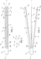
- the control member 20 may include a plurality of tine members. For example, as shown in Figs. 1-3 , the control member 20 comprises five tine members 35-39 disposed about the circumference of the control member 20, as best seen in Fig. 2 , although only three tine members 35-37 are shown for clarity in the side views of Fig. 1 and Fig. 3 . Any number of tine members may be employed, that is greater or fewer than five tine members.
- the tine member 35-39 each comprise proximal and distal regions. As shown in Fig. 1 , the tine member 35 comprises a proximal region 35a and a distal region 35b, while the tine member 36 comprises a proximal region 36a and a distal region 36b, and the tine member 37 comprises a proximal region 37a and a distal region 37b.
- the proximal regions of the tine members may form a tip that may be tapered or blunt.
- the tine members 35-39 are formed into the cannula 26 by forming one or more longitudinal slits in lateral surfaces of the cannula 26, for example using a laser or other suitable cutting technique, along the proximal region 22 of the control member 20.
- the tine members also may be attached to the cannula 26 by soldering, welding, or other methods.
- the provision of a proximal longitudinal slit 47 separates the proximal regions 35a and 36a of the adjacent tine members 35 and 36.
- a proximal longitudinal slit 48 separates the proximal regions 36a and 37a of the adjacent tine members 36 and 37.
- a distal longitudinal slit 45 formed into the cannula 26 separates the distal regions 35b and 36b of adjacent tine members 35 and 36, respectively, while the provision of a distal longitudinal slit 46 formed into the cannula 26 separates the distal regions 36b and 37b of adjacent tine members 36 and 37, respectively, as shown Fig. 1 .
- a length of the proximal longitudinal slits 47 and 48 is less than a length of the distal longitudinal slits 45 and 46. Accordingly, the proximal regions of the tine members 35-39 comprise a length L 1 , while the distal regions of the tine members 35-39 comprise a length L 2 , whereby the length L 1 is less than the length L 2 , as shown in Fig. 3 . In one example, the length L 2 is about 2 to 8 times greater than the length L 1 . Solely by way of example, the length L 2 may range from about 2 to 20 cm, while the length L 1 may range from about 0.5 to about 6 cm.
- the length L 1 preferably is sufficient to cause the proximal regions of one or more tine members 35-39 to engage a portion of a stent, for example by being disposed through a bore of the stent, as described in Figs. 9-10 below.
- the proximal longitudinal slits 47 and 48 are circumferentially wider than the distal longitudinal slits 45 and 46. Accordingly, the proximal regions of the tine members 35-39 comprise a width w 1 , while the distal regions of the tine members 35-39 comprise a width w 2 , whereby the width w 1 is less than the width w 2 , as shown in Fig. 3 .
- a stepped portion 40 is formed where the proximal regions 35a-37a transition into the wider distal regions 35b-37b, as shown in Fig. 1 and Fig. 3 .
- the stepped portion 40 preferably is sized and configured to engage and/or abut a portion of a stent, for purposes explained further below.
- the control member 20 has a contracted delivery configuration, shown in Fig. 1 , and also has a partially or fully deployed expanded configuration, as shown in Fig. 3 .
- the proximal regions of the tine members 35-39 are radially contracted, such that they preferably are substantially parallel to a central longitudinal axis L of the control member 20, as generally depicted in Fig. 1 .
- the proximal region of at least one of the tine members 35-39 expands radially outward relative to the central longitudinal axis L, as depicted in Fig. 3 .
- the tine members 35-39 are selectively movable in incremental amounts between the contracted and expanded configurations shown in Figs. 1 and 3 , respectively.
- the proximal regions of the tine members 35-39 are selectively movable in incremental amounts in both radially inward and outward directions, to facilitate positioning of a stent within a body passage in a controlled manner.
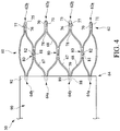
- an exemplary stent-graft 50 having a proximally-located stent 60 coupled to a graft material 90, may be deployed in a controlled manner using the control member 20 of Figs. 1-3 .
- the stent 60 may be manufactured from a continuous cylinder into which a pattern may be cut by a laser or by chemical etching to produce slits in the wall of the cylinder.
- the resulting structure may then be heat set to give it a desired final configuration.
- the final configuration may include a shape having a series of proximal apices and a series of distal apices.
- a proximal end 62 of the stent 60 may comprise multiple adjacent proximal apices 62a and 62b, while a distal end 64 of the stent 20 may comprise multiple adjacent distal apices 64a and 64b, as shown in Fig. 4 .
- the stent 60 may be provided in accordance with a self-expanding attachment stent, for example, described in co-pending U.S. Application Serial No. 12/364,162, filed on February 2, 2009 .
- At least one pair of adjacent, proximal apices 62a and 62b may comprise different features.
- a first proximal apex 62a may comprise an end region 70 having an aperture or bore 71 formed therein, wherein the bore 71 is configured to receive a proximal region of one of the tine members 35-39, as explained further below.
- a second, adjacent proximal apex 62b may comprise an end region 75 having an integral barb 77 formed therein, as shown in Fig. 4 .
- the barb 77 may be formed by laser cutting a desired barb shape into the end regions 75.
- a slit 76 therefore is formed into each end region 75 after the desired barb shape is formed, as shown in Fig. 4 .
- a main body of the barb 77 may be bent in a radially outward direction with respect to the end region 75.
- the angle may comprise any acute angle, or alternatively may be substantially orthogonal or obtuse.
- the barb 77 may be sharpened, for example, by grinding the tip of the barb, to facilitate engagement at a target tissue site.
- the apices 62a, 62b may be all the same or may differ from one another. In an embodiment, they may all include barbs 77. In another embodiment, there may not be provided any barbs 77 at the apices 62a, 62b themselves.
- the stent 60 may comprise at least one strut segment disposed between the proximal and distal apices.
- multiple angled strut segments may be disposed between a first proximal apex 62a and a corresponding distal apex 64a, and an identical set of angled strut segments may be disposed between an adjacent, second proximal apex 62b and a corresponding distal apex 64b.
- a first proximal apex 62a extends distally and splits into first and second angled strut segments 67 and 68, respectively, thereby forming a proximal vertex 78, as shown in Fig. 4 .
- the first and second angled strut segments 67 and 68 may be compressed such that they are substantially parallel to one another.
- each distal apex 64a and 64b may extend in a proximal direction and split into the first and second angled strut segments 67 and 68, respectively, thereby forming a distal vertex 79.
- a first angled strut segment 67 may meet with an adjacent second angled strut segment 68, thereby forming a transition region 80.
- the stent 60 may be formed into a continuous, generally cylindrical shape, as shown in Fig. 4 .
- Expansion of the stent 60 is at least partly provided by the angled strut segments 67 and 68, which may be substantially parallel to one another in a compressed state, but may tend to bow outward away from one another in the expanded state shown in Fig. 4 .
- the stent 60 may be formed from any suitable material, such as a laser-cut Nitinol cannula. If manufactured from Nitinol, the stent 60 may be inclined to assume the expanded state shown in Fig. 4 upon removal of a delivery sheath, such as the outer sheath 140 of Fig. 8 below.
- Each transition region 80 may comprise a larger surface area relative to the angled segments, since the transition regions are composed substantially of multiple different angled segments 67 and 68.
- the stent 60 may comprise at least one barb 82 disposed in at least one of the transition regions 80.
- the barb 82 may be formed integrally, as part of the strut, or may comprise an external barb that is adhered to a surface of the transition regions 80. As shown in Fig. 4 , multiple integral barbs 82 are provided. Like the barbs 77 noted above, the barbs 82 may be formed by laser cutting a desired barb shape into the transition regions 80. A slit 81 therefore is formed into the transition region 80 after the desired barb shape is formed, as shown in Fig. 4 .
- transition regions 80 may comprise an increased surface area relative to other regions of the stent 60, it may be easier to perforate portions of the transition regions 80 without adversely affecting the structural integrity of the stent.
- a main body of the barb 82 may be bent in an outward direction at any angle with respect to the transition region 80 and optionally may be sharpened to facilitate engagement at a target tissue site.
- Each of the distal apices 62a and 62b may comprise an end region 88 having a bore 89 formed therein, as shown in Fig. 4 .
- the distal end 64 of the stent 80 may be coupled to a proximal end 92 of the graft material 90.
- the distal apices 62a and 62b may be coupled to the graft material, for example, using one or more sutures that are looped through the graft material and the bores 89 of the stent 80. In this manner, the stent 60 may be used as an attachment stent for endovascular graft fixation.
- the graft material 90 may overlap with an aneurysm to seal off fluid flow into the aneurysm, while the proximal end 62 of the stent 60 may extend in a proximal direction away from the graft material, for example to engage a healthy portion of a vessel wall away from a diseased portion of the aneurysm.
- one or more additional stents may be coupled to an inner or outer surface of the graft material 90, that is at a location distal to the stent 60, to help maintain patency throughout the graft material.
- the stent 60 has a reduced diameter delivery configuration, or a compressed configuration, so that it may be advanced to a target location within a vessel or duct.
- the stent 60 also has an expanded deployed state to apply a radially outward force upon at least a portion of a vessel or duct, for example to maintain patency within a passageway or to hold open the lumen of a graft. In the expanded state, fluid flow is allowed through a central lumen of the stent 60.
- the struts of the stent 60 may comprise a substantially flat wire profile or may comprise a rounded profile. As best seen in Fig. 4 , the struts of the stent 60 generally comprise a flat wire profile.
- the stent 60 may be manufactured from a super-elastic material.
- the super-elastic material may comprise a shape-memory alloy, such as a nickel titanium alloy (Nitinol).
- Nitinol nickel titanium alloy
- the stent 60 may be heat-set into the desired expanded state, whereby the stent 60 can assume a relaxed configuration in which it assumes the preconfigured first expanded inner diameter upon application of a certain cold or hot medium.
- the stent 60 may be made from other metals and alloys that allow the stent 60 to return to its original, expanded configuration upon deployment, without inducing a permanent strain on the material due to compression.
- the stent 60 may comprise other materials such as stainless steel, cobalt-chrome alloys, amorphous metals, tantalum, platinum, gold and titanium.
- the stent 60 also may be made from non-metallic materials, such as thermoplastics and other polymers.
- stent 60 While one exemplary stent 60 is shown in Fig. 4 and described in Figs. 9-10 below, various alternative stent configurations may be used in conjunction with the control member 20 of Figs. 1-3 and the other apparatus described further in Figs. 5-10 below. Moreover, the stent may be deployed alone, or as part of a stent-graft system, as depicted herein, or as part of any other implantable medical device.
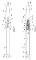
- FIG. 5 a side-sectional view of an inner cannula 100 and an atraumatic tip 110, which may be used as part of a deployment device in conjunction with the control member 20, are shown.
- the inner cannula 100 comprises a tubular member having proximal and distal regions, and a lumen 104 extending between the proximal and distal regions.
- the lumen 104 of the inner cannula 100 is sized to allow the inner cannula 100 to be advanced over a wire guide 108, as depicted in Fig. 5 .
- the atraumatic tip 110 may be affixed to an exterior surface 103 along the distal region of the inner cannula 100, using a suitable adhesive or mechanical attachment mechanism, as depicted in Fig. 5 .
- the atraumatic tip 110 may be formed from an atraumatic material, which comprises proximal and distal ends 112 and 114, respectively.
- the proximal end 112 comprises a smaller outer diameter relative to the distal end 114, with a taper 115 disposed therebetween.
- the proximal end 112 of the atraumatic tip 110 may be substantially flush with a proximal end 102 of the inner cannula 100, as depicted in Fig. 5 .
- the atraumatic tip 110 further comprises a distal recess 117, which may be formed by providing a tapered inner surface 118 at the distal end 114 of the atraumatic tip 110, as shown in Fig. 5 .
- the distal recess 117 of the atraumatic tip 110 may receive a proximal portion of the control member 20 and the stent 60 during delivery of the stent 60 in the contracted delivery configuration.
- the control member 20 of Figs. 1-3 is coupled to the exterior surface 103 of the inner cannula 100.
- the distal region 24 of the control member 20 may be secured to the exterior surface 103 of the inner cannula 100 at an attachment region 109, for example using a solder, weld, or other suitable means.
- the control member 20 is secured to the inner cannula 100 at a location such that a portion of the proximal regions 35a-37a of the tine members 35-37 may be disposed within the inner recess 117 of the atraumatic tip 110 when the tine members are in the contracted delivery configuration, as shown in Fig. 6 .
- tine members 35-39 are not rigidly secured to the inner cannula 100, but rather may expand in a radially outward direction, that is away from the inner cannula 100 and the atraumatic tip 110, in a deployed or partially deployed configuration.
- the inner cannula 100 extends proximally past the attachment region 109 and through the tine members 35-37. A portion of the inner cannula 100, which is disposed beneath the tine members 35-37, is not shown in Fig. 6 for illustrative purposes. However, the proximal end 102 of the inner cannula extends distal to the tine members 35-37 and may be affixed to the proximal end 112 of the atraumatic tip 110, as shown in Fig. 5 .
- a side view illustration depicts an outer cannula 120 disposed over the apparatus of Fig. 6 .
- the outer cannula 120 comprises proximal and distal regions and a lumen 124 extending therebetween.
- the lumen 124 comprises an inner diameter that is larger than an outer diameter of the inner cannula 100, thereby permitting movement of the outer cannula 120 over the inner cannula 100.
- longitudinal movement of outer cannula 120 with respect to the inner cannula 100 permits selective expansion and retraction of the tine members 35-39 of the control member 20, thereby facilitating controlled expansion, and if necessary contraction, of the stent 60.
- the stent-graft 50 of Fig. 4 is coupled to the control member 20 in the contracted delivery configuration.
- the graft 90 of the stent-graft 50 may be placed over the outer cannula 120.
- At least a portion of the proximal end 62 of the stent 60 is coupled to the control member 20.
- each of the alternating proximal apices 62a of the stent 60 is coupled to one of the tine members 35-39, as best seen in Figs. 9-10 below.
- the proximal region 35a of the tine member 35 may be looped through the bore 71 formed in one of the proximal apices 62a of the stent 60, as depicted in Figs. 9-10 .
- the stepped portion 40 of the tine member 35 may abut the proximal vertex 78 of the stent 60.
- the remaining tine members 36-39 may be coupled to the other proximal apices 62a of the stent 60 in a similar manner.
- the stepped portions 40 on each of the tine members 35-39 may engage and/or abut the stent 60 and substantially inhibit distal movement of the stent 60. In this manner, the stent 60 may remain securely coupled to the control member 20. It should be noted that the tine members 35-39 are not disposed through the alternating proximal apices 62b, which comprise the barbs 77.
- a proximal portion of the tine members 35-39 and a proximal portion of the stent 60 may extend into the inner recess 117 at the distal end 114 of the atraumatic tip 110, as depicted in Fig. 8 .
- an outer sheath 140 is used to retain the stent-graft 50 in the contracted delivery configuration shown in Fig. 8 .
- the outer sheath 140 has proximal and distal regions and a lumen 144 extending therebetween.
- a proximal end 142 of the outer sheath 140 extends over the stent 60 of the stent-graft 50, and may abut the distal end 114 of the atraumatic tip 110, as depicted in Fig. 8 .
- the stent-graft 50 may be advanced towards a target site within a patient's vessel or duct over the wire guide 108.
- a physician may incrementally deploy the stent 60, and also may incrementally contract the stent 60 as needed, thereby facilitating improved deployment and positioning of the stent 60.
- the stent 60 is generally aligned with a region of the body passage where it is desired to deploy the stent 60. This may be performed under fluoroscopic guidance or other suitable imaging techniques.
- one or more radiopaque markers are provided on the stent 60 to facilitate alignment within the body passage.
- the outer sheath 140 of Fig. 8 may be distally retracted to expose the stent-graft 50.
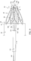
- the stent 60 may partially self-expand, as depicted in Fig. 9 , such that the proximal end 62 of the stent 60 may no longer engage the inner recess 117 at the distal end 114 of the atraumatic tip 110.
- the stent segments begin to urge each of the tine members 35-39 in a radially outward direction, as depicted in Fig. 9 .
- the longitudinal positioning of the outer cannula 120 may be used to limit the maximum radial expansion of the tine members 35-39, which in turn may limit the maximum radial expansion of at least the proximal end 62 of the stent 60. More specifically, when the outer cannula 120 is in a relatively proximal longitudinal position, as shown in Fig. 9 , the outer cannula 120 may impose a relatively stiff restraining force upon the distal regions 35b and 356b of the tine members, which may prevent the proximal regions 35a and 36a of the tine members from further radially expanding. At this time, the stent 60 cannot further radially expand.
- the stent 60 cannot slide backwards, i.e., distally, because the vertices 78, angled strut segments 67 and 68, or other strut portions will engage the stepped portion 40 of the tine members 35-39 of the control member 20.
- the outer cannula 120 may be distally retracted with respect to the inner cannula 100.
- the outer cannula 120 may expose a greater portion of the tine members 35-39, and also may expose the cannula 26 and attachment region 109 between the control member 20 and the inner cannula 100. Since the tine members 35-39 are no longer substantially constrained, the tine members 35-39 may have greater flexibility, and the radial force provided by the desired self-expansion of the stent 60 may urge the tine members 35-39 further radially outward, as shown in Fig. 10 .
- the outer cannula 120 may permit movement of the tine members 35-39 an incremental amount between the contracted and expanded configurations, both in radially inward and outward directions, to facilitate positioning of the stent within the body passage.
- a physician may wish to advance the outer cannula 120 proximally with respect to the inner cannula 100 to recapture or retract the stent 60. Accordingly, any number of repositioning attempts may be made before final deployment of the stent 60.
- the outer cannula 120 may be retracted distally a sufficient amount that causes the barbs 77 and 82 to fully engage the inner wall of the body passage.
- the inner cannula 100 then may be distally retracted to pull the proximal regions 35a and 36a of the tine members 35 and 36, as well as the other tine members, through their associated bores 71 in the stent.
- the tine members 35-39 then may be retracted distally into the confines of the outer cannula 120, and the inner and outer cannulae 100 and 120 may be removed from the patient's body.
- the provision of a delivery system employing a control member 20, as described above may permit improved positioning of the stent-graft 50 inside of a body, and also permits an amount of recapture of the stent 60 prior to full deployment. Moreover, any undesirable foreshortening, which typically occurs when conventional trigger wires release a stent, may be reduced or eliminated by use of the control member 20 and associated tine members.
- each stent apex 62a, 62b it is preferred that there is provided a tine member for each stent apex 62a, 62b but in some embodiments only some of the apices of the stent may have associated tine members, in which case the stent 60 would contract by the contracting force over the entire stent produced by those parts of the stent which are coupled to the tines 35-37.
Description
- The present invention relates generally to medical devices, and more particularly, to apparatus for improved deployment of stents or other implantable medical devices.
- Stents may be inserted into an anatomical vessel or duct for various purposes. Stents may maintain or restore patency in a formerly blocked or constricted passageway, for example, following a balloon angioplasty procedure. Other stents may be used for different procedures, for example, stents placed in or about a graft have been used to hold the graft in an open configuration to treat an aneurysm. Additionally, stents coupled to one or both ends of a graft may extend proximally or distally away from the graft to engage a healthy portion of a vessel wall away from a diseased portion of an aneurysm to provide endovascular graft fixation.
- Stents may be either self-expanding or balloon-expandable, or they can have characteristics of both types of stents. Self-expanding stents may be delivered to a target site in a compressed configuration and subsequently expanded by removing a delivery sheath, removing trigger wires and/or releasing diameter reducing ties. With self-expanding stents, the stents expand primarily based on their own expansive force without the need for further mechanical expansion. In a stent made of a shape-memory alloy such as Nitinol, the shape-memory alloy may be employed to cause the stent to return to a predetermined configuration upon removal of the sheath or other device maintaining the stent in its pre-deployment configuration.
- When trigger wires are used as a deployment control mechanism, the trigger wires may releasably couple the proximal and/or distal ends of a stent or stent-graft to a delivery catheter. Typically, one or more trigger wires are looped through a portion of the stent near a vertex of the stent. For example, trigger wires may be used to restrain a "Z-stent" or Gianturco stent formed of a series of substantially straight segments interconnected by a series of bent segments. The trigger wires may be disposed through, and pull upon, the bent segments to pull the stent closely against the delivery catheter. Trigger wires also may be used in conjunction with different stent designs, such as cannula-cut stents having acute or pointed bends. In the latter embodiment, the trigger wires may be looped around one or more vertices formed beneath the proximal and/or distal apices, for example a location where an individual apex splits into two separate strut segments.
- If trigger wires are used to deploy stents, typically the actuation of the trigger wire causes full radial expansion of the stent, such that the stent engages an inner wall of a duct, vessel or the like. Barbs of the stent may engage the body passage, and the deployed stent may be difficult or impossible to recapture or reposition at this time. Further, upon release of the trigger wire, as the stent is expanding it may foreshorten or otherwise move an undesired amount with respect to the body passage. Therefore, the actuation of a conventional trigger wire may yield inaccurate positioning of a stent that engages a body passage and may be difficult to retrieve.
- The problems are manifest not only in the deployment of stents but also in the deployment of stent grafts and other implantable medical devices.
-
WO 06/09013 A1 US 2006/0020319 A1 discloses a stent delivery catheter. - The present invention according to independent claims 1 and 9 seeks to provide an improved apparatus, introducer, for deploying a stent or other implantable medical device for deploying an implantable medical device.
- The present embodiments provide apparatus for facilitating deployment of a stent or other medical device. In one embodiment, the apparatus comprises a control member having at least one tine member. A proximal region of at least one of the tine members is configured to engage an associated portion of a stent. The control member comprises a contracted delivery configuration in which the proximal region of the at least one of the tine member is radially contracted, relative to a central longitudinal axis of the control member, to radially constrain the associated portion of the stent. The control member also comprises an expanded configuration in which the proximal region of the at least one tine member expands radially outward relative to the central longitudinal axis to allow the stent to engage a body passage. The proximal region of the at least one tine member is selectively and incrementally movable between the contracted and expanded configurations to facilitate positioning of the stent.
- The control member is formed from a cannula having at least one slit formed therein, where the slit separates adjacent tine members. The cannula may comprise a shape memory alloy or other suitable material. Further, the proximal region of the at least one tine member comprises a first width, and a distal region of the at least one tine member comprises a second width. The first width is less than the second width to form a stepped portion between the proximal and distal regions of the at least one tine member. The proximal region of the tine member may be sized to be advanced through a bore of the stent, while the distal region of the tine member comprises a width larger than the bore of the stent. Accordingly, the stepped portion may be configured to abut the stent to substantially inhibit distal movement of the stent with respect to the control member when the at least one tine member is coupled to the stent.
- In one exemplary method of use, an outer cannula having a lumen is sized for longitudinal movement over a portion of the distal region of the at least one tine member. Selective proximal advancement of the outer cannula over the distal region of the at least one tine member incrementally urges the proximal region of the at least one tine member in a radially inward direction relative to the central longitudinal axis. Conversely, selective distal retraction of the outer cannula over the distal region of the at least one tine member permits incremental radial expansion of the proximal region of the at least one tine members relative to the central longitudinal axis. Accordingly, the amount of incremental expansion or contraction of the stent may be controlled in part by the selective incremental movement of the outer cannula with respect to the tine members.
- Advantageously, the provision of a delivery system employing the apparatus and methods described herein may permit improved positioning of a stent, or stent-graft, inside of a body passage. The apparatus and methods also permit an amount of recapture of a stent prior to full deployment. Moreover, any undesirable foreshortening, which typically occurs when conventional trigger wires release a stent, may be reduced or eliminated by use of the control member and associated tine members.
- The present invention may be used for the deployment of stents, stent grafts, vena cava filters and other implantable medical devices.
- Embodiments of the present invention are described below, by way of example only, with reference to the accompanying drawings, in which:
-
Fig. 1 is a side view of an exemplary control member in a contracted state; -
Fig. 2 is a cross-sectional view along line A--A ofFig. 1 ; -
Fig. 3 is a side view of the control member ofFig. 1 in a partially or fully expanded state; -
Fig. 4 is a side view depicting a proximal region of an exemplary stent-graft for used with the control member ofFigs. 1-3 ; -
Fig. 5 is a side-sectional view of an inner cannula disposed over a wire guide; -
Fig. 6 is a side view of the control member ofFigs. 1-3 coupled to the inner cannula ofFig. 5 ; -
Fig. 7 is a side view showing an outer cannula disposed over a portion of the apparatus ofFig. 6 ; -
Fig. 8 is generally a side view illustrating the stent-graft ofFig. 4 used with the apparatus ofFigs. 5-7 . An outer sheath is shown in a side-sectional format for illustrative purposes; and -
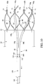
Figs. 9-10 are side views illustrating an exemplary sequence of controlled deployment of the stent-graft ofFig. 4 . - In the present application, the term "proximal" refers to a direction that is generally closest to the heart during a medical procedure, while the term "distal" refers to a direction that is furthest from the heart during a medical procedure.
- The preferred embodiments taught below are described in connection with the deployment of a stent or stent graft. It is to be understood that the apparatus and method can be used for deploying of a range of implantable medical devices including stents, stent grafts, vena cava filters, occlusion devices and so on.
- Referring to
Figs. 1-3 , an apparatus for deploying a stent, or stent-graft, is disclosed. The apparatus comprises acontrol member 20 having proximal anddistal regions control member 20 may be formed from acannula 26 having alumen 27 extending between the proximal anddistal regions control member 20 may permit at least partial radial expansion of a stent within a body passage, and also may permit at least partial radial contraction of the stent to permit repositioning of the stent within the body passage. - The
cannula 26 of thecontrol member 20 may comprise a shape-memory material such as a nickel-titanium alloy, or alternatively, stainless steel or another suitable material, as explained below. Theproximal region 22 of thecontrol member 20 comprises at least one tine member configured to engage a portion of a stent. Thecontrol member 20 may include a plurality of tine members. For example, as shown inFigs. 1-3 , thecontrol member 20 comprises five tine members 35-39 disposed about the circumference of thecontrol member 20, as best seen inFig. 2 , although only three tine members 35-37 are shown for clarity in the side views ofFig. 1 and Fig. 3 . Any number of tine members may be employed, that is greater or fewer than five tine members. - The tine member 35-39 each comprise proximal and distal regions. As shown in
Fig. 1 , thetine member 35 comprises aproximal region 35a and adistal region 35b, while thetine member 36 comprises aproximal region 36a and adistal region 36b, and thetine member 37 comprises aproximal region 37a and adistal region 37b. The proximal regions of the tine members may form a tip that may be tapered or blunt. - The tine members 35-39 are formed into the
cannula 26 by forming one or more longitudinal slits in lateral surfaces of thecannula 26, for example using a laser or other suitable cutting technique, along theproximal region 22 of thecontrol member 20. The tine members also may be attached to thecannula 26 by soldering, welding, or other methods. The provision of a proximallongitudinal slit 47 separates theproximal regions adjacent tine members longitudinal slit 48 separates theproximal regions adjacent tine members longitudinal slit 45 formed into thecannula 26 separates thedistal regions adjacent tine members longitudinal slit 46 formed into thecannula 26 separates thedistal regions adjacent tine members Fig. 1 . - In one embodiment, a length of the proximal
longitudinal slits longitudinal slits Fig. 3 . In one example, the length L2 is about 2 to 8 times greater than the length L1. Solely by way of example, the length L2 may range from about 2 to 20 cm, while the length L1 may range from about 0.5 to about 6 cm. The length L1 preferably is sufficient to cause the proximal regions of one or more tine members 35-39 to engage a portion of a stent, for example by being disposed through a bore of the stent, as described inFigs. 9-10 below. Further, according to the invention the proximallongitudinal slits longitudinal slits Fig. 3 . Therefore, a steppedportion 40 is formed where theproximal regions 35a-37a transition into the widerdistal regions 35b-37b, as shown inFig. 1 and Fig. 3 . The steppedportion 40 preferably is sized and configured to engage and/or abut a portion of a stent, for purposes explained further below. - The
control member 20 has a contracted delivery configuration, shown inFig. 1 , and also has a partially or fully deployed expanded configuration, as shown inFig. 3 . In the contracted delivery configuration, the proximal regions of the tine members 35-39 are radially contracted, such that they preferably are substantially parallel to a central longitudinal axis L of thecontrol member 20, as generally depicted inFig. 1 . In the partially or fully expanded configurations, the proximal region of at least one of the tine members 35-39 expands radially outward relative to the central longitudinal axis L, as depicted inFig. 3 . - As explained with regard to
Figs. 9-10 below, the tine members 35-39 are selectively movable in incremental amounts between the contracted and expanded configurations shown inFigs. 1 and 3 , respectively. In one exemplary method, described below, the proximal regions of the tine members 35-39 are selectively movable in incremental amounts in both radially inward and outward directions, to facilitate positioning of a stent within a body passage in a controlled manner. - Referring now to
Fig. 4 , an exemplary stent-graft 50, having a proximally-locatedstent 60 coupled to agraft material 90, may be deployed in a controlled manner using thecontrol member 20 ofFigs. 1-3 . Thestent 60 may be manufactured from a continuous cylinder into which a pattern may be cut by a laser or by chemical etching to produce slits in the wall of the cylinder. The resulting structure may then be heat set to give it a desired final configuration. As shown inFig. 4 , the final configuration may include a shape having a series of proximal apices and a series of distal apices. Aproximal end 62 of thestent 60 may comprise multiple adjacentproximal apices distal end 64 of thestent 20 may comprise multiple adjacentdistal apices Fig. 4 . Thestent 60 may be provided in accordance with a self-expanding attachment stent, for example, described in co-pendingU.S. Application Serial No. 12/364,162, filed on February 2, 2009 - In
Fig. 4 , at least one pair of adjacent,proximal apices Fig. 4 , a firstproximal apex 62a may comprise anend region 70 having an aperture or bore 71 formed therein, wherein thebore 71 is configured to receive a proximal region of one of the tine members 35-39, as explained further below. A second, adjacentproximal apex 62b may comprise anend region 75 having anintegral barb 77 formed therein, as shown inFig. 4 . Thebarb 77 may be formed by laser cutting a desired barb shape into theend regions 75. A slit 76 therefore is formed into eachend region 75 after the desired barb shape is formed, as shown inFig. 4 . Once the desired barb shape is cut, a main body of thebarb 77 may be bent in a radially outward direction with respect to theend region 75. The angle may comprise any acute angle, or alternatively may be substantially orthogonal or obtuse. If desired, thebarb 77 may be sharpened, for example, by grinding the tip of the barb, to facilitate engagement at a target tissue site. - The
apices barbs 77. In another embodiment, there may not be provided anybarbs 77 at theapices - Referring still to
Fig. 4 , thestent 60 may comprise at least one strut segment disposed between the proximal and distal apices. For example, multiple angled strut segments may be disposed between a firstproximal apex 62a and a correspondingdistal apex 64a, and an identical set of angled strut segments may be disposed between an adjacent, secondproximal apex 62b and a correspondingdistal apex 64b. By way of example, a firstproximal apex 62a extends distally and splits into first and secondangled strut segments proximal vertex 78, as shown inFig. 4 . In a compressed state, the first and secondangled strut segments distal apex angled strut segments distal vertex 79. A firstangled strut segment 67 may meet with an adjacent secondangled strut segment 68, thereby forming atransition region 80. In this manner, thestent 60 may be formed into a continuous, generally cylindrical shape, as shown inFig. 4 . - Expansion of the
stent 60 is at least partly provided by theangled strut segments Fig. 4 . Thestent 60 may be formed from any suitable material, such as a laser-cut Nitinol cannula. If manufactured from Nitinol, thestent 60 may be inclined to assume the expanded state shown inFig. 4 upon removal of a delivery sheath, such as theouter sheath 140 ofFig. 8 below. - Each
transition region 80 may comprise a larger surface area relative to the angled segments, since the transition regions are composed substantially of multiple differentangled segments stent 60 may comprise at least onebarb 82 disposed in at least one of thetransition regions 80. Thebarb 82 may be formed integrally, as part of the strut, or may comprise an external barb that is adhered to a surface of thetransition regions 80. As shown inFig. 4 , multipleintegral barbs 82 are provided. Like thebarbs 77 noted above, thebarbs 82 may be formed by laser cutting a desired barb shape into thetransition regions 80. A slit 81 therefore is formed into thetransition region 80 after the desired barb shape is formed, as shown inFig. 4 . Since thetransition regions 80 may comprise an increased surface area relative to other regions of thestent 60, it may be easier to perforate portions of thetransition regions 80 without adversely affecting the structural integrity of the stent. Once the desired barb shape is cut, a main body of thebarb 82 may be bent in an outward direction at any angle with respect to thetransition region 80 and optionally may be sharpened to facilitate engagement at a target tissue site. - Each of the
distal apices end region 88 having abore 89 formed therein, as shown inFig. 4 . Thedistal end 64 of thestent 80 may be coupled to aproximal end 92 of thegraft material 90. Thedistal apices bores 89 of thestent 80. In this manner, thestent 60 may be used as an attachment stent for endovascular graft fixation. For example, thegraft material 90 may overlap with an aneurysm to seal off fluid flow into the aneurysm, while theproximal end 62 of thestent 60 may extend in a proximal direction away from the graft material, for example to engage a healthy portion of a vessel wall away from a diseased portion of the aneurysm. As will be apparent, one or more additional stents may be coupled to an inner or outer surface of thegraft material 90, that is at a location distal to thestent 60, to help maintain patency throughout the graft material. - The
stent 60 has a reduced diameter delivery configuration, or a compressed configuration, so that it may be advanced to a target location within a vessel or duct. Thestent 60 also has an expanded deployed state to apply a radially outward force upon at least a portion of a vessel or duct, for example to maintain patency within a passageway or to hold open the lumen of a graft. In the expanded state, fluid flow is allowed through a central lumen of thestent 60. Further, the struts of thestent 60 may comprise a substantially flat wire profile or may comprise a rounded profile. As best seen inFig. 4 , the struts of thestent 60 generally comprise a flat wire profile. - The
stent 60 may be manufactured from a super-elastic material. Solely by way of example, the super-elastic material may comprise a shape-memory alloy, such as a nickel titanium alloy (Nitinol). If thestent 60 comprises a self-expanding material such as Nitinol, the stent may be heat-set into the desired expanded state, whereby thestent 60 can assume a relaxed configuration in which it assumes the preconfigured first expanded inner diameter upon application of a certain cold or hot medium. Alternatively, thestent 60 may be made from other metals and alloys that allow thestent 60 to return to its original, expanded configuration upon deployment, without inducing a permanent strain on the material due to compression. Solely by way of example, thestent 60 may comprise other materials such as stainless steel, cobalt-chrome alloys, amorphous metals, tantalum, platinum, gold and titanium. Thestent 60 also may be made from non-metallic materials, such as thermoplastics and other polymers. - While one
exemplary stent 60 is shown inFig. 4 and described inFigs. 9-10 below, various alternative stent configurations may be used in conjunction with thecontrol member 20 ofFigs. 1-3 and the other apparatus described further inFigs. 5-10 below. Moreover, the stent may be deployed alone, or as part of a stent-graft system, as depicted herein, or as part of any other implantable medical device. - Referring now to
Fig. 5 , a side-sectional view of aninner cannula 100 and anatraumatic tip 110, which may be used as part of a deployment device in conjunction with thecontrol member 20, are shown. Theinner cannula 100 comprises a tubular member having proximal and distal regions, and alumen 104 extending between the proximal and distal regions. Thelumen 104 of theinner cannula 100 is sized to allow theinner cannula 100 to be advanced over awire guide 108, as depicted inFig. 5 . - The
atraumatic tip 110 may be affixed to anexterior surface 103 along the distal region of theinner cannula 100, using a suitable adhesive or mechanical attachment mechanism, as depicted inFig. 5 . Theatraumatic tip 110 may be formed from an atraumatic material, which comprises proximal anddistal ends proximal end 112 comprises a smaller outer diameter relative to thedistal end 114, with ataper 115 disposed therebetween. Theproximal end 112 of theatraumatic tip 110 may be substantially flush with aproximal end 102 of theinner cannula 100, as depicted inFig. 5 . Theatraumatic tip 110 further comprises adistal recess 117, which may be formed by providing a taperedinner surface 118 at thedistal end 114 of theatraumatic tip 110, as shown inFig. 5 . As will be explained in further detail below, thedistal recess 117 of theatraumatic tip 110 may receive a proximal portion of thecontrol member 20 and thestent 60 during delivery of thestent 60 in the contracted delivery configuration. - Referring now to
Fig. 6 , thecontrol member 20 ofFigs. 1-3 is coupled to theexterior surface 103 of theinner cannula 100. Thedistal region 24 of thecontrol member 20 may be secured to theexterior surface 103 of theinner cannula 100 at anattachment region 109, for example using a solder, weld, or other suitable means. Preferably, thecontrol member 20 is secured to theinner cannula 100 at a location such that a portion of theproximal regions 35a-37a of the tine members 35-37 may be disposed within theinner recess 117 of theatraumatic tip 110 when the tine members are in the contracted delivery configuration, as shown inFig. 6 . It should be noted that the tine members 35-39 are not rigidly secured to theinner cannula 100, but rather may expand in a radially outward direction, that is away from theinner cannula 100 and theatraumatic tip 110, in a deployed or partially deployed configuration. - Further, it should be noted that the
inner cannula 100 extends proximally past theattachment region 109 and through the tine members 35-37. A portion of theinner cannula 100, which is disposed beneath the tine members 35-37, is not shown inFig. 6 for illustrative purposes. However, theproximal end 102 of the inner cannula extends distal to the tine members 35-37 and may be affixed to theproximal end 112 of theatraumatic tip 110, as shown inFig. 5 . - Referring now to
Fig. 7 , a side view illustration depicts anouter cannula 120 disposed over the apparatus ofFig. 6 . Theouter cannula 120 comprises proximal and distal regions and alumen 124 extending therebetween. Thelumen 124 comprises an inner diameter that is larger than an outer diameter of theinner cannula 100, thereby permitting movement of theouter cannula 120 over theinner cannula 100. As will be set forth inFigs. 9-10 below, longitudinal movement ofouter cannula 120 with respect to theinner cannula 100 permits selective expansion and retraction of the tine members 35-39 of thecontrol member 20, thereby facilitating controlled expansion, and if necessary contraction, of thestent 60. - Referring to
Fig. 8 , the stent-graft 50 ofFig. 4 is coupled to thecontrol member 20 in the contracted delivery configuration. In this state, thegraft 90 of the stent-graft 50 may be placed over theouter cannula 120. At least a portion of theproximal end 62 of thestent 60 is coupled to thecontrol member 20. Preferably, each of the alternatingproximal apices 62a of thestent 60 is coupled to one of the tine members 35-39, as best seen inFigs. 9-10 below. More specifically, theproximal region 35a of thetine member 35 may be looped through thebore 71 formed in one of theproximal apices 62a of thestent 60, as depicted inFigs. 9-10 . At this time, the steppedportion 40 of thetine member 35 may abut theproximal vertex 78 of thestent 60. - The remaining tine members 36-39 may be coupled to the other
proximal apices 62a of thestent 60 in a similar manner. The steppedportions 40 on each of the tine members 35-39 may engage and/or abut thestent 60 and substantially inhibit distal movement of thestent 60. In this manner, thestent 60 may remain securely coupled to thecontrol member 20. It should be noted that the tine members 35-39 are not disposed through the alternatingproximal apices 62b, which comprise thebarbs 77. Further, it should be noted that during delivery, when thestent 60 is coupled to the tine members 35-39 of thecontrol member 20 as noted above, a proximal portion of the tine members 35-39 and a proximal portion of thestent 60 may extend into theinner recess 117 at thedistal end 114 of theatraumatic tip 110, as depicted inFig. 8 . - Preferably, an
outer sheath 140 is used to retain the stent-graft 50 in the contracted delivery configuration shown inFig. 8 . Theouter sheath 140 has proximal and distal regions and alumen 144 extending therebetween. Aproximal end 142 of theouter sheath 140 extends over thestent 60 of the stent-graft 50, and may abut thedistal end 114 of theatraumatic tip 110, as depicted inFig. 8 . With the entire assembly provided as shown inFig. 8 , the stent-graft 50 may be advanced towards a target site within a patient's vessel or duct over thewire guide 108. - Referring now to
Figs. 9-10 , prior to complete deployment of the stent-graft 50 into engagement with an inner wall of a body passage, a physician may incrementally deploy thestent 60, and also may incrementally contract thestent 60 as needed, thereby facilitating improved deployment and positioning of thestent 60. In a first step, with the apparatus delivered over thewire guide 108 as shown inFig. 8 , thestent 60 is generally aligned with a region of the body passage where it is desired to deploy thestent 60. This may be performed under fluoroscopic guidance or other suitable imaging techniques. Preferably, one or more radiopaque markers are provided on thestent 60 to facilitate alignment within the body passage. - Upon initial alignment of the
stent 60, theouter sheath 140 ofFig. 8 may be distally retracted to expose the stent-graft 50. At this time, thestent 60 may partially self-expand, as depicted inFig. 9 , such that theproximal end 62 of thestent 60 may no longer engage theinner recess 117 at thedistal end 114 of theatraumatic tip 110. As theproximal end 62 of thestent 60 self-expands, the stent segments begin to urge each of the tine members 35-39 in a radially outward direction, as depicted inFig. 9 . - However, the longitudinal positioning of the
outer cannula 120 may be used to limit the maximum radial expansion of the tine members 35-39, which in turn may limit the maximum radial expansion of at least theproximal end 62 of thestent 60. More specifically, when theouter cannula 120 is in a relatively proximal longitudinal position, as shown inFig. 9 , theouter cannula 120 may impose a relatively stiff restraining force upon thedistal regions 35b and 356b of the tine members, which may prevent theproximal regions stent 60 cannot further radially expand. Moreover, thestent 60 cannot slide backwards, i.e., distally, because thevertices 78,angled strut segments portion 40 of the tine members 35-39 of thecontrol member 20. - Accordingly, when the
outer sheath 140 is in a relatively proximal longitudinal position, and theouter cannula 120 imposes a relatively stiff restraining force upon the tine members 35-39, neither thebarbs 77 nor thebarbs 82 engage the inner wall of the body passage. This allows a physician to reposition the location of thestent 60 within the body passage, if desired. - Referring to
Fig. 10 , in a next step, theouter cannula 120 may be distally retracted with respect to theinner cannula 100. When in a relatively distal longitudinal position, theouter cannula 120 may expose a greater portion of the tine members 35-39, and also may expose thecannula 26 andattachment region 109 between thecontrol member 20 and theinner cannula 100. Since the tine members 35-39 are no longer substantially constrained, the tine members 35-39 may have greater flexibility, and the radial force provided by the desired self-expansion of thestent 60 may urge the tine members 35-39 further radially outward, as shown inFig. 10 . - In this manner, by moving the
outer cannula 120 an incremental amount with respect to theinner cannula 100, theouter cannula 120 may permit movement of the tine members 35-39 an incremental amount between the contracted and expanded configurations, both in radially inward and outward directions, to facilitate positioning of the stent within the body passage. For example, asstent 60 radially expands in a controlled manner due to incremental distal retraction of theouter cannula 120, and thebarbs outer cannula 120 proximally with respect to theinner cannula 100 to recapture or retract thestent 60. Accordingly, any number of repositioning attempts may be made before final deployment of thestent 60. - Upon final positioning, the
outer cannula 120 may be retracted distally a sufficient amount that causes thebarbs inner cannula 100 then may be distally retracted to pull theproximal regions tine members bores 71 in the stent. The tine members 35-39 then may be retracted distally into the confines of theouter cannula 120, and the inner andouter cannulae - Advantageously, the provision of a delivery system employing a
control member 20, as described above, may permit improved positioning of the stent-graft 50 inside of a body, and also permits an amount of recapture of the
stent 60 prior to full deployment. Moreover, any undesirable foreshortening, which typically occurs when conventional trigger wires release a stent, may be reduced or eliminated by use of thecontrol member 20 and associated tine members. - It is preferred that there is provided a tine member for each
stent apex stent 60 would contract by the contracting force over the entire stent produced by those parts of the stent which are coupled to the tines 35-37. - While various embodiments of the invention have been described, the teachings herein are not limited thereto and must be construed having regard to the appended claims. Moreover, the advantages described herein are not necessarily the only advantages of the teachings herein and it is not necessarily expected that every embodiment of the invention will achieve all of the advantages described.
Claims (9)
- An apparatus for deploying an implantable medical device (50) provided with at least one stent (60), including:a control member (20) including a plurality of tine members (35-37), each provided with proximal (35a-37a), and distal (35b-37b) regions, where the proximal regions of the tine members are configured to engage an associated portion of a stent,the control member having a contracted delivery configuration, in which the proximal region of each tine member is radially contracted, and an expanded configuration, in which the proximal region of each tine member is radially expanded relative to a central longitudinal axis,the proximal region of each tine member being selectively movable between the contracted and expanded configurations to facilitate positioning of the stent within a body passage, characterized in that the control member comprises a cannula (26) having at least one slit (45-48) formed therein separating adjacent tine members and wherein the proximal region of each tine member has a first width (W1), and the distal region of each tine member has a second width (W2) greater than the first width, such that a stepped portion (40) is formed between the proximal and distal regions of each tine member.
- The apparatus of claim 1, including an outer cannula (120) having a lumen and sized for longitudinal movement over a portion of the distal region of each tine member, wherein selective proximal advancement of the outer cannula over the distal regions of tine members is configured to urge the proximal regions of the tine members in a radially inward direction relative to the central longitudinal axis.
- The apparatus of claim 2, wherein selective distal retraction of the outer cannula (120) over the distal regions of the tine members is configured to permit radial expansion of the proximal regions of the tine members relative to the central longitudinal axis.
- The apparatus of claim 2 or 3, including:an inner cannula (100) having proximal and distal ends and including a lumen disposed between the proximal and distal ends to permit advancement of the inner cannula over a wire guide,wherein the distal region of the control member (20) is affixed to an outer surface of the inner cannula, andwherein the outer cannula (120) is sized for longitudinal advancement over the inner cannula.
- The apparatus of claim 4, including an atraumatic tip (110) disposed on the proximal end of the inner cannula (100), the atraumatic tip comprising a distal end having an inner recess, and wherein the proximal region of the at least one tine member is disposed within the inner recess during delivery of the stent into the body passage.
- The apparatus of any preceding claim, wherein the control member (20) is formed from or includes a shape memory alloy and the tine members are preconfigured to assume the contracted delivery configuration.
- The apparatus of any preceding claim, wherein the proximal region of each tine member is sized to be advanced through an associated portion of the stent, and wherein the distal region of each tine member includes a width larger than the associated portion of the stent, such that the stepped portion (40) is configured to abut the associated portion of the stent.
- The apparatus of any of claims 1 to 5, including an outer sheath (140) disposed substantially over the outer cannula (120), the inner cannula (100), the control member (20) and the stent (60) during delivery to constrain the tine members in a contracted delivery configuration.
- A combination of an apparatus according to any preceding claim and a stent (60) having a plurality of bores, wherein the proximal regions of the tine members are sized to be advanced through said bores, and wherein the distal regions of the tine members have a width larger than said bores, such that the stepped portion (40) is configured to abut the stent to substantially inhibit distal movement of the stent with respect to the control member when the tine members are coupled to the stent.
Applications Claiming Priority (2)
| Application Number | Priority Date | Filing Date | Title |
|---|---|---|---|
| US9450608P | 2008-09-05 | 2008-09-05 | |
| PCT/US2009/004994 WO2010027485A1 (en) | 2008-09-05 | 2009-09-04 | Apparatus and methods for improve stent deployment |
Publications (2)
| Publication Number | Publication Date |
|---|---|
| EP2349124A1 EP2349124A1 (en) | 2011-08-03 |
| EP2349124B1 true EP2349124B1 (en) | 2018-10-17 |
Family
ID=41350135
Family Applications (1)
| Application Number | Title | Priority Date | Filing Date |
|---|---|---|---|
| EP09789264.0A Active EP2349124B1 (en) | 2008-09-05 | 2009-09-04 | Apparatus for improved stent deployment |
Country Status (5)
| Country | Link |
|---|---|
| US (1) | US9192497B2 (en) |
| EP (1) | EP2349124B1 (en) |
| JP (1) | JP5945119B2 (en) |
| AU (1) | AU2009288697B2 (en) |
| WO (1) | WO2010027485A1 (en) |
Cited By (9)
| Publication number | Priority date | Publication date | Assignee | Title |
|---|---|---|---|---|
| US11304804B2 (en) | 2017-09-19 | 2022-04-19 | Cardiovalve, Ltd. | Prosthetic valve with connecting struts of variable size and tissue anchoring legs of variable size that extend from junctions |
| US11382746B2 (en) | 2017-12-13 | 2022-07-12 | Cardiovalve Ltd. | Prosthetic valve and delivery tool therefor |
| US11491011B2 (en) | 2018-09-17 | 2022-11-08 | Cardiovalve Ltd. | Leaflet-grouping system |
| US11534298B2 (en) | 2015-02-05 | 2022-12-27 | Cardiovalve Ltd. | Prosthetic valve with s-shaped tissue anchors |
| US11633277B2 (en) | 2018-01-10 | 2023-04-25 | Cardiovalve Ltd. | Temperature-control during crimping of an implant |
| US11779458B2 (en) | 2016-08-10 | 2023-10-10 | Cardiovalve Ltd. | Prosthetic valve with leaflet connectors |
| US11793638B2 (en) | 2015-02-05 | 2023-10-24 | Cardiovalve Ltd. | Prosthetic valve with pivoting tissue anchor portions |
| US11793633B2 (en) | 2017-08-03 | 2023-10-24 | Cardiovalve Ltd. | Prosthetic heart valve |
| US11844691B2 (en) | 2013-01-24 | 2023-12-19 | Cardiovalve Ltd. | Partially-covered prosthetic valves |
Families Citing this family (63)
| Publication number | Priority date | Publication date | Assignee | Title |
|---|---|---|---|---|
| US6866679B2 (en) | 2002-03-12 | 2005-03-15 | Ev3 Inc. | Everting stent and stent delivery system |
| US8500792B2 (en) | 2003-09-03 | 2013-08-06 | Bolton Medical, Inc. | Dual capture device for stent graft delivery system and method for capturing a stent graft |
| US8292943B2 (en) | 2003-09-03 | 2012-10-23 | Bolton Medical, Inc. | Stent graft with longitudinal support member |
| US11259945B2 (en) | 2003-09-03 | 2022-03-01 | Bolton Medical, Inc. | Dual capture device for stent graft delivery system and method for capturing a stent graft |
| US9364314B2 (en) | 2008-06-30 | 2016-06-14 | Bolton Medical, Inc. | Abdominal aortic aneurysms: systems and methods of use |
| EP2293838B1 (en) | 2008-07-01 | 2012-08-08 | Endologix, Inc. | Catheter system |
| GB2464977B (en) | 2008-10-31 | 2010-11-03 | William Cook Europe As | Introducer for deploying a stent graft in a curved lumen and stent graft therefor |
| US11376114B2 (en) | 2008-10-31 | 2022-07-05 | Cook Medical Technologies Llc | Introducer for deploying a stent graft in a curved lumen and stent graft therefor |
| BRPI1012599A2 (en) * | 2009-03-13 | 2016-03-22 | Bolton Medical Inc | system and method for placing an endoluminal prosthesis in a surgical site |
| US8870950B2 (en) | 2009-12-08 | 2014-10-28 | Mitral Tech Ltd. | Rotation-based anchoring of an implant |
| US9561102B2 (en) | 2010-06-02 | 2017-02-07 | Medtronic, Inc. | Transcatheter delivery system and method with controlled expansion and contraction of prosthetic heart valve |
| US9763657B2 (en) | 2010-07-21 | 2017-09-19 | Mitraltech Ltd. | Techniques for percutaneous mitral valve replacement and sealing |
| US11653910B2 (en) | 2010-07-21 | 2023-05-23 | Cardiovalve Ltd. | Helical anchor implantation |
| JP6294669B2 (en) | 2011-03-01 | 2018-03-14 | エンドロジックス、インク | Catheter system and method of use thereof |
| WO2013021374A2 (en) | 2011-08-05 | 2013-02-14 | Mitraltech Ltd. | Techniques for percutaneous mitral valve replacement and sealing |
| US8852272B2 (en) | 2011-08-05 | 2014-10-07 | Mitraltech Ltd. | Techniques for percutaneous mitral valve replacement and sealing |
| US9220620B2 (en) | 2011-11-22 | 2015-12-29 | Cook Medical Technologies Llc | Endoluminal prosthesis introducer |
| US9278018B2 (en) | 2011-12-14 | 2016-03-08 | Cook Medical Technologies Llc | Circumferential trigger wire for deploying an endoluminal prosthesis |
| US9072624B2 (en) | 2012-02-23 | 2015-07-07 | Covidien Lp | Luminal stenting |
| US20130226278A1 (en) | 2012-02-23 | 2013-08-29 | Tyco Healthcare Group Lp | Methods and apparatus for luminal stenting |
| WO2013154749A1 (en) | 2012-04-12 | 2013-10-17 | Bolton Medical, Inc. | Vascular prosthetic delivery device and method of use |
| US9078659B2 (en) | 2012-04-23 | 2015-07-14 | Covidien Lp | Delivery system with hooks for resheathability |
| US9724222B2 (en) | 2012-07-20 | 2017-08-08 | Covidien Lp | Resheathable stent delivery system |
| US10524909B2 (en) * | 2012-10-12 | 2020-01-07 | St. Jude Medical, Cardiology Division, Inc. | Retaining cage to permit resheathing of a tavi aortic-first transapical system |
| RU2521835C2 (en) * | 2012-10-18 | 2014-07-10 | Заза Александрович Кавтеладзе | Device for installation of coated stent into carotid artery |
| US9750626B2 (en) * | 2012-10-31 | 2017-09-05 | Cook Medical Technologies Llc | Apparatus and methods for improved stent deployment |
| US9622893B2 (en) | 2012-12-20 | 2017-04-18 | Cook Medical Technologies Llc | Apparatus and method for improved deployment of endovascular grafts |
| US9351860B2 (en) | 2013-03-14 | 2016-05-31 | Cook Medical Technologies Llc | Loading tool for capturing stent points |
| US9439751B2 (en) | 2013-03-15 | 2016-09-13 | Bolton Medical, Inc. | Hemostasis valve and delivery systems |
| US9248037B2 (en) * | 2013-03-15 | 2016-02-02 | Cook Medical Technologies Llc | Automatic wireless medical device release mechanism |
| US10130500B2 (en) | 2013-07-25 | 2018-11-20 | Covidien Lp | Methods and apparatus for luminal stenting |
| US8968383B1 (en) | 2013-08-27 | 2015-03-03 | Covidien Lp | Delivery of medical devices |
| US9782186B2 (en) | 2013-08-27 | 2017-10-10 | Covidien Lp | Vascular intervention system |
| KR101814945B1 (en) | 2013-10-15 | 2018-01-04 | 보스톤 싸이엔티픽 싸이메드 인코포레이티드 | Methods and systems for loading and delivering a stent |
| EP3174502B1 (en) | 2014-07-30 | 2022-04-06 | Cardiovalve Ltd | Apparatus for implantation of an articulatable prosthetic valve |
| US11129737B2 (en) | 2015-06-30 | 2021-09-28 | Endologix Llc | Locking assembly for coupling guidewire to delivery system |
| WO2017019913A1 (en) | 2015-07-30 | 2017-02-02 | Trivascular, Inc. | Endoluminal prosthesis deployment devices and methods |
| US10531866B2 (en) | 2016-02-16 | 2020-01-14 | Cardiovalve Ltd. | Techniques for providing a replacement valve and transseptal communication |
| US10660776B2 (en) | 2016-04-11 | 2020-05-26 | Boston Scientific Scimed, Inc. | Stent delivery system with collapsible loading frame |
| US10376396B2 (en) | 2017-01-19 | 2019-08-13 | Covidien Lp | Coupling units for medical device delivery systems |
| JP6854356B2 (en) * | 2017-03-14 | 2021-04-07 | ボストン サイエンティフィック サイムド,インコーポレイテッドBoston Scientific Scimed,Inc. | Systems that deliver implantable medical devices and systems that implant heart valves |
| US10709541B2 (en) | 2017-04-28 | 2020-07-14 | Cook Medical Technologies Llc | Systems and methods for adjusting the diameter of an endoluminal prosthesis and an endoluminal prosthesis configured for the same |
| CN110868965B (en) | 2017-05-03 | 2021-12-28 | 波士顿科学国际有限公司 | Medical device with sealing assembly |
| CN107569311A (en) * | 2017-07-05 | 2018-01-12 | 杭州唯强医疗科技有限公司 | Ring holder |
| US10888421B2 (en) | 2017-09-19 | 2021-01-12 | Cardiovalve Ltd. | Prosthetic heart valve with pouch |
| US9895226B1 (en) | 2017-10-19 | 2018-02-20 | Mitral Tech Ltd. | Techniques for use with prosthetic valve leaflets |
| WO2019122944A1 (en) * | 2017-12-19 | 2019-06-27 | Kardiozis Sas | Delivery device, delivery system, stent graft and a support structure |
| JP7047106B2 (en) | 2018-01-19 | 2022-04-04 | ボストン サイエンティフィック サイムド,インコーポレイテッド | Medical device delivery system with feedback loop |
| EP3740160A2 (en) * | 2018-01-19 | 2020-11-25 | Boston Scientific Scimed Inc. | Inductance mode deployment sensors for transcatheter valve system |
| EP3773363B1 (en) * | 2018-04-09 | 2023-11-29 | Boston Scientific Scimed, Inc. | Stent delivery system with reduced deployment force |
| US10786377B2 (en) | 2018-04-12 | 2020-09-29 | Covidien Lp | Medical device delivery |
| US11413176B2 (en) | 2018-04-12 | 2022-08-16 | Covidien Lp | Medical device delivery |
| US11071637B2 (en) | 2018-04-12 | 2021-07-27 | Covidien Lp | Medical device delivery |
| US11123209B2 (en) | 2018-04-12 | 2021-09-21 | Covidien Lp | Medical device delivery |
| JP2021521965A (en) * | 2018-04-26 | 2021-08-30 | ボストン サイエンティフィック サイムド,インコーポレイテッドBoston Scientific Scimed,Inc. | Electric telescope medical device delivery system |
| CN112334097A (en) | 2018-04-26 | 2021-02-05 | 波士顿科学国际有限公司 | Medical device with telescoping seal assembly |
| JP7114738B2 (en) * | 2018-04-26 | 2022-08-08 | ボストン サイエンティフィック サイムド,インコーポレイテッド | Medical device with connecting member |
| EP3834781A4 (en) * | 2018-08-09 | 2022-04-13 | Hangzhou Endonom Medtech Co., Ltd | Conveying device and conveying system for controlling step-by-step release of stent |
| US11413174B2 (en) | 2019-06-26 | 2022-08-16 | Covidien Lp | Core assembly for medical device delivery systems |
| US11723767B2 (en) | 2019-08-15 | 2023-08-15 | Boston Scientific Scimed, Inc. | Medical device including attachable tip member |
| CN112716554B (en) * | 2019-10-28 | 2023-03-24 | 上海佐心医疗科技有限公司 | Medical instrument |
| GB2605559B (en) | 2021-01-07 | 2023-04-05 | Cook Medical Technologies Llc | Stent graft |
| US11944558B2 (en) | 2021-08-05 | 2024-04-02 | Covidien Lp | Medical device delivery devices, systems, and methods |
Family Cites Families (35)
| Publication number | Priority date | Publication date | Assignee | Title |
|---|---|---|---|---|
| US5480423A (en) * | 1993-05-20 | 1996-01-02 | Boston Scientific Corporation | Prosthesis delivery |
| US5683451A (en) * | 1994-06-08 | 1997-11-04 | Cardiovascular Concepts, Inc. | Apparatus and methods for deployment release of intraluminal prostheses |
| US5702419A (en) * | 1994-09-21 | 1997-12-30 | Wake Forest University | Expandable, intraluminal stents |
| US5882329A (en) * | 1997-02-12 | 1999-03-16 | Prolifix Medical, Inc. | Apparatus and method for removing stenotic material from stents |
| US5957929A (en) * | 1997-05-02 | 1999-09-28 | Micro Therapeutics, Inc. | Expandable stent apparatus and method |
| US20030195607A1 (en) | 2002-03-18 | 2003-10-16 | Trout Hugh H. | Method and apparatus to attach an unsupported surgical component |
| US5948017A (en) * | 1997-10-12 | 1999-09-07 | Taheri; Syde A. | Modular graft assembly |
| US8075570B2 (en) * | 2001-11-28 | 2011-12-13 | Aptus Endosystems, Inc. | Intraluminal prosthesis attachment systems and methods |
| US6776791B1 (en) * | 1998-04-01 | 2004-08-17 | Endovascular Technologies, Inc. | Stent and method and device for packing of same |
| AU749930B2 (en) * | 1998-07-10 | 2002-07-04 | Shin Ishimaru | Stent (or stent graft) indwelling device |
| US6398802B1 (en) | 1999-06-21 | 2002-06-04 | Scimed Life Systems, Inc. | Low profile delivery system for stent and graft deployment |
| EP1276533A4 (en) | 2000-04-12 | 2003-08-27 | Ventrica Inc | Methods and devices for placing a conduit in fluid communication with a target vessel and a source of blood |
| US6468298B1 (en) * | 2000-12-28 | 2002-10-22 | Advanced Cardiovascular Systems, Inc. | Gripping delivery system for self-expanding stents and method of using the same |
| WO2002056794A2 (en) * | 2001-01-18 | 2002-07-25 | The Brigham And Women's Hospital, Inc. | Prosthetic device for respiratory patients |
| US7144363B2 (en) * | 2001-10-16 | 2006-12-05 | Extensia Medical, Inc. | Systems for heart treatment |
| US7637932B2 (en) * | 2001-11-28 | 2009-12-29 | Aptus Endosystems, Inc. | Devices, systems, and methods for prosthesis delivery and implantation |
| US20030135269A1 (en) * | 2002-01-16 | 2003-07-17 | Swanstrom Lee L. | Laparoscopic-assisted endovascular/endoluminal graft placement |
| US7169172B2 (en) * | 2002-11-01 | 2007-01-30 | Counter Clockwise, Inc. | Method and apparatus for caged stent delivery |
| EP1605866B1 (en) * | 2003-03-03 | 2016-07-06 | Syntach AG | Electrical conduction block implant device |
| US7604660B2 (en) * | 2003-05-01 | 2009-10-20 | Merit Medical Systems, Inc. | Bifurcated medical appliance delivery apparatus and method |
| EP2286771B1 (en) * | 2003-05-23 | 2016-05-11 | Boston Scientific Limited | Stents with attached looped ends |
| US7824443B2 (en) | 2003-12-23 | 2010-11-02 | Sadra Medical, Inc. | Medical implant delivery and deployment tool |
| EP1584304A1 (en) * | 2004-04-08 | 2005-10-12 | KRAUTH medical KG (GmbH & Co.) | A conduit for introducing into a blood vessel |
| WO2006005082A2 (en) * | 2004-06-28 | 2006-01-12 | Xtent, Inc. | Devices and methods for controlling expandable prostheses during deployment |
| US20050288766A1 (en) * | 2004-06-28 | 2005-12-29 | Xtent, Inc. | Devices and methods for controlling expandable prostheses during deployment |
| US7758626B2 (en) * | 2004-07-20 | 2010-07-20 | Medtronic Vascular, Inc. | Device and method for delivering an endovascular stent-graft having a longitudinally unsupported portion |
| EP3260083B1 (en) * | 2005-01-28 | 2022-12-14 | Boston Scientific Medical Device Limited | Implantable stent having a stent retrieval member |
| WO2007022496A2 (en) * | 2005-08-19 | 2007-02-22 | Icon Medical Corp. | Medical device deployment instrument |
| US8167932B2 (en) * | 2005-10-18 | 2012-05-01 | Edwards Lifesciences Corporation | Heart valve delivery system with valve catheter |
| US20070135826A1 (en) * | 2005-12-01 | 2007-06-14 | Steve Zaver | Method and apparatus for delivering an implant without bias to a left atrial appendage |
| GB0700560D0 (en) * | 2007-01-11 | 2007-02-21 | Emcision Ltd | Device and method for the treatment of diseased tissue such as tumours |
| US8080053B2 (en) * | 2006-08-01 | 2011-12-20 | Merit Medical Systems, Inc. | Stent, stent removal and repositioning device, and associated methods |
| DE102006053748B3 (en) * | 2006-11-09 | 2008-04-10 | Jotec Gmbh | Insert system for inserting and releasing e.g. endovascular stent, has fixing system with cover unit including pivoting units axially extending in proximal direction of insert system, and retaining unit arranged proximal to cover unit |
| US8187284B2 (en) * | 2007-04-23 | 2012-05-29 | Boston Scientific Scimed, Inc. | Intraluminary stent relocating apparatus |
| US8092510B2 (en) * | 2007-07-25 | 2012-01-10 | Cook Medical Technologies Llc | Retention wire for self-expanding stent |
-
2009
- 2009-09-04 US US13/062,429 patent/US9192497B2/en active Active
- 2009-09-04 JP JP2011526049A patent/JP5945119B2/en active Active
- 2009-09-04 AU AU2009288697A patent/AU2009288697B2/en active Active
- 2009-09-04 WO PCT/US2009/004994 patent/WO2010027485A1/en active Application Filing
- 2009-09-04 EP EP09789264.0A patent/EP2349124B1/en active Active
Non-Patent Citations (1)
| Title |
|---|
| None * |
Cited By (22)
| Publication number | Priority date | Publication date | Assignee | Title |
|---|---|---|---|---|
| US11844691B2 (en) | 2013-01-24 | 2023-12-19 | Cardiovalve Ltd. | Partially-covered prosthetic valves |
| US11534298B2 (en) | 2015-02-05 | 2022-12-27 | Cardiovalve Ltd. | Prosthetic valve with s-shaped tissue anchors |
| US11793635B2 (en) | 2015-02-05 | 2023-10-24 | Cardiovalve Ltd. | Prosthetic valve with angularly offset frames |
| US11793638B2 (en) | 2015-02-05 | 2023-10-24 | Cardiovalve Ltd. | Prosthetic valve with pivoting tissue anchor portions |
| US11672658B2 (en) | 2015-02-05 | 2023-06-13 | Cardiovalve Ltd. | Prosthetic valve with aligned inner and outer frames |
| US11779458B2 (en) | 2016-08-10 | 2023-10-10 | Cardiovalve Ltd. | Prosthetic valve with leaflet connectors |
| US11793633B2 (en) | 2017-08-03 | 2023-10-24 | Cardiovalve Ltd. | Prosthetic heart valve |
| US11318014B2 (en) | 2017-09-19 | 2022-05-03 | Cardiovalve Ltd. | Prosthetic valve delivery system with multi-planar steering |
| US11819405B2 (en) | 2017-09-19 | 2023-11-21 | Cardiovalve Ltd. | Prosthetic valve with inflatable cuff configured for radial extension |
| US11864996B2 (en) | 2017-09-19 | 2024-01-09 | Cardiovalve Ltd. | Prosthetic valve with protective sleeve around an outlet rim |
| US11337803B2 (en) | 2017-09-19 | 2022-05-24 | Cardiovalve Ltd. | Prosthetic valve with inner and outer frames connected at a location of tissue anchor portion |
| US11304805B2 (en) | 2017-09-19 | 2022-04-19 | Cardiovalve Ltd. | Prosthetic valve with inflatable cuff configured to fill a volume between atrial and ventricular tissue anchors |
| US11337804B2 (en) | 2017-09-19 | 2022-05-24 | Cardiovalve Ltd. | Prosthetic valve with radially-deformable tissue anchors configured to restrict axial valve migration |
| US11318015B2 (en) | 2017-09-19 | 2022-05-03 | Cardiovalve Ltd. | Prosthetic valve configured to fill a volume between tissue anchors with native valve tissue |
| US11304804B2 (en) | 2017-09-19 | 2022-04-19 | Cardiovalve, Ltd. | Prosthetic valve with connecting struts of variable size and tissue anchoring legs of variable size that extend from junctions |
| US11337802B2 (en) | 2017-09-19 | 2022-05-24 | Cardiovalve Ltd. | Heart valve delivery systems and methods |
| US11304806B2 (en) | 2017-09-19 | 2022-04-19 | Cardiovalve Ltd. | Prosthetic valve with atrial tissue anchors having variable flexibility and ventricular tissue anchors having constant flexibility |
| US11382746B2 (en) | 2017-12-13 | 2022-07-12 | Cardiovalve Ltd. | Prosthetic valve and delivery tool therefor |
| US11872131B2 (en) | 2017-12-13 | 2024-01-16 | Cardiovalve Ltd. | Prosthetic valve and delivery tool therefor |
| US11633277B2 (en) | 2018-01-10 | 2023-04-25 | Cardiovalve Ltd. | Temperature-control during crimping of an implant |
| US11872124B2 (en) | 2018-01-10 | 2024-01-16 | Cardiovalve Ltd. | Temperature-control during crimping of an implant |
| US11491011B2 (en) | 2018-09-17 | 2022-11-08 | Cardiovalve Ltd. | Leaflet-grouping system |
Also Published As
| Publication number | Publication date |
|---|---|
| WO2010027485A1 (en) | 2010-03-11 |
| US9192497B2 (en) | 2015-11-24 |
| AU2009288697A1 (en) | 2010-03-11 |
| AU2009288697B2 (en) | 2013-06-20 |
| US20110178588A1 (en) | 2011-07-21 |
| JP5945119B2 (en) | 2016-07-05 |
| EP2349124A1 (en) | 2011-08-03 |
| JP2012501725A (en) | 2012-01-26 |
Similar Documents
| Publication | Publication Date | Title |
|---|---|---|
| EP2349124B1 (en) | Apparatus for improved stent deployment | |
| US10363154B2 (en) | Stent designs for use with one or more trigger wires | |
| EP2801340B1 (en) | Stents having barbs protected during delivery | |
| US10695205B2 (en) | Systems and methods for securing and releasing a portion of a stent | |
| US9060853B2 (en) | Stent and stent-graft designs | |
| EP2727563B1 (en) | Apparatus for improved stent deployment | |
| EP4066877A2 (en) | Endovascular delivery systems with radial orientation mechanisms | |
| US9675439B2 (en) | Stent designs for reduced infolding of graft material | |
| EP2745809A1 (en) | Systems and methods for deploying a portion of a stent using an auger-style device | |
| EP2727558A2 (en) | Suture attachments for coupling a stent to graft material |
Legal Events
| Date | Code | Title | Description |
|---|---|---|---|
| PUAI | Public reference made under article 153(3) epc to a published international application that has entered the european phase |
Free format text: ORIGINAL CODE: 0009012 |
|
| 17P | Request for examination filed |
Effective date: 20110304 |
|
| AK | Designated contracting states |
Kind code of ref document: A1 Designated state(s): AT BE BG CH CY CZ DE DK EE ES FI FR GB GR HR HU IE IS IT LI LT LU LV MC MK MT NL NO PL PT RO SE SI SK SM TR |
|
| DAX | Request for extension of the european patent (deleted) | ||
| RAP1 | Party data changed (applicant data changed or rights of an application transferred) |
Owner name: COOK MEDICAL TECHNOLOGIES LLC |
|
| 17Q | First examination report despatched |
Effective date: 20150814 |
|
| STAA | Information on the status of an ep patent application or granted ep patent |
Free format text: STATUS: EXAMINATION IS IN PROGRESS |
|
| REG | Reference to a national code |
Ref country code: DE Ref legal event code: R079 Ref document number: 602009055139 Country of ref document: DE Free format text: PREVIOUS MAIN CLASS: A61F0002840000 Ipc: A61F0002966000 |
|
| RIC1 | Information provided on ipc code assigned before grant |
Ipc: A61F 2/966 20130101AFI20180302BHEP |
|
| GRAP | Despatch of communication of intention to grant a patent |
Free format text: ORIGINAL CODE: EPIDOSNIGR1 |
|
| STAA | Information on the status of an ep patent application or granted ep patent |
Free format text: STATUS: GRANT OF PATENT IS INTENDED |
|
| INTG | Intention to grant announced |
Effective date: 20180423 |
|
| GRAS | Grant fee paid |
Free format text: ORIGINAL CODE: EPIDOSNIGR3 |
|
| GRAA | (expected) grant |
Free format text: ORIGINAL CODE: 0009210 |
|
| STAA | Information on the status of an ep patent application or granted ep patent |
Free format text: STATUS: THE PATENT HAS BEEN GRANTED |
|
| AK | Designated contracting states |
Kind code of ref document: B1 Designated state(s): AT BE BG CH CY CZ DE DK EE ES FI FR GB GR HR HU IE IS IT LI LT LU LV MC MK MT NL NO PL PT RO SE SI SK SM TR |
|
| REG | Reference to a national code |
Ref country code: GB Ref legal event code: FG4D |
|
| REG | Reference to a national code |
Ref country code: CH Ref legal event code: EP |
|
| REG | Reference to a national code |
Ref country code: IE Ref legal event code: FG4D |
|
| REG | Reference to a national code |
Ref country code: AT Ref legal event code: REF Ref document number: 1053102 Country of ref document: AT Kind code of ref document: T Effective date: 20181115 |
|
| REG | Reference to a national code |
Ref country code: DE Ref legal event code: R096 Ref document number: 602009055139 Country of ref document: DE |
|
| REG | Reference to a national code |
Ref country code: NL Ref legal event code: MP Effective date: 20181017 |
|
| REG | Reference to a national code |
Ref country code: LT Ref legal event code: MG4D |
|
| REG | Reference to a national code |
Ref country code: AT Ref legal event code: MK05 Ref document number: 1053102 Country of ref document: AT Kind code of ref document: T Effective date: 20181017 |
|
| PG25 | Lapsed in a contracting state [announced via postgrant information from national office to epo] |
Ref country code: NL Free format text: LAPSE BECAUSE OF FAILURE TO SUBMIT A TRANSLATION OF THE DESCRIPTION OR TO PAY THE FEE WITHIN THE PRESCRIBED TIME-LIMIT Effective date: 20181017 |
|
| PG25 | Lapsed in a contracting state [announced via postgrant information from national office to epo] |
Ref country code: FI Free format text: LAPSE BECAUSE OF FAILURE TO SUBMIT A TRANSLATION OF THE DESCRIPTION OR TO PAY THE FEE WITHIN THE PRESCRIBED TIME-LIMIT Effective date: 20181017 Ref country code: IS Free format text: LAPSE BECAUSE OF FAILURE TO SUBMIT A TRANSLATION OF THE DESCRIPTION OR TO PAY THE FEE WITHIN THE PRESCRIBED TIME-LIMIT Effective date: 20190217 Ref country code: BG Free format text: LAPSE BECAUSE OF FAILURE TO SUBMIT A TRANSLATION OF THE DESCRIPTION OR TO PAY THE FEE WITHIN THE PRESCRIBED TIME-LIMIT Effective date: 20190117 Ref country code: PL Free format text: LAPSE BECAUSE OF FAILURE TO SUBMIT A TRANSLATION OF THE DESCRIPTION OR TO PAY THE FEE WITHIN THE PRESCRIBED TIME-LIMIT Effective date: 20181017 Ref country code: LT Free format text: LAPSE BECAUSE OF FAILURE TO SUBMIT A TRANSLATION OF THE DESCRIPTION OR TO PAY THE FEE WITHIN THE PRESCRIBED TIME-LIMIT Effective date: 20181017 Ref country code: NO Free format text: LAPSE BECAUSE OF FAILURE TO SUBMIT A TRANSLATION OF THE DESCRIPTION OR TO PAY THE FEE WITHIN THE PRESCRIBED TIME-LIMIT Effective date: 20190117 Ref country code: LV Free format text: LAPSE BECAUSE OF FAILURE TO SUBMIT A TRANSLATION OF THE DESCRIPTION OR TO PAY THE FEE WITHIN THE PRESCRIBED TIME-LIMIT Effective date: 20181017 Ref country code: ES Free format text: LAPSE BECAUSE OF FAILURE TO SUBMIT A TRANSLATION OF THE DESCRIPTION OR TO PAY THE FEE WITHIN THE PRESCRIBED TIME-LIMIT Effective date: 20181017 Ref country code: AT Free format text: LAPSE BECAUSE OF FAILURE TO SUBMIT A TRANSLATION OF THE DESCRIPTION OR TO PAY THE FEE WITHIN THE PRESCRIBED TIME-LIMIT Effective date: 20181017 Ref country code: HR Free format text: LAPSE BECAUSE OF FAILURE TO SUBMIT A TRANSLATION OF THE DESCRIPTION OR TO PAY THE FEE WITHIN THE PRESCRIBED TIME-LIMIT Effective date: 20181017 |
|
| PG25 | Lapsed in a contracting state [announced via postgrant information from national office to epo] |
Ref country code: SE Free format text: LAPSE BECAUSE OF FAILURE TO SUBMIT A TRANSLATION OF THE DESCRIPTION OR TO PAY THE FEE WITHIN THE PRESCRIBED TIME-LIMIT Effective date: 20181017 Ref country code: GR Free format text: LAPSE BECAUSE OF FAILURE TO SUBMIT A TRANSLATION OF THE DESCRIPTION OR TO PAY THE FEE WITHIN THE PRESCRIBED TIME-LIMIT Effective date: 20190118 Ref country code: PT Free format text: LAPSE BECAUSE OF FAILURE TO SUBMIT A TRANSLATION OF THE DESCRIPTION OR TO PAY THE FEE WITHIN THE PRESCRIBED TIME-LIMIT Effective date: 20190217 |
|
| REG | Reference to a national code |
Ref country code: DE Ref legal event code: R097 Ref document number: 602009055139 Country of ref document: DE |
|
| PG25 | Lapsed in a contracting state [announced via postgrant information from national office to epo] |
Ref country code: IT Free format text: LAPSE BECAUSE OF FAILURE TO SUBMIT A TRANSLATION OF THE DESCRIPTION OR TO PAY THE FEE WITHIN THE PRESCRIBED TIME-LIMIT Effective date: 20181017 Ref country code: DK Free format text: LAPSE BECAUSE OF FAILURE TO SUBMIT A TRANSLATION OF THE DESCRIPTION OR TO PAY THE FEE WITHIN THE PRESCRIBED TIME-LIMIT Effective date: 20181017 Ref country code: CZ Free format text: LAPSE BECAUSE OF FAILURE TO SUBMIT A TRANSLATION OF THE DESCRIPTION OR TO PAY THE FEE WITHIN THE PRESCRIBED TIME-LIMIT Effective date: 20181017 |
|
| PLBE | No opposition filed within time limit |
Free format text: ORIGINAL CODE: 0009261 |
|
| STAA | Information on the status of an ep patent application or granted ep patent |
Free format text: STATUS: NO OPPOSITION FILED WITHIN TIME LIMIT |
|
| PG25 | Lapsed in a contracting state [announced via postgrant information from national office to epo] |
Ref country code: EE Free format text: LAPSE BECAUSE OF FAILURE TO SUBMIT A TRANSLATION OF THE DESCRIPTION OR TO PAY THE FEE WITHIN THE PRESCRIBED TIME-LIMIT Effective date: 20181017 Ref country code: RO Free format text: LAPSE BECAUSE OF FAILURE TO SUBMIT A TRANSLATION OF THE DESCRIPTION OR TO PAY THE FEE WITHIN THE PRESCRIBED TIME-LIMIT Effective date: 20181017 Ref country code: SK Free format text: LAPSE BECAUSE OF FAILURE TO SUBMIT A TRANSLATION OF THE DESCRIPTION OR TO PAY THE FEE WITHIN THE PRESCRIBED TIME-LIMIT Effective date: 20181017 Ref country code: SM Free format text: LAPSE BECAUSE OF FAILURE TO SUBMIT A TRANSLATION OF THE DESCRIPTION OR TO PAY THE FEE WITHIN THE PRESCRIBED TIME-LIMIT Effective date: 20181017 |
|
| 26N | No opposition filed |
Effective date: 20190718 |
|
| PG25 | Lapsed in a contracting state [announced via postgrant information from national office to epo] |
Ref country code: SI Free format text: LAPSE BECAUSE OF FAILURE TO SUBMIT A TRANSLATION OF THE DESCRIPTION OR TO PAY THE FEE WITHIN THE PRESCRIBED TIME-LIMIT Effective date: 20181017 |
|
| PG25 | Lapsed in a contracting state [announced via postgrant information from national office to epo] |
Ref country code: TR Free format text: LAPSE BECAUSE OF FAILURE TO SUBMIT A TRANSLATION OF THE DESCRIPTION OR TO PAY THE FEE WITHIN THE PRESCRIBED TIME-LIMIT Effective date: 20181017 |
|
| PG25 | Lapsed in a contracting state [announced via postgrant information from national office to epo] |
Ref country code: MC Free format text: LAPSE BECAUSE OF FAILURE TO SUBMIT A TRANSLATION OF THE DESCRIPTION OR TO PAY THE FEE WITHIN THE PRESCRIBED TIME-LIMIT Effective date: 20181017 |
|
| REG | Reference to a national code |
Ref country code: CH Ref legal event code: PL |
|
| PG25 | Lapsed in a contracting state [announced via postgrant information from national office to epo] |
Ref country code: LU Free format text: LAPSE BECAUSE OF NON-PAYMENT OF DUE FEES Effective date: 20190904 Ref country code: CH Free format text: LAPSE BECAUSE OF NON-PAYMENT OF DUE FEES Effective date: 20190930 Ref country code: LI Free format text: LAPSE BECAUSE OF NON-PAYMENT OF DUE FEES Effective date: 20190930 |
|
| REG | Reference to a national code |
Ref country code: BE Ref legal event code: MM Effective date: 20190930 |
|
| PG25 | Lapsed in a contracting state [announced via postgrant information from national office to epo] |
Ref country code: BE Free format text: LAPSE BECAUSE OF NON-PAYMENT OF DUE FEES Effective date: 20190930 |
|
| PG25 | Lapsed in a contracting state [announced via postgrant information from national office to epo] |
Ref country code: FR Free format text: LAPSE BECAUSE OF NON-PAYMENT OF DUE FEES Effective date: 20190930 |
|
| PG25 | Lapsed in a contracting state [announced via postgrant information from national office to epo] |
Ref country code: CY Free format text: LAPSE BECAUSE OF FAILURE TO SUBMIT A TRANSLATION OF THE DESCRIPTION OR TO PAY THE FEE WITHIN THE PRESCRIBED TIME-LIMIT Effective date: 20181017 |
|
| PG25 | Lapsed in a contracting state [announced via postgrant information from national office to epo] |
Ref country code: MT Free format text: LAPSE BECAUSE OF FAILURE TO SUBMIT A TRANSLATION OF THE DESCRIPTION OR TO PAY THE FEE WITHIN THE PRESCRIBED TIME-LIMIT Effective date: 20181017 Ref country code: HU Free format text: LAPSE BECAUSE OF FAILURE TO SUBMIT A TRANSLATION OF THE DESCRIPTION OR TO PAY THE FEE WITHIN THE PRESCRIBED TIME-LIMIT; INVALID AB INITIO Effective date: 20090904 |
|
| PG25 | Lapsed in a contracting state [announced via postgrant information from national office to epo] |
Ref country code: MK Free format text: LAPSE BECAUSE OF FAILURE TO SUBMIT A TRANSLATION OF THE DESCRIPTION OR TO PAY THE FEE WITHIN THE PRESCRIBED TIME-LIMIT Effective date: 20181017 |
|
| P01 | Opt-out of the competence of the unified patent court (upc) registered |
Effective date: 20230602 |
|
| PGFP | Annual fee paid to national office [announced via postgrant information from national office to epo] |
Ref country code: IE Payment date: 20230828 Year of fee payment: 15 Ref country code: GB Payment date: 20230810 Year of fee payment: 15 |
|
| PGFP | Annual fee paid to national office [announced via postgrant information from national office to epo] |
Ref country code: DE Payment date: 20230808 Year of fee payment: 15 |