EP2348291A2 - Pointer structure of an instrument cluster - Google Patents
Pointer structure of an instrument cluster Download PDFInfo
- Publication number
- EP2348291A2 EP2348291A2 EP11000267A EP11000267A EP2348291A2 EP 2348291 A2 EP2348291 A2 EP 2348291A2 EP 11000267 A EP11000267 A EP 11000267A EP 11000267 A EP11000267 A EP 11000267A EP 2348291 A2 EP2348291 A2 EP 2348291A2
- Authority
- EP
- European Patent Office
- Prior art keywords
- pointing device
- image forming
- aperture
- shaft
- instrument cluster
- Prior art date
- Legal status (The legal status is an assumption and is not a legal conclusion. Google has not performed a legal analysis and makes no representation as to the accuracy of the status listed.)
- Granted
Links
Images


Classifications
-
- G—PHYSICS
- G01—MEASURING; TESTING
- G01D—MEASURING NOT SPECIALLY ADAPTED FOR A SPECIFIC VARIABLE; ARRANGEMENTS FOR MEASURING TWO OR MORE VARIABLES NOT COVERED IN A SINGLE OTHER SUBCLASS; TARIFF METERING APPARATUS; MEASURING OR TESTING NOT OTHERWISE PROVIDED FOR
- G01D11/00—Component parts of measuring arrangements not specially adapted for a specific variable
- G01D11/28—Structurally-combined illuminating devices
-
- B—PERFORMING OPERATIONS; TRANSPORTING
- B60—VEHICLES IN GENERAL
- B60K—ARRANGEMENT OR MOUNTING OF PROPULSION UNITS OR OF TRANSMISSIONS IN VEHICLES; ARRANGEMENT OR MOUNTING OF PLURAL DIVERSE PRIME-MOVERS IN VEHICLES; AUXILIARY DRIVES FOR VEHICLES; INSTRUMENTATION OR DASHBOARDS FOR VEHICLES; ARRANGEMENTS IN CONNECTION WITH COOLING, AIR INTAKE, GAS EXHAUST OR FUEL SUPPLY OF PROPULSION UNITS IN VEHICLES
- B60K35/00—Instruments specially adapted for vehicles; Arrangement of instruments in or on vehicles
- B60K35/20—Output arrangements, i.e. from vehicle to user, associated with vehicle functions or specially adapted therefor
-
- B—PERFORMING OPERATIONS; TRANSPORTING
- B60—VEHICLES IN GENERAL
- B60K—ARRANGEMENT OR MOUNTING OF PROPULSION UNITS OR OF TRANSMISSIONS IN VEHICLES; ARRANGEMENT OR MOUNTING OF PLURAL DIVERSE PRIME-MOVERS IN VEHICLES; AUXILIARY DRIVES FOR VEHICLES; INSTRUMENTATION OR DASHBOARDS FOR VEHICLES; ARRANGEMENTS IN CONNECTION WITH COOLING, AIR INTAKE, GAS EXHAUST OR FUEL SUPPLY OF PROPULSION UNITS IN VEHICLES
- B60K35/00—Instruments specially adapted for vehicles; Arrangement of instruments in or on vehicles
- B60K35/50—Instruments characterised by their means of attachment to or integration in the vehicle
-
- B—PERFORMING OPERATIONS; TRANSPORTING
- B60—VEHICLES IN GENERAL
- B60K—ARRANGEMENT OR MOUNTING OF PROPULSION UNITS OR OF TRANSMISSIONS IN VEHICLES; ARRANGEMENT OR MOUNTING OF PLURAL DIVERSE PRIME-MOVERS IN VEHICLES; AUXILIARY DRIVES FOR VEHICLES; INSTRUMENTATION OR DASHBOARDS FOR VEHICLES; ARRANGEMENTS IN CONNECTION WITH COOLING, AIR INTAKE, GAS EXHAUST OR FUEL SUPPLY OF PROPULSION UNITS IN VEHICLES
- B60K35/00—Instruments specially adapted for vehicles; Arrangement of instruments in or on vehicles
- B60K35/60—Instruments characterised by their location or relative disposition in or on vehicles
-
- B—PERFORMING OPERATIONS; TRANSPORTING
- B60—VEHICLES IN GENERAL
- B60K—ARRANGEMENT OR MOUNTING OF PROPULSION UNITS OR OF TRANSMISSIONS IN VEHICLES; ARRANGEMENT OR MOUNTING OF PLURAL DIVERSE PRIME-MOVERS IN VEHICLES; AUXILIARY DRIVES FOR VEHICLES; INSTRUMENTATION OR DASHBOARDS FOR VEHICLES; ARRANGEMENTS IN CONNECTION WITH COOLING, AIR INTAKE, GAS EXHAUST OR FUEL SUPPLY OF PROPULSION UNITS IN VEHICLES
- B60K37/00—Dashboards
Definitions
- the present disclosure relates generally to the field of display apparatus, and particularly to instrument clusters for cars and other vehicles. More specifically, this disclosure relates to the lighting of pointers inside of an instrument cluster of a vehicle.
- instrument clusters for vehicles often include an instrument panel that includes a pointer.
- the pointer is typically configured to point to some value of a vehicle parameter or other parameter such as fuel level, vehicle speed, preferred or preset vehicle speed, engine speed, engine temperature, time, etc.
- the pointer can be rotated about a rotational axis and is in many cases connected to a stepper motor by means of a rotating shaft.
- the pointer generally comprises an axial portion extending substantially parallel to the rotational axis about which the pointer can be rotated.
- the pointer generally further comprises a radial portion extending substantially in a direction perpendicular to the axial portion and perpendicular to the rotational axis.
- LEDs light emitting diodes
- LEDs might be arranged around the outside of the shaft. As the pointer moves around the rotational axis, the pointer would be lit by subsequent LEDs around the shaft. Light from the LEDs would enter the pointer and make the pointer appear as if it were glowing.
- one or a plurality of LEDs are located behind the center of the shaft such as to directly inject light into the shaft.
- the pointer usually comprises a light guide element such that the light emitted by the LED or plurality of LEDs is guided by the light guide and directly emitted towards a user such that there is only one appearance of the pointer.
- the present invention overcomes the disadvantages of the prior art by providing a design for a pointer or a pointer device for an instrument cluster of a car or other vehicle, wherein the pointing device is mounted rotatable about a rotation axis, wherein the pointing device has a shaft element in the vicinity of the rotation axis, wherein the pointing device further comprises at least one of a light guide element or a mirror element in the region of the shaft element, wherein the pointing device further comprises one of an image forming element or an aperture, wherein the one of the image forming element or the aperture and the one of the light guide element or the mirror element are able to be rotated about the rotational axis with the shaft element, and wherein light incident to the shaft element is directed from the one of the light guide element or the mirror element to the image forming element or aperture.
- the pointing device With the pointing device according to the present invention, it is possible to provide a further pointing effect of the pointing device by the use of a projected image formed by the image forming element or the aperture, the image being reflected by a region of the appliqué of the instrument cluster towards the user of the pointing device.
- the pointing device comprises one of a light guide element or a mirror element in the region of the shaft of the pointer device.
- the light guide element preferably emits (or the mirror element reflects) light towards one of an image forming element or an aperture.
- the light emitted by the light guide element or reflected by the mirror element is projected (through the image forming element or aperture) to a part of the display surface visible to the driver of the vehicle or to the user of the instrument cluster.
- the display surface is preferably a formed appliqué surface of the instrument cluster according to the present invention.
- light incident to the shaft element is visible to a user of the instrument cluster only after having passed one of the image forming element or the aperture and reflecting on the appliqué. It is particularly preferred that the projection of light to a part of the display surface is operational or visible to the driver of the vehicle or to the user of the instrument cluster only in certain lighting conditions, especially during night lighting conditions, i.e. reduced ambient lighting from the exterior of the vehicle, especially in the form of sunlight. Such reduced ambient lighting conditions are usually relevant during night time but also within tunnels or underbridges.
- the pointing device comprises one of a covering element or a shroud. This serves to prevent light incident to the shaft element from being reflected or otherwise ejected from the intended optical path within the pointing device so that light incident to the shaft element is prevented from being reflected in the direction to the driver or the user of the pointing device.
- the pointing device further comprises a focusing element, wherein the focusing element is able to be rotated about the rotational axis together with the shaft element, and wherein incident light is directed from the one of the image forming element or the aperture to the focusing element.
- the focusing element especially a focusing lens
- the light emitted by the light guide element or reflected by the mirror element is projected (through the image forming element or aperture) to a part of the display surface visible to the driver of the vehicle or to the user of the instrument cluster.
- the display surface is preferably a formed appliqué surface of the instrument cluster according to the present invention.
- the one of the light guide element or the mirror element is integrally formed with (or integrated in) the shaft element and/or that the one of the image forming element or the aperture is integrally formed with (or integrated in) the one of the light guide element or the mirror element and/or that the one of the image forming element or the aperture and the one of the light guide element or the mirror element are integrally formed with (or integrated in) the shaft element and/or that the focusing element is integrally formed with (or integrated in) the one of the image forming element or the aperture and/or that the focusing element and the one of the image forming element or the aperture are Integrally formed with (or Integrated In) the one of the light guide element or the mirror element.
- Such integrally forming (or integrating) of different elements of the pointing devices allows for a more simple construction of the pointing device and a less cost intensive construction and assembly of the pointing device.
- the instrument cluster comprises a pointing device, wherein the pointing device is mounted rotatable about a rotational axis, wherein the pointing device has a shaft element in the vicinity of the rotation axis, wherein the pointing device further comprises at least one of a light guide element or a mirror element in the region of the shaft element, wherein the pointing device further comprises one of an image forming element or an aperture, wherein the one of the image forming element or the aperture and the one of the light guide element or the mirror element is able to be rotated about the rotational axis together with the shaft element, and wherein light incident to the shaft element is directed from the one of the light guide element or the mirror element to the image forming element or aperture.
- the instrument cluster according to the present invention it is possible to provide a further pointing effect of the pointing device by the use of a projected image formed by the image forming element or the aperture, the image being reflected by a region of the appliqué of the instrument cluster towards the user of the pointing device.
- the light incident to the shaft element is visible to a user of the instrument cluster only after having passed one of the image forming element or aperture and reflecting on the appliqué.
- FIG. 1 is a perspective view of the interior of a vehicle having an instrument cluster schematically shown..
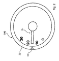
- FIG. 2 is a top view on a display surface of an instrument cluster of a vehicle according to an exemplary embodiment.
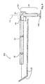
- FIG. 3 is a sectional view of the instrument cluster of a vehicle according to the exemplary embodiment.
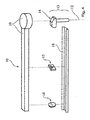
- FIG. 4 is an exploded view of the pointer of the instrument cluster according to the exemplary embodiment.
- FIG. 5 shows two top views according to different lighting conditions on a display surface of the instrument cluster of a vehicle according to the exemplary embodiment.
- the vehicle interior includes an instrument cluster 100 for providing information regarding vehicle parameters such as fuel level, vehicle speed, engine speed, engine temperature, etc.
- the vehicle interior usually also comprises a steering wheel (not shown) or another steering device ergonomically located so as to allow for a fatigue-proof usage by a driver or another user of the vehicle.
- FIG. 2 a pointer system or pointer device 10 for an instrument cluster 100 (or cluster) is shown together with a display surface 20 of the instrument cluster 100.
- FIG. 2 shows a top view of the instrument cluster 100.
- the pointer system 10 or pointing device 10 according to the present invention provides a projected light image 11.
- the projected light image 11 of the pointer system is shown in FIG. 2 on a left hand part of the instrument cluster 100 or cluster display surface 20.
- the display surface 20 is the surface which can be normally seen by the driver or user of the instrument cluster 100.
- a display graduation is schematically shown on the left hand side of the display surface 20 in the vicinity of the projected light image 11.
- the projected light image 11 By means of the projected light image 11 being in the vicinity of the graduation (or other symbolic indication on the display surface), it is possible for the driver to see the value of the vehicle parameter by means of the location of the projected light image 11.
- the projected light image 11 can have any form or shape, e.g. round, rectangular, triangular, elongated or the like. In the example shown in FIG. 2 , the projected light image 11 has a triangular shape (or an arrow like shape) such as to point to a certain part of the graduation in order to display the value of the vehicle parameter.
- FIG. 3 a sectional view of the instrument cluster 100 according to the exemplary embodiment is shown.
- the direction of view of FIG. 3 is parallel to the plane of the main extension of the display surface 20, i.e. substantially orthogonal to the direction of a rotational axis 12 of the pointing device 10.
- the pointing device 10 comprises a shaft element 13.
- the shaft element 13 extends substantially along the axis of rotation 12 of the pointer 10 or pointing device 10.
- the pointing device 10 comprises one of a light guiding element 14 or a mirror element.
- the light guiding element 14 can be provided such that a surface 14' serves as a mirror (where total reflection occurs).
- a mirror element (not shown), e.g. a metallized surface at the location of the surface 14', can be used in the context of the present invention.
- the one of the light guiding element 14 or the mirror element serves to direct light emitted by an LED 110 (emitting light which is incident to the shaft element 13 of the pointing device 10) towards one of an image forming element 15 or an aperture.
- the image forming element 15 is preferably provided as an image aperture. The image forming element 15 or image aperture moves together with the pointing device 10, i.e.
- the pointing device 10 also comprises a focusing element 16.
- the focusing element 16 also moves together with the pointing device 10, i.e. follows the rotational movement of the pointing device, i.e. of the shaft element 13. From the focusing element 16, the light is projected towards the display surface 20.
- the focusing element 16 is preferably provided as a focusing lens.
- the functions of the shaft element 13 and of the light guiding element 14 are integrated in the same element, i.e. the shaft is provided by a light guiding material and is preferably shaped such as to be able to guide the incident light (received from the LED 110 or from a plurality of LEDs (axially) behind the shaft element 13 of the pointing device 10) in a direction towards the image forming element 15.
- the one of the image forming element 15 or the aperture can also be integrated in the shaft element 13 of the pointing device 10 and/or in the one of the light guiding element 14 or mirror element.
- the focusing element 16 can also be integrated in the shaft element 13 of the pointing device 10 and/or in the one of the light guiding element 14 or mirror element.
- the focusing element 16 can also be integrated together with the one of the image forming element 15 or the image aperture. This integration can be provided such that the integrated focusing element and image forming element are provided (radially) spaced from the shaft element 13 or integrated in the shaft element 13 or near the shaft element 13 of the pointing device 10.
- FIG. 4 shows an exploded view of an exemplary embodiment of the pointing device 10 of the instrument cluster 100 according to the present invention.
- the pointing device 10 comprises, besides the shaft element 13 or pointer stem, a carrier 18 and a top shroud 19.
- the carrier 18 and the top shroud 19 extend substantially along the radial direction of the pointing device 10.
- the image forming element 15 or image aperture as well as the focusing element 16 or focusing lens are located.
- Both the carrier 18 and top shroud 19 serve to mechanically secure the focusing element 16 and the image forming element 15 with respect to the pointer shaft or shaft element 13 during the rotational movement of the pointing device 10 about the rotational axis 12, i.e. between different rotational positions of the pointing device 10 according to the present invention.
- the top shroud 19 is not backlit. This means that the top shroud 19 is only visible during daylight lighting conditions inside the vehicle and that the driver or user of the pointing device 10 does not or at least not precisely see the position of the pointer during nighttime lighting conditions, except by means of the projected image 11 visible on the display surface 20.
- FIG. 5 shows two top views according to different lighting conditions on a display surface 20 of the instrument cluster 100 according to the exemplary embodiment of the present invention.
- the pointing device 10 is not visible or at least not very well visible or at least not actively backlit with regard to the pointer stem or pointer shaft (shaft element 13) as well as with regard to the radial part of the pointing device 10 (i.e. the part of the pointer which extends along a substantially radial direction with respect to the rotational axis 12).
- the Image 11 (or projected image 11) of the image forming element 15 is projected on the display surface 20 such that the position of the pointing device 10 can easily be detected by a driver of the vehicle or a user of the instrument cluster 100.
- further light sources like further LEDs, are provided in the instrument cluster 100, especially behind at least a part of the display surface 20.
- the pointer stem or pointer shaft (shaft element 13) as well as the radial part of the pointing device 10 (i.e. the part of the pointing device 10 which extends along a substantially radial direction with respect to the rotational axis 12) is very well detectable such that the position of the pointing device 10 can easily be seen by the driver of the vehicle or the user of the instrument cluster.
- the projected image can always be lit, i.e. in both modes of operation of the instrument cluster, which means that the LED 110 emitting light towards the shaft element 13 is illuminated both during daytime mode of operation and during nighttime mode of operation.
- the projected image 11 can be lit only in the mode of operation of the instrument cluster relating to the nighttime appearance or during nighttime mode. In this alternative embodiment, it is possible to save energy that would otherwise be needed to illuminate the LED.
Landscapes
- Engineering & Computer Science (AREA)
- Chemical & Material Sciences (AREA)
- Combustion & Propulsion (AREA)
- Transportation (AREA)
- Mechanical Engineering (AREA)
- Physics & Mathematics (AREA)
- General Physics & Mathematics (AREA)
- Instrument Panels (AREA)
- Details Of Measuring Devices (AREA)
- Indicating Measured Values (AREA)
Abstract
Description
- The present disclosure relates generally to the field of display apparatus, and particularly to instrument clusters for cars and other vehicles. More specifically, this disclosure relates to the lighting of pointers inside of an instrument cluster of a vehicle.
- instrument clusters for vehicles often include an instrument panel that includes a pointer. The pointer is typically configured to point to some value of a vehicle parameter or other parameter such as fuel level, vehicle speed, preferred or preset vehicle speed, engine speed, engine temperature, time, etc. In many cases, the pointer can be rotated about a rotational axis and is in many cases connected to a stepper motor by means of a rotating shaft. The pointer generally comprises an axial portion extending substantially parallel to the rotational axis about which the pointer can be rotated. The pointer generally further comprises a radial portion extending substantially in a direction perpendicular to the axial portion and perpendicular to the rotational axis.
- it has become popular to light the pointer using light sources such as LEDs (light emitting diodes). In general, LEDs might be arranged around the outside of the shaft. As the pointer moves around the rotational axis, the pointer would be lit by subsequent LEDs around the shaft. Light from the LEDs would enter the pointer and make the pointer appear as if it were glowing. According to other solutions, one or a plurality of LEDs are located behind the center of the shaft such as to directly inject light into the shaft.
- With these current instrument cluster configurations, the pointer usually comprises a light guide element such that the light emitted by the LED or plurality of LEDs is guided by the light guide and directly emitted towards a user such that there is only one appearance of the pointer.
- There remains a continuing need to provide a more cost effective manufacture and assembly process of instrument cluster elements and to provide for an enhanced visibility of the pointer and the position of the pointer such that an enhanced clarity of the displayed information can be achieved.
- The present invention overcomes the disadvantages of the prior art by providing a design for a pointer or a pointer device for an instrument cluster of a car or other vehicle, wherein the pointing device is mounted rotatable about a rotation axis, wherein the pointing device has a shaft element in the vicinity of the rotation axis, wherein the pointing device further comprises at least one of a light guide element or a mirror element in the region of the shaft element, wherein the pointing device further comprises one of an image forming element or an aperture, wherein the one of the image forming element or the aperture and the one of the light guide element or the mirror element are able to be rotated about the rotational axis with the shaft element, and wherein light incident to the shaft element is directed from the one of the light guide element or the mirror element to the image forming element or aperture.
- With the pointing device according to the present invention, it is possible to provide a further pointing effect of the pointing device by the use of a projected image formed by the image forming element or the aperture, the image being reflected by a region of the appliqué of the instrument cluster towards the user of the pointing device.
- The pointing device according to the present invention comprises one of a light guide element or a mirror element in the region of the shaft of the pointer device. The light guide element preferably emits (or the mirror element reflects) light towards one of an image forming element or an aperture. The light emitted by the light guide element or reflected by the mirror element is projected (through the image forming element or aperture) to a part of the display surface visible to the driver of the vehicle or to the user of the instrument cluster. The display surface is preferably a formed appliqué surface of the instrument cluster according to the present invention.
- It is particularly preferred according to the present invention that light incident to the shaft element is visible to a user of the instrument cluster only after having passed one of the image forming element or the aperture and reflecting on the appliqué. It is particularly preferred that the projection of light to a part of the display surface is operational or visible to the driver of the vehicle or to the user of the instrument cluster only in certain lighting conditions, especially during night lighting conditions, i.e. reduced ambient lighting from the exterior of the vehicle, especially in the form of sunlight. Such reduced ambient lighting conditions are usually relevant during night time but also within tunnels or underbridges.
- Very preferably, the pointing device comprises one of a covering element or a shroud. This serves to prevent light incident to the shaft element from being reflected or otherwise ejected from the intended optical path within the pointing device so that light incident to the shaft element is prevented from being reflected in the direction to the driver or the user of the pointing device.
- According to a preferred embodiment of the present invention, the pointing device further comprises a focusing element, wherein the focusing element is able to be rotated about the rotational axis together with the shaft element, and wherein incident light is directed from the one of the image forming element or the aperture to the focusing element.
- By means of the focusing element, especially a focusing lens, the light emitted by the light guide element or reflected by the mirror element is projected (through the image forming element or aperture) to a part of the display surface visible to the driver of the vehicle or to the user of the instrument cluster. The display surface is preferably a formed appliqué surface of the instrument cluster according to the present invention.
- According to all embodiments of the present invention, it is preferred that the one of the light guide element or the mirror element is integrally formed with (or integrated in) the shaft element and/or that the one of the image forming element or the aperture is integrally formed with (or integrated in) the one of the light guide element or the mirror element and/or that the one of the image forming element or the aperture and the one of the light guide element or the mirror element are integrally formed with (or integrated in) the shaft element and/or that the focusing element is integrally formed with (or integrated in) the one of the image forming element or the aperture and/or that the focusing element and the one of the image forming element or the aperture are Integrally formed with (or Integrated In) the one of the light guide element or the mirror element.
- Such integrally forming (or integrating) of different elements of the pointing devices allows for a more simple construction of the pointing device and a less cost intensive construction and assembly of the pointing device.
- Another object of the present invention relates to an instrument cluster of a car or other vehicle, wherein the instrument cluster comprises a pointing device, wherein the pointing device is mounted rotatable about a rotational axis, wherein the pointing device has a shaft element in the vicinity of the rotation axis, wherein the pointing device further comprises at least one of a light guide element or a mirror element in the region of the shaft element, wherein the pointing device further comprises one of an image forming element or an aperture, wherein the one of the image forming element or the aperture and the one of the light guide element or the mirror element is able to be rotated about the rotational axis together with the shaft element, and wherein light incident to the shaft element is directed from the one of the light guide element or the mirror element to the image forming element or aperture.
- With the instrument cluster according to the present invention, it is possible to provide a further pointing effect of the pointing device by the use of a projected image formed by the image forming element or the aperture, the image being reflected by a region of the appliqué of the instrument cluster towards the user of the pointing device.
- It is preferred according to the present invention that the light incident to the shaft element is visible to a user of the instrument cluster only after having passed one of the image forming element or aperture and reflecting on the appliqué.
-
FIG. 1 is a perspective view of the interior of a vehicle having an instrument cluster schematically shown.. -
FIG. 2 is a top view on a display surface of an instrument cluster of a vehicle according to an exemplary embodiment. -
FIG. 3 is a sectional view of the instrument cluster of a vehicle according to the exemplary embodiment. -
FIG. 4 is an exploded view of the pointer of the instrument cluster according to the exemplary embodiment. -
FIG. 5 shows two top views according to different lighting conditions on a display surface of the instrument cluster of a vehicle according to the exemplary embodiment. - Referring generally to the figures and in particular to
FIG. 1 , a vehicle interior is partly shown according to an exemplary embodiment. The vehicle interior includes aninstrument cluster 100 for providing information regarding vehicle parameters such as fuel level, vehicle speed, engine speed, engine temperature, etc. Preferably, the vehicle interior usually also comprises a steering wheel (not shown) or another steering device ergonomically located so as to allow for a fatigue-proof usage by a driver or another user of the vehicle. - Referring to
FIG. 2 , a pointer system orpointer device 10 for an instrument cluster 100 (or cluster) is shown together with adisplay surface 20 of theinstrument cluster 100.FIG. 2 shows a top view of theinstrument cluster 100. Thepointer system 10 or pointingdevice 10 according to the present invention provides a projectedlight image 11. The projectedlight image 11 of the pointer system is shown inFIG. 2 on a left hand part of theinstrument cluster 100 orcluster display surface 20. Thedisplay surface 20 is the surface which can be normally seen by the driver or user of theinstrument cluster 100. InFIG. 2 , a display graduation is schematically shown on the left hand side of thedisplay surface 20 in the vicinity of the projectedlight image 11. By means of the projectedlight image 11 being in the vicinity of the graduation (or other symbolic indication on the display surface), it is possible for the driver to see the value of the vehicle parameter by means of the location of the projectedlight image 11. The projectedlight image 11 can have any form or shape, e.g. round, rectangular, triangular, elongated or the like. In the example shown inFIG. 2 , the projectedlight image 11 has a triangular shape (or an arrow like shape) such as to point to a certain part of the graduation in order to display the value of the vehicle parameter. - In
FIG. 3 , a sectional view of theinstrument cluster 100 according to the exemplary embodiment is shown. The direction of view ofFIG. 3 is parallel to the plane of the main extension of thedisplay surface 20, i.e. substantially orthogonal to the direction of arotational axis 12 of thepointing device 10. Thepointing device 10 comprises ashaft element 13. Theshaft element 13 extends substantially along the axis ofrotation 12 of thepointer 10 or pointingdevice 10. - Furthermore, the
pointing device 10 comprises one of alight guiding element 14 or a mirror element. The light guidingelement 14 can be provided such that a surface 14' serves as a mirror (where total reflection occurs). Alternatively, a mirror element (not shown), e.g. a metallized surface at the location of the surface 14', can be used in the context of the present invention. The one of thelight guiding element 14 or the mirror element serves to direct light emitted by an LED 110 (emitting light which is incident to theshaft element 13 of the pointing device 10) towards one of animage forming element 15 or an aperture. Theimage forming element 15 is preferably provided as an image aperture. Theimage forming element 15 or image aperture moves together with thepointing device 10, i.e. follows the rotational movement of the pointing device, i.e. of theshaft element 13. Preferably, thepointing device 10 also comprises a focusingelement 16. The focusingelement 16 also moves together with thepointing device 10, i.e. follows the rotational movement of the pointing device, i.e. of theshaft element 13. From the focusingelement 16, the light is projected towards thedisplay surface 20. According to all embodiments of the present invention, the focusingelement 16 is preferably provided as a focusing lens. - Preferably, the functions of the
shaft element 13 and of thelight guiding element 14 are integrated in the same element, i.e. the shaft is provided by a light guiding material and is preferably shaped such as to be able to guide the incident light (received from theLED 110 or from a plurality of LEDs (axially) behind theshaft element 13 of the pointing device 10) in a direction towards theimage forming element 15. - According to an alternative embodiment of the present invention, the one of the
image forming element 15 or the aperture can also be integrated in theshaft element 13 of thepointing device 10 and/or in the one of thelight guiding element 14 or mirror element. - According to a further alternative embodiment of the present invention, the focusing
element 16 can also be integrated in theshaft element 13 of thepointing device 10 and/or in the one of thelight guiding element 14 or mirror element. - According to still a further alternative embodiment of the present invention, the focusing
element 16 can also be integrated together with the one of theimage forming element 15 or the image aperture. This integration can be provided such that the integrated focusing element and image forming element are provided (radially) spaced from theshaft element 13 or integrated in theshaft element 13 or near theshaft element 13 of thepointing device 10. -
FIG. 4 shows an exploded view of an exemplary embodiment of thepointing device 10 of theinstrument cluster 100 according to the present invention. In this embodiment, thepointing device 10 comprises, besides theshaft element 13 or pointer stem, acarrier 18 and atop shroud 19. Thecarrier 18 and thetop shroud 19 extend substantially along the radial direction of thepointing device 10. Between thecarrier 18 and thetop shroud 19, theimage forming element 15 or image aperture as well as the focusingelement 16 or focusing lens are located. Both thecarrier 18 and top shroud 19 (or cover element) serve to mechanically secure the focusingelement 16 and theimage forming element 15 with respect to the pointer shaft orshaft element 13 during the rotational movement of thepointing device 10 about therotational axis 12, i.e. between different rotational positions of thepointing device 10 according to the present invention. - Preferably, the
top shroud 19 is not backlit. This means that thetop shroud 19 is only visible during daylight lighting conditions inside the vehicle and that the driver or user of thepointing device 10 does not or at least not precisely see the position of the pointer during nighttime lighting conditions, except by means of the projectedimage 11 visible on thedisplay surface 20. -
FIG. 5 shows two top views according to different lighting conditions on adisplay surface 20 of theinstrument cluster 100 according to the exemplary embodiment of the present invention. The appearance of theinstrument cluster 100 with thepointing device 10 according to the present invention which corresponds to daytime lighting conditions, i.e. illuminated lighting conditions, is shown on the left hand side ofFIG. 5 . The appearance of theinstrument cluster 100 with thepointing device 10 according to the present invention which corresponds to nighttime lighting conditions, i.e. non-illuminated lighting conditions, is shown on the right hand side ofFIG. 5 . From the nighttime appearance of the instrument cluster (right hand side ofFIG. 5 ), it can be seen that thepointing device 10 is not visible or at least not very well visible or at least not actively backlit with regard to the pointer stem or pointer shaft (shaft element 13) as well as with regard to the radial part of the pointing device 10 (i.e. the part of the pointer which extends along a substantially radial direction with respect to the rotational axis 12). However, from the nighttime appearance, it is visible that the Image 11 (or projected image 11) of theimage forming element 15 is projected on thedisplay surface 20 such that the position of thepointing device 10 can easily be detected by a driver of the vehicle or a user of theinstrument cluster 100. During nighttime appearance of thepointing device 10, there is preferably a backlit graphics visible on thedisplay surface 20. In order to realize such a backlit graphics, preferably further light sources, like further LEDs, are provided in theinstrument cluster 100, especially behind at least a part of thedisplay surface 20. From the daytime appearance, it can be seen fromFIG. 5 (cf. left hand side ofFigure 5 ) that the pointer stem or pointer shaft (shaft element 13) as well as the radial part of the pointing device 10 (i.e. the part of thepointing device 10 which extends along a substantially radial direction with respect to the rotational axis 12) is very well detectable such that the position of thepointing device 10 can easily be seen by the driver of the vehicle or the user of the instrument cluster. - According to an alternative embodiment of the present invention, the projected image can always be lit, i.e. in both modes of operation of the instrument cluster, which means that the
LED 110 emitting light towards theshaft element 13 is illuminated both during daytime mode of operation and during nighttime mode of operation. - According to another alternative embodiment of the present invention, the projected
image 11 can be lit only in the mode of operation of the instrument cluster relating to the nighttime appearance or during nighttime mode. In this alternative embodiment, it is possible to save energy that would otherwise be needed to illuminate the LED.
Claims (12)
- Pointing device for an instrument cluster of a car or other vehicle, wherein the pointing device is mounted rotatable about a rotation axis, wherein the pointing device has a shaft element in the vicinity of the rotation axis, wherein the pointing device further comprises at least one of a light guide element or a mirror element in the region of the shaft element, wherein the pointing device further comprises one of an image forming element or an aperture, wherein the one of the image forming element or the aperture and the one of the light guide element or the mirror element are able to be rotated about the rotational axis with the shaft element, and wherein light incident to the shaft element is directed from the one of the light guide element or the mirror element to the image forming element or aperture.
- Pointing device according to claim 1, wherein the pointing device further comprises a focusing element, wherein the focusing element is able to be rotated about the rotational axis together with the shaft element, and wherein incident light is directed from the one of the image forming element or the aperture to the focusing element.
- Pointing device according to claim 1, wherein the pointing device further comprises one of a covering element or a shroud.
- Pointing device according to claim 1, wherein light incident to the shaft element is visible to a user of the instrument cluster only after having passed one of the image forming element or aperture and reflecting on the appliqué.
- Pointing device according to claim 1, wherein the one of the light guide element or the mirror element is integrally formed with the shaft element.
- Pointing device according to claim 1, wherein the one of the image forming element or the aperture is integrally formed with the one of the light guide element or the mirror element.
- Pointing device according to claim 1, wherein the one of the image forming element or the aperture and the one of the light guide element or the mirror element are integrally formed with the shaft element.
- Pointing device according to claim 2, wherein the focusing element Is Integrally formed with the one of the image forming element or the aperture.
- Pointing device according to claim 2, wherein the focusing element and the one of the image forming element or the aperture are integrally formed with the one of the light guide element or the mirror element.
- Instrument cluster of a car or other vehicle, wherein the instrument cluster comprises a pointing device, wherein the pointing device is mounted rotatable about a rotational axis, wherein the pointing device has a shaft element in the vicinity of the rotation axis, wherein the pointing device further comprises at least one of a light guide element or a mirror element in the region of the shaft element, wherein the pointing device further comprises one of an image forming element or an aperture, wherein the one of the image forming element or the aperture and the one of the light guide element or the mirror element is able to be rotated about the rotational axis together with the shaft element, and wherein light incident to the shaft element is directed from the one of the light guide element or the mirror element to the image forming element or aperture.
- Instrument cluster according to claim 10, wherein the pointing device further comprises a focusing element, wherein the focusing element is able to be rotated about the rotational axis together with the shaft element, and wherein incident light is directed from the one of the image forming element or the aperture to the focusing element.
- instrument cluster according to claim 11, wherein light incident to the shaft element is visible to a user of the instrument cluster only through the one of the image forming element or the aperture.
Applications Claiming Priority (1)
| Application Number | Priority Date | Filing Date | Title |
|---|---|---|---|
| US12/692,743 US8579448B2 (en) | 2010-01-25 | 2010-01-25 | Pointer structure of an instrument cluster |
Publications (3)
| Publication Number | Publication Date |
|---|---|
| EP2348291A2 true EP2348291A2 (en) | 2011-07-27 |
| EP2348291A3 EP2348291A3 (en) | 2014-05-14 |
| EP2348291B1 EP2348291B1 (en) | 2016-11-02 |
Family
ID=44123273
Family Applications (1)
| Application Number | Title | Priority Date | Filing Date |
|---|---|---|---|
| EP11000267.2A Not-in-force EP2348291B1 (en) | 2010-01-25 | 2011-01-14 | Pointer structure of an instrument cluster |
Country Status (4)
| Country | Link |
|---|---|
| US (1) | US8579448B2 (en) |
| EP (1) | EP2348291B1 (en) |
| JP (2) | JP6116111B2 (en) |
| CN (1) | CN102145667B (en) |
Families Citing this family (9)
| Publication number | Priority date | Publication date | Assignee | Title |
|---|---|---|---|---|
| DE102007039327B4 (en) * | 2007-02-27 | 2017-08-31 | Johnson Controls Automotive Electronics Gmbh | Conically scaled indicating instrument for a motor vehicle and method for mounting a pointer instrument |
| FR2929702B1 (en) * | 2008-04-08 | 2015-05-22 | Johnson Controls Tech Co | DISPLAY DEVICE, IN PARTICULAR FOR A MOTOR VEHICLE, AND NEEDLE MOUNTING METHOD FOR A DISPLAY DEVICE |
| CN102642470B (en) * | 2011-10-15 | 2014-12-31 | 兰州吉利汽车工业有限公司 | Phantom-type combined automobile instrument |
| CN102514492B (en) * | 2011-11-22 | 2014-05-07 | 苏州科雷芯电子科技有限公司 | Vehicle dashboard based on visual technology of machine |
| US20150036315A1 (en) * | 2013-07-31 | 2015-02-05 | Delphi Technologies, Inc. | Instrument panel with illuminated pointer and trim ring |
| KR101490946B1 (en) | 2013-11-22 | 2015-02-06 | 현대자동차 주식회사 | Cluster havig shadow pointer |
| US10203229B2 (en) * | 2014-04-11 | 2019-02-12 | Continental Automotive Systems, Inc. | Pointerless instrument cluster gauge |
| DE102016202150A1 (en) * | 2016-02-12 | 2017-08-17 | Robert Bosch Gmbh | A display device and display device for a vehicle and method for producing a display device for a vehicle |
| CN106080196B (en) * | 2016-07-22 | 2018-04-10 | 北京汽车研究总院有限公司 | A kind of vehicle automatic controller and automobile |
Family Cites Families (54)
| Publication number | Priority date | Publication date | Assignee | Title |
|---|---|---|---|---|
| US2603129A (en) * | 1947-05-01 | 1952-07-15 | John F Dreyer | Dial indicator having polarizing elements |
| DE839104C (en) | 1950-03-11 | 1952-05-15 | Berthold Kirschner | Device for the static balancing of Flyer wings |
| JPS5813693Y2 (en) * | 1978-06-26 | 1983-03-17 | 日産自動車株式会社 | meter guideline |
| DE3149826A1 (en) | 1981-12-16 | 1983-07-21 | Robert Bosch Gmbh, 7000 Stuttgart | Inductive transmitter |
| US4628262A (en) * | 1985-02-05 | 1986-12-09 | Advanced Nmr Systems, Inc. | Multiple echo chemical shift imaging |
| US5130548A (en) * | 1988-02-03 | 1992-07-14 | Yazaki Corporation | Indicator |
| JPH02146319U (en) * | 1989-05-12 | 1990-12-12 | ||
| US5205635A (en) | 1990-07-05 | 1993-04-27 | Prince Corporation | Vehicle accessory body and integral circuit |
| FR2679988A1 (en) | 1991-07-30 | 1993-02-05 | Armines | METHOD FOR LIMITING THE FREEZING OF THE REFRIGERANT BATTERY OF AN OPEN REFRIGERATED FURNITURE AND FURNITURE USING THE SAME. |
| JP2575616Y2 (en) * | 1991-12-11 | 1998-07-02 | 矢崎総業株式会社 | Pointer device for vehicle instrument |
| DE4316998A1 (en) | 1993-05-21 | 1994-11-24 | Eaton Controls Gmbh | Electric push button switch |
| DE4321146A1 (en) | 1993-06-25 | 1995-01-05 | Vdo Schindling | Display unit |
| DE19544578B4 (en) | 1995-11-30 | 2012-06-06 | Continental Automotive Gmbh | pointer instrument |
| DE19624081A1 (en) * | 1996-06-17 | 1997-12-18 | Bosch Gmbh Robert | Pointer device |
| US5911492A (en) * | 1996-10-15 | 1999-06-15 | Delco Electronics Corporation | Metallized high intensity gauge pointer |
| DE19737679A1 (en) | 1997-08-29 | 1999-03-25 | Bosch Gmbh Robert | Indicating system e.g. for speed of motor vehicle with scale dial |
| DE19739628A1 (en) | 1997-09-10 | 1999-03-25 | Mannesmann Vdo Ag | Display instrument |
| US20020001183A1 (en) * | 1998-06-01 | 2002-01-03 | Ariyama Shigehiro | Surface emission light source device and method of manufacturing light guide plate with reflecting plate therefor |
| DE19831893C2 (en) | 1998-07-16 | 2002-10-10 | Draeger Safety Ag & Co Kgaa | Measuring device with a holder |
| DE19935386A1 (en) | 1999-07-29 | 2001-02-01 | Mannesmann Vdo Ag | Display with an X-ray display field |
| DE19956542A1 (en) | 1999-11-24 | 2001-05-31 | Mannesmann Vdo Ag | Display instrument for vehicle with LED and light conductive indicator fixedly connected to indicator shaft formed as light conductor |
| IT1317868B1 (en) * | 2000-03-02 | 2003-07-15 | Eni Spa | SUPPORTED COBALT CATALYST, PARTICULARLY USEFUL IN THE REACTION OF FISCHER-TROPSCH. |
| DE20021111U1 (en) | 2000-12-13 | 2001-03-01 | Festo AG & Co, 73734 Esslingen | Pressure display device |
| JP2003014508A (en) | 2001-07-04 | 2003-01-15 | Denso Corp | Vehicle instrument |
| DE10134365A1 (en) | 2001-07-14 | 2003-01-23 | Bosch Gmbh Robert | Instrument with pointer for use on dashboard of motor vehicle has arcuate slot controlling length of sliding pointer moving over non-circular calibrated scale |
| KR20040077668A (en) * | 2001-12-03 | 2004-09-06 | 지멘스 악티엔게젤샤프트 | Multiples detect apparatus and method |
| US6817310B2 (en) | 2001-12-26 | 2004-11-16 | Yazaki Corporation | Dial plate, its manufacturing method, meter using the same, in-vehicle status indicator and meter using the same |
| US6818291B2 (en) | 2002-08-17 | 2004-11-16 | 3M Innovative Properties Company | Durable transparent EMI shielding film |
| US6974220B2 (en) * | 2002-12-12 | 2005-12-13 | Siemens Vdo Automotive Corporation | Bright pointer for instrument cluster |
| US7221363B2 (en) | 2003-02-12 | 2007-05-22 | Gentex Corporation | Vehicle information displays |
| DE10322836A1 (en) | 2003-05-19 | 2004-12-23 | Siemens Ag | Incremental drive |
| US7098897B2 (en) | 2003-06-30 | 2006-08-29 | Motorola, Inc. | Touch screen assembly and display for an electronic device |
| US20050052426A1 (en) | 2003-09-08 | 2005-03-10 | Hagermoser E. Scott | Vehicle touch input device and methods of making same |
| US6981464B2 (en) * | 2003-11-19 | 2006-01-03 | Siemens Vdo Automotive Corporation | Illuminated pointer enabling independent pointing on two scales simultaneously |
| US20050134485A1 (en) | 2003-12-22 | 2005-06-23 | Hein David A. | Touch pad for motor vehicle and sensor therewith |
| JP4568087B2 (en) | 2004-01-28 | 2010-10-27 | 矢崎総業株式会社 | Vehicle display device |
| FR2871230B1 (en) | 2004-06-04 | 2006-09-01 | Johnson Controls Tech Co | INDICATOR DEVICE WITH ARTICULATED NEEDLE |
| FR2871563B1 (en) | 2004-06-11 | 2006-08-11 | Johnson Controls Tech Co | DASHBOARD INDICATOR WITH NEUTRAL FOLDER VISIBLE IN DIAL PERIPHERY AND INBOARD LIGHTING |
| WO2006002474A1 (en) | 2004-07-02 | 2006-01-12 | The Walter And Eliza Hall Institute Of Medical Research | Alpha-helical mimetics |
| US20060132383A1 (en) | 2004-09-27 | 2006-06-22 | Idc, Llc | System and method for illuminating interferometric modulator display |
| DE102005021317A1 (en) * | 2005-05-09 | 2006-11-16 | Siemens Ag | Indicating instrument for motor vehicle, has light and permeable covering provided between regions of flag parts, and light sources coupled by light over deflecting surfaces in respective small and large pointer flag parts |
| US7581342B2 (en) | 2005-08-24 | 2009-09-01 | Calsonic Kansei Corporation | Display device |
| DE102005055906A1 (en) | 2005-11-22 | 2007-05-31 | Borg Instruments Ag | Ring indicating instrument of a motor vehicle with a pointing position detection via bar code |
| US7798026B2 (en) * | 2006-01-11 | 2010-09-21 | Continental Automotive Systems Us, Inc. | Generated pointer image for an instrument cluster display |
| JP4993985B2 (en) | 2006-03-30 | 2012-08-08 | カルソニックカンセイ株式会社 | Variable display structure |
| WO2008063633A2 (en) * | 2006-11-20 | 2008-05-29 | Johnson Controls Technology Company | Instrument cluster |
| MX2009006563A (en) | 2007-01-05 | 2009-06-30 | Johnson Controls Tech Co | Multi-finish deep draw mold behind film. |
| JP4749354B2 (en) | 2007-02-06 | 2011-08-17 | 三菱自動車工業株式会社 | Touch switch structure |
| DE102007032851A1 (en) | 2007-02-07 | 2008-08-14 | Johnson Controls Automotive Electronics Gmbh | Motor vehicle indicating instrument with encompassing pointer |
| CN101809691B (en) | 2007-04-20 | 2012-07-18 | 英克-罗吉克斯有限公司 | In-molded capacitive switch |
| JP5034961B2 (en) * | 2008-01-11 | 2012-09-26 | 株式会社デンソー | Pointer instrument |
| JP5227618B2 (en) * | 2008-03-11 | 2013-07-03 | 矢崎総業株式会社 | Ultrasonic motor driven vehicle pointer instrument |
| US20110147051A1 (en) | 2008-06-10 | 2011-06-23 | Johnson Controls Technology Company | Capacitive switch sensors on decorative in-mold films background |
| US20110147181A1 (en) | 2008-08-26 | 2011-06-23 | Johnson Controls Technology Company | Three dimensional graphics with changing appearances |
-
2010
- 2010-01-25 US US12/692,743 patent/US8579448B2/en not_active Expired - Fee Related
-
2011
- 2011-01-14 EP EP11000267.2A patent/EP2348291B1/en not_active Not-in-force
- 2011-01-20 JP JP2011010074A patent/JP6116111B2/en active Active
- 2011-01-25 CN CN201110055966.1A patent/CN102145667B/en not_active Expired - Fee Related
-
2015
- 2015-04-15 JP JP2015082993A patent/JP6111281B2/en not_active Expired - Fee Related
Non-Patent Citations (1)
| Title |
|---|
| None |
Also Published As
| Publication number | Publication date |
|---|---|
| JP6116111B2 (en) | 2017-04-19 |
| EP2348291A3 (en) | 2014-05-14 |
| CN102145667A (en) | 2011-08-10 |
| JP6111281B2 (en) | 2017-04-05 |
| JP2015163891A (en) | 2015-09-10 |
| US20110182052A1 (en) | 2011-07-28 |
| CN102145667B (en) | 2015-12-02 |
| EP2348291B1 (en) | 2016-11-02 |
| US8579448B2 (en) | 2013-11-12 |
| JP2011180128A (en) | 2011-09-15 |
Similar Documents
| Publication | Publication Date | Title |
|---|---|---|
| EP2348291B1 (en) | Pointer structure of an instrument cluster | |
| CN102414541B (en) | Instrument lighting device | |
| JP5897097B2 (en) | Lighting ring in the pointer hub | |
| EP1977198B1 (en) | Generated pointer image for an instrument cluster display | |
| US8225736B2 (en) | Hub glow pointer | |
| EP2811264B1 (en) | Vehicular display apparatus | |
| JP5045403B2 (en) | Pointer instrument | |
| JP2006118892A (en) | Pointer instrument | |
| JP4826205B2 (en) | Pointer-type instrument | |
| JP4600234B2 (en) | Vehicle instrument | |
| JP5228254B2 (en) | Instrument device | |
| JP4655876B2 (en) | Vehicle indicator instrument | |
| JP2004144583A (en) | Luminescent pointer instrument | |
| JP5299408B2 (en) | Emission guidelines | |
| JP6026135B2 (en) | Pointer unit | |
| JP4062246B2 (en) | Pointer instrument | |
| JP2007033268A (en) | Vehicle indicator instrument | |
| EP2833103B1 (en) | Instrument panel with illuminated pointer and trim ring | |
| US20170241815A1 (en) | Indicating device with light-directing configuration | |
| JP2006017587A (en) | Pointer instrument | |
| US20140116321A1 (en) | Meter with pointer | |
| JP2006131209A (en) | VEHICLE DISPLAY DEVICE AND VEHICLE INSTRUMENT HAVING THE SAME | |
| JP2009192290A (en) | Pointer illumination structure | |
| JP2005351670A (en) | Indicating instrument | |
| JP2016024091A (en) | Fuel gauge for wheeled vehicles |
Legal Events
| Date | Code | Title | Description |
|---|---|---|---|
| PUAI | Public reference made under article 153(3) epc to a published international application that has entered the european phase |
Free format text: ORIGINAL CODE: 0009012 |
|
| AK | Designated contracting states |
Kind code of ref document: A2 Designated state(s): AL AT BE BG CH CY CZ DE DK EE ES FI FR GB GR HR HU IE IS IT LI LT LU LV MC MK MT NL NO PL PT RO RS SE SI SK SM TR |
|
| AX | Request for extension of the european patent |
Extension state: BA ME |
|
| PUAL | Search report despatched |
Free format text: ORIGINAL CODE: 0009013 |
|
| AK | Designated contracting states |
Kind code of ref document: A3 Designated state(s): AL AT BE BG CH CY CZ DE DK EE ES FI FR GB GR HR HU IE IS IT LI LT LU LV MC MK MT NL NO PL PT RO RS SE SI SK SM TR |
|
| AX | Request for extension of the european patent |
Extension state: BA ME |
|
| RIC1 | Information provided on ipc code assigned before grant |
Ipc: G01D 11/28 20060101AFI20140410BHEP |
|
| 17P | Request for examination filed |
Effective date: 20141114 |
|
| RBV | Designated contracting states (corrected) |
Designated state(s): AL AT BE BG CH CY CZ DE DK EE ES FI FR GB GR HR HU IE IS IT LI LT LU LV MC MK MT NL NO PL PT RO RS SE SI SK SM TR |
|
| 17Q | First examination report despatched |
Effective date: 20150410 |
|
| REG | Reference to a national code |
Ref country code: DE Ref legal event code: R079 Ref document number: 602011031795 Country of ref document: DE Free format text: PREVIOUS MAIN CLASS: G01D0011280000 Ipc: B60K0037020000 |
|
| GRAP | Despatch of communication of intention to grant a patent |
Free format text: ORIGINAL CODE: EPIDOSNIGR1 |
|
| RIC1 | Information provided on ipc code assigned before grant |
Ipc: G01D 11/28 20060101ALI20160415BHEP Ipc: B60K 37/02 20060101AFI20160415BHEP |
|
| INTG | Intention to grant announced |
Effective date: 20160523 |
|
| GRAS | Grant fee paid |
Free format text: ORIGINAL CODE: EPIDOSNIGR3 |
|
| GRAA | (expected) grant |
Free format text: ORIGINAL CODE: 0009210 |
|
| AK | Designated contracting states |
Kind code of ref document: B1 Designated state(s): AL AT BE BG CH CY CZ DE DK EE ES FI FR GB GR HR HU IE IS IT LI LT LU LV MC MK MT NL NO PL PT RO RS SE SI SK SM TR |
|
| REG | Reference to a national code |
Ref country code: GB Ref legal event code: FG4D |
|
| REG | Reference to a national code |
Ref country code: AT Ref legal event code: REF Ref document number: 841467 Country of ref document: AT Kind code of ref document: T Effective date: 20161115 Ref country code: CH Ref legal event code: EP |
|
| REG | Reference to a national code |
Ref country code: IE Ref legal event code: FG4D |
|
| REG | Reference to a national code |
Ref country code: DE Ref legal event code: R096 Ref document number: 602011031795 Country of ref document: DE |
|
| PG25 | Lapsed in a contracting state [announced via postgrant information from national office to epo] |
Ref country code: LV Free format text: LAPSE BECAUSE OF FAILURE TO SUBMIT A TRANSLATION OF THE DESCRIPTION OR TO PAY THE FEE WITHIN THE PRESCRIBED TIME-LIMIT Effective date: 20161102 |
|
| REG | Reference to a national code |
Ref country code: NL Ref legal event code: MP Effective date: 20161102 |
|
| REG | Reference to a national code |
Ref country code: LT Ref legal event code: MG4D |
|
| REG | Reference to a national code |
Ref country code: AT Ref legal event code: MK05 Ref document number: 841467 Country of ref document: AT Kind code of ref document: T Effective date: 20161102 |
|
| PG25 | Lapsed in a contracting state [announced via postgrant information from national office to epo] |
Ref country code: NL Free format text: LAPSE BECAUSE OF FAILURE TO SUBMIT A TRANSLATION OF THE DESCRIPTION OR TO PAY THE FEE WITHIN THE PRESCRIBED TIME-LIMIT Effective date: 20161102 Ref country code: LT Free format text: LAPSE BECAUSE OF FAILURE TO SUBMIT A TRANSLATION OF THE DESCRIPTION OR TO PAY THE FEE WITHIN THE PRESCRIBED TIME-LIMIT Effective date: 20161102 Ref country code: NO Free format text: LAPSE BECAUSE OF FAILURE TO SUBMIT A TRANSLATION OF THE DESCRIPTION OR TO PAY THE FEE WITHIN THE PRESCRIBED TIME-LIMIT Effective date: 20170202 Ref country code: SE Free format text: LAPSE BECAUSE OF FAILURE TO SUBMIT A TRANSLATION OF THE DESCRIPTION OR TO PAY THE FEE WITHIN THE PRESCRIBED TIME-LIMIT Effective date: 20161102 Ref country code: GR Free format text: LAPSE BECAUSE OF FAILURE TO SUBMIT A TRANSLATION OF THE DESCRIPTION OR TO PAY THE FEE WITHIN THE PRESCRIBED TIME-LIMIT Effective date: 20170203 |
|
| REG | Reference to a national code |
Ref country code: FR Ref legal event code: PLFP Year of fee payment: 7 |
|
| PG25 | Lapsed in a contracting state [announced via postgrant information from national office to epo] |
Ref country code: PT Free format text: LAPSE BECAUSE OF FAILURE TO SUBMIT A TRANSLATION OF THE DESCRIPTION OR TO PAY THE FEE WITHIN THE PRESCRIBED TIME-LIMIT Effective date: 20170302 Ref country code: AT Free format text: LAPSE BECAUSE OF FAILURE TO SUBMIT A TRANSLATION OF THE DESCRIPTION OR TO PAY THE FEE WITHIN THE PRESCRIBED TIME-LIMIT Effective date: 20161102 Ref country code: HR Free format text: LAPSE BECAUSE OF FAILURE TO SUBMIT A TRANSLATION OF THE DESCRIPTION OR TO PAY THE FEE WITHIN THE PRESCRIBED TIME-LIMIT Effective date: 20161102 Ref country code: PL Free format text: LAPSE BECAUSE OF FAILURE TO SUBMIT A TRANSLATION OF THE DESCRIPTION OR TO PAY THE FEE WITHIN THE PRESCRIBED TIME-LIMIT Effective date: 20161102 Ref country code: IS Free format text: LAPSE BECAUSE OF FAILURE TO SUBMIT A TRANSLATION OF THE DESCRIPTION OR TO PAY THE FEE WITHIN THE PRESCRIBED TIME-LIMIT Effective date: 20170302 Ref country code: FI Free format text: LAPSE BECAUSE OF FAILURE TO SUBMIT A TRANSLATION OF THE DESCRIPTION OR TO PAY THE FEE WITHIN THE PRESCRIBED TIME-LIMIT Effective date: 20161102 Ref country code: BE Free format text: LAPSE BECAUSE OF NON-PAYMENT OF DUE FEES Effective date: 20170131 Ref country code: ES Free format text: LAPSE BECAUSE OF FAILURE TO SUBMIT A TRANSLATION OF THE DESCRIPTION OR TO PAY THE FEE WITHIN THE PRESCRIBED TIME-LIMIT Effective date: 20161102 Ref country code: RS Free format text: LAPSE BECAUSE OF FAILURE TO SUBMIT A TRANSLATION OF THE DESCRIPTION OR TO PAY THE FEE WITHIN THE PRESCRIBED TIME-LIMIT Effective date: 20161102 |
|
| PG25 | Lapsed in a contracting state [announced via postgrant information from national office to epo] |
Ref country code: SK Free format text: LAPSE BECAUSE OF FAILURE TO SUBMIT A TRANSLATION OF THE DESCRIPTION OR TO PAY THE FEE WITHIN THE PRESCRIBED TIME-LIMIT Effective date: 20161102 Ref country code: DK Free format text: LAPSE BECAUSE OF FAILURE TO SUBMIT A TRANSLATION OF THE DESCRIPTION OR TO PAY THE FEE WITHIN THE PRESCRIBED TIME-LIMIT Effective date: 20161102 Ref country code: CZ Free format text: LAPSE BECAUSE OF FAILURE TO SUBMIT A TRANSLATION OF THE DESCRIPTION OR TO PAY THE FEE WITHIN THE PRESCRIBED TIME-LIMIT Effective date: 20161102 Ref country code: RO Free format text: LAPSE BECAUSE OF FAILURE TO SUBMIT A TRANSLATION OF THE DESCRIPTION OR TO PAY THE FEE WITHIN THE PRESCRIBED TIME-LIMIT Effective date: 20161102 Ref country code: EE Free format text: LAPSE BECAUSE OF FAILURE TO SUBMIT A TRANSLATION OF THE DESCRIPTION OR TO PAY THE FEE WITHIN THE PRESCRIBED TIME-LIMIT Effective date: 20161102 |
|
| REG | Reference to a national code |
Ref country code: DE Ref legal event code: R097 Ref document number: 602011031795 Country of ref document: DE |
|
| RAP2 | Party data changed (patent owner data changed or rights of a patent transferred) |
Owner name: JOHNSON CONTROLS TECHNOLOGY COMPANY |
|
| PG25 | Lapsed in a contracting state [announced via postgrant information from national office to epo] |
Ref country code: BE Free format text: LAPSE BECAUSE OF FAILURE TO SUBMIT A TRANSLATION OF THE DESCRIPTION OR TO PAY THE FEE WITHIN THE PRESCRIBED TIME-LIMIT Effective date: 20161102 Ref country code: SM Free format text: LAPSE BECAUSE OF FAILURE TO SUBMIT A TRANSLATION OF THE DESCRIPTION OR TO PAY THE FEE WITHIN THE PRESCRIBED TIME-LIMIT Effective date: 20161102 Ref country code: IT Free format text: LAPSE BECAUSE OF FAILURE TO SUBMIT A TRANSLATION OF THE DESCRIPTION OR TO PAY THE FEE WITHIN THE PRESCRIBED TIME-LIMIT Effective date: 20161102 Ref country code: BG Free format text: LAPSE BECAUSE OF FAILURE TO SUBMIT A TRANSLATION OF THE DESCRIPTION OR TO PAY THE FEE WITHIN THE PRESCRIBED TIME-LIMIT Effective date: 20170202 |
|
| REG | Reference to a national code |
Ref country code: CH Ref legal event code: PL |
|
| PLBE | No opposition filed within time limit |
Free format text: ORIGINAL CODE: 0009261 |
|
| STAA | Information on the status of an ep patent application or granted ep patent |
Free format text: STATUS: NO OPPOSITION FILED WITHIN TIME LIMIT |
|
| PG25 | Lapsed in a contracting state [announced via postgrant information from national office to epo] |
Ref country code: MC Free format text: LAPSE BECAUSE OF FAILURE TO SUBMIT A TRANSLATION OF THE DESCRIPTION OR TO PAY THE FEE WITHIN THE PRESCRIBED TIME-LIMIT Effective date: 20161102 |
|
| 26N | No opposition filed |
Effective date: 20170803 |
|
| GBPC | Gb: european patent ceased through non-payment of renewal fee |
Effective date: 20170202 |
|
| PG25 | Lapsed in a contracting state [announced via postgrant information from national office to epo] |
Ref country code: LI Free format text: LAPSE BECAUSE OF NON-PAYMENT OF DUE FEES Effective date: 20170131 Ref country code: CH Free format text: LAPSE BECAUSE OF NON-PAYMENT OF DUE FEES Effective date: 20170131 |
|
| REG | Reference to a national code |
Ref country code: IE Ref legal event code: MM4A |
|
| PG25 | Lapsed in a contracting state [announced via postgrant information from national office to epo] |
Ref country code: LU Free format text: LAPSE BECAUSE OF NON-PAYMENT OF DUE FEES Effective date: 20170114 Ref country code: SI Free format text: LAPSE BECAUSE OF FAILURE TO SUBMIT A TRANSLATION OF THE DESCRIPTION OR TO PAY THE FEE WITHIN THE PRESCRIBED TIME-LIMIT Effective date: 20161102 |
|
| REG | Reference to a national code |
Ref country code: FR Ref legal event code: PLFP Year of fee payment: 8 |
|
| PG25 | Lapsed in a contracting state [announced via postgrant information from national office to epo] |
Ref country code: GB Free format text: LAPSE BECAUSE OF NON-PAYMENT OF DUE FEES Effective date: 20170202 Ref country code: IE Free format text: LAPSE BECAUSE OF NON-PAYMENT OF DUE FEES Effective date: 20170114 |
|
| PGFP | Annual fee paid to national office [announced via postgrant information from national office to epo] |
Ref country code: DE Payment date: 20180219 Year of fee payment: 8 |
|
| PGFP | Annual fee paid to national office [announced via postgrant information from national office to epo] |
Ref country code: FR Payment date: 20180130 Year of fee payment: 8 |
|
| PG25 | Lapsed in a contracting state [announced via postgrant information from national office to epo] |
Ref country code: MT Free format text: LAPSE BECAUSE OF NON-PAYMENT OF DUE FEES Effective date: 20170114 |
|
| REG | Reference to a national code |
Ref country code: DE Ref legal event code: R082 Ref document number: 602011031795 Country of ref document: DE Representative=s name: KUTZENBERGER WOLFF & PARTNER PATENTANWALTSPART, DE Ref country code: DE Ref legal event code: R081 Ref document number: 602011031795 Country of ref document: DE Owner name: VISTEON GLOBAL TECHNOLOGIES INC., VAN BUREN, US Free format text: FORMER OWNER: JOHNSON CONTROLS TECHNOLOGY COMPANY, HOLLAND, MICH., US |
|
| PG25 | Lapsed in a contracting state [announced via postgrant information from national office to epo] |
Ref country code: HU Free format text: LAPSE BECAUSE OF FAILURE TO SUBMIT A TRANSLATION OF THE DESCRIPTION OR TO PAY THE FEE WITHIN THE PRESCRIBED TIME-LIMIT; INVALID AB INITIO Effective date: 20110114 |
|
| REG | Reference to a national code |
Ref country code: DE Ref legal event code: R119 Ref document number: 602011031795 Country of ref document: DE |
|
| PG25 | Lapsed in a contracting state [announced via postgrant information from national office to epo] |
Ref country code: CY Free format text: LAPSE BECAUSE OF NON-PAYMENT OF DUE FEES Effective date: 20161102 Ref country code: DE Free format text: LAPSE BECAUSE OF NON-PAYMENT OF DUE FEES Effective date: 20190801 Ref country code: FR Free format text: LAPSE BECAUSE OF NON-PAYMENT OF DUE FEES Effective date: 20190131 |
|
| PG25 | Lapsed in a contracting state [announced via postgrant information from national office to epo] |
Ref country code: MK Free format text: LAPSE BECAUSE OF FAILURE TO SUBMIT A TRANSLATION OF THE DESCRIPTION OR TO PAY THE FEE WITHIN THE PRESCRIBED TIME-LIMIT Effective date: 20161102 |
|
| PG25 | Lapsed in a contracting state [announced via postgrant information from national office to epo] |
Ref country code: TR Free format text: LAPSE BECAUSE OF FAILURE TO SUBMIT A TRANSLATION OF THE DESCRIPTION OR TO PAY THE FEE WITHIN THE PRESCRIBED TIME-LIMIT Effective date: 20161102 |
|
| PG25 | Lapsed in a contracting state [announced via postgrant information from national office to epo] |
Ref country code: AL Free format text: LAPSE BECAUSE OF FAILURE TO SUBMIT A TRANSLATION OF THE DESCRIPTION OR TO PAY THE FEE WITHIN THE PRESCRIBED TIME-LIMIT Effective date: 20161102 |