EP2348287A2 - Displacement measuring apparatus and velocity measuring apparatus - Google Patents
Displacement measuring apparatus and velocity measuring apparatus Download PDFInfo
- Publication number
- EP2348287A2 EP2348287A2 EP11151592A EP11151592A EP2348287A2 EP 2348287 A2 EP2348287 A2 EP 2348287A2 EP 11151592 A EP11151592 A EP 11151592A EP 11151592 A EP11151592 A EP 11151592A EP 2348287 A2 EP2348287 A2 EP 2348287A2
- Authority
- EP
- European Patent Office
- Prior art keywords
- moving object
- measuring apparatus
- light emitting
- emitting area
- photo diode
- Prior art date
- Legal status (The legal status is an assumption and is not a legal conclusion. Google has not performed a legal analysis and makes no representation as to the accuracy of the status listed.)
- Withdrawn
Links
- 238000006073 displacement reaction Methods 0.000 title claims abstract description 79
- 238000007373 indentation Methods 0.000 claims abstract description 45
- 230000004907 flux Effects 0.000 claims abstract description 11
- 238000005259 measurement Methods 0.000 claims abstract description 8
- 230000003287 optical effect Effects 0.000 claims description 28
- 230000000737 periodic effect Effects 0.000 claims 1
- 238000003491 array Methods 0.000 description 27
- 238000001514 detection method Methods 0.000 description 22
- 239000011295 pitch Substances 0.000 description 18
- 238000010586 diagram Methods 0.000 description 15
- 238000000034 method Methods 0.000 description 14
- 238000003384 imaging method Methods 0.000 description 5
- 230000015572 biosynthetic process Effects 0.000 description 4
- 230000001427 coherent effect Effects 0.000 description 3
- 230000003321 amplification Effects 0.000 description 2
- 230000003247 decreasing effect Effects 0.000 description 2
- 230000001678 irradiating effect Effects 0.000 description 2
- 238000010137 moulding (plastic) Methods 0.000 description 2
- 238000003199 nucleic acid amplification method Methods 0.000 description 2
- 230000008569 process Effects 0.000 description 2
- 230000008859 change Effects 0.000 description 1
- 230000001934 delay Effects 0.000 description 1
- 230000003111 delayed effect Effects 0.000 description 1
- 230000000694 effects Effects 0.000 description 1
- 230000006872 improvement Effects 0.000 description 1
- 238000012986 modification Methods 0.000 description 1
- 230000004048 modification Effects 0.000 description 1
- 239000000758 substrate Substances 0.000 description 1
- 230000036962 time dependent Effects 0.000 description 1
Images





Classifications
-
- G—PHYSICS
- G01—MEASURING; TESTING
- G01D—MEASURING NOT SPECIALLY ADAPTED FOR A SPECIFIC VARIABLE; ARRANGEMENTS FOR MEASURING TWO OR MORE VARIABLES NOT COVERED IN A SINGLE OTHER SUBCLASS; TARIFF METERING APPARATUS; MEASURING OR TESTING NOT OTHERWISE PROVIDED FOR
- G01D5/00—Mechanical means for transferring the output of a sensing member; Means for converting the output of a sensing member to another variable where the form or nature of the sensing member does not constrain the means for converting; Transducers not specially adapted for a specific variable
- G01D5/26—Mechanical means for transferring the output of a sensing member; Means for converting the output of a sensing member to another variable where the form or nature of the sensing member does not constrain the means for converting; Transducers not specially adapted for a specific variable characterised by optical transfer means, i.e. using infrared, visible, or ultraviolet light
- G01D5/28—Mechanical means for transferring the output of a sensing member; Means for converting the output of a sensing member to another variable where the form or nature of the sensing member does not constrain the means for converting; Transducers not specially adapted for a specific variable characterised by optical transfer means, i.e. using infrared, visible, or ultraviolet light with deflection of beams of light, e.g. for direct optical indication
- G01D5/30—Mechanical means for transferring the output of a sensing member; Means for converting the output of a sensing member to another variable where the form or nature of the sensing member does not constrain the means for converting; Transducers not specially adapted for a specific variable characterised by optical transfer means, i.e. using infrared, visible, or ultraviolet light with deflection of beams of light, e.g. for direct optical indication the beams of light being detected by photocells
-
- G—PHYSICS
- G01—MEASURING; TESTING
- G01P—MEASURING LINEAR OR ANGULAR SPEED, ACCELERATION, DECELERATION, OR SHOCK; INDICATING PRESENCE, ABSENCE, OR DIRECTION, OF MOVEMENT
- G01P3/00—Measuring linear or angular speed; Measuring differences of linear or angular speeds
- G01P3/36—Devices characterised by the use of optical means, e.g. using infrared, visible, or ultraviolet light
-
- G—PHYSICS
- G01—MEASURING; TESTING
- G01B—MEASURING LENGTH, THICKNESS OR SIMILAR LINEAR DIMENSIONS; MEASURING ANGLES; MEASURING AREAS; MEASURING IRREGULARITIES OF SURFACES OR CONTOURS
- G01B11/00—Measuring arrangements characterised by the use of optical techniques
-
- G—PHYSICS
- G01—MEASURING; TESTING
- G01P—MEASURING LINEAR OR ANGULAR SPEED, ACCELERATION, DECELERATION, OR SHOCK; INDICATING PRESENCE, ABSENCE, OR DIRECTION, OF MOVEMENT
- G01P3/00—Measuring linear or angular speed; Measuring differences of linear or angular speeds
- G01P3/64—Devices characterised by the determination of the time taken to traverse a fixed distance
- G01P3/68—Devices characterised by the determination of the time taken to traverse a fixed distance using optical means, i.e. using infrared, visible, or ultraviolet light
Definitions
- the present invention relates to a displacement measuring apparatus and a velocity measuring apparatus which perform noncontact measurements of a displacement amount and a velocity, respectively.
- the apparatuses may be used in the measurements of moving objects made, for example, by plastic molding.
- the shapes of the moving objects, that are the result of such plastic molding, may thus be exploited by the present invention to measure displacement and velocity of the moving object.
- One is a method of irradiating coherent light onto the moving object to generate a speckle pattern caused by a complex interference of luminous flux that is obtained by the reflection and the divergence of the light to detect a displacement or a velocity of the moving object based on a movement of the speckle pattern in accordance with a movement of the moving object.
- the other is a method of irradiating coherent light beams at incident angles different from each other with respect to the moving object to obtain a velocity of the moving object based on a difference between optical frequency Doppler shifts that are received at the time of the reflection and the divergence.
- Japanese Patent Laid-Open No. 58-113762 discloses a method of using an incoherent light source to detect a displacement amount and a velocity of an imaged object.
- the present invention in its first aspect provides a displacement measuring apparatus as specified in claims 1 to 5.
- the present invention in its second aspect provides a velocity measuring apparatus as specified in claim 6.
- Fig. 1 is a schematic configuration diagram of a displacement measuring apparatus in Embodiment 1.
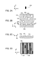
- Figs. 2A to 2D are explanatory diagrams of a principle of generating a light emitting area image in a displacement measuring apparatus in Embodiment 1.
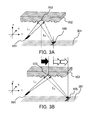
- Figs. 3A and 3B are diagrams illustrating a relationship between a movement amount of a moving object and a movement amount of a light emitting area image in Embodiment 1.
- Fig. 4 is a diagram illustrating indentations that are periodically arranged on a surface of a moving object in Embodiment 1.
- Fig. 5 is a schematic configuration diagram of a displacement measuring apparatus in Embodiment 2.
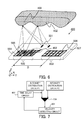
- Fig. 6 is a schematic configuration diagram of a velocity measuring apparatus in Embodiment 3.
- Fig. 7 is a block diagram of a process that provides data with a time delay in Embodiment 3.
- Fig. 8 is a schematic configuration diagram of another velocity measuring apparatus 400a in Embodiment 3.
- Fig. 9 is a schematic configuration diagram of another velocity measuring apparatus 400b in Embodiment 3.
- Fig. 1 is a schematic configuration diagram of the displacement measuring apparatus in the present embodiment.
- reference numeral 100 denotes a displacement measuring apparatus which measures a displacement amount of a moving object.
- Reference numeral 101 denotes a light emitting area 101 of a light source that is provided in the displacement measuring apparatus 100.
- the moving object is irradiated by using luminous flux emitted from the light emitting area 101.
- the light emitting area 101 indicates a light emitting pattern formed by a mask such as an opening that is formed in a laminated electrode on a light emitting surface of a bare chip LED (light emitting diode).
- the light emitting area 101 also includes a light emitting surface of a surface light emitting light source such as a VCSEL or a light emitting surface of an LD of around 1 ⁇ m to 2 ⁇ m.
- Reference numeral 102 denotes a moving object.
- the moving object 102 is a measurement target of a displacement amount performed by the displacement measuring apparatus 100.
- the moving object 102 is capable of moving in a Y direction, and is irradiated by divergent light from the light emitting area 101 of the light source.
- the divergent light irradiated on the moving object 102 is reflected and converged on indentations (or concave portions of the surface) 103 of the moving object 102 to form a light source area image 106 on photo diode arrays 104 and 105 (a light receiving element).
- the light receiving element includes a plurality of light receiving areas (e.g.
- the displacement measuring apparatus 100 includes a measurement unit (not shown) that measures the displacement amount of the moving object 102 based on a movement amount of the light emitting area image 106 formed on the light receiving element by imaging the luminous flux reflected from the indentations 103.
- the indentations 103 are concave and have a focal length F that meets the following Expression (1), where L1 is an optical path length from a light emitting point on the light emitting area 101 of the light source to the indentation 103, L2 is an optical path length from the indentation 103 to the photo diode arrays 104 and 105 and F is a negative focal length because the object point and image point are on the same side of the indentation in the object.
- - 1 / L ⁇ 1 - 1 / L ⁇ 2 1 / F
- the photo diode arrays 104 and 105 are alternately arranged with a width Pd/2 and a pitch Pd (a period width) in the movement direction (the Y direction) of the moving object 102.
- the photo diode arrays 104 and 105 have the same configuration and are spatially displaced each other by the width Pd/2 in the movement direction of the moving object 102.
- a width We of the light emitting area 101 is determined by linking the width of each of the photo diode arrays 104 and 105. The details will be described below.
- a principle of generating the light emitting area image 106 in the displacement measuring apparatus 100 will be described. First of all, a position where the light emitting area image 106 is generated will be described. Divergent light that is emitted from the light source including the light emitting area 101 illustrated in Fig. 2A is reflected and converged on each of the indentations 103 on the surface of the moving object 102 illustrated in Fig. 2B . Therefore, as illustrated in Fig.
- the light emitting area image 106 of the light source is formed on the surfaces of the photo diode arrays 104 and 105 with a position relation corresponding to a position of each of the indentations 103 on a surface of the moving object 102.
- the indentations 103 having a variety of shapes are distributed.
- a width of each of the indentations 103 is different from each other as illustrated in Fig. 2C that is A-A cross section of Fig. 2B .
- the indentations 103 having a variety of shapes exist.
- the light receiving portion surface (the photo diode arrays 104 and 105) is arranged at an optimal observation position that is determined by a shape of the indentation 103 of the moving object 102, the light emitting area image 106 is formed in some cases. This is a case in which the indentation 103 has a focal length F that meets Expression (1) above.
- a shape of the indentation 103 which has a diameter of around 100 ⁇ m and a depth that is equal to or smaller than around 2 ⁇ m contributes to the formation of the light emitting area image 106.
- a shape of the indentation 103 which has a diameter of around 200 ⁇ m and a depth of around a few ⁇ m contributes to the formation of the light emitting area image 106.
- the area in the indentation 103 which contributes to the formation of the image is different in accordance with the observation position. Therefore, when the indentation 103 has a curved complex shape as described above, the light emitting area image 106 is formed even if the distance between the light receiving portion surface and the moving object 102 is changed to some extent.
- the size of the light emitting area image 106 that is to be formed will be described.
- the indentation 103 has the focal length F which meets Expression (1)
- the light emitting area image 106 is formed on the photo diode arrays 104 and 105.
- the indentation 103 does not have an ideal curved surface, and has a plurality of curved complex shapes in many cases.
- the light emitting area image 106 is formed by overlapping a light emitting area image that is formed on the indentation 103 having the focal length F which meets Expression (1) with a plurality of light emitting area images that are defocused by the plurality of curved complex shapes.
- the light emitting area image 106 that is formed on the photo diode arrays 104 and 105 has a width of around one and a half times to twice as wide as the width of the light emitting area 101 where an image is ideally formed.
- the width of the light emitting area image 106 is equal to the width of each of the photo diode arrays 104 and 105, detection with high light use efficiency can be performed.
- the formed light emitting area image 106 crosses the width Pd/2 of each of the photo diode arrays 104 and 105, and the light emitting area image 106 spreads out or overlaps to adjacent photo diode arrays 104 and 105. Therefore, according to a principle of a signal detection described below, detected signal amplitude is decreased, and velocity detection accuracy is deteriorated.
- reference symbol We is defined as a width of the light emitting area 101 of the light source in the movement direction (the Y direction) of the moving object 102.
- We/Pd - that is, a ratio of the light emitting area width We of the light source and a photo diode array pitch Pd - is equal to or greater than 0.87 due to the above phenomenon, the size of the image on the light receiving surface in the movement direction is equal to or greater than a width of the photo diode array pitch.
- We/Pd is equal to or less than 0.87.
- the light emitting area 101 of the light source is too small, the light emitting area image does not overlap into the adjacent photo diode array.
- the value of We/Pd is smaller than 0.275, a problem may be caused in which the detected signal amplitude is decreased by ten percent or more to deteriorate determination accuracy of the displacement amount of the moving object because of the decrease of a detected light intensity caused by the shrinkage of the light emitting area. Accordingly, in order to obtain the displacement detection accuracy, it is preferable that a condition that is represented by the following Expression (2) is met. 0.275 ⁇ We / Pd ⁇ 0.87
- Figs. 3A and 3B indicate a relationship between a movement amount of the moving object 102 and a moving amount of the light emitting area image 106 on the photo diode array surface 301.
- Fig. 3A is a position relation between the moving object 102 and the light emitting area image 106 at a time T1
- Fig. 3B is a position relation between the moving object 102 and the light emitting area image 106 at a time T2.
- a black arrow in Fig. 3B indicates a moving amount of the moving object 102 in a time difference T2-T1
- white arrows in Fig. 3B indicate a moving amount of the light emitting area image 106 on the photo diode array surface 301 in the time difference T2-T1.
- the light emitting area image 106 formed on the photo diode array surface 301 moves in accordance with the movement of the moving object 102.
- the light emitting area image 106 is formed on the photo diode arrays 104 and 105 by the indentations 103 of the moving object 1 0 2 .
- a two-dimensional optical pattern image comprising the light emitting area image 106 generated on the photo diode arrays 104 and 105 is photoelectrically converted by the photo diode arrays 104 and 105 to be converted into a voltage value indicating a one-dimensional light intensity.
- a sum of the detected voltage values of a plurality of photo diodes that constitute the photo diode array 104 is obtained, and a detected voltage value V1 of the photo diode array 104 is determined in combination with a spatial filter function.
- a sum of the detected voltage values of a plurality of photo diodes that constitute the photo diode array 105 is obtained, and a detected voltage value V2 of the photo diode array 105 is determined in combination with the spatial filter function.
- the displacement measuring apparatus 100 outputs a difference V1-V2 of the detected voltage values of both the photo diode arrays 104 and 105, i.e. a differential of the outputs of the photo diode arrays 104 and 105, as a voltage value at a predetermined time.
- Va-Vb a positive voltage
- the difference V1-V2 of the detected voltage value is nearly equal to Vb-Va ((V1-V2) (Vb-Va) ⁇ 0).
- the displacement amount of the moving object 102 can be detected.
- a configuration of a differential detection photo diode array is adopted in order to increase the amplitude of the detected signal, but the configuration of the displacement measuring photo diode array is not limited to this.
- the displacement amount may also be detected based on a situation where a one-dimensional intensity distribution of the optical pattern image is displaced on the array.
- the differential amplification does not have to be performed using the differential photo diode array 105.
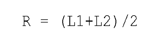
- the indentations 103 are discretely or continuously provided on the moving object 102, and is preferably a shape including a radius of curvature that meets the following Expression (3), where R is a radius of curvature of the indentation 103.
- R L ⁇ 1 + L ⁇ 2 / 2
- the displacement amount of the moving object 102 may also be detected using the periodical light emitting area image 106a that is formed on the photo diode arrays 104 and 105.
- FIG. 5 is a schematic configuration diagram of a displacement measuring apparatus 100a in the present embodiment.
- the displacement measuring apparatus 100a of the present embodiment is different from the displacement measuring apparatus 100 of Embodiment 1 in that a plurality of light emitting areas 401 (even numbers of light emitting areas) are arranged in the light source at a pitch Pe.
- a change of a light emitting area image 402 and an influence on a detected signal caused by providing the plurality of light emitting areas 401 will be described.
- a light emitting area image that is formed by one indentation 103 is formed at the same magnification as the original light emitting area image 401.
- a plurality of light sources may be provided to be able to generate images with predetermined pitches in a random optical pattern image.
- the pitch Pe of the formed light emitting area images 402 is aligned with the pitch Pd of the photo diode arrays 104 and 105 to be able to effectively obtain an effect as a spatial filter of the photo diode arrays 104 and 105 arranged spatially with the pitch.
- the light emitting area images 402 have the periodicity of the light emitting areas and have the same period as a photo diode array period of image detection, resulting in an increase of the detected signal amplitude and an improvement of the displacement detection.
- the imaging magnification of the plurality of light emitting area images 402 may be changed to displace the pitch of the light emitting area images of the plurality of light emitting area images 402 from the predetermined pitch Pe.
- the signal amplitude is decayed and an error of the velocity detection accuracy is increased. If the displacement amount is large, the detected voltage values of the photo diode arrays 104 and 105 may be equal to each other and the signal cannot be obtained by the differential of the detected voltage value of each photo diode array in some cases.
- the pitch Pe of the light emitting area images 402 and the pitch Pd of the photo diode arrays 104 and 105 meet the following Expression (5).
- N is an integer equal to or greater than 2 and indicates the number of the light emitting areas.
- the present embodiment describes an embodiment with two light emitting areas, but is not limited to this as long as Expression (5) described above is met.
- the light emitting areas have only to be arranged so as to include a period of integral multiple of the pitch Pe of the light emitting area images 402 which meets Expression (5). Since a principle of detecting the displacement amount is similar to that of Embodiment 1, the description in the embodiment is omitted.
- the configuration of the differential detection photo diode array is adopted in order to increase the amplitude of the detected signal, and similarly to Embodiment 1, the configuration of the displacement measuring photo diode is not limited to this.
- the displacement amount may also be detected based on a situation where the one-dimensional intensity distribution of the optical pattern image is being displaced on the array.
- the differential amplification does not have to be performed using the differential photo diode array 105.
- the indentation 103 of the moving object 102 is not only limited to a hemispherical shape, but also a shape may be adopted in which an indentation that is a (semi-)cylindrical surface and is periodically formed on purpose as illustrated in Fig. 4 .
- Fig. 6 is a schematic configuration diagram of a velocity measuring apparatus 400 in the present embodiment.
- the velocity measuring apparatus 400 is configured so as to detect the velocity of the moving object 102 based on a displacement amount of the moving object 102 in a predetermined time or a time needed for the moving object to pass a predetermined distance.
- the velocity measuring apparatus 400 includes a plurality of light emitting areas 501 and photo diode array groups 502 and 503.
- the photo diode array group 502 includes a photo diode array 504 and a photo diode array 505 that are used for performing differential detection.
- the photo diode array group 503 includes a photo diode array 506 and a photo diode array 507 that are also used for performing differential detection.
- the photo diode array groups 502 and 503 are disposed with their centers separated by a distance D.
- a two-dimensional optical pattern image constituted of a plurality of light emitting area images 402 that is generated on each photo diode array group is photoelectrically converted by the photo diode array, and a one-dimensional light intensity is converted into a voltage value.
- a detected voltage value V1 of the photo diode array 504 is determined.
- a detected voltage value V2 of the photo diode array 505 is determined.
- the photo diode array group 502 outputs a difference V1-V2 of the detected voltage values as a voltage value at a predetermined time.
- the photo diode array group 503 outputs a voltage value at a predetermined time.
- a method of detecting the velocity will be described.
- a case in which the moving object 102 moves in a Y-axis direction is considered.
- a displacement signal in accordance with the movement of the optical pattern image is detected by the photo diode array group 502.
- the displacement signal in accordance with the movement of the optical pattern image at the same position is delayed by a time that depends upon the distance D between the photo diode array groups 502 and 503 in the Y-axis direction and the velocity of the moving object 102 to be detected by the photo diode array group 503.
- T of the same signal detected by each photo diode array group is precisely obtained, the velocity of the moving object 102 can be calculated as D is known (and velocity is of course distance over time; D/T).
- Fig. 7 is a block diagram of a process that provides data with a time delay.
- Variation data (intensity distribution data) of the detected output in accordance with the movement of the moving object 102 in a predetermined time, which is previously detected by the photo diode array group 502, is defined as P1.
- variation data (intensity distribution data) of the detected output, which is detected by the photo diode array group 503 with delays in accordance with the movement of the moving object 102 in the predetermined time is defined as P2.
- the variation data P1 and P2 are compared by a comparator 508, which compares voltage values with respect to a time.
- a velocity detecting circuit 601 provides a time delay circuit 602 with a correction value with respect to the time delay amount.
- the correction value is determined as follows. Using the photodiode array group 502 and 503, detection of the time-based light intensity data P1 and P2 is performed as mentioned above.
- One of the outputs e.g.
- the velocity detecting circuit 601 determines the detection time difference T. Furthermore, based on the distance D between the photo diode array groups 502 and 503, a velocity V of the moving object 102 can be obtained by using the following Expression (6).
- V D T ⁇ L ⁇ 1 L ⁇ 1 + L ⁇ 2
- the present embodiment describes an example where the velocity measuring apparatus 400 is configured by using the displacement measuring apparatus 100a in Embodiment 2.
- the present embodiment is not limited to this, and the velocity measuring apparatus 400 may also be configured by using the displacement measuring apparatus 100 of Embodiment 1.
- the configuration of the photo diode array as described in Embodiments 1 and 2, it is not limited to the configuration of the differential detection photo diode array.
- Fig. 8 is a schematic configuration diagram of another velocity measuring apparatus 400a in the present embodiment.
- the velocity measuring apparatus 400a is configured so that the photo diode array groups 502 and 503 are nested.
- the distance D between the photo diode array groups 502 and 503 is set so as to be shorter than a length of each photo diode array.
- Photodiode array groups 502 and 503 work in the same way as photodiode array groups 104 and 105 above. The difference is that photodiode array group 502, which is equivalent to group 104, has spaces between each photodiode of the array and these spaces are the width of a single photodiode.
- the two groups are overlapped so that photodiode types 506 and 507 from group 503 are interspersed between photodiode types 504 and 505 of the group 502.
- the distance D is the same as the width of a photodiode, and less than the length of the photodiode array, which is effective for detecting high frequency velocity variation.
- Fig. 9 is a schematic configuration diagram of another velocity measuring apparatus 400b in the present embodiment.
- the photo diode array groups 502 and 503 are not disposed on the same substrate, and the two displacement measuring apparatus described in Embodiments 1 and 2 may also be disposed at a predetermined distance D from each other.
Landscapes
- Physics & Mathematics (AREA)
- General Physics & Mathematics (AREA)
- Engineering & Computer Science (AREA)
- Electromagnetism (AREA)
- Power Engineering (AREA)
- Length Measuring Devices By Optical Means (AREA)
- Optical Transform (AREA)
Abstract
A displacement measuring apparatus (100) which measures a displacement amount of a moving object (102) includes a light source that irradiates the moving object (102) using luminous flux emitted from a light emitting area (101), a photo diode array (104, 105) that includes a plurality of light receiving areas in a movement direction of the moving object (102) and that forms an image of the luminous flux reflected on a plurality of indentations (103) of the moving object (102) to receive light, and a measurement unit that measures the displacement amount of the moving object (102) based on a movement amount of a light emitting area image (106) that is formed on the photo diode array (104, 105) by forming the image of the luminous flux.
Description
- The present invention relates to a displacement measuring apparatus and a velocity measuring apparatus which perform noncontact measurements of a displacement amount and a velocity, respectively. The apparatuses may be used in the measurements of moving objects made, for example, by plastic molding. The shapes of the moving objects, that are the result of such plastic molding, may thus be exploited by the present invention to measure displacement and velocity of the moving object.
- As a method of performing noncontact detection of a displacement amount of a moving object, the following two methods are known. One is a method of irradiating coherent light onto the moving object to generate a speckle pattern caused by a complex interference of luminous flux that is obtained by the reflection and the divergence of the light to detect a displacement or a velocity of the moving object based on a movement of the speckle pattern in accordance with a movement of the moving object. The other is a method of irradiating coherent light beams at incident angles different from each other with respect to the moving object to obtain a velocity of the moving object based on a difference between optical frequency Doppler shifts that are received at the time of the reflection and the divergence. However, in the methods described above, there is a problem of low reliability of an LD (laser diode) or a VCSEL (vertical cavity surface emitting laser) used as a coherent light source, high cost caused by the complexity of the configuration of an apparatus, or the like. Therefore, Japanese Patent Laid-Open No.
58-113762 - However, in the velocity measuring apparatus disclosed in Japanese Patent Laid-Open No.
58-113762 - It is desirable to provide highly accurate displacement measuring apparatus and velocity measuring apparatus.
- The present invention in its first aspect provides a displacement measuring apparatus as specified in
claims 1 to 5. - The present invention in its second aspect provides a velocity measuring apparatus as specified in claim 6.
- Further features and aspects of the present invention will become apparent from the following description of embodiments with reference to the attached drawings.
-
Fig. 1 is a schematic configuration diagram of a displacement measuring apparatus inEmbodiment 1. -
Figs. 2A to 2D are explanatory diagrams of a principle of generating a light emitting area image in a displacement measuring apparatus inEmbodiment 1. -
Figs. 3A and 3B are diagrams illustrating a relationship between a movement amount of a moving object and a movement amount of a light emitting area image inEmbodiment 1. -
Fig. 4 is a diagram illustrating indentations that are periodically arranged on a surface of a moving object inEmbodiment 1. -
Fig. 5 is a schematic configuration diagram of a displacement measuring apparatus in Embodiment 2. -
Fig. 6 is a schematic configuration diagram of a velocity measuring apparatus in Embodiment 3. -
Fig. 7 is a block diagram of a process that provides data with a time delay in Embodiment 3. -
Fig. 8 is a schematic configuration diagram of anothervelocity measuring apparatus 400a in Embodiment 3. -
Fig. 9 is a schematic configuration diagram of anothervelocity measuring apparatus 400b in Embodiment 3. - Exemplary embodiments of the present invention will be described below with reference to the accompanied drawings. In each of the drawings, the same elements will be denoted by the same reference numerals and the duplicate descriptions thereof will be omitted.
- First of all, a displacement measuring apparatus in
Embodiment 1 of the present invention will be described.Fig. 1 is a schematic configuration diagram of the displacement measuring apparatus in the present embodiment. InFig. 1 ,reference numeral 100 denotes a displacement measuring apparatus which measures a displacement amount of a moving object.Reference numeral 101 denotes alight emitting area 101 of a light source that is provided in thedisplacement measuring apparatus 100. The moving object is irradiated by using luminous flux emitted from thelight emitting area 101. Thelight emitting area 101 indicates a light emitting pattern formed by a mask such as an opening that is formed in a laminated electrode on a light emitting surface of a bare chip LED (light emitting diode). Thelight emitting area 101 also includes a light emitting surface of a surface light emitting light source such as a VCSEL or a light emitting surface of an LD of around 1µm to 2µm. -
Reference numeral 102 denotes a moving object. Themoving object 102 is a measurement target of a displacement amount performed by thedisplacement measuring apparatus 100. Themoving object 102 is capable of moving in a Y direction, and is irradiated by divergent light from thelight emitting area 101 of the light source. The divergent light irradiated on themoving object 102 is reflected and converged on indentations (or concave portions of the surface) 103 of themoving object 102 to form a lightsource area image 106 onphoto diode arrays 104 and 105 (a light receiving element). As illustrated inFig. 1 , the light receiving element includes a plurality of light receiving areas (e.g. a plurality ofphoto diode arrays 104 and 105) arranged in a movement direction (the Y direction) of themoving object 102, and forms an image of luminous flux reflected from theconcave indentations 103 of themoving object 102 to receive the luminous flux. Thedisplacement measuring apparatus 100 includes a measurement unit (not shown) that measures the displacement amount of themoving object 102 based on a movement amount of the lightemitting area image 106 formed on the light receiving element by imaging the luminous flux reflected from theindentations 103. - It is preferable that the
indentations 103 are concave and have a focal length F that meets the following Expression (1), where L1 is an optical path length from a light emitting point on thelight emitting area 101 of the light source to theindentation 103, L2 is an optical path length from theindentation 103 to thephoto diode arrays 
- The
photo diode arrays moving object 102. Thephoto diode arrays moving object 102. A width We of thelight emitting area 101 is determined by linking the width of each of thephoto diode arrays - Next, referring to
Figs. 2A to 2D , a principle of generating the lightemitting area image 106 in thedisplacement measuring apparatus 100 will be described. First of all, a position where the lightemitting area image 106 is generated will be described. Divergent light that is emitted from the light source including thelight emitting area 101 illustrated inFig. 2A is reflected and converged on each of theindentations 103 on the surface of themoving object 102 illustrated inFig. 2B . Therefore, as illustrated inFig. 2D , the lightemitting area image 106 of the light source is formed on the surfaces of thephoto diode arrays indentations 103 on a surface of themoving object 102. - Next, a shape of the
indentation 103 of themoving object 102 and a phenomenon of the formation of the lightemitting area image 106 will be described. On a surface of a common object, as illustrated inFig. 2B , theindentations 103 having a variety of shapes are distributed. A width of each of theindentations 103 is different from each other as illustrated inFig. 2C that is A-A cross section ofFig. 2B . Thus, theindentations 103 having a variety of shapes exist. However, when the light receiving portion surface (thephoto diode arrays 104 and 105) is arranged at an optimal observation position that is determined by a shape of theindentation 103 of the movingobject 102, the light emittingarea image 106 is formed in some cases. This is a case in which theindentation 103 has a focal length F that meets Expression (1) above. - For example, in an area where a distance between the displacement measuring apparatus 100 (the light receiving portion surface) and the moving
object 102 is around 1 to 3mm, a shape of theindentation 103 which has a diameter of around 100µm and a depth that is equal to or smaller than around 2µm contributes to the formation of the light emittingarea image 106. Additionally, in an area where a distance between the light receiving portion surface and the movingobject 102 is around 4 to 6mm, a shape of theindentation 103 which has a diameter of around 200µm and a depth of around a few µm contributes to the formation of the light emittingarea image 106. Thus, the area in theindentation 103 which contributes to the formation of the image is different in accordance with the observation position. Therefore, when theindentation 103 has a curved complex shape as described above, the light emittingarea image 106 is formed even if the distance between the light receiving portion surface and the movingobject 102 is changed to some extent. - Next, the size of the light emitting
area image 106 that is to be formed will be described. As described above, when theindentation 103 has the focal length F which meets Expression (1), the light emittingarea image 106 is formed on thephoto diode arrays indentation 103 does not have an ideal curved surface, and has a plurality of curved complex shapes in many cases. In this case, the light emittingarea image 106 is formed by overlapping a light emitting area image that is formed on theindentation 103 having the focal length F which meets Expression (1) with a plurality of light emitting area images that are defocused by the plurality of curved complex shapes. Due to such a phenomenon, the light emittingarea image 106 that is formed on thephoto diode arrays light emitting area 101 where an image is ideally formed. - Fundamentally, if the width of the light emitting
area image 106 is equal to the width of each of thephoto diode arrays area image 106 crosses the width Pd/2 of each of thephoto diode arrays area image 106 spreads out or overlaps to adjacentphoto diode arrays light emitting area 101 of the light source in the movement direction (the Y direction) of the movingobject 102. When We/Pd - that is, a ratio of the light emitting area width We of the light source and a photo diode array pitch Pd - is equal to or greater than 0.87 due to the above phenomenon, the size of the image on the light receiving surface in the movement direction is equal to or greater than a width of the photo diode array pitch. As a result, since the detection signal amplitude with respect to a displacement of the moving object is lowered by ten percent or more, there is a problem that the determination accuracy of the displacement is deteriorated. Accordingly, it is preferable that We/Pd is equal to or less than 0.87. - Conversely, if the
light emitting area 101 of the light source is too small, the light emitting area image does not overlap into the adjacent photo diode array. However, when the value of We/Pd is smaller than 0.275, a problem may be caused in which the detected signal amplitude is decreased by ten percent or more to deteriorate determination accuracy of the displacement amount of the moving object because of the decrease of a detected light intensity caused by the shrinkage of the light emitting area. Accordingly, in order to obtain the displacement detection accuracy, it is preferable that a condition that is represented by the following Expression (2) is met.
- Next, referring to
Figs. 3A and 3B , a displacement principle of the light emittingarea image 106 will be described.Figs. 3A and 3B indicate a relationship between a movement amount of the movingobject 102 and a moving amount of the light emittingarea image 106 on the photodiode array surface 301.Fig. 3A is a position relation between the movingobject 102 and the light emittingarea image 106 at a time T1, andFig. 3B is a position relation between the movingobject 102 and the light emittingarea image 106 at a time T2. A black arrow inFig. 3B indicates a moving amount of the movingobject 102 in a time difference T2-T1, and white arrows inFig. 3B indicate a moving amount of the light emittingarea image 106 on the photodiode array surface 301 in the time difference T2-T1. - The relationship between the movement amount (i.e. displacement) of the moving
object 102 and the movement amount (i.e. displacement) of the light emittingarea image 106 is represented as follows:
- In the present embodiment, the optical path length L1 from a light emitting point on the
light emitting area 101 of the light source to a surface (the indentation 103) of the movingobject 102 and the optical path length L2 from the surface of the movingobject 102 to thephoto diode array 104 that is a light receiving element are equal to each other. Therefore, the relationship between the movement amount of the movingobject 102 and the movement amount of the light emittingarea image 106 is as follows.
- Based on the above principle, the light emitting
area image 106 formed on the photodiode array surface 301 moves in accordance with the movement of the movingobject 102. - Next, referring back to
Fig. 1 , a method of detecting the displacement amount of the movingobject 102 will be described in detail. First of all, a configuration of the photo diode array and a signal detecting method will be described. The light emittingarea image 106 is formed on thephoto diode arrays indentations 103 of the movingobject 1 0 2 . A two-dimensional optical pattern image comprising the light emittingarea image 106 generated on thephoto diode arrays photo diode arrays photo diode array 104 is obtained, and a detected voltage value V1 of thephoto diode array 104 is determined in combination with a spatial filter function. Similarly, a sum of the detected voltage values of a plurality of photo diodes that constitute thephoto diode array 105 is obtained, and a detected voltage value V2 of thephoto diode array 105 is determined in combination with the spatial filter function. Then, thedisplacement measuring apparatus 100 outputs a difference V1-V2 of the detected voltage values of both thephoto diode arrays photo diode arrays - Next, a method of detecting the displacement amount of the moving
object 102 based on movements of the optical pattern images on thephoto diode arrays object 102 will be described. In the embodiment, a case in which the detected voltage values V1 and V2 of thedisplacement measuring apparatus 100 are equal to Va and Vb, respectively, and the difference V1-V2 of the detected voltage values is equal to Va-Vb that is a positive voltage ((V1-V2)=(Va-Vb)>0) is considered. In this case, when the optical pattern image is moved by Pd/2, a phase of the intensity distribution is reversed by 180 degrees and the sign of the detected voltage value is reversed to be negative. In other words, the difference V1-V2 of the detected voltage value is nearly equal to Vb-Va ((V1-V2)(Vb-Va)<0).
- When the optical pattern image is further moved by Pd/2, i.e. one period of pitches of the
photo diode arrays Vb-Va>0 is met. Thus, when the optical pattern image is moved by the pitch Pd (the displacement amount) on the
photo diode arrays object 102, the number of the periods of output voltage changes that are detected by thedisplacement measuring apparatus 100 is counted to be able to detect a movement amount of the optical pattern image on thephoto diode arrays object 102 and the light emittingarea image 106 described above and the movement amount of the detected optical pattern image, as described referring toFigs. 3A and 3B , the displacement amount of the movingobject 102 can be detected. - In the present embodiment, a configuration of a differential detection photo diode array is adopted in order to increase the amplitude of the detected signal, but the configuration of the displacement measuring photo diode array is not limited to this. For example, using a photo diode array, the displacement amount may also be detected based on a situation where a one-dimensional intensity distribution of the optical pattern image is displaced on the array. In the embodiment, the differential amplification does not have to be performed using the differential
photo diode array 105. - The
indentations 103 are discretely or continuously provided on the movingobject 102, and is preferably a shape including a radius of curvature that meets the following Expression (3), where R is a radius of curvature of theindentation 103.
- The
indentation 103 included in the movingobject 102 is not only limited to a hemispherical shape, but also a (semi-) cylindrical surface may be adopted. Furthermore, as illustrated inFig. 4 , theconcave shape 103a may be periodically formed on the movingobject 102 on purpose. In this case, an array period Pl meets the following Expression (4), where k is a positive integer.
- Thus, the displacement amount of the moving
object 102 may also be detected using the periodical light emittingarea image 106a that is formed on thephoto diode arrays - Next, Embodiment 2 of the present invention will be described.
Fig. 5 is a schematic configuration diagram of adisplacement measuring apparatus 100a in the present embodiment. Thedisplacement measuring apparatus 100a of the present embodiment is different from thedisplacement measuring apparatus 100 ofEmbodiment 1 in that a plurality of light emitting areas 401 (even numbers of light emitting areas) are arranged in the light source at a pitch Pe. In the present embodiment, a change of a light emittingarea image 402 and an influence on a detected signal caused by providing the plurality oflight emitting areas 401 will be described. - For example, when the optical path length L1 is equal to the optical path length L2 (L1=L2), a light emitting area image that is formed by one
indentation 103 is formed at the same magnification as the original light emittingarea image 401. The original light emittingarea image 401 contains plural light emitting areas with a pitch Pe, and so a plurality of light emittingarea images 402 also having the pitch Pe are formed when L1=L2. This occurs when the luminous fluxes emitted from the plurality oflight emitting areas 401 are reflected from one indentation in the moving object and are imaged on the receiving element with a pitch Pe. This occurs even when the moving object has a non-periodical set of indentations on its surface. Thus, a plurality of light sources may be provided to be able to generate images with predetermined pitches in a random optical pattern image. The pitch Pe of the formed light emittingarea images 402 is aligned with the pitch Pd of thephoto diode arrays photo diode arrays indentations 103 have a random period, the light emittingarea images 402 have the periodicity of the light emitting areas and have the same period as a photo diode array period of image detection, resulting in an increase of the detected signal amplitude and an improvement of the displacement detection. - In accordance with a mounting accuracy of the light source or the photo diode array in a Z-axis direction, the imaging magnification of the plurality of light emitting
area images 402 may be changed to displace the pitch of the light emitting area images of the plurality of light emittingarea images 402 from the predetermined pitch Pe. In this case, the signal amplitude is decayed and an error of the velocity detection accuracy is increased. If the displacement amount is large, the detected voltage values of thephoto diode arrays area images 402 and the pitch Pd of thephoto diode arrays 
area images 402 which meets Expression (5). Since a principle of detecting the displacement amount is similar to that ofEmbodiment 1, the description in the embodiment is omitted. - In the present embodiment, the configuration of the differential detection photo diode array is adopted in order to increase the amplitude of the detected signal, and similarly to
Embodiment 1, the configuration of the displacement measuring photo diode is not limited to this. For example, using the photo diode array, the displacement amount may also be detected based on a situation where the one-dimensional intensity distribution of the optical pattern image is being displaced on the array. In the embodiment, the differential amplification does not have to be performed using the differentialphoto diode array 105. Theindentation 103 of the movingobject 102 is not only limited to a hemispherical shape, but also a shape may be adopted in which an indentation that is a (semi-)cylindrical surface and is periodically formed on purpose as illustrated inFig. 4 . - Next, Embodiment 3 of the present invention will be described. In the present embodiment, a method of measuring a velocity of the moving
object 102 using thedisplacement measuring apparatus 100 ofEmbodiment 1 or thedisplacement measuring apparatus 100a of Embodiment 2 will be described.Fig. 6 is a schematic configuration diagram of avelocity measuring apparatus 400 in the present embodiment. Thevelocity measuring apparatus 400 is configured so as to detect the velocity of the movingobject 102 based on a displacement amount of the movingobject 102 in a predetermined time or a time needed for the moving object to pass a predetermined distance. - The
velocity measuring apparatus 400 includes a plurality oflight emitting areas 501 and photodiode array groups diode array group 502 includes aphoto diode array 504 and aphoto diode array 505 that are used for performing differential detection. The photodiode array group 503 includes aphoto diode array 506 and aphoto diode array 507 that are also used for performing differential detection. The photodiode array groups area images 402 that is generated on each photo diode array group is photoelectrically converted by the photo diode array, and a one-dimensional light intensity is converted into a voltage value. Then, as a sum of the detected voltage values of a plurality of photo diodes constituting thephoto diode array 504, a detected voltage value V1 of thephoto diode array 504 is determined. Similarly, as a sum of the detected voltage values of a plurality of photo diodes constituting thephoto diode array 505, a detected voltage value V2 of thephoto diode array 505 is determined. Then, the photodiode array group 502 outputs a difference V1-V2 of the detected voltage values as a voltage value at a predetermined time. Similarly, the photodiode array group 503 outputs a voltage value at a predetermined time. - Next, a method of detecting the velocity will be described. In the embodiment, a case in which the moving
object 102 moves in a Y-axis direction is considered. In this case, first, a displacement signal in accordance with the movement of the optical pattern image is detected by the photodiode array group 502. Subsequently, the displacement signal in accordance with the movement of the optical pattern image at the same position is delayed by a time that depends upon the distance D between the photodiode array groups object 102 to be detected by the photodiode array group 503. If a detection time difference T of the same signal detected by each photo diode array group is precisely obtained, the velocity of the movingobject 102 can be calculated as D is known (and velocity is of course distance over time; D/T). - Next, referring to
Fig. 7 , the method of detecting the velocity will be specifically described.Fig. 7 is a block diagram of a process that provides data with a time delay. Variation data (intensity distribution data) of the detected output in accordance with the movement of the movingobject 102 in a predetermined time, which is previously detected by the photodiode array group 502, is defined as P1. Similarly, variation data (intensity distribution data) of the detected output, which is detected by the photodiode array group 503 with delays in accordance with the movement of the movingobject 102 in the predetermined time, is defined as P2. The variation data P1 and P2 are compared by acomparator 508, which compares voltage values with respect to a time. - If an optimum time delay amount of data is provided to the variation data P1, as a result of the comparison by the
comparator 508, the variation data outputs P1 and P2 of respective photo diode array groups coincide with each other with respect to a time. On the other hand, if the variation data outputs P1 and P2 do not coincide with each other, avelocity detecting circuit 601 provides atime delay circuit 602 with a correction value with respect to the time delay amount. The correction value is determined as follows. Using thephotodiode array group photodiode array groups comparator 508 performs the comparison again using the variation data P1 to which the corrected time delay amount has been provided. In accordance with the loop, thevelocity detecting circuit 601 determines the detection time difference T. Furthermore, based on the distance D between the photodiode array groups object 102 can be obtained by using the following Expression (6).
- The present embodiment describes an example where the
velocity measuring apparatus 400 is configured by using thedisplacement measuring apparatus 100a in Embodiment 2. However, the present embodiment is not limited to this, and thevelocity measuring apparatus 400 may also be configured by using thedisplacement measuring apparatus 100 ofEmbodiment 1. With respect to the configuration of the photo diode array, as described inEmbodiments 1 and 2, it is not limited to the configuration of the differential detection photo diode array. -
Fig. 8 is a schematic configuration diagram of anothervelocity measuring apparatus 400a in the present embodiment. As illustrated inFig. 8 , thevelocity measuring apparatus 400a is configured so that the photodiode array groups diode array groups Photodiode array groups photodiode array groups photodiode array group 502, which is equivalent togroup 104, has spaces between each photodiode of the array and these spaces are the width of a single photodiode. Inphotodiode array groups photodiode types group 503 are interspersed betweenphotodiode types group 502. In this case, the distance D is the same as the width of a photodiode, and less than the length of the photodiode array, which is effective for detecting high frequency velocity variation. -
Fig. 9 is a schematic configuration diagram of anothervelocity measuring apparatus 400b in the present embodiment. As illustrated inFig. 9 , the photodiode array groups Embodiments 1 and 2 may also be disposed at a predetermined distance D from each other. In this case, a velocity calculation formula is obtained by V=D/T based on a time T needed for passing a distance D between centers of the photo diode groups in the displacement measuring apparatus. - According to each of the above embodiments, using the light emitting area image that is formed on the light receiving element surface (on the photo diode) by the indentation of the moving object, it is able to obtain a clear optical pattern image. Thus, a displacement detection signal of the moving object which has a good SN ratio as signal integrity is obtained, and as a result, detection accuracy of a displacement amount and a velocity can be improved. Since a detection system does not use an imaging system such as a lens, the size, the weight, and the cost can be reduced. Therefore, a high accurate displacement measuring apparatus can be provided.
- While the present invention has been described with reference to exemplary embodiments, it is to be understood that the invention is not limited to the disclosed exemplary embodiments. The scope of the following claims is to be accorded the broadest interpretation so as to encompass all such modifications and equivalent structures and functions.
Claims (6)
- A displacement measuring apparatus (100) for measuring a displacement amount of a moving object (102), the displacement measuring apparatus comprising:a light source configured to irradiate the moving object using luminous flux emitted from a light emitting area (101);a light receiving element including a plurality of light receiving areas (104, 105) arranged in a movement direction of the moving object, the light receiving element being arranged such that luminous flux that is emitted from the light emitting area (101) and that is reflected from indentations (103) in the moving object are imaged on a light receiving surface of the light receiving element; anda measurement unit configured to measure the displacement amount of the moving object based on a movement amount of a light emitting area image (106) that is formed on the light receiving element.
- The displacement measuring apparatus (100) according to claim 1 that meets the following condition, where We is a width of the light emitting area (101) in the movement direction of the moving object, and Pd is a pitch between light receiving areas (104, 105) adjacent to each other in the movement direction of the moving object:

- The displacement measuring apparatus (100) according to claim 1,
wherein the light source includes an even number of light emitting areas arranged in the movement direction of the moving object, and
wherein the displacement measuring apparatus meets the following condition, where L1 is an optical path length from a light emitting point of the light source to one of the plurality of indentations of the moving object, L2 is an optical path length from the same indentation of the moving object to the light receiving element, Pe is a pitch between light receiving areas (104, 105) arranged adjacent to each other in the movement direction of the moving object, and N is the number of light emitting areas and is an even number:
- The displacement measuring apparatus (100) according to any one of claims 1 to 3, configured to receive light from and measure the displacement amount of a moving object having indentations that are discretely or continuously provided on the moving object and have a shape including a radius of curvature which meets the following condition, where R is the radius of curvature of one of the plurality of indentations, L1 is an optical path length from a light emitting point of the light source to the indentation of the moving object, and L2 is an optical path length from the indentation of the moving object to the light receiving element.
- The displacement measuring apparatus (100) according to any one of claims 1 to 4, configured to receive light from and measure the displacement amount of a moving object having indentations that are in a periodic array so as to meet the following condition, where Pl is an array period of the indentations (103), Pd is a pitch between light receiving areas (104, 105) arranged adjacent to each other in the movement direction of the moving object, and k is a positive integer.

- A velocity measuring apparatus including the displacement measuring apparatus according to any one of claims 1 to 5,
wherein the velocity measuring apparatus is arranged to detect a velocity of the moving object based on the displacement amount of the moving object determined by the displacement measuring apparatus in a predetermined time.
Applications Claiming Priority (1)
| Application Number | Priority Date | Filing Date | Title |
|---|---|---|---|
| JP2010012471A JP5460352B2 (en) | 2010-01-22 | 2010-01-22 | Displacement measuring device and velocity measuring device |
Publications (1)
| Publication Number | Publication Date |
|---|---|
| EP2348287A2 true EP2348287A2 (en) | 2011-07-27 |
Family
ID=44063677
Family Applications (1)
| Application Number | Title | Priority Date | Filing Date |
|---|---|---|---|
| EP11151592A Withdrawn EP2348287A2 (en) | 2010-01-22 | 2011-01-20 | Displacement measuring apparatus and velocity measuring apparatus |
Country Status (6)
| Country | Link |
|---|---|
| US (1) | US8760635B2 (en) |
| EP (1) | EP2348287A2 (en) |
| JP (1) | JP5460352B2 (en) |
| KR (1) | KR101333365B1 (en) |
| CN (1) | CN102192709A (en) |
| RU (1) | RU2467336C2 (en) |
Families Citing this family (6)
| Publication number | Priority date | Publication date | Assignee | Title |
|---|---|---|---|---|
| CN103234457B (en) * | 2013-04-23 | 2015-10-28 | 西安电子科技大学 | Based on the multi-beam displacement measurement method of digital imagery |
| RU2552757C1 (en) * | 2014-01-30 | 2015-06-10 | Федеральное государственное казенное военное образовательное учреждение высшего профессионального образования "Военная академия Ракетных войск стратегического назначения имени Петра Великого" Министерства обороны Российской Федерации | Method of determining surface vehicle speed |
| CN104634268B (en) * | 2015-01-23 | 2017-05-24 | 苏州市职业大学 | High-precision measurement mechanism for small tangential strains of materials with different rigidities |
| US10983198B2 (en) * | 2015-06-24 | 2021-04-20 | Konica Minolta, Inc. | Objective sensor, objective sensor dirt determination method, and object detection device |
| CN107796312B (en) * | 2017-10-27 | 2019-12-03 | 中国航发南方工业有限公司 | A kind of measurement method of metal parts size |
| WO2020123474A1 (en) * | 2018-12-10 | 2020-06-18 | Neocera, Llc | Method and apparatus for contactless high-resolution determination and control of an object position |
Citations (1)
| Publication number | Priority date | Publication date | Assignee | Title |
|---|---|---|---|---|
| JPS58113762A (en) | 1981-12-28 | 1983-07-06 | Fujitsu Ltd | Speed measuring device |
Family Cites Families (20)
| Publication number | Priority date | Publication date | Assignee | Title |
|---|---|---|---|---|
| US3838924A (en) * | 1970-11-04 | 1974-10-01 | Singer General Precision | Vector velocimeter (direction indicating velocimeter) |
| US3778158A (en) * | 1972-03-01 | 1973-12-11 | Keuffel & Esser Co | Electro-optic displacement device |
| SU1418618A1 (en) * | 1986-02-26 | 1988-08-23 | Предприятие П/Я А-3503 | Speed meter |
| JPS6465460A (en) * | 1987-09-07 | 1989-03-10 | Hitachi Ltd | Space filter type speed measuring instrument |
| US5283434A (en) * | 1991-12-20 | 1994-02-01 | Canon Kabushiki Kaisha | Displacement detecting device with integral optics |
| US5644141A (en) * | 1995-10-12 | 1997-07-01 | The United States Of America As Represented By The Administrator Of The National Aeronautics And Space Administration | Apparatus and method for high-speed characterization of surfaces |
| US5886787A (en) | 1995-12-15 | 1999-03-23 | Hewlett-Packard Company | Displacement sensor and method for producing target feature thereof |
| CN1205428A (en) * | 1997-06-10 | 1999-01-20 | 惠普公司 | Displacement sensor and method for forming part of target feature |
| US6675121B1 (en) * | 1999-07-06 | 2004-01-06 | Larry C. Hardin | Velocity measuring system |
| JP4208483B2 (en) * | 2002-05-21 | 2009-01-14 | キヤノン株式会社 | Optical encoder |
| FR2872920B1 (en) * | 2004-07-06 | 2006-09-22 | Commissariat Energie Atomique | OPTICAL DEVICE FOR MEASURING THE SPEED OF MOVING A FIRST MOBILE ELEMENT IN RELATION TO A SECOND ELEMENT |
| US7599044B2 (en) * | 2005-06-23 | 2009-10-06 | Apple Inc. | Method and apparatus for remotely detecting presence |
| JP4847031B2 (en) * | 2005-03-14 | 2011-12-28 | キヤノン株式会社 | Optical encoder |
| KR100728482B1 (en) * | 2005-03-15 | 2007-06-13 | 오므론 가부시키가이샤 | Displacement sensor with automatic setting means of measuring area |
| US7543750B2 (en) * | 2005-11-08 | 2009-06-09 | Microsoft Corporation | Laser velocimetric image scanning |
| JP2007217176A (en) * | 2006-02-20 | 2007-08-30 | Seiko Epson Corp | Control device and liquid ejecting apparatus |
| US7501616B2 (en) * | 2006-05-25 | 2009-03-10 | Microvision, Inc. | Method and apparatus for capturing an image of a moving object |
| EP1865465A1 (en) * | 2006-06-08 | 2007-12-12 | Viktor Kalman | Device and process for determining vehicle dynamics |
| JP5430865B2 (en) * | 2008-02-29 | 2014-03-05 | ダンロップスポーツ株式会社 | Golf ball |
| JP5171486B2 (en) * | 2008-09-02 | 2013-03-27 | キヤノン株式会社 | Object movement detection method and printer |
-
2010
- 2010-01-22 JP JP2010012471A patent/JP5460352B2/en not_active Expired - Fee Related
-
2011
- 2011-01-14 KR KR1020110003963A patent/KR101333365B1/en not_active Expired - Fee Related
- 2011-01-18 CN CN2011100200108A patent/CN102192709A/en active Pending
- 2011-01-18 US US13/008,402 patent/US8760635B2/en not_active Expired - Fee Related
- 2011-01-20 EP EP11151592A patent/EP2348287A2/en not_active Withdrawn
- 2011-01-21 RU RU2011102350/28A patent/RU2467336C2/en not_active IP Right Cessation
Patent Citations (1)
| Publication number | Priority date | Publication date | Assignee | Title |
|---|---|---|---|---|
| JPS58113762A (en) | 1981-12-28 | 1983-07-06 | Fujitsu Ltd | Speed measuring device |
Also Published As
| Publication number | Publication date |
|---|---|
| JP2011149872A (en) | 2011-08-04 |
| RU2011102350A (en) | 2012-07-27 |
| CN102192709A (en) | 2011-09-21 |
| US8760635B2 (en) | 2014-06-24 |
| JP5460352B2 (en) | 2014-04-02 |
| KR20110086508A (en) | 2011-07-28 |
| RU2467336C2 (en) | 2012-11-20 |
| KR101333365B1 (en) | 2013-11-28 |
| US20110181865A1 (en) | 2011-07-28 |
Similar Documents
| Publication | Publication Date | Title |
|---|---|---|
| EP2348287A2 (en) | Displacement measuring apparatus and velocity measuring apparatus | |
| US7760338B2 (en) | Method for the detection of an object and optoelectronic apparatus | |
| US6741082B2 (en) | Distance information obtaining apparatus and distance information obtaining method | |
| US20100208271A1 (en) | Origin detection apparatus, displacement measurement apparatus and optical apparatus | |
| JP2016166811A (en) | Object detection device | |
| EP3683542A1 (en) | Distance measuring module | |
| US9116163B2 (en) | Displacement measuring apparatus | |
| EP2615425A1 (en) | Measurement system for optical touch trigger or scanning probe with a concave mirror | |
| US10190893B2 (en) | Encoder | |
| US12386188B2 (en) | Projector for illuminating at least one object | |
| JP4914681B2 (en) | Reflective optical encoder | |
| JP7572834B2 (en) | Optical position measuring device | |
| JP2017093496A (en) | Imaging device | |
| JP2006112964A (en) | Optical sensor device | |
| JP4445498B2 (en) | Transmission type optical encoder | |
| JP2022083072A (en) | Displacement sensor and shape measurement apparatus | |
| EP0609419A1 (en) | Interferometric probe for distance measurement | |
| JP2012181018A (en) | Movement information measuring device | |
| JP7849241B2 (en) | Measuring device and light receiver | |
| EP4446778A1 (en) | Improved lidar imaging device | |
| JP5378524B2 (en) | Optical position measuring device | |
| JP2005291794A (en) | Optical encoder | |
| KR101323164B1 (en) | Apparatus of detecting zero point for optical encoder using pin hole plate and fresnel zone plate | |
| WO2024024745A1 (en) | Measuring device, light receiver, and light emitter | |
| CN118818476A (en) | Speed measuring device and speed measuring method |
Legal Events
| Date | Code | Title | Description |
|---|---|---|---|
| PUAI | Public reference made under article 153(3) epc to a published international application that has entered the european phase |
Free format text: ORIGINAL CODE: 0009012 |
|
| AK | Designated contracting states |
Kind code of ref document: A2 Designated state(s): AL AT BE BG CH CY CZ DE DK EE ES FI FR GB GR HR HU IE IS IT LI LT LU LV MC MK MT NL NO PL PT RO RS SE SI SK SM TR |
|
| AX | Request for extension of the european patent |
Extension state: BA ME |
|
| STAA | Information on the status of an ep patent application or granted ep patent |
Free format text: STATUS: THE APPLICATION HAS BEEN WITHDRAWN |
|
| 18W | Application withdrawn |
Effective date: 20131209 |