EP2348237A2 - Rotating valve assembly including multi-lumen spherical valve - Google Patents
Rotating valve assembly including multi-lumen spherical valve Download PDFInfo
- Publication number
- EP2348237A2 EP2348237A2 EP11250029A EP11250029A EP2348237A2 EP 2348237 A2 EP2348237 A2 EP 2348237A2 EP 11250029 A EP11250029 A EP 11250029A EP 11250029 A EP11250029 A EP 11250029A EP 2348237 A2 EP2348237 A2 EP 2348237A2
- Authority
- EP
- European Patent Office
- Prior art keywords
- valve
- valve member
- housing
- bore
- inlet
- Prior art date
- Legal status (The legal status is an assumption and is not a legal conclusion. Google has not performed a legal analysis and makes no representation as to the accuracy of the status listed.)
- Withdrawn
Links
Images


Classifications
-
- F—MECHANICAL ENGINEERING; LIGHTING; HEATING; WEAPONS; BLASTING
- F16—ENGINEERING ELEMENTS AND UNITS; GENERAL MEASURES FOR PRODUCING AND MAINTAINING EFFECTIVE FUNCTIONING OF MACHINES OR INSTALLATIONS; THERMAL INSULATION IN GENERAL
- F16K—VALVES; TAPS; COCKS; ACTUATING-FLOATS; DEVICES FOR VENTING OR AERATING
- F16K5/00—Plug valves; Taps or cocks comprising only cut-off apparatus having at least one of the sealing faces shaped as a more or less complete surface of a solid of revolution, the opening and closing movement being predominantly rotary
- F16K5/06—Plug valves; Taps or cocks comprising only cut-off apparatus having at least one of the sealing faces shaped as a more or less complete surface of a solid of revolution, the opening and closing movement being predominantly rotary with plugs having spherical surfaces; Packings therefor
-
- A—HUMAN NECESSITIES
- A47—FURNITURE; DOMESTIC ARTICLES OR APPLIANCES; COFFEE MILLS; SPICE MILLS; SUCTION CLEANERS IN GENERAL
- A47G—HOUSEHOLD OR TABLE EQUIPMENT
- A47G19/00—Table service
- A47G19/22—Drinking vessels or saucers used for table service
- A47G19/2205—Drinking glasses or vessels
- A47G19/2266—Means for facilitating drinking, e.g. for infants or invalids
-
- A—HUMAN NECESSITIES
- A61—MEDICAL OR VETERINARY SCIENCE; HYGIENE
- A61F—FILTERS IMPLANTABLE INTO BLOOD VESSELS; PROSTHESES; DEVICES PROVIDING PATENCY TO, OR PREVENTING COLLAPSING OF, TUBULAR STRUCTURES OF THE BODY, e.g. STENTS; ORTHOPAEDIC, NURSING OR CONTRACEPTIVE DEVICES; FOMENTATION; TREATMENT OR PROTECTION OF EYES OR EARS; BANDAGES, DRESSINGS OR ABSORBENT PADS; FIRST-AID KITS
- A61F5/00—Orthopaedic methods or devices for non-surgical treatment of bones or joints; Nursing devices; Anti-rape devices
- A61F5/44—Devices worn by the patient for reception of urine, faeces, catamenial or other discharge; Portable urination aids; Colostomy devices
- A61F5/4404—Details or parts
- A61F5/4405—Valves or valve arrangements specially adapted therefor ; Fluid inlets or outlets
-
- B—PERFORMING OPERATIONS; TRANSPORTING
- B60—VEHICLES IN GENERAL
- B60K—ARRANGEMENT OR MOUNTING OF PROPULSION UNITS OR OF TRANSMISSIONS IN VEHICLES; ARRANGEMENT OR MOUNTING OF PLURAL DIVERSE PRIME-MOVERS IN VEHICLES; AUXILIARY DRIVES FOR VEHICLES; INSTRUMENTATION OR DASHBOARDS FOR VEHICLES; ARRANGEMENTS IN CONNECTION WITH COOLING, AIR INTAKE, GAS EXHAUST OR FUEL SUPPLY OF PROPULSION UNITS IN VEHICLES
- B60K15/00—Arrangement in connection with fuel supply of combustion engines or other fuel consuming energy converters, e.g. fuel cells; Mounting or construction of fuel tanks
- B60K15/03—Fuel tanks
- B60K15/04—Tank inlets
- B60K15/0406—Filler caps for fuel tanks
-
- B—PERFORMING OPERATIONS; TRANSPORTING
- B65—CONVEYING; PACKING; STORING; HANDLING THIN OR FILAMENTARY MATERIAL
- B65D—CONTAINERS FOR STORAGE OR TRANSPORT OF ARTICLES OR MATERIALS, e.g. BAGS, BARRELS, BOTTLES, BOXES, CANS, CARTONS, CRATES, DRUMS, JARS, TANKS, HOPPERS, FORWARDING CONTAINERS; ACCESSORIES, CLOSURES, OR FITTINGS THEREFOR; PACKAGING ELEMENTS; PACKAGES
- B65D47/00—Closures with filling and discharging, or with discharging, devices
- B65D47/04—Closures with discharging devices other than pumps
- B65D47/06—Closures with discharging devices other than pumps with pouring spouts or tubes; with discharge nozzles or passages
-
- B—PERFORMING OPERATIONS; TRANSPORTING
- B65—CONVEYING; PACKING; STORING; HANDLING THIN OR FILAMENTARY MATERIAL
- B65D—CONTAINERS FOR STORAGE OR TRANSPORT OF ARTICLES OR MATERIALS, e.g. BAGS, BARRELS, BOTTLES, BOXES, CANS, CARTONS, CRATES, DRUMS, JARS, TANKS, HOPPERS, FORWARDING CONTAINERS; ACCESSORIES, CLOSURES, OR FITTINGS THEREFOR; PACKAGING ELEMENTS; PACKAGES
- B65D47/00—Closures with filling and discharging, or with discharging, devices
- B65D47/04—Closures with discharging devices other than pumps
- B65D47/20—Closures with discharging devices other than pumps comprising hand-operated members for controlling discharge
- B65D47/26—Closures with discharging devices other than pumps comprising hand-operated members for controlling discharge with slide valves, i.e. valves that open and close a passageway by sliding over a port, e.g. formed with slidable spouts
- B65D47/261—Closures with discharging devices other than pumps comprising hand-operated members for controlling discharge with slide valves, i.e. valves that open and close a passageway by sliding over a port, e.g. formed with slidable spouts having a rotational or helicoidal movement
- B65D47/266—Closures with discharging devices other than pumps comprising hand-operated members for controlling discharge with slide valves, i.e. valves that open and close a passageway by sliding over a port, e.g. formed with slidable spouts having a rotational or helicoidal movement the rotational movement being transmitted by displacement of an additional external element, e.g. overcap
-
- B—PERFORMING OPERATIONS; TRANSPORTING
- B65—CONVEYING; PACKING; STORING; HANDLING THIN OR FILAMENTARY MATERIAL
- B65D—CONTAINERS FOR STORAGE OR TRANSPORT OF ARTICLES OR MATERIALS, e.g. BAGS, BARRELS, BOTTLES, BOXES, CANS, CARTONS, CRATES, DRUMS, JARS, TANKS, HOPPERS, FORWARDING CONTAINERS; ACCESSORIES, CLOSURES, OR FITTINGS THEREFOR; PACKAGING ELEMENTS; PACKAGES
- B65D51/00—Closures not otherwise provided for
- B65D51/24—Closures not otherwise provided for combined or co-operating with auxiliary devices for non-closing purposes
- B65D51/28—Closures not otherwise provided for combined or co-operating with auxiliary devices for non-closing purposes with auxiliary containers for additional articles or materials
-
- B—PERFORMING OPERATIONS; TRANSPORTING
- B67—OPENING, CLOSING OR CLEANING BOTTLES, JARS OR SIMILAR CONTAINERS; LIQUID HANDLING
- B67D—DISPENSING, DELIVERING OR TRANSFERRING LIQUIDS, NOT OTHERWISE PROVIDED FOR
- B67D7/00—Apparatus or devices for transferring liquids from bulk storage containers or reservoirs into vehicles or into portable containers, e.g. for retail sale purposes
- B67D7/02—Apparatus or devices for transferring liquids from bulk storage containers or reservoirs into vehicles or into portable containers, e.g. for retail sale purposes for transferring liquids other than fuel or lubricants
- B67D7/0288—Container connection means
- B67D7/0294—Combined with valves
-
- F—MECHANICAL ENGINEERING; LIGHTING; HEATING; WEAPONS; BLASTING
- F16—ENGINEERING ELEMENTS AND UNITS; GENERAL MEASURES FOR PRODUCING AND MAINTAINING EFFECTIVE FUNCTIONING OF MACHINES OR INSTALLATIONS; THERMAL INSULATION IN GENERAL
- F16K—VALVES; TAPS; COCKS; ACTUATING-FLOATS; DEVICES FOR VENTING OR AERATING
- F16K31/00—Actuating devices; Operating means; Releasing devices
- F16K31/44—Mechanical actuating means
- F16K31/52—Mechanical actuating means with crank, eccentric, or cam
- F16K31/524—Mechanical actuating means with crank, eccentric, or cam with a cam
- F16K31/52458—Mechanical actuating means with crank, eccentric, or cam with a cam comprising a tap or cock
-
- F—MECHANICAL ENGINEERING; LIGHTING; HEATING; WEAPONS; BLASTING
- F16—ENGINEERING ELEMENTS AND UNITS; GENERAL MEASURES FOR PRODUCING AND MAINTAINING EFFECTIVE FUNCTIONING OF MACHINES OR INSTALLATIONS; THERMAL INSULATION IN GENERAL
- F16K—VALVES; TAPS; COCKS; ACTUATING-FLOATS; DEVICES FOR VENTING OR AERATING
- F16K31/00—Actuating devices; Operating means; Releasing devices
- F16K31/44—Mechanical actuating means
- F16K31/52—Mechanical actuating means with crank, eccentric, or cam
- F16K31/528—Mechanical actuating means with crank, eccentric, or cam with pin and slot
- F16K31/5284—Mechanical actuating means with crank, eccentric, or cam with pin and slot comprising a tap or cock
-
- F—MECHANICAL ENGINEERING; LIGHTING; HEATING; WEAPONS; BLASTING
- F16—ENGINEERING ELEMENTS AND UNITS; GENERAL MEASURES FOR PRODUCING AND MAINTAINING EFFECTIVE FUNCTIONING OF MACHINES OR INSTALLATIONS; THERMAL INSULATION IN GENERAL
- F16K—VALVES; TAPS; COCKS; ACTUATING-FLOATS; DEVICES FOR VENTING OR AERATING
- F16K37/00—Special means in or on valves or other cut-off apparatus for indicating or recording operation thereof, or for enabling an alarm to be given
- F16K37/0008—Mechanical means
-
- F—MECHANICAL ENGINEERING; LIGHTING; HEATING; WEAPONS; BLASTING
- F16—ENGINEERING ELEMENTS AND UNITS; GENERAL MEASURES FOR PRODUCING AND MAINTAINING EFFECTIVE FUNCTIONING OF MACHINES OR INSTALLATIONS; THERMAL INSULATION IN GENERAL
- F16K—VALVES; TAPS; COCKS; ACTUATING-FLOATS; DEVICES FOR VENTING OR AERATING
- F16K5/00—Plug valves; Taps or cocks comprising only cut-off apparatus having at least one of the sealing faces shaped as a more or less complete surface of a solid of revolution, the opening and closing movement being predominantly rotary
- F16K5/06—Plug valves; Taps or cocks comprising only cut-off apparatus having at least one of the sealing faces shaped as a more or less complete surface of a solid of revolution, the opening and closing movement being predominantly rotary with plugs having spherical surfaces; Packings therefor
- F16K5/0647—Spindles or actuating means
-
- Y—GENERAL TAGGING OF NEW TECHNOLOGICAL DEVELOPMENTS; GENERAL TAGGING OF CROSS-SECTIONAL TECHNOLOGIES SPANNING OVER SEVERAL SECTIONS OF THE IPC; TECHNICAL SUBJECTS COVERED BY FORMER USPC CROSS-REFERENCE ART COLLECTIONS [XRACs] AND DIGESTS
- Y10—TECHNICAL SUBJECTS COVERED BY FORMER USPC
- Y10T—TECHNICAL SUBJECTS COVERED BY FORMER US CLASSIFICATION
- Y10T137/00—Fluid handling
- Y10T137/598—With repair, tapping, assembly, or disassembly means
- Y10T137/6031—Assembling or disassembling rotary valve
- Y10T137/6035—Rotary ball valve
Definitions
- the subject invention relates generally to the field of sealing mechanisms, and more particularly to, a compact valve assembly for use in a variety of applications, which includes a multi-lumen/bore, generally spherical valve member that is readily actuated between positions, e.g., open and closed positions, by a camming mechanism.
- Ball valves are well known to those skilled in the art and are commonly used in a variety of applications and industries.
- an apertured ball valve In an apertured ball valve, a generally spherical valve member that has a flow aperture or passage formed therethrough is positioned for rotational movement within a valve housing.
- the valve operation or function is broken down into two separate stages. First, the ball moves between an open and a closed position by rotating through 90 degrees, such that the aperture or flow passage moves from an orientation coaxial with the flow direction, i.e. when the valve is open, to a position whereby the ball aperture is normal or perpendicular to the flow direction. Second, the valve seals in the closed position to prevent flow through the aperture across the ball valve. Therefore, the on-off control of flow through the valve is achieved by rotating the ball through 90 degrees within the valve housing.
- valve/seal mechanism that is compact, reliable and readily actuated between the open and closed position and actuated with a minimal amount of rotational movement.
- the subject application is directed to a valve/seal assembly that is adapted for use in a variety of applications, such as for example, medical, consumer beverage, pharmaceutical containers, automobile, household appliance and marine.
- the disclosed valve includes, inter alia, a valve housing having an upper body portion and a lower body portion and a generally spherical valve member.
- the upper and lower body portions of the housing define an internal chamber for accommodating the valve member and a central axis for the valve.
- the housing also has axially aligned inlet and outlet ports formed in the upper and lower body portions, respectively.
- the generally spherical valve member is seated within the internal chamber of the valve housing and has an axial bore extending therethrough.
- the valve member is mounted for movement between an open position; wherein the axial bore of the valve member is axially aligned with the inlet and outlet ports of the valve housing, and a closed position; wherein the axial bore of the valve member is out of alignment with the inlet and outlet ports of the valve housing.
- the valve member moves between the open position and the closed position when the upper body portion of the housing is rotated about the central axis between about 57 degrees and about 77 degrees with respect to the lower body portion. It is presently envisioned that the valve member is mounted for axial rotation within the interior chamber about an axis extending perpendicular to the central axis defined by the upper and lower body portion of the valve housing.
- the valve member includes a sealing surface adapted for sealing engagement with a valve seat formed in the housing when the valve is in the closed position.
- the sealing surface of the valve member is adapted to include an annular recess having an o-ring disposed therein.
- the valve assembly further includes a mechanism that is operatively associated with the valve housing and the valve member for moving the valve member between the open position and the closed position when the upper body portion of the housing is rotated about the central axis with respect to the lower body portion.
- the mechanism for actuating the valve assembly is a camming mechanism.
- the camming mechanism includes cam surfaces formed on the exterior surface of the valve member and a cam pin formed on the interior surface of the upper body portion of the housing. It is envisioned that the cam surfaces formed on the exterior surface of the valve member are defined by a pair of cam lobes formed at angles to one another. The cam lobes can be arcuate or linear in configuration.
- the camming mechanism includes at least one arcuate recess formed on the exterior surface of the valve member and a cam pin formed on the interior surface of the upper body portion of the housing for engaging with the cam recess.
- the housing for the valve assembly includes means associated with the inlet port for engaging the valve with a receptacle or tubing. Additionally, if desired, the housing can includes means associated with the outlet port for engaging the valve with a receptacle or tubing.
- the valve further includes a frangible ring engaged with exterior of the valve housing to provide a visual indication of whether the valve has been opened.
- the valve can include a frangible sealing disc inserted into the interior chamber of the valve to again provide a visual indication of whether the valve has been opened. This sealing disc also functions as a secondary seal for the valve until its initial use.
- the valve member includes a mechanism for puncturing the disc when the valve is opened. For example, a sharp protuberance can be formed on the bottom of the valve member which cuts the sealing disc when the valve is moved from the closed to the open position.
- the axial bore of the valve member is adapted and configured for receiving and storing an article of manufacture when the valve is in the closed position.
- an award or small prize may be stored in the bore and revealed when the valve is opened.
- the valve could be mounted to a water bottle and the bore of the valve could contain a vitamin or supplement which is dropped into the water when the valve is opened.
- valve can include a mechanism associated with the valve housing for facilitating the axial rotation of the upper body portion of the housing relative to the lower body portion.
- a plurality of flow passages are formed in the valve member and extend therethrough along an axis that is perpendicular to the axial bore such that when the valve is in the closed position, fluid or air traverses the valve through the plurality of flow passages.
- the present disclosure is also directed to a surgical access device which includes, among other things, a valve housing, an elongated cannula sleeve operatively associated with the housing, a generally spherical valve member disposed within an interior chamber defined in the housing and a mechanism operatively associated with the valve housing and the valve member for moving the valve member between the open position and the closed position.
- a surgical access device which includes, among other things, a valve housing, an elongated cannula sleeve operatively associated with the housing, a generally spherical valve member disposed within an interior chamber defined in the housing and a mechanism operatively associated with the valve housing and the valve member for moving the valve member between the open position and the closed position.
- the valve housing defines an interior chamber and a valve seat for accommodating the valve member.
- Axially aligned inlet and outlet ports are formed in the housing and extend from the valve exterior to the interior chamber.
- the elongated cannula sleeve that is operatively associated with the valve housing has an elongated passageway extending therethrough that defines a longitudinal axis aligned with the inlet and outlet ports of the valve housing.
- the cannula sleeve depends from a cannula housing associated with the valve housing. It is envisioned that the cannula housing can be detachably connected to the valve housing.
- the generally spherical valve member is seated within the valve housing and has an axial bore extending therethrough.
- the valve member is mounted for movement between an open position and a closed position. In the open position, the axial bore of the valve member is axially aligned with the elongated passageway of the cannula sleeve and the inlet and outlet ports of the valve housing. In the closed position, the axial bore of the valve member extends perpendicular to the elongated passageway of the cannula sleeve and the inlet and outlet ports of the valve housing. It is envisioned that the valve member is mounted for axial rotation within the valve interior chamber about an axis extending perpendicular to the axially aligned inlet and outlet ports of the valve housing.
- valve member includes a convex sealing surface, which is aligned with the inlet port of the valve housing when the valve member is in the closed position.
- sealing surface of the valve member includes an annular recess having an o-ring disposed therein.
- the mechanism for moving the valve member includes cam surfaces formed on the exterior surface of the valve member and a cam pin mounted for movement relative to the cam surfaces of the valve member.
- the cam pin extends radially inwardly from a drive ring supported on the valve housing and mounted for rotation about the longitudinal axis of the cannula sleeve. The rotation of the drive ring causes corresponding rotation of the valve member within the valve seat of the valve housing.
- the cam surfaces formed on the exterior surface of the valve member are defined by a pair of cam lobes oriented with respect to the axis of rotation of the valve member at angles to one another.
- the mechanism operatively associated with the valve housing and the valve member for moving the valve member between the open position and the closed position includes at least one arcuate recess formed on the exterior surface of the valve member and a cam pin formed on the interior surface of the housing for engaging with the cam recess.
- the surgical access device further includes a membrane seal located proximal to the valve seat, the membrane seal having an opening axially aligned with the elongated passageway of the cannula sleeve.
- the opening is dimensioned to accommodate the passage of a surgical instrument therethrough.
- valve assembly may be manufactured from any rigid, semi-rigid, hard or semi-hard material, such as plastic, rubber, metal or a composite. Still further, in medical applications the valve assembly can be made out of titanium or a similar biocompatible material.
- the generally spherical valve member can be formed to have an interference fit with the valve seat so as to provide a tighter seal.
- a tighter seal is created and more force is required to open the valve.
- a telescoping nozzle or sleeve can be disposed within the axial bore of the valve member and when the valve is moved to the open position, the nozzle or sleeve extends out of the valve inlet. This feature is useful in a variety of applications, such as for example, beverage or gasoline containers.
- valve assembly of the present invention can be connected to stepper motor and thereby be operated remotely.
- the present invention may also provide for a valve assembly comprising: a) a valve housing having an upper body portion and a lower body portion, the upper and lower body portions defining an internal chamber for accommodating a valve member and a central axis for the valve, the housing having axially aligned inlet and outlet ports formed in the upper and lower body portions, respectively; b) a generally spherical valve member seated within the internal chamber of the valve housing and having first and second bores extending therethrough, the first bore defining a first longitudinal axis and the second bore having a second longitudinal axis offset relative to the first longitudinal axis, the valve member mounted for movement between a first position wherein the first bore of the valve member is axially aligned with the inlet and outlet ports of the valve housing and the second bore of the valve member is axially misaligned with the inlet and outlet ports of the valve housing, and a second position wherein the second bore of the valve member is axially aligned with the inlet and outlet ports of the valve housing,
- the first bore may define a first diameter and the second bore may define a second diameter, the first diameter being different from the second diameter.
- Each one of the first and second bores may be configured and dimensioned to receive, when aligned with the inlet and outlet ports of the valve housing, a surgical instrument.
- There may be disposed in each one of the first and second bores respective first and second seals.
- the first seal disposed in the first bore may be configured and dimensioned to sealingly engage with a surgical instrument having a first instrument diameter and the seal of the second bore may be configured and dimensioned to sealingly engage with a surgical instrument having a second instrument diameter that is different from the first instrument diameter.
- the valve member may be mounted for movement to a third position wherein the first and second bores of the valve member are both axially misaligned with the inlet and outlet ports of the valve housing.
- the camming mechanism may include at least one arcuate recess formed on the exterior surface of the valve member and a cam pin formed on the interior surface of the upper body portion of the housing for engaging with the cam recess.
- the valve member may be mounted for rotation within the interior chamber about an axis extending perpendicular to the central axis defined by the upper and lower body portion of the valve housing.
- the housing may include a connection for a cannula tube.
- the valve assembly may also include a rotation mechanism for facilitating the axial rotation of the lower body portion of the housing relative to the upper body portion. The valve member may move between the first position and the second position when the upper body portion of the housing is rotated about the central axis between about 57 degrees and about 77 degrees with respect to the lower body portion.
- the present invention may also provide for a surgical device comprising: a) a valve housing defining a valve seat for accommodating a valve member, and having axially aligned inlet and outlet ports; b) an elongated cannula sleeve operatively associated with the valve housing and having an elongated passageway extending therethrough which defines a longitudinal axis aligned with the inlet and outlet ports of the valve housing; c) a generally spherical valve member seated within the internal chamber of the valve housing and having first and second bores extending therethrough, the first bore defining a first longitudinal axis and the second bore having a second longitudinal axis offset relative to the first longitudinal axis, the valve member mounted for movement between a first position wherein the first bore of the valve member is axially aligned with the inlet and outlet ports of the valve housing and the second bore of the valve member is axially misaligned with the inlet and outlet ports of the valve housing, and a
- the first bore may define a first diameter and the second bore may define a second diameter, the first diameter being different from the second diameter.
- Each one of the first and second bores may be configured and dimensioned to receive, when aligned with the inlet and outlet ports of the valve housing, a surgical instrument.
- There may be disposed in each one of the first and second bores respective first and second seals.
- the first seal disposed in the first bore may be configured and dimensioned to sealingly engage with a surgical instrument having a first instrument diameter and the seal of the second bore may be configured and dimensioned to sealingly engage with a surgical instrument having a second instrument diameter that is different from the first instrument diameter.
- the valve member may be mounted for movement to a third position wherein the first and second bores of the valve member are both axially misaligned with the inlet and outlet ports of the valve housing.
- the camming mechanism may include at least one arcuate recess formed on the exterior surface of the valve member and a cam pin formed on the interior surface of the upper body portion of the housing for engaging with the cam recess.
- the valve member may be mounted for rotation within the interior chamber about an axis extending perpendicular to the central axis defined by the upper and lower body portion of the valve housing.
- the surgical device may also include a rotation mechanism for facilitating the axial rotation of the lower body portion of the housing relative to the upper body portion. The valve member may move between the first position and the second position when the upper body portion of the housing is rotated about the central axis between about 57 degrees and about 77 degrees with respect to the lower body portion.
- the present invention may also provide for a valve assembly comprising: a) a valve housing defining a valve seat for accommodating a valve member, and having axially aligned inlet and outlet ports; b) a generally spherical valve member seated within the internal chamber of the valve housing and having first and second bores extending therethrough, the first bore defining a first longitudinal axis and the second bore having a second longitudinal axis offset relative to the first longitudinal axis, the valve member mounted for movement between a first position wherein the first bore of the valve member is axially aligned with the inlet and outlet ports of the valve housing and the second bore of the valve member is axially misaligned with the inlet and outlet ports of the valve housing, and a second position wherein the second bore of the valve member is axially aligned with the inlet and outlet ports of the valve housing and the first bore of the valve member is axially misaligned with the inlet and outlet ports of the valve housing, wherein the valve
- the first bore may define a first diameter and the second bore may define a second diameter, the first diameter being different from the second diameter.
- Each one of the first and second bores may be configured and dimensioned to receive, when aligned with the inlet and outlet ports of the valve housing, a surgical instrument.
- There may be disposed in each one of the first and second bores respective first and second seals.
- the first seal disposed in the first bore may be configured and dimensioned to sealingly engage with a surgical instrument having a first instrument diameter and the seal of the second bore may be configured and dimensioned to sealingly engage with a surgical instrument having a second instrument diameter that is different from the first instrument diameter.
- the valve member may be mounted for movement to a third position wherein the first and second bores of the valve member are both axially misaligned with the inlet and outlet ports of the valve housing.
- the camming mechanism may include at least one arcuate recess formed on the exterior surface of the valve member and a cam pin formed on the interior surface of the upper body portion of the housing for engaging with the cam recess.
- the valve member may be mounted for rotation within the interior chamber about an axis extending perpendicular to the central axis defined by the upper and lower body portion of the valve housing.
- the housing may include a connection for a cannula tube.
- the valve assembly may also include a rotation mechanism for facilitating the axial rotation of the lower body portion of the housing relative to the upper body portion.
- the valve member may move between the first position and the second position when the upper body portion of the housing is rotated about the central axis between about 57 degrees and about 77 degrees with respect to the lower body portion.
- the cam pin may extends radially inwardly from a drive ring supported on the valve housing and may be mounted for axial rotation relative to the axially aligned inlet and outlet ports, wherein rotation of the drive ring causes corresponding rotation of the valve member within the valve seat of the valve housing.
- valve assembly and surgical access device of the present application will become more readily apparent to those having ordinary skill in the art form the following detailed description of the preferred embodiments.
- Valve assembly 100 is adapted for use in a variety of applications, such as for example, medical, consumer beverage, pharmaceutical containers, automobile, household appliance and marine.
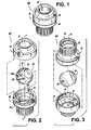
- Valve 100 includes, inter alia, a valve housing 10 having an upper body portion 20 and a lower body portion 30 and a generally spherical valve member 50.
- the upper and lower body portions 20/30 of the housing 10 define an internal chamber 16 for accommodating the valve member 50 and a central axis "X" for the valve.
- the housing 10 also has axially aligned inlet and outlet ports, 12 and 14 respectively, formed in the upper and lower body portions, 20 and 30 respectively.
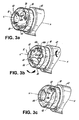
- FIG. 3a illustrates valve assembly 100 in the open position; wherein the axial bore 52 of the valve member 50 is axially aligned with the inlet port 12 and outlet port 14 of the valve housing 10.
- FIG. 3c illustrates the valve assembly 100 in the closed position; wherein the axial bore 52 of the valve member 50 is out of alignment with the inlet and outlet ports 12/16 of the valve housing 10.
- FIG. 3b provides a detail of the valve assembly 100 in an intermediate position. It should be noted that in FIGS. 3a through 3c , valve assembly 100 is shown mounted on the neck of a container 62.
- valve member 100 moves between the open position and the closed position when the upper body portion 20 of the housing is rotated about the central axis "X" between about 57 degrees and about 77 degrees with respect to the lower body portion 30.
- the valve member 100 is mounted for axial rotation within the interior chamber about an axis "Y" (see FIG. 3b ) extending perpendicular to the central axis "X" defined by the upper and lower body portions 20/30 of the valve housing 10.
- the valve member 50 includes a sealing surface 54 which is adapted for sealing engagement with annular valve seat 18 formed in the housing 10 when the valve is in the closed position.
- the sealing surface 54 of the valve member 50 includes an annular recess 56 (see FIG. 2 ) having an o-ring (not shown) disposed therein.
- Diametrically opposed pivot pins 58 extend radially outwardly from the surface of valve member 50 for accommodation within diametrically opposed recesses 32a and 32 formed in the lower body portion 30 of the housing 10 to facilitate the axial rotation of valve member 50.
- a camming mechanism is operatively associated with the valve housing 10 and the valve member 50 for moving the valve member 50 between the open position of FIG. 3a and the closed position of FIG. 3c .
- the camming mechanism includes cam lobes 60a, 60b formed on the exterior surface of the valve member 50 and a cam pin 22 which extends radially inwardly from the interior surface of the upper body portion 20 of the housing 10 to cooperate with the cam lobes.
- the valve assembly can be equipped with a drive ring which is engaged over the upper body portion of the housing.
- the cam pin can be associated with the drive ring such that the drive ring actuates the valve member.
- the cam lobes 60a, 60b are orientated with respect to the axis of rotatation "Y" of the valve member 50 at angles to one another.
- Each cam lobe 60a, 60b has a leadig edge 61a, 61b that interacts with the cam pin 22. This interaction facilitates movement of the valve member 50 when the upper body portion 20 is rotated about the longitudinal axis X of the valve assembly 100.
- the valve member 50 is moved between the open and closed positions, it is rotated about the pivot axis "Y" which extends through the pivot pin 58 of valve member 50, as illustrated in FIG. 3b .
- cam lobes 60a and 60b a single arcuate recess or pair of recesses can be formed in the exterior surface of valve member 50.
- the length of cam pin 22 would be selected so that it extends into the camming recess(es) and actuates the valve member 50 between the open and closed positions upon the relative axial rotation of the two body portions 20/30 of the housing 10 with respect to each other.
- the lower body portion 30 of valve assembly 100 has a female thread series 34 formed thereon for engaging with corresponding male series associated with a receptacle (e.g. bottle, container, etc.), tubing or the like.
- Ribbed surface 36 is provided on the exterior of the lower body portion 30 of the housing 10 to facilitate the rotational engagement of the threads.
- a water pressure test was conducted on a valve assembly similar to that described above.
- the entire valve was manufactured from a rigid theremoplastic and did not include O-ring seals.
- the camming lobes were constructed such that 67 degrees of rotation was required to move the valve between the open and the closed position.
- the axial bore of the valve was approximately 3/4" in diameter.
- Six feet of water was applied to the valve through a 3/8" tube that was secured to the valve outlet. No leaking of the valve was observed and therefore, it was concluded that this embodiment of the valve assembly was capable of sealing fluid at a pressure of 3 psi (minimum).
- valve 200 is similar in structure and operation to valve assembly 100. However, unlike valve assembly 100, valve assembly 200 includes a frangible ring 270 which is adapted to be engaged with the housing (i.e., the upper and lower body portions 220, 230) of the valve assembly 200. The frangible ring 270 has been added to valve assembly 200 to provide a visual indication of whether the valve has been previously opened. Frangible ring 270 is molded around the upper and lower body portions 220, 230 of the housing so that when the body portions are rotated relative to each of the, the ring 270 is broken. Such a tamper-proof feature would be useful in applications where the valve is with consumer beverages, for example.
- valve 300 is similar in structure and operation to valve assembly 100. However, unlike valve 100, valve 300 includes a frangible sealing disc 370 which is positioned within the interior chamber 316 defined in part by the lower body portion of the housing. Frangible sealing disc 370 can function as a tamper-proof feature, as well as, provide an additional seal for valve assembly 300.
- the valve member 350 has a shape protuberance 364 formed on its exterior surface. When the valve member 350 is rotated from the open to the closed position the protuberance 364 punctures the sealing disc 370 allowing fluid or air to flow through the valve member 350 when it is returned to the closed position.
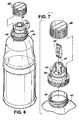
- valve assembly 400 is similar in structure and operation to valve assembly 100. As shown in these figures, valve assembly 400 is threadably engaged with the neck 462 of container 465. A cap 488 is provided which engages with the upper portion 420 of the valve assembly 400. Like the previously disclosed valve assemblies, valve member 450 has a axial bore 452 formed therein which allows fluid or air to flow through the valve assembly 400 when the valve member 450 is in the open position. Still further, the axial bore 452 is adapted for receiving and storing an article of manufacture 453 or fluid, such as for example, a prize, a ticket, a vitamin supplement, or a medication. In such embodiments, it would be advantageous to insert a sealing disc into the valve assembly similar that disclosed with reference to FIG. 5 to prevent to article of manufacture from falling into the container during storage. Alternatively, a removable seal can be placed over the mouth of container 462.
- valve 400 is mounted on the end of a tubing assembly 472.
- Tubing assembly 472 includes two end connectors 474a, 474b and an elongated tube 476.
- End connector 474a is threadably engaged with the neck of container 465 and includes a central aperture which is adapted to allow tube 476 to telescope in and out of container 465.
- Valve assembly 400 is engaged with end connector 474b such that when the valve is in the open position, fluid can flow from the container 465 through the tubing assembly 472 and out of the valve 400.
- FIG. 9 illustrates valve assembly 400 mounted on the neck 462 of container 465.
- Valve assembly 400 is shown in the open position having straw assembly 572 inserted into the axial bore 552.
- Straw assembly 572 includes a straw 576 and a plug member 574.
- the plug member 574 has a circumferential O-ring 575 and is adapted for sealing engagement with the inlet port of valve 400.
- valve assembly 500 is being used to meter the flow between two containers 565a, 565b.
- the flow path between the containers includes upper and lower conduit assemblies 572a, 572b and valve assembly 500.
- the conduit assemblies are sealingly engaged between containers 565a, 565b and the valve assembly 500.
- Valve assembly 500 is similar in structure and function to valve assembly 100. However, unlike valve assembly 100, valve assembly 500 includes actuator arms 528a through 528d that facilitate the relative rotation of the upper body portion 520 of the valve assembly 500 with respect to the lower body portion 530 thereby moving the valve member between the open and closed positions. O-rings 525 are provided to seal the connections of the components and prevent leakage from the flow path.
- Colostomy bag assembly 665 includes a bag 667, a proximal ring 669 and a distal ring 671.
- the proximal ring 669 has an outer flange that is sealingly engaged with the bag 667.
- Two retaining pins 675a, 675b are formed on the inside diameter of the proximal ring 669. These pins 675a, 675b are inserted into corresponding engagement recesses 629a, 629b formed in valve assembly 600 and secure the valve assembly 600 to the proximal ring 669.
- distal ring 671 which is secured to the surface of the patient's body, includes retaining pins 673a, 673b that are inserted into corresponding engagement recesses 631 a (not show), 631b formed in valve assembly 600.
- Valve assembly 600 has been equipped with an actuator arm 628 which allows the patient to move the valve between the open and the closed position as desired.
- valve assembly 700 which includes a valve assembly constructed in accordance with an alternative embodiment of the present invention and designated by reference numeral 700.
- valve assembly 700 is similar in structure and operation to the previously disclosed valves, but unlike the prior valves, valve assembly 700 has a plurality of flow passages 753 formed in the valve member 750.
- the flow passages 753 extend along an axis that is perpendicular to the axial bore 752 such that when the valve member is in the closed position, fluid traverses the valve through the plurality of flow passages 753. Hence when the valve assembly 700 is in the open position, a single jet of water is emitted from the showerhead assembly and when it is in the closed position, water streams from the flow passages 753.
- O-ring seals 755a, 755b and 757a, 757b are provided at both ends of the axial bore 752 and flow passages 753 to properly seal the valve when in the open and closed positions, respectively.
- the showerhead disclosed in FIG. 13 is also equipped with a control ring 790 that sealingly engages with the upper portion 720 of the valve assembly 700 using O-ring seal 792.
- Control ring 790 has a drive pin 722 formed on its interior surface. Drive pin 722 projects through the slot 721 formed in the upper portion 720 of the valve assembly 700 and engages with the cam lobes 760a, 760b formed the valve member 750.
- rotation of the control ring 790 with respect to the lower body portion 730 of the valve assembly 700 moves the valve member between the open and the closed positions.
- showerhead assembly described hereinabove can be adapted for use for metering an air supply rather than fluid.
- valve assembly 800 which illustrates a valve assembly (designated by reference numeral 800) constructed in accordance with the present invention positioned within the inlet 862 of fuel tank.
- valve assembly 800 allows for the elimination of a removable gas cap and only requires an approximately 67 degrees rotation of drive ring 890 to open the valve.
- the axial bore 852 of the valve member would be adapted for receiving a standard fuel pump nozzle 855.
- FIGS. 15 and 16 there is illustrated a surgical instrument constructed in accordance with a preferred embodiment of the subject invention and designated generally by reference numeral 900.
- Minimally invasive surgical procedures are commonly performed by passing surgical instruments through a narrow tube or cannula inserted through a small entrance incision formed in a patient's body using a trocar or obturator.
- laparoscopic surgical procedures are performed within the abdominal cavity through small incisions formed in the abdominal wall.
- insufflating gases are introduced into the abdominal cavity to raise the abdominal wall or peritoneum away from the vital organs within the abdominal cavity, thereby providing an adequate region in which to operate.
- surgical instrument 900 has been equipped with the valve assembly of the present invention to prevent the egress of insufflating gases through the cannula in the absence of a surgical instrument.
- Surgical instrument 900 is intended for use as an access device, and more particularly, as a device to facilitate the introduction of a surgical instrument into a person's body during a minimally invasive surgical procedure.
- Surgical instruments introduced into a patient's body through the surgical instrument 900 of the subject invention can include. for example, clip appliers, graspers, dissectors, retractors, staplers, laser fibers, photographic devices, endoscopes, laparoscopes, tubes; and the like.
- Surgical instrument or access device 900 includes a proximal valve housing 910 having an inlet port 912 for receiving surgical instruments.
- Valve housing 910 includes an upper body portion 920 and a lower body portion 930 which define, among other things, a generally hemispherical internal chamber 916 for accommodating a generally spherical valve member 950.
- Internal chamber 916 communicates with an outlet port 914 of the valve housing 910 which is axially aligned with the inlet port 912.
- Valve housing 910 is operatively associated with a lower cannula housing 980.
- the valve housing 910 and cannula housing 980 are formed of a polycarbonate material.
- An elongated cannula sleeve 982 extends distally from the cannula housing 980.
- Cannula sleeve 982 has an elongated passageway 984 extending therethrough, which defines a longitudinal axis defined by reference character "X". Passageway 984 is axially aligned with the inlet port 912 and outlet port 914 of valve housing 910.
- Cannula sleeve 982 may be formed of stainless steel or another suitable rigid material such as polycarbonate materials or the like.
- An inlet conduit 986 is incorporated into cannula housing 980 to permit the passage of insufflation gases through the cannula sleeve 982 and into the patient's body cavity.
- the inlet conduit 986 can include a stopcock valve, which is not shown.
- Valve member 950 which is preferably formed from a polycarbonate material, is mounted for axial rotation within the interior chamber 916 about an axis extending perpendicular to the longitudinal axis of the cannula sleeve 982.
- Diametrically opposed pivot pins 958 extend radially outwardly from the surface of valve member 950 for accommodation within diametrically opposed recesses 932a, 932b to facilitate the axial rotation of valve member 950.
- An axial bore 952 extends through the valve member 950, and a convex sealing surface 954 is provided on valve member 950, spaced from axial bore 952.
- Valve member 950 is mounted for movement between an open position and a closed position.
- the axial bore 952 is axially aligned with the elongated passageway 984 of cannula sleeve 982 and the inlet and outlet ports 912, 914 of valve housing 910.
- the axial bore 952 extends perpendicular to the elongated passageway 984 of cannula sleeve 982 and the sealing surface 954 is axially aligned with the inlet port 912 of valve housing 910.
- a camming mechanism is operatively associated with the valve housing 910 and the valve member 950 for moving the valve member 950 between the open position of FIG. 17a and the closed position of FIG. 17c .
- the camming mechanism includes arcuate cam lobes 960a, 960b formed on the exterior surface of the valve member 950 and a cam pin 922 which extends radially inwardly from the interior surface of the upper housing portion/drive ring 920 to cooperate with the cam lobes. As before, a leading edge of the cam lobes 960a, 960b interacts with the cam pin 922.
- valve member 950 This interaction facilitates movement of the valve member 950 when the drive ring 920 is rotated about the longitudinal axis "X" of cannula sleeve 982.
- valve member 950 When the valve member 950 is moved between the open and closed positions, it is rotated about the pivot axis "Y" which extends through the pivot pin 958 of valve member 950, as illustrated in FIG. 3b .
- Drive ring 920 is rotatably mounted on the proximal end of valve housing 910 and includes diametrically opposed radially inwardly extending guide ribs 924 which cooperate with an annular guide surface 938 formed on the exterior of the lower body portion 930 of the valve housing 910. Stop surfaces 940 limit the rotational motion of upper body portion/drive ring 920 relative to the longitudinal axis of the cannula sleeve 982.
- a fluted manipulation knob 990 is cooperatively engaged with the drive ring 920.
- Manipulation knob 990 includes inlet port 992, which is aligned with the axial passageway 984 of cannula sleeve 982 and defines in part the inlet port 912 of valve housing 910.
- the engagement of drive ring 920 and manipulation knob 990 is accomplished through the coupling of a pair of diametrically opposed radially outwardly extending engagement tabs 926 on drive ring 920 (only one tab is shown in FIG. 16 ) with a pair of corresponding diametrically opposed interior recess 994a, 994b formed in the interior cavity of manipulation knob 990.
- Alternative structural means may be provided to enable ready manipulation of drive ring 920.
- Valve housing 910 further includes a membrane seal 996 located proximal to the interior chamber 916 and retained within an annular recess.
- Membrane seal 996 has a central slitted opening 998 that is axially aligned with the outlet port 912 of valve housing 910 and the passageway 984 of the cannula sleeve 982.
- Central opening 998 is dimensioned and configured to accommodate the passage of a surgical instrument therethrough. The membrane seal 996 will help to prevent the egress of insufflation gasses from the access device 900 when an instrument is present therein and the valve member 950 is in an open position.
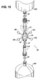
- FIGS. 18 and 19 there is a perspective view of another embodiment of the surgical access device of the subject invention, which is designated by reference numeral 1000 and includes a detachable valve housing 1010. More particularly, as best seen in FIG. 5 .
- the valve housing 1010 is detachably connected to the cannula housing 1080. This will enable a surgeon to utilize the cannula housing 1080 during the performance of procedures in which the valve housing is not required. It will also enable the surgeon to readily remove specimens from the surgical site.
- the detachable relationship of valve housing 1010 and cannula housing 1080 is facilitated by a threaded connection therebetween.
- Alternative coupling arrangements are envisioned and well within the scope of the subject disclosure.
- valve assembly of the subject invention can be used in alternative applications not described hereinabove.
- the valve can be installed in a sink drain to eliminate the need for a plug.
- the valve can replace bungs or plugs used to seal penetrations in the hull of boats.
- the valve can replace caps on hand creams, toothpaste, etc.
- the surgical access device of the present disclosure may, according to various embodiments, provide for a valve member having more than one lumen/bores extending therethrough, e.g., FIG. 13 (as used herein, the terms “lumen” and “bore” are intended to be synonymous).
- a further example of such an arrangement is set forth below. While the example embodiment discussed hereinbelow relates to a valve member for a surgical device that provides a substantial seal between a body cavity of a patient and the outside atmosphere before, during and after insertion and manipulation of an instrument through the seal, the embodiment shown and its description in the surgical context is merely illustrative. It should be recognized that the principles described hereinbelow and illustrated in FIGs. 20-22c are equally applicable in any of the other types of valves described in this application, e.g., consumer beverage, pharmaceutical containers, automobile, etc.
- a surgical access device of the present disclosure contemplates the introduction and manipulation of various types of instrumentation adapted for insertion through a trocar and/or cannula assembly while maintaining a substantially fluid-tight interface about the instrument to preserve the atmospheric integrity of a surgical procedure from leakage.
- instrumentation include, but are not limited to, clip appliers, graspers, dissectors, retractors, staplers, laser probes, photographic devices, endoscopes and laparoscopes, tubes, and the like.
- these instruments can be designed with a variety of tip configurations and a variety of diameters. Such instruments will collectively be referred to as "instruments” or “instrumentation” or "surgical objects.”
- proximal refers to the end of the device that is closer to the user and the term “distal” refers to the end of the device that is farther from the user.
- distal refers to the end of the device that is farther from the user.
- FIG. 20 illustrates a surgical access device designated generally by reference numeral 2100.
- the surgical access device 2100 includes a portal 2110 having a proximal end 21 10a and a distal end 2110b, the distal end 2110a being dimensioned for insertion within tissue to access an underlying tissue site.
- the portal 2110 defines a longitudinal axis "X" and has a longitudinal opening 2112 disposed at the proximal end 21 10a for reception of a surgical object "I.”
- the portal 2110 includes a cannula housing 2114 disposed at the proximal end 2110a and an elongated cannula 2116 disposed at the distal end 2110b and extending distally from the cannula housing 2114.
- the cannula housing 2114 includes an upper body portion 2114a and a lower body portion 2114b which define, among other things, a generally hemispherical internal chamber 2115 ( FIGS. 22a-22c ) for accommodating a generally spherical valve 2120 in mechanical cooperation.
- the internal chamber 2115 communicates with an outlet 2117 of the cannula housing 2114 which is axially aligned with the longitudinal opening 2112 and the cannula 2116.
- the cannula housing 2114 may be formed of a polycarbonate material.
- the cannula 2116 has an elongated passageway 2118 extending therethrough.
- the passageway 2118 is axially aligned with the longitudinal opening 2112 and outlet 2117 of the cannula housing 2114.
- the cannula 2116 may be formed of stainless steel or another suitable rigid material such as polycarbonate materials or the like.
- An inlet conduit 2119 may be incorporated into the cannula housing 2114 to permit the passage of insufflation gases through the cannula 2116 and into the patient's body cavity.
- the valve 2120 which is preferably formed from a polycarbonate material, defines first and second lumens 2130, 2140 therethrough and is mounted for axial rotation within the internal chamber 2115 about a transverse axis "Y" ( FIG. 22B ).
- Transverse axis "Y” extends perpendicular to the longitudinal axis "X” of the portal 2110.
- Each lumen 2130, 2140 includes one or more seals 2132, 2142 disposed therein.
- Each seal 2132, 2142 defines a passage 2134, 2144 for reception of the surgical object "I" in substantial sealed relation therewith.
- the valve 2120 is selectively positionable between a first orientation ( FIG. 22a ) and a second orientation ( FIG.
- Each lumen 2130, 2140 may be disposed in substantial alignment with the longitudinal opening 2112 and/or the longitudinal axis "X" of the portal 2110. More particularly, each lumen 2130, 2140 defines a respective longitudinal axis "L1", “L2” wherein each longitudinal axis "L1", “L2” of each lumen 2130, 2140 may be separately configured to be selectively positioned in substantial alignment with the longitudinal axis "X" of the portal 2110 whereby the longitudinal axis "L1", “L2” of the respective lumen 2130, 2140 and the longitudinal axis "X" of the portal 2110 define the passage for reception of the surgical object "I.”
- the longitudinal axis "L1" of the first lumen 2130 may be disposed in substantial alignment with the longitudinal axis "X" of the portal 2110 in the first orientation ( FIG.
- the longitudinal axis "L2" of the second lumen 2140 may be disposed in substantial alignment with the longitudinal axis "X" of portal 2110 in the second orientation ( FIG. 22c ).
- the first lumen 2130 may be disposed substantially orthogonal to the second lumen 2140, although any suitable offset angle between these lumen may be employed.
- the valve 2120 in addition to the valve 2120 being selectively positionable between a first orientation ( FIG. 22a ) and a second orientation ( FIG. 22c ), the valve 2120 may also be positionable in a third orientation, such as a transition orientation that is located between the first and second orientations, as shown in FIG.
- the third orientation may be a "closed" position, such that the inlet and outlet ports of the housing are sealed.
- the third orientation may be a position in which the inlet and outlet ports of the housing are aligned with a third lumen (not shown) of the valve member.
- a third lumen not shown
- any number of lumens through the valve member are possible, the lumens having a variety of diameters, e.g., different or possibly the same, may have seals or no seals.
- the first lumen 2130 includes a first seal 2132 and the second lumen 2140 includes a second seal 2142.
- the first seal 2132 has a first diameter and the second seal 2142 has a second diameter that may be different from the first diameter of the first seal 2132 for receiving different sized instruments in substantial sealing relationship.
- Each seal 2132, 2142 may also have the same diameter.
- the seal diameters typically range in size from about 1mm to about 15mm. In particular embodiments, one of the two seals may have diameters of 2mm, 3mm, or 5mm and the other seal may have diameters of 10mm, 12mm, or 15mm.
- valve 2120 includes diametrically opposed pivot pins 2122, 2124 (2124 not shown) that extend radially outwardly from the surface of valve 2120 for accommodation within diametrically opposed recesses 2126, 2128 within the cannula housing 2114 to facilitate the rotation of valve 2120 about longitudinal axis "Y.”
- the valve 2120 includes a camming assembly 2150 for selectively positioning the valve 2120 between the first and second orientation about a transverse axis "Y" ( FIG. 22b ).
- the camming assembly 2150 includes a cam surface 2152 formed on an exterior surface of the valve 2120 and a cam pin 2155 formed on a drive ring 2160 located within an interior surface of the upper body portion 2114a of the portal 2110 for engaging the cam surface 2152.
- the cam surface 2152 is defined by a pair of cam lobes 2154, 2156 disposed at an angle relative to each other.
- the cam pin 2155 extends radially inwardly from the drive ring 2160 mounted on the portal 2110 to cooperate with the cam lobes 2154, 2156.
- the drive ring 2160 is rotatable about the longitudinal axis "X" of the portal 2110, wherein rotation of the drive ring 2160 causes the valve 2120 to rotate between the first and second orientations about the transverse axis "Y.”
- a fluted manipulation knob 2170 is operatively coupled to the drive ring 2160 for selectively positioning the valve 2120 between the first and second orientations.
- leading edges 2154E, 2156E of the cam lobes 2154, 2156 interact with the cam pin 2155. This interaction facilitates movement of the valve 2120 when the drive ring 2160 is rotated about the longitudinal axis "X.”
- the valve 2120 pivots about the transverse axis "Y", which extends through pivot pins 2122, 2124 of valve member 2120, as illustrated in FIG. 22b .
- the drive ring 2160 is rotatably mounted on the upper body portion 2114a of cannula housing 2114 and includes diametrically opposed radially inwardly extending guide ribs 2162a, 2162b which cooperate with an annular guide surface 2164 formed on the exterior of the lower body portion 2114b of the cannula housing 2114. Stop surfaces 2166a, 2166b (2166b not shown) limit the rotational motion of upper body portion 2114a and drive ring 2160 relative to the longitudinal axis "X.”
- the manipulation knob 2170 is cooperatively engaged with the drive ring 2160.
- the manipulation knob 2170 is disposed in axial alignment with longitudinal axis "X.”
- the engagement of drive ring 2160 and manipulation knob 2170 is accomplished through the coupling of a pair of diametrically opposed radially outwardly extending engagement tabs 2168a, 2168b (2168b not shown) on drive ring 2160 with a pair of corresponding diametrically opposed interior recess 2172a, 2172b formed in the interior cavity of the manipulation knob 2170.
- Alternative structures may be provided to enable ready manipulation of drive ring 2160.
- a flange 2180 projects radially outwardly from the lower body portion 2114b of cannula housing 2144 to provide leverage to the surgeon when the manipulation knob 2170 is rotated.
- valve 2120 may be field replaceable.
- the surgical access device 2100 is provided with a valve 2120 having a 5mm lumen and a 10mm lumen, the physician would be able to substitute a valve 2120 having a 10mm lumen and a 12mm lumen.
- Other combinations of lumen sizes are contemplated and may be provided as part of a surgical kit.
- the lumens 2130, 2140 may be devoid of seals, in which case one or more instrument (e.g., septum) and/or zero-closure (e.g., duckbill, flapper) seals may be provided elsewhere in the housing.
- instrument e.g., septum
- zero-closure e.g., duckbill, flapper
- the provision of different sized lumens 2130, 2140 may still provide sealing advantages as compared to conventional valve arrangements, e.g., by preventing instruments having varying diameters from being over-angulated by a user.
- the relatively small instrument when a relatively small instrument is placed into a relatively large lumen, the relatively small instrument may be over-angulated relative to the wall of the lumen, thereby increasing the likelihood that the instrument will cause an instrument and/or zero-closure seal located elsewhere in the housing to experience "cat-eyeing" (e.g., "cat-eyeing” refers to a loss of sealing pressure due to small spaces that can form between a seal and the outer diameter of an instrument).
- a user may select a lumen that is dimensionally appropriate for the instrument to be used, thereby reducing the likelihood that the instrument will be over-angulated relative to the walls of the lumen and reducing the likelihood that the instrument will cause an instrument and/or zero-closure seal located elsewhere in the housing to experience "cat-eyeing.”
- a benefit e.g., the reduction of a likelihood of over-angulating and "cat-eyeing," may also be provided by embodiments of the present invention in which the seals 2132, 2142 are disposed within the lumen 2130, 2140.
Abstract
Description
- This application is a continuation-in-part of currently-pending
U.S. Patent Application Serial No. 11/640,009, filed December 15, 2006 U.S. Patent Application Serial No. 10/856,011, filed May 28, 2004 issued as U.S. Patent No. 7,165,568 on January 23, 2007 , which is based onU.S. Provisional Patent Application Serial No. 60/516,569, filed Oct. 31, 2003 526,158, filed May 29, 2003 - The subject invention relates generally to the field of sealing mechanisms, and more particularly to, a compact valve assembly for use in a variety of applications, which includes a multi-lumen/bore, generally spherical valve member that is readily actuated between positions, e.g., open and closed positions, by a camming mechanism.
- Ball valves are well known to those skilled in the art and are commonly used in a variety of applications and industries. Typically, in applications that concern controlling the flow of a fluid, an apertured ball valve is selected. In an apertured ball valve, a generally spherical valve member that has a flow aperture or passage formed therethrough is positioned for rotational movement within a valve housing. The valve operation or function is broken down into two separate stages. First, the ball moves between an open and a closed position by rotating through 90 degrees, such that the aperture or flow passage moves from an orientation coaxial with the flow direction, i.e. when the valve is open, to a position whereby the ball aperture is normal or perpendicular to the flow direction. Second, the valve seals in the closed position to prevent flow through the aperture across the ball valve. Therefore, the on-off control of flow through the valve is achieved by rotating the ball through 90 degrees within the valve housing.
- In prior art ball valves; the rotation of the ball (i.e., valve member) is typically effectuated by an actuator mechanism that protrudes from the valve housing and is configured to rotate about an axis perpendicular to that of the valve flow. Such a valve is disclosed in
U.S. Pat. No. 6,695,285 to Hotton et al. - Several disadvantages are associated with this type of ball valve. For example, the extension of an actuator from the sidewall of the valve is cumbersome and not desirable for applications where space limitations and physical access to the actuator are a concern. Still further, the actuator in these valves must be rotated or turned through at least 90 degrees in order for the valve to move between the fully open and fully closed positions.
- Therefore, it would be beneficial therefore, to provide a valve/seal mechanism that is compact, reliable and readily actuated between the open and closed position and actuated with a minimal amount of rotational movement.
- The subject application is directed to a valve/seal assembly that is adapted for use in a variety of applications, such as for example, medical, consumer beverage, pharmaceutical containers, automobile, household appliance and marine. The disclosed valve includes, inter alia, a valve housing having an upper body portion and a lower body portion and a generally spherical valve member. The upper and lower body portions of the housing define an internal chamber for accommodating the valve member and a central axis for the valve. The housing also has axially aligned inlet and outlet ports formed in the upper and lower body portions, respectively.
- The generally spherical valve member is seated within the internal chamber of the valve housing and has an axial bore extending therethrough. The valve member is mounted for movement between an open position; wherein the axial bore of the valve member is axially aligned with the inlet and outlet ports of the valve housing, and a closed position; wherein the axial bore of the valve member is out of alignment with the inlet and outlet ports of the valve housing. Preferably, the valve member moves between the open position and the closed position when the upper body portion of the housing is rotated about the central axis between about 57 degrees and about 77 degrees with respect to the lower body portion. It is presently envisioned that the valve member is mounted for axial rotation within the interior chamber about an axis extending perpendicular to the central axis defined by the upper and lower body portion of the valve housing.
- Preferably, the valve member includes a sealing surface adapted for sealing engagement with a valve seat formed in the housing when the valve is in the closed position. In applications where a pressure is applied to the fluid or air metered by the valve, the sealing surface of the valve member is adapted to include an annular recess having an o-ring disposed therein.
- The valve assembly further includes a mechanism that is operatively associated with the valve housing and the valve member for moving the valve member between the open position and the closed position when the upper body portion of the housing is rotated about the central axis with respect to the lower body portion. In a preferred embodiment, the mechanism for actuating the valve assembly is a camming mechanism.
- In a present embodiment, the camming mechanism includes cam surfaces formed on the exterior surface of the valve member and a cam pin formed on the interior surface of the upper body portion of the housing. It is envisioned that the cam surfaces formed on the exterior surface of the valve member are defined by a pair of cam lobes formed at angles to one another. The cam lobes can be arcuate or linear in configuration.
- In a further embodiment of the present invention, the camming mechanism includes at least one arcuate recess formed on the exterior surface of the valve member and a cam pin formed on the interior surface of the upper body portion of the housing for engaging with the cam recess.
- In a preferred embodiment, the housing for the valve assembly includes means associated with the inlet port for engaging the valve with a receptacle or tubing. Additionally, if desired, the housing can includes means associated with the outlet port for engaging the valve with a receptacle or tubing.
- In applications that require the valve to include a tamper-proof feature to ensure the purity of the substance contained within the bore of the valve member or in the receptacle or container, upon which the valve is affixed to, the valve further includes a frangible ring engaged with exterior of the valve housing to provide a visual indication of whether the valve has been opened. Alternatively or in combination, the valve can include a frangible sealing disc inserted into the interior chamber of the valve to again provide a visual indication of whether the valve has been opened. This sealing disc also functions as a secondary seal for the valve until its initial use. In this embodiment, it is envisioned that the valve member includes a mechanism for puncturing the disc when the valve is opened. For example, a sharp protuberance can be formed on the bottom of the valve member which cuts the sealing disc when the valve is moved from the closed to the open position.
- In an alternative embodiment, the axial bore of the valve member is adapted and configured for receiving and storing an article of manufacture when the valve is in the closed position. For example, an award or small prize may be stored in the bore and revealed when the valve is opened. Still further, the valve could be mounted to a water bottle and the bore of the valve could contain a vitamin or supplement which is dropped into the water when the valve is opened.
- It is further envisioned that the valve can include a mechanism associated with the valve housing for facilitating the axial rotation of the upper body portion of the housing relative to the lower body portion.
- In an alternative embodiment, a plurality of flow passages are formed in the valve member and extend therethrough along an axis that is perpendicular to the axial bore such that when the valve is in the closed position, fluid or air traverses the valve through the plurality of flow passages.
- The present disclosure is also directed to a surgical access device which includes, among other things, a valve housing, an elongated cannula sleeve operatively associated with the housing, a generally spherical valve member disposed within an interior chamber defined in the housing and a mechanism operatively associated with the valve housing and the valve member for moving the valve member between the open position and the closed position.
- The valve housing defines an interior chamber and a valve seat for accommodating the valve member. Axially aligned inlet and outlet ports are formed in the housing and extend from the valve exterior to the interior chamber.
- The elongated cannula sleeve that is operatively associated with the valve housing, has an elongated passageway extending therethrough that defines a longitudinal axis aligned with the inlet and outlet ports of the valve housing. In a disclosed embodiment, the cannula sleeve depends from a cannula housing associated with the valve housing. It is envisioned that the cannula housing can be detachably connected to the valve housing.
- The generally spherical valve member is seated within the valve housing and has an axial bore extending therethrough. The valve member is mounted for movement between an open position and a closed position. In the open position, the axial bore of the valve member is axially aligned with the elongated passageway of the cannula sleeve and the inlet and outlet ports of the valve housing. In the closed position, the axial bore of the valve member extends perpendicular to the elongated passageway of the cannula sleeve and the inlet and outlet ports of the valve housing. It is envisioned that the valve member is mounted for axial rotation within the valve interior chamber about an axis extending perpendicular to the axially aligned inlet and outlet ports of the valve housing.
- It is presently envisioned that the valve member includes a convex sealing surface, which is aligned with the inlet port of the valve housing when the valve member is in the closed position. In alternative embodiments that require a pressure tight seal, the sealing surface of the valve member includes an annular recess having an o-ring disposed therein.
- In a preferred embodiment, the mechanism for moving the valve member includes cam surfaces formed on the exterior surface of the valve member and a cam pin mounted for movement relative to the cam surfaces of the valve member. Preferably, the cam pin extends radially inwardly from a drive ring supported on the valve housing and mounted for rotation about the longitudinal axis of the cannula sleeve. The rotation of the drive ring causes corresponding rotation of the valve member within the valve seat of the valve housing.
- In a disclosed embodiment of the surgical access device, the cam surfaces formed on the exterior surface of the valve member are defined by a pair of cam lobes oriented with respect to the axis of rotation of the valve member at angles to one another. In an alternative embodiment, the mechanism operatively associated with the valve housing and the valve member for moving the valve member between the open position and the closed position includes at least one arcuate recess formed on the exterior surface of the valve member and a cam pin formed on the interior surface of the housing for engaging with the cam recess.
- It is presently preferred that the surgical access device further includes a membrane seal located proximal to the valve seat, the membrane seal having an opening axially aligned with the elongated passageway of the cannula sleeve. The opening is dimensioned to accommodate the passage of a surgical instrument therethrough.
- Those skilled in the art would readily appreciate that the components of the disclosed valve assembly, or portions thereof, may be manufactured from any rigid, semi-rigid, hard or semi-hard material, such as plastic, rubber, metal or a composite. Still further, in medical applications the valve assembly can be made out of titanium or a similar biocompatible material.
- Additionally, the generally spherical valve member can be formed to have an interference fit with the valve seat so as to provide a tighter seal. By forming the valve member or valve seat slightly out-of-round, a tighter seal is created and more force is required to open the valve.
- It is also envisioned that a telescoping nozzle or sleeve can be disposed within the axial bore of the valve member and when the valve is moved to the open position, the nozzle or sleeve extends out of the valve inlet. This feature is useful in a variety of applications, such as for example, beverage or gasoline containers.
- Still further, it is envisioned that the valve assembly of the present invention can be connected to stepper motor and thereby be operated remotely.
- In accordance with various embodiments, the present invention may also provide for a valve assembly comprising: a) a valve housing having an upper body portion and a lower body portion, the upper and lower body portions defining an internal chamber for accommodating a valve member and a central axis for the valve, the housing having axially aligned inlet and outlet ports formed in the upper and lower body portions, respectively; b) a generally spherical valve member seated within the internal chamber of the valve housing and having first and second bores extending therethrough, the first bore defining a first longitudinal axis and the second bore having a second longitudinal axis offset relative to the first longitudinal axis, the valve member mounted for movement between a first position wherein the first bore of the valve member is axially aligned with the inlet and outlet ports of the valve housing and the second bore of the valve member is axially misaligned with the inlet and outlet ports of the valve housing, and a second position wherein the second bore of the valve member is axially aligned with the inlet and outlet ports of the valve housing and the first bore of the valve member is axially misaligned with the inlet and outlet ports of the valve housing; and c) a camming mechanism for moving the valve member between the first position and the second position, including cam surfaces formed on the exterior surface of the valve member and a cam pin formed on the interior surface of the upper body portion of the housing, wherein the cam surfaces formed on the exterior surface of the valve member are defined by a pair of arcuate cam lobes formed at angles to one another.
- The first bore may define a first diameter and the second bore may define a second diameter, the first diameter being different from the second diameter. Each one of the first and second bores may be configured and dimensioned to receive, when aligned with the inlet and outlet ports of the valve housing, a surgical instrument. There may be disposed in each one of the first and second bores respective first and second seals. The first seal disposed in the first bore may be configured and dimensioned to sealingly engage with a surgical instrument having a first instrument diameter and the seal of the second bore may be configured and dimensioned to sealingly engage with a surgical instrument having a second instrument diameter that is different from the first instrument diameter. The valve member may be mounted for movement to a third position wherein the first and second bores of the valve member are both axially misaligned with the inlet and outlet ports of the valve housing. The camming mechanism may include at least one arcuate recess formed on the exterior surface of the valve member and a cam pin formed on the interior surface of the upper body portion of the housing for engaging with the cam recess. The valve member may be mounted for rotation within the interior chamber about an axis extending perpendicular to the central axis defined by the upper and lower body portion of the valve housing. The housing may include a connection for a cannula tube. The valve assembly may also include a rotation mechanism for facilitating the axial rotation of the lower body portion of the housing relative to the upper body portion. The valve member may move between the first position and the second position when the upper body portion of the housing is rotated about the central axis between about 57 degrees and about 77 degrees with respect to the lower body portion.
- In accordance with various embodiments, the present invention may also provide for a surgical device comprising: a) a valve housing defining a valve seat for accommodating a valve member, and having axially aligned inlet and outlet ports; b) an elongated cannula sleeve operatively associated with the valve housing and having an elongated passageway extending therethrough which defines a longitudinal axis aligned with the inlet and outlet ports of the valve housing; c) a generally spherical valve member seated within the internal chamber of the valve housing and having first and second bores extending therethrough, the first bore defining a first longitudinal axis and the second bore having a second longitudinal axis offset relative to the first longitudinal axis, the valve member mounted for movement between a first position wherein the first bore of the valve member is axially aligned with the inlet and outlet ports of the valve housing and the second bore of the valve member is axially misaligned with the inlet and outlet ports of the valve housing, and a second position wherein the second bore of the valve member is axially aligned with the inlet and outlet ports of the valve housing and the first bore of the valve member is axially misaligned with the inlet and outlet ports of the valve housing; and d) a camming mechanism including cam surfaces formed on the exterior surface of the valve member and a cam pin mounted for movement relative to the cam surfaces of the valve member, wherein the cam pin extends radially inwardly from a drive ring supported on the valve housing and mounted for rotation about the longitudinal axis of the cannula sleeve, and wherein rotation of the drive ring causes corresponding rotation of the valve member within the valve seat of the valve housing, and wherein the cam surfaces formed on the exterior surface of the valve member are defined by a pair of cam lobes oriented with respect to the axis of rotation of the valve member at angles to one another.
- The first bore may define a first diameter and the second bore may define a second diameter, the first diameter being different from the second diameter. Each one of the first and second bores may be configured and dimensioned to receive, when aligned with the inlet and outlet ports of the valve housing, a surgical instrument. There may be disposed in each one of the first and second bores respective first and second seals. The first seal disposed in the first bore may be configured and dimensioned to sealingly engage with a surgical instrument having a first instrument diameter and the seal of the second bore may be configured and dimensioned to sealingly engage with a surgical instrument having a second instrument diameter that is different from the first instrument diameter. The valve member may be mounted for movement to a third position wherein the first and second bores of the valve member are both axially misaligned with the inlet and outlet ports of the valve housing. The camming mechanism may include at least one arcuate recess formed on the exterior surface of the valve member and a cam pin formed on the interior surface of the upper body portion of the housing for engaging with the cam recess. The valve member may be mounted for rotation within the interior chamber about an axis extending perpendicular to the central axis defined by the upper and lower body portion of the valve housing. The surgical device may also include a rotation mechanism for facilitating the axial rotation of the lower body portion of the housing relative to the upper body portion. The valve member may move between the first position and the second position when the upper body portion of the housing is rotated about the central axis between about 57 degrees and about 77 degrees with respect to the lower body portion.
- In accordance with various embodiments, the present invention may also provide for a valve assembly comprising: a) a valve housing defining a valve seat for accommodating a valve member, and having axially aligned inlet and outlet ports; b) a generally spherical valve member seated within the internal chamber of the valve housing and having first and second bores extending therethrough, the first bore defining a first longitudinal axis and the second bore having a second longitudinal axis offset relative to the first longitudinal axis, the valve member mounted for movement between a first position wherein the first bore of the valve member is axially aligned with the inlet and outlet ports of the valve housing and the second bore of the valve member is axially misaligned with the inlet and outlet ports of the valve housing, and a second position wherein the second bore of the valve member is axially aligned with the inlet and outlet ports of the valve housing and the first bore of the valve member is axially misaligned with the inlet and outlet ports of the valve housing, wherein the valve member is mounted for axial rotation within the valve seat about an axis extending perpendicular to the axially aligned inlet and outlet ports of the valve housing; and c) a camming mechanism operatively associated with the valve housing and the valve member for moving the valve member between the first position and the second position including cam surfaces formed on the exterior surface of the valve member and a cam pin mounted for movement relative to the cam surfaces of the valve member, wherein the cam surfaces formed on the exterior surface of the valve member are defined by a pair of cam lobes oriented with respect to the axis of rotation of the valve member at angles to one another.
- The first bore may define a first diameter and the second bore may define a second diameter, the first diameter being different from the second diameter. Each one of the first and second bores may be configured and dimensioned to receive, when aligned with the inlet and outlet ports of the valve housing, a surgical instrument. There may be disposed in each one of the first and second bores respective first and second seals. The first seal disposed in the first bore may be configured and dimensioned to sealingly engage with a surgical instrument having a first instrument diameter and the seal of the second bore may be configured and dimensioned to sealingly engage with a surgical instrument having a second instrument diameter that is different from the first instrument diameter. The valve member may be mounted for movement to a third position wherein the first and second bores of the valve member are both axially misaligned with the inlet and outlet ports of the valve housing. The camming mechanism may include at least one arcuate recess formed on the exterior surface of the valve member and a cam pin formed on the interior surface of the upper body portion of the housing for engaging with the cam recess. The valve member may be mounted for rotation within the interior chamber about an axis extending perpendicular to the central axis defined by the upper and lower body portion of the valve housing. The housing may include a connection for a cannula tube. The valve assembly may also include a rotation mechanism for facilitating the axial rotation of the lower body portion of the housing relative to the upper body portion. The valve member may move between the first position and the second position when the upper body portion of the housing is rotated about the central axis between about 57 degrees and about 77 degrees with respect to the lower body portion. The cam pin may extends radially inwardly from a drive ring supported on the valve housing and may be mounted for axial rotation relative to the axially aligned inlet and outlet ports, wherein rotation of the drive ring causes corresponding rotation of the valve member within the valve seat of the valve housing.
- So that those having ordinary skill in the art to which the present application appertains will more readily understand how to make and use the surgical access device and valve assembly of the present invention, embodiments thereof will be described in detail hereinbelow with reference to the drawings, wherein:
-
FIG. 1 is a perspective view of a valve assembly constructed in accordance with a preferred embodiment of the subject invention; -
FIG. 2 is an exploded perspective view from above of the valve assembly ofFIG. 1 with parts separated for ease of illustration; -
FIG. 3 is an exploded perspective view from below of the valve assembly ofFIG. 1 with parts separated for ease of illustration; -
FIG. 4 is an exploded perspective view of an alternative embodiment of the valve assembly of the present invention with parts separated for ease of illustration, wherein the valve includes a frangible ring; -
FIG. 5 is an exploded perspective view of an alternative embodiment of the valve assembly of the present invention with parts separated for ease of illustration, wherein the valve includes a sealing disc disposed within the interior chamber of the housing; -
FIG. 6 is a perspective view of a valve assembly constructed in accordance with an alternative embodiment of the subject invention, wherein the valve assembly is engaged with a beverage container and is adapted for engagement with a cap; -
FIG. 7 is a perspective view of a valve assembly constructed in accordance with an alternative embodiment of the subject invention with parts separated for ease of illustration, wherein a prize is stored within the bore formed in the valve member; -
FIG. 8 is a perspective view of a valve assembly constructed in accordance with a further alternative embodiment of the subject invention, wherein the valve assembly is mounted on the end of a tubing which is in fluid communication with a container; -
FIG. 9 is a perspective view of a valve assembly constructed in accordance with a further alternative embodiment of the subject invention, wherein the valve assembly is mounted on a container and a straw assembly is position within the open valve; -
FIG. 10 is a perspective view of the valve assembly of the present disclosure which illustrates the valve positioned between two containers; -
FIG. 11 is a perspective view of the valve assembly of the present disclosure adapted for use with a colostomy bag; -
FIG. 12 is a perspective view of the valve assembly ofFIG. 11 with parts separated for ease of illustration; -
FIG. 13 is an exploded perspective view of an alternative embodiment of the presently disclosed valve assembly with parts separated for ease of illustration, wherein the valve member includes a plurality of flow passages extending through the valve perpendicular to the central bore; -
FIG. 14 is a perspective view of an alternative application for the valve assembly of the present invention, wherein the valve is used in a automobile fuel tank; -
FIG. 15 is a perspective view of a surgical access device constructed in accordance with a preferred embodiment of the subject invention; -
FIG. 16 is an exploded perspective view of the surgical access device ofFIG. 15 with parts separated for ease of illustration; -
FIG. 17a is a perspective view in partial cross-section of the valve housing, which forms part of the surgical access device ofFIG. 15 , wherein the valve member is shown in an open position with the axial bore of the valve member aligned with the axially aligned inlet and outlet ports of the valve; -
FIG. 17b is a perspective view in partial cross-section of the valve housing of the subject invention, wherein the valve member is in transition from the open position ofFIG. 17a to the closed position ofFIG. 17c ; -
FIG. 17c is a perspective view in partial cross-section of the valve housing of the subject invention, wherein the valve member is disposed in a closed position so that the axial bore of the valve member is oriented perpendicular to the axially aligned inlet and outlet ports of the valve housing; -
FIG. 18 is a perspective view of another embodiment of the surgical access device of the subject invention, which includes a detachable valve housing; and -
FIG. 19 is a perspective view of the surgical access device ofFIG. 18 , with the valve housing separated from the cannula housing for ease of illustration. -
FIG. 20 is a perspective view of one embodiment of a surgical access device constructed in accordance with the present disclosure; -
FIG. 21 is a perspective view, with parts separated, of a cannula housing of the surgical access device ofFIG. 20 ; -
FIG. 22A is a perspective view in partial cross-section of the cannula housing, which forms part of the surgical access device ofFIGS. 20-21 , wherein a valve seated in the cannula housing is shown in a first orientation with a longitudinal axis of a first lumen of the valve aligned with a longitudinal axis of a portal of the surgical access device; -
FIG. 22B is a perspective view in partial cross-section of the cannula housing of the present disclosure, wherein the valve is disposed in transition from the first orientation ofFIG. 22A to a second orientation ofFIG. 22C ; and -
FIG. 22C is a perspective view in partial cross-section of the cannula housing of the present disclosure, wherein the valve is shown in a second orientation with a longitudinal axis of a second lumen of the valve aligned with the longitudinal axis of the portal of the surgical access device ofFIGS. 20-22B . - These and other features of the valve assembly and surgical access device of the present application will become more readily apparent to those having ordinary skill in the art form the following detailed description of the preferred embodiments.
- Referring now to the drawings wherein like reference numerals identify similar structural elements or features of the subject invention, there is illustrated in
FIG. 1 a valve assembly in accordance with the present invention and designated generally byreference number 100.Valve assembly 100 is adapted for use in a variety of applications, such as for example, medical, consumer beverage, pharmaceutical containers, automobile, household appliance and marine.Valve 100 includes, inter alia, avalve housing 10 having anupper body portion 20 and alower body portion 30 and a generallyspherical valve member 50. The upper andlower body portions 20/30 of thehousing 10 define aninternal chamber 16 for accommodating thevalve member 50 and a central axis "X" for the valve. Thehousing 10 also has axially aligned inlet and outlet ports, 12 and 14 respectively, formed in the upper and lower body portions, 20 and 30 respectively. - The generally
spherical valve member 50 is seated within theinternal chamber 16 of the valve housing and has anaxial bore 52 extending therethrough. Thevalve member 50 is mounted for movement within theinternal chamber 16 of thehousing 10 between an open position and a closed position.FIG. 3a illustratesvalve assembly 100 in the open position; wherein theaxial bore 52 of thevalve member 50 is axially aligned with theinlet port 12 and outlet port 14 of thevalve housing 10. In a like manner,FIG. 3c illustrates thevalve assembly 100 in the closed position; wherein theaxial bore 52 of thevalve member 50 is out of alignment with the inlet andoutlet ports 12/16 of thevalve housing 10.FIG. 3b , provides a detail of thevalve assembly 100 in an intermediate position. It should be noted that inFIGS. 3a through 3c ,valve assembly 100 is shown mounted on the neck of acontainer 62. - With continuing reference to
FIGS. 3a through 3c ,valve member 100 moves between the open position and the closed position when theupper body portion 20 of the housing is rotated about the central axis "X" between about 57 degrees and about 77 degrees with respect to thelower body portion 30. Thevalve member 100 is mounted for axial rotation within the interior chamber about an axis "Y" (seeFIG. 3b ) extending perpendicular to the central axis "X" defined by the upper andlower body portions 20/30 of thevalve housing 10. - The
valve member 50 includes a sealingsurface 54 which is adapted for sealing engagement withannular valve seat 18 formed in thehousing 10 when the valve is in the closed position. In applications where a pressure is applied to the fluid or air that is metered by the valve assembly, the sealingsurface 54 of thevalve member 50 includes an annular recess 56 (seeFIG. 2 ) having an o-ring (not shown) disposed therein. - Diametrically opposed pivot pins 58 (only one pin is shown in
FIG. 2 ) extend radially outwardly from the surface ofvalve member 50 for accommodation within diametricallyopposed recesses 32a and 32 formed in thelower body portion 30 of thehousing 10 to facilitate the axial rotation ofvalve member 50. - A camming mechanism is operatively associated with the
valve housing 10 and thevalve member 50 for moving thevalve member 50 between the open position ofFIG. 3a and the closed position ofFIG. 3c . The camming mechanism includescam lobes valve member 50 and acam pin 22 which extends radially inwardly from the interior surface of theupper body portion 20 of thehousing 10 to cooperate with the cam lobes. As will be described in detail herein below, the valve assembly can be equipped with a drive ring which is engaged over the upper body portion of the housing. In such an embodiment, the cam pin can be associated with the drive ring such that the drive ring actuates the valve member. - Referring again to
FIG. 3b , thecam lobes valve member 50 at angles to one another. Eachcam lobe leadig edge 61a, 61b that interacts with thecam pin 22. This interaction facilitates movement of thevalve member 50 when theupper body portion 20 is rotated about the longitudinal axis X of thevalve assembly 100. When thevalve member 50 is moved between the open and closed positions, it is rotated about the pivot axis "Y" which extends through thepivot pin 58 ofvalve member 50, as illustrated inFIG. 3b . - Those skilled in the art would readily appreciate that in lieu of the
cam lobes valve member 50. In this embodiment, the length ofcam pin 22 would be selected so that it extends into the camming recess(es) and actuates thevalve member 50 between the open and closed positions upon the relative axial rotation of the twobody portions 20/30 of thehousing 10 with respect to each other. - Referring again to
FIGS. 2 and 3 , thelower body portion 30 ofvalve assembly 100 has a female thread series 34 formed thereon for engaging with corresponding male series associated with a receptacle (e.g. bottle, container, etc.), tubing or the like. Ribbed surface 36 is provided on the exterior of thelower body portion 30 of thehousing 10 to facilitate the rotational engagement of the threads. - A water pressure test was conducted on a valve assembly similar to that described above. The entire valve was manufactured from a rigid theremoplastic and did not include O-ring seals. The camming lobes were constructed such that 67 degrees of rotation was required to move the valve between the open and the closed position. The axial bore of the valve was approximately 3/4" in diameter. Six feet of water was applied to the valve through a 3/8" tube that was secured to the valve outlet. No leaking of the valve was observed and therefore, it was concluded that this embodiment of the valve assembly was capable of sealing fluid at a pressure of 3 psi (minimum).
- Referring now to
FIG. 4 , there is illustrated an alternative embodiment of the valve assembly of the present invention designated generally byreference numeral 200.Valve 200 is similar in structure and operation tovalve assembly 100. However, unlikevalve assembly 100,valve assembly 200 includes afrangible ring 270 which is adapted to be engaged with the housing (i.e., the upper andlower body portions 220, 230) of thevalve assembly 200. Thefrangible ring 270 has been added tovalve assembly 200 to provide a visual indication of whether the valve has been previously opened.Frangible ring 270 is molded around the upper andlower body portions ring 270 is broken. Such a tamper-proof feature would be useful in applications where the valve is with consumer beverages, for example. - Referring now to
FIG. 5 which illustrates a further embodiment of the valve assembly of the present invention that has been designated byreference number 300.Valve 300 is similar in structure and operation tovalve assembly 100. However, unlikevalve 100,valve 300 includes afrangible sealing disc 370 which is positioned within theinterior chamber 316 defined in part by the lower body portion of the housing.Frangible sealing disc 370 can function as a tamper-proof feature, as well as, provide an additional seal forvalve assembly 300. In this embodiment, thevalve member 350 has a shape protuberance 364 formed on its exterior surface. When thevalve member 350 is rotated from the open to the closed position the protuberance 364 punctures thesealing disc 370 allowing fluid or air to flow through thevalve member 350 when it is returned to the closed position. - Referring now to
FIGS. 6 and 7 , which illustrate yet another embodiment of the valve assembly of the present invention designated generally byreference numeral 400.Valve assembly 400 is similar in structure and operation tovalve assembly 100. As shown in these figures,valve assembly 400 is threadably engaged with theneck 462 ofcontainer 465. Acap 488 is provided which engages with theupper portion 420 of thevalve assembly 400. Like the previously disclosed valve assemblies, valve member 450 has aaxial bore 452 formed therein which allows fluid or air to flow through thevalve assembly 400 when the valve member 450 is in the open position. Still further, theaxial bore 452 is adapted for receiving and storing an article ofmanufacture 453 or fluid, such as for example, a prize, a ticket, a vitamin supplement, or a medication. In such embodiments, it would be advantageous to insert a sealing disc into the valve assembly similar that disclosed with reference toFIG. 5 to prevent to article of manufacture from falling into the container during storage. Alternatively, a removable seal can be placed over the mouth ofcontainer 462. - Referring now to
FIGS. 8 and 9 which illustrate an alternate application forvalve 400. InFIG. 8 ,valve 400 is mounted on the end of atubing assembly 472.Tubing assembly 472 includes twoend connectors elongated tube 476.End connector 474a is threadably engaged with the neck ofcontainer 465 and includes a central aperture which is adapted to allowtube 476 to telescope in and out ofcontainer 465.Valve assembly 400 is engaged withend connector 474b such that when the valve is in the open position, fluid can flow from thecontainer 465 through thetubing assembly 472 and out of thevalve 400. -
FIG. 9 illustratesvalve assembly 400 mounted on theneck 462 ofcontainer 465.Valve assembly 400 is shown in the open position havingstraw assembly 572 inserted into theaxial bore 552.Straw assembly 572 includes astraw 576 and aplug member 574. Theplug member 574 has a circumferential O-ring 575 and is adapted for sealing engagement with the inlet port ofvalve 400. - Referring now to
FIG. 10 , which illustrates a further embodiment of the valve assembly of the present invention, designated generally byreference numeral 500. As shown herein,valve assembly 500 is being used to meter the flow between two containers 565a, 565b. The flow path between the containers includes upper andlower conduit assemblies 572a, 572b andvalve assembly 500. The conduit assemblies are sealingly engaged between containers 565a, 565b and thevalve assembly 500. -
Valve assembly 500 is similar in structure and function tovalve assembly 100. However, unlikevalve assembly 100,valve assembly 500 includes actuator arms 528a through 528d that facilitate the relative rotation of theupper body portion 520 of thevalve assembly 500 with respect to thelower body portion 530 thereby moving the valve member between the open and closed positions. O-rings 525 are provided to seal the connections of the components and prevent leakage from the flow path. - Referring now to
FIGS. 11 and 12 , whereinvalve assembly 600 is shown used in conjunction with acolostomy bag assembly 665.Colostomy bag assembly 665 includes abag 667, aproximal ring 669 and adistal ring 671. Theproximal ring 669 has an outer flange that is sealingly engaged with thebag 667. Two retaining pins 675a, 675b are formed on the inside diameter of theproximal ring 669. These pins 675a, 675b are inserted intocorresponding engagement recesses valve assembly 600 and secure thevalve assembly 600 to theproximal ring 669. Similarly,distal ring 671, which is secured to the surface of the patient's body, includes retainingpins 673a, 673b that are inserted into corresponding engagement recesses 631 a (not show), 631b formed invalve assembly 600.Valve assembly 600 has been equipped with anactuator arm 628 which allows the patient to move the valve between the open and the closed position as desired. - Referring now to
FIG. 13 , there is illustrated showerhead which includes a valve assembly constructed in accordance with an alternative embodiment of the present invention and designated byreference numeral 700. Again,valve assembly 700 is similar in structure and operation to the previously disclosed valves, but unlike the prior valves,valve assembly 700 has a plurality offlow passages 753 formed in thevalve member 750. - The
flow passages 753 extend along an axis that is perpendicular to theaxial bore 752 such that when the valve member is in the closed position, fluid traverses the valve through the plurality offlow passages 753. Hence when thevalve assembly 700 is in the open position, a single jet of water is emitted from the showerhead assembly and when it is in the closed position, water streams from theflow passages 753. O-ring seals 755a, 755b and 757a, 757b are provided at both ends of theaxial bore 752 and flowpassages 753 to properly seal the valve when in the open and closed positions, respectively. - The showerhead disclosed in
FIG. 13 is also equipped with acontrol ring 790 that sealingly engages with theupper portion 720 of thevalve assembly 700 using O-ring seal 792.Control ring 790 has adrive pin 722 formed on its interior surface.Drive pin 722 projects through theslot 721 formed in theupper portion 720 of thevalve assembly 700 and engages with thecam lobes 760a, 760b formed thevalve member 750. Thus, rotation of thecontrol ring 790 with respect to thelower body portion 730 of thevalve assembly 700 moves the valve member between the open and the closed positions. - Those skilled in the art will readily appreciate that the showerhead assembly described hereinabove can be adapted for use for metering an air supply rather than fluid.
- Referring now to
FIG. 14 which illustrates a valve assembly (designated by reference numeral 800) constructed in accordance with the present invention positioned within theinlet 862 of fuel tank. The use ofvalve assembly 800 in this application allows for the elimination of a removable gas cap and only requires an approximately 67 degrees rotation ofdrive ring 890 to open the valve. Theaxial bore 852 of the valve member would be adapted for receiving a standardfuel pump nozzle 855. - Referring now to
FIGS. 15 and 16 , there is illustrated a surgical instrument constructed in accordance with a preferred embodiment of the subject invention and designated generally byreference numeral 900. - Minimally invasive surgical procedures are commonly performed by passing surgical instruments through a narrow tube or cannula inserted through a small entrance incision formed in a patient's body using a trocar or obturator. For example, laparoscopic surgical procedures are performed within the abdominal cavity through small incisions formed in the abdominal wall. During a laparoscopic procedure, insufflating gases are introduced into the abdominal cavity to raise the abdominal wall or peritoneum away from the vital organs within the abdominal cavity, thereby providing an adequate region in which to operate.
- During a laparoscopic procedure, it is necessary to maintain the atmospheric integrity of the abdominal cavity, and thus prohibit the egress of insufflation gases for the surgical site. It is common therefore, to provide a seal assembly within the cannula so that when instruments are present within the cannula and when instruments are withdrawn form the cannula, the tubular passageway extending therethrough is tightly sealed to prevent the egress of insufflating gases. For example, it is known to employ an elastomeric seal member with an aperture or slit that may be forced open when the instrument is passed therethrough. The seal member prevents the egress of insufflation gasses when the instrument is present and absent from the cannula. There are known disadvantages to employing such seals. In particular, the opening or slit can tear when an instrument is forced therethrough, thus rendering the seal in effective to prevent the egress of insufflating gases from the cannula sleeve.
- Therefore as will be described hereinbelow,
surgical instrument 900 has been equipped with the valve assembly of the present invention to prevent the egress of insufflating gases through the cannula in the absence of a surgical instrument.Surgical instrument 900 is intended for use as an access device, and more particularly, as a device to facilitate the introduction of a surgical instrument into a person's body during a minimally invasive surgical procedure. Surgical instruments introduced into a patient's body through thesurgical instrument 900 of the subject invention can include. for example, clip appliers, graspers, dissectors, retractors, staplers, laser fibers, photographic devices, endoscopes, laparoscopes, tubes; and the like. - Surgical instrument or
access device 900 includes aproximal valve housing 910 having aninlet port 912 for receiving surgical instruments.Valve housing 910 includes anupper body portion 920 and alower body portion 930 which define, among other things, a generally hemisphericalinternal chamber 916 for accommodating a generallyspherical valve member 950.Internal chamber 916 communicates with anoutlet port 914 of thevalve housing 910 which is axially aligned with theinlet port 912.Valve housing 910 is operatively associated with alower cannula housing 980. Preferably, thevalve housing 910 andcannula housing 980 are formed of a polycarbonate material. - An
elongated cannula sleeve 982 extends distally from thecannula housing 980.Cannula sleeve 982 has an elongatedpassageway 984 extending therethrough, which defines a longitudinal axis defined by reference character "X".Passageway 984 is axially aligned with theinlet port 912 andoutlet port 914 ofvalve housing 910.Cannula sleeve 982 may be formed of stainless steel or another suitable rigid material such as polycarbonate materials or the like. Aninlet conduit 986 is incorporated intocannula housing 980 to permit the passage of insufflation gases through thecannula sleeve 982 and into the patient's body cavity. Theinlet conduit 986 can include a stopcock valve, which is not shown. -
Valve member 950, which is preferably formed from a polycarbonate material, is mounted for axial rotation within theinterior chamber 916 about an axis extending perpendicular to the longitudinal axis of thecannula sleeve 982. Diametrically opposed pivot pins 958 (only one pin is shown inFIG. 16 ) extend radially outwardly from the surface ofvalve member 950 for accommodation within diametricallyopposed recesses valve member 950. Anaxial bore 952 extends through thevalve member 950, and aconvex sealing surface 954 is provided onvalve member 950, spaced fromaxial bore 952. -
Valve member 950 is mounted for movement between an open position and a closed position. In the open position ofvalve member 950, which is shown inFIG. 17a . theaxial bore 952 is axially aligned with theelongated passageway 984 ofcannula sleeve 982 and the inlet andoutlet ports valve housing 910. In the closed position ofvalve member 950, which is shown inFIG. 17c , theaxial bore 952 extends perpendicular to theelongated passageway 984 ofcannula sleeve 982 and the sealingsurface 954 is axially aligned with theinlet port 912 ofvalve housing 910. - As described with respect to previous embodiments, a camming mechanism is operatively associated with the
valve housing 910 and thevalve member 950 for moving thevalve member 950 between the open position ofFIG. 17a and the closed position ofFIG. 17c . The camming mechanism includes arcuate cam lobes 960a, 960b formed on the exterior surface of thevalve member 950 and acam pin 922 which extends radially inwardly from the interior surface of the upper housing portion/drive ring 920 to cooperate with the cam lobes. As before, a leading edge of the cam lobes 960a, 960b interacts with thecam pin 922. This interaction facilitates movement of thevalve member 950 when thedrive ring 920 is rotated about the longitudinal axis "X" ofcannula sleeve 982. When thevalve member 950 is moved between the open and closed positions, it is rotated about the pivot axis "Y" which extends through the pivot pin 958 ofvalve member 950, as illustrated inFIG. 3b . -
Drive ring 920 is rotatably mounted on the proximal end ofvalve housing 910 and includes diametrically opposed radially inwardly extending guide ribs 924 which cooperate with anannular guide surface 938 formed on the exterior of thelower body portion 930 of thevalve housing 910. Stop surfaces 940 limit the rotational motion of upper body portion/drive ring 920 relative to the longitudinal axis of thecannula sleeve 982. - A
fluted manipulation knob 990 is cooperatively engaged with thedrive ring 920.Manipulation knob 990 includes inlet port 992, which is aligned with theaxial passageway 984 ofcannula sleeve 982 and defines in part theinlet port 912 ofvalve housing 910. The engagement ofdrive ring 920 andmanipulation knob 990 is accomplished through the coupling of a pair of diametrically opposed radially outwardly extendingengagement tabs 926 on drive ring 920 (only one tab is shown inFIG. 16 ) with a pair of corresponding diametrically opposedinterior recess 994a, 994b formed in the interior cavity ofmanipulation knob 990. Alternative structural means may be provided to enable ready manipulation ofdrive ring 920. - A
flange 942 projects radially outwardly from thelower portion 930 ofvalve housing 910 to provide leverage to the surgeon when themanipulation knob 990 is rotated.Valve housing 910 further includes amembrane seal 996 located proximal to theinterior chamber 916 and retained within an annular recess.Membrane seal 996 has a centralslitted opening 998 that is axially aligned with theoutlet port 912 ofvalve housing 910 and thepassageway 984 of thecannula sleeve 982.Central opening 998 is dimensioned and configured to accommodate the passage of a surgical instrument therethrough. Themembrane seal 996 will help to prevent the egress of insufflation gasses from theaccess device 900 when an instrument is present therein and thevalve member 950 is in an open position. - Referring now to
FIGS. 18 and 19 , there is a perspective view of another embodiment of the surgical access device of the subject invention, which is designated byreference numeral 1000 and includes adetachable valve housing 1010. More particularly, as best seen inFIG. 5 . thevalve housing 1010 is detachably connected to thecannula housing 1080. This will enable a surgeon to utilize thecannula housing 1080 during the performance of procedures in which the valve housing is not required. It will also enable the surgeon to readily remove specimens from the surgical site. As illustrated, the detachable relationship ofvalve housing 1010 andcannula housing 1080 is facilitated by a threaded connection therebetween. Alternative coupling arrangements are envisioned and well within the scope of the subject disclosure. Although the valve assembly of the subject invention and surgical access device incorporating the same have been described with respect to preferred embodiments, those skilled in the art will readily appreciate that changes and modifications may be made thereto without departing from the spirit and scope of the subject invention as defined by the appended claims. - Additionally, the valve assembly of the subject invention can be used in alternative applications not described hereinabove. For example, the valve can be installed in a sink drain to eliminate the need for a plug. Additionally, the valve can replace bungs or plugs used to seal penetrations in the hull of boats. Still further, the valve can replace caps on hand creams, toothpaste, etc.
- As set forth above, the surgical access device of the present disclosure may, according to various embodiments, provide for a valve member having more than one lumen/bores extending therethrough, e.g.,
FIG. 13 (as used herein, the terms "lumen" and "bore" are intended to be synonymous). A further example of such an arrangement is set forth below. While the example embodiment discussed hereinbelow relates to a valve member for a surgical device that provides a substantial seal between a body cavity of a patient and the outside atmosphere before, during and after insertion and manipulation of an instrument through the seal, the embodiment shown and its description in the surgical context is merely illustrative. It should be recognized that the principles described hereinbelow and illustrated inFIGs. 20-22c are equally applicable in any of the other types of valves described in this application, e.g., consumer beverage, pharmaceutical containers, automobile, etc. - More specifically, the below-referenced embodiment of a surgical access device of the present disclosure contemplates the introduction and manipulation of various types of instrumentation adapted for insertion through a trocar and/or cannula assembly while maintaining a substantially fluid-tight interface about the instrument to preserve the atmospheric integrity of a surgical procedure from leakage. Examples of instrumentation include, but are not limited to, clip appliers, graspers, dissectors, retractors, staplers, laser probes, photographic devices, endoscopes and laparoscopes, tubes, and the like. Furthermore, these instruments can be designed with a variety of tip configurations and a variety of diameters. Such instruments will collectively be referred to as "instruments" or "instrumentation" or "surgical objects."
- Particular embodiments of the present disclosure will be described herein with reference to the accompanying drawings. As shown in the drawings and as described throughout the following description, and as is traditional when referring to relative positioning on an object, the term "proximal" refers to the end of the device that is closer to the user and the term "distal" refers to the end of the device that is farther from the user. In the following description, well-known functions or constructions are not described in detail to avoid obscuring the present disclosure in unnecessary detail.
- Referring now to the drawings, in which like reference numerals identify identical or substantially similar parts throughout the several views,
FIG. 20 illustrates a surgical access device designated generally byreference numeral 2100. In accordance with the present disclosure, thesurgical access device 2100 includes a portal 2110 having a proximal end 21 10a and a distal end 2110b, thedistal end 2110a being dimensioned for insertion within tissue to access an underlying tissue site. The portal 2110 defines a longitudinal axis "X" and has alongitudinal opening 2112 disposed at the proximal end 21 10a for reception of a surgical object "I." - Referring now to
FIGS. 20 and 21 , the portal 2110 includes acannula housing 2114 disposed at theproximal end 2110a and anelongated cannula 2116 disposed at the distal end 2110b and extending distally from thecannula housing 2114. Thecannula housing 2114 includes anupper body portion 2114a and alower body portion 2114b which define, among other things, a generally hemispherical internal chamber 2115 (FIGS. 22a-22c ) for accommodating a generallyspherical valve 2120 in mechanical cooperation. Theinternal chamber 2115 communicates with anoutlet 2117 of thecannula housing 2114 which is axially aligned with thelongitudinal opening 2112 and thecannula 2116. Thecannula housing 2114 may be formed of a polycarbonate material. - Referring again to
FIGS. 20 and 21 , thecannula 2116 has an elongatedpassageway 2118 extending therethrough. Thepassageway 2118 is axially aligned with thelongitudinal opening 2112 andoutlet 2117 of thecannula housing 2114. Thecannula 2116 may be formed of stainless steel or another suitable rigid material such as polycarbonate materials or the like. Aninlet conduit 2119 may be incorporated into thecannula housing 2114 to permit the passage of insufflation gases through thecannula 2116 and into the patient's body cavity. - Referring now to
FIGS. 20-22c , thevalve 2120, which is preferably formed from a polycarbonate material, defines first andsecond lumens internal chamber 2115 about a transverse axis "Y" (FIG. 22B ). Transverse axis "Y" extends perpendicular to the longitudinal axis "X" of the portal 2110. Eachlumen more seals seal passage valve 2120 is selectively positionable between a first orientation (FIG. 22a ) and a second orientation (FIG. 22c ), passing through one or more transition orientations (FIG. 22b ). Eachlumen longitudinal opening 2112 and/or the longitudinal axis "X" of the portal 2110. More particularly, eachlumen lumen respective lumen first lumen 2130 may be disposed in substantial alignment with the longitudinal axis "X" of the portal 2110 in the first orientation (FIG. 22a ) and the longitudinal axis "L2" of thesecond lumen 2140 may be disposed in substantial alignment with the longitudinal axis "X" of portal 2110 in the second orientation (FIG. 22c ). As illustrated inFIGS. 21-22c , thefirst lumen 2130 may be disposed substantially orthogonal to thesecond lumen 2140, although any suitable offset angle between these lumen may be employed. As noted above, in addition to thevalve 2120 being selectively positionable between a first orientation (FIG. 22a ) and a second orientation (FIG. 22c ), thevalve 2120 may also be positionable in a third orientation, such as a transition orientation that is located between the first and second orientations, as shown inFIG. 22b , or in a different orientation that is located beyond the first and second orientations. Advantageously, the third orientation may be a "closed" position, such that the inlet and outlet ports of the housing are sealed. Alternatively, the third orientation may be a position in which the inlet and outlet ports of the housing are aligned with a third lumen (not shown) of the valve member. Of course, it should be understood that any number of lumens through the valve member are possible, the lumens having a variety of diameters, e.g., different or possibly the same, may have seals or no seals. - With continued reference to
FIGS. 20-22c , thefirst lumen 2130 includes afirst seal 2132 and thesecond lumen 2140 includes asecond seal 2142. Thefirst seal 2132 has a first diameter and thesecond seal 2142 has a second diameter that may be different from the first diameter of thefirst seal 2132 for receiving different sized instruments in substantial sealing relationship. Eachseal - Referring again to
FIG. 21 , thevalve 2120 includes diametrically opposed pivot pins 2122, 2124 (2124 not shown) that extend radially outwardly from the surface ofvalve 2120 for accommodation within diametricallyopposed recesses cannula housing 2114 to facilitate the rotation ofvalve 2120 about longitudinal axis "Y." - With continued reference to
FIG. 21 , thevalve 2120 includes acamming assembly 2150 for selectively positioning thevalve 2120 between the first and second orientation about a transverse axis "Y" (FIG. 22b ). Thecamming assembly 2150 includes acam surface 2152 formed on an exterior surface of thevalve 2120 and acam pin 2155 formed on adrive ring 2160 located within an interior surface of theupper body portion 2114a of the portal 2110 for engaging thecam surface 2152. Thecam surface 2152 is defined by a pair ofcam lobes cam pin 2155 extends radially inwardly from thedrive ring 2160 mounted on the portal 2110 to cooperate with thecam lobes drive ring 2160 is rotatable about the longitudinal axis "X" of the portal 2110, wherein rotation of thedrive ring 2160 causes thevalve 2120 to rotate between the first and second orientations about the transverse axis "Y." Afluted manipulation knob 2170 is operatively coupled to thedrive ring 2160 for selectively positioning thevalve 2120 between the first and second orientations. - In operation, leading
edges cam lobes cam pin 2155. This interaction facilitates movement of thevalve 2120 when thedrive ring 2160 is rotated about the longitudinal axis "X." When thevalve 2120 is moved between the first and second orientations, thevalve 2120 pivots about the transverse axis "Y", which extends throughpivot pins 2122, 2124 ofvalve member 2120, as illustrated inFIG. 22b . - Referring again to
FIG. 21 , thedrive ring 2160 is rotatably mounted on theupper body portion 2114a ofcannula housing 2114 and includes diametrically opposed radially inwardly extendingguide ribs annular guide surface 2164 formed on the exterior of thelower body portion 2114b of thecannula housing 2114. Stop surfaces 2166a, 2166b (2166b not shown) limit the rotational motion ofupper body portion 2114a and drivering 2160 relative to the longitudinal axis "X." - With continued reference to
FIG. 21 , themanipulation knob 2170 is cooperatively engaged with thedrive ring 2160. Themanipulation knob 2170 is disposed in axial alignment with longitudinal axis "X." The engagement ofdrive ring 2160 andmanipulation knob 2170 is accomplished through the coupling of a pair of diametrically opposed radially outwardly extending engagement tabs 2168a, 2168b (2168b not shown) ondrive ring 2160 with a pair of corresponding diametrically opposedinterior recess 2172a, 2172b formed in the interior cavity of themanipulation knob 2170. Alternative structures may be provided to enable ready manipulation ofdrive ring 2160. - Referring again to
FIGS. 20 and 21 , aflange 2180 projects radially outwardly from thelower body portion 2114b ofcannula housing 2144 to provide leverage to the surgeon when themanipulation knob 2170 is rotated. - It is also contemplated that the
valve 2120 may be field replaceable. For example, if thesurgical access device 2100 is provided with avalve 2120 having a 5mm lumen and a 10mm lumen, the physician would be able to substitute avalve 2120 having a 10mm lumen and a 12mm lumen. Other combinations of lumen sizes are contemplated and may be provided as part of a surgical kit. - While this particular embodiment is shown having
seals lumen lumens sized lumens seals lumen - While several embodiments of the disclosure have been shown in the drawings, it is not intended that the disclosure be limited thereto, as it is intended that the disclosure be as broad in scope as the art will allow and that the specification be read likewise. Therefore, the above description should not be construed as limiting, but merely as exemplifications of presently disclosed embodiments. Thus the scope of the embodiments should be determined by the appended claims and their legal equivalents, rather than by the examples given.
- The invention may be described by reference to the following numbered paragraphs:-
- 1. A valve assembly comprising a) a valve housing having an upper body portion and a lower body portion, the upper and lower body portions defining an internal chamber for accommodating a valve member and a central axis for the valve, the housing having axially aligned inlet and outlet ports formed in the upper and lower body portions, respectively b) a generally spherical valve member seated within the internal chamber of the valve housing and having first and second bores extending therethrough, the first bore defining a first longitudinal axis and the second bore having a second longitudinal axis offset relative to the first longitudinal axis, the valve member mounted for movement between a first position wherein the first bore of the valve member is axially aligned with the inlet and outlet ports of the valve housing and the second bore of the valve member is axially misaligned with the inlet and outlet ports of the valve housing, and a second position wherein the second bore of the valve member is axially aligned with the inlet and outlet ports of the valve housing and the first bore of the valve member is axially misaligned with the inlet and outlet ports of the valve housing; and c) a camming mechanism for moving the valve member between the first position and the second position, including cam surfaces formed on the exterior surface of the valve member and a cam pin formed on the interior surface of the upper body portion of the housing, wherein the cam surfaces formed on the exterior surface of the valve member are defined by a pair of arcuate cam lobes formed at angles to one another.
- 2. The valve assembly as recited in paragraph 1, wherein the first bore defines a first diameter and the second bore defines a second diameter, the first diameter being different from the second diameter.
- 3. The valve assembly as recited in paragraph 1, wherein each one of the first and second bores are configured and dimensioned to receive, when aligned with the inlet and outlet ports of the valve housing, a surgical instrument.
- 4. The valve assembly as recited in paragraph 3, wherein disposed in each one of the first and second bores are respective first and second seals.
- 5. The valve assembly as recited in paragraph 4, wherein the first seal disposed in the first bore is configured and dimensioned to sealingly engage with a surgical instrument having a first instrument diameter and the seal of the second bore is configured and dimensioned to sealingly engage with a surgical instrument having a second instrument diameter that is different from the first instrument diameter.
- 6. The valve assembly as recited in paragraph 1, wherein the valve member is mounted for movement to a third position wherein the first and second bores of the valve member are both axially misaligned with the inlet and outlet ports of the valve housing.
- 7. The valve assembly as recited in paragraph 1, wherein the camming mechanism includes at least one arcuate recess formed on the exterior surface of the valve member and a cam pin formed on the interior surface of the upper body portion of the housing for engaging with the cam recess.
- 8. The valve assembly as recited in paragraph 1, wherein the valve member is mounted for rotation within the interior chamber about an axis extending perpendicular to the central axis defined by the upper and lower body portion of the valve housing.
- 9. The valve assembly as recited in paragraph 1, wherein the housing includes a connection for a cannula tube.
- 10. A valve assembly as recited in paragraph 1, further comprising a rotation mechanism for facilitating the axial rotation of the lower body portion of the housing relative to the upper body portion.
- 11. A valve assembly as recited in paragraph 1, wherein the valve member moves between the first position and the second position when the upper body portion of the housing is rotated about the central axis between about 57 degrees and about 77 degrees with respect to the lower body portion.
- 12. A surgical device comprising a) a valve housing defining a valve seat for accommodating a valve member, and having axially aligned inlet and outlet ports; b) an elongated cannula sleeve operatively associated with the valve housing and having an elongated passageway extending therethrough which defines a longitudinal axis aligned with the inlet and outlet ports of the valve housing; c) a generally spherical valve member seated within the internal chamber of the valve housing and having first and second bores extending therethrough, the first bore defining a first longitudinal axis and the second bore having a second longitudinal axis offset relative to the first longitudinal axis, the valve member mounted for movement between a first position wherein the first bore of the valve member is axially aligned with the inlet and outlet ports of the valve housing and the second bore of the valve member is axially misaligned with the inlet and outlet ports of the valve housing, and a second position wherein the second bore of the valve member is axially aligned with the inlet and outlet ports of the valve housing and the first bore of the valve member is axially misaligned with the inlet and outlet ports of the valve housing; and d) a camming mechanism including cam surfaces formed on the exterior surface of the valve member and a cam pin mounted for movement relative to the cam surfaces of the valve member, wherein the cam pin extends radially inwardly from a drive ring supported on the valve housing and mounted for rotation about the longitudinal axis of the cannula sleeve, and wherein rotation of the drive ring causes corresponding rotation of the valve member within the valve seat of the valve housing, and wherein the cam surfaces formed on the exterior surface of the valve member are defined by a pair of cam lobes oriented with respect to the axis of rotation of the valve member at angles to one another.
- 13. The surgical device as recited in
paragraph 12, wherein the first bore defines a first diameter and the second bore defines a second diameter, the first diameter being different from the second diameter. - 14. The surgical device as recited in
paragraph 12, wherein each one of the first and second bores are configured and dimensioned to receive, when aligned with the inlet and outlet ports of the valve housing, a surgical instrument. - 15. The surgical device as recited in paragraph 14, wherein disposed in each one of the first and second bores are respective first and second seals.
- 16. The surgical device as recited in paragraph 15, wherein the first seal disposed in the first bore is configured and dimensioned to sealingly engage with a surgical instrument having a first instrument diameter and the seal of the second bore is configured and dimensioned to sealingly engage with a surgical instrument having a second instrument diameter that is different from the first instrument diameter.
- 17. The surgical device as recited in
paragraph 12, wherein the valve member is mounted for movement to a third position wherein the first and second bores of the valve member are both axially misaligned with the inlet and outlet ports of the valve housing. - 18. The surgical device as recited in
paragraph 12, wherein the camming mechanism includes at least one arcuate recess formed on the exterior surface of the valve member and a cam pin formed on the interior surface of the upper body portion of the housing for engaging with the cam recess. - 19. The surgical device as recited in
paragraph 12, wherein the valve member is mounted for rotation within the interior chamber about an axis extending perpendicular to the central axis defined by the upper and lower body portion of the valve housing. - 20. The surgical device as recited in
paragraph 12, further comprising a rotation mechanism for facilitating the axial rotation of the lower body portion of the housing relative to the upper body portion. - 21. The surgical device as recited in
paragraph 12, wherein the valve member moves between the first position and the second position when the upper body portion of the housing is rotated about the central axis between about 57 degrees and about 77 degrees with respect to the lower body portion. - 22. A valve assembly comprising: a) a valve housing defining a valve seat for accommodating a valve member, and having axially aligned inlet and outlet ports; b) a generally spherical valve member seated within the internal chamber of the valve housing and having first and second bores extending therethrough, the first bore defining a first longitudinal axis and the second bore having a second longitudinal axis offset relative to the first longitudinal axis, the valve member mounted for movement between a first position wherein the first bore of the valve member is axially aligned with the inlet and outlet ports of the valve housing and the second bore of the valve member is axially misaligned with the inlet and outlet ports of the valve housing, and a second position wherein the second bore of the valve member is axially aligned with the inlet and outlet ports of the valve housing and the first bore of the valve member is axially misaligned with the inlet and outlet ports of the valve housing, wherein the valve member is mounted for axial rotation within the valve seat about an axis extending perpendicular to the axially aligned inlet and outlet ports of the valve housing; and c) a camming mechanism operatively associated with the valve housing and the valve member for moving the valve member between the first position and the second position including cam surfaces formed on the exterior surface of the valve member and a cam pin mounted for movement relative to the cam surfaces of the valve member, wherein the cam surfaces formed on the exterior surface of the valve member are defined by a pair of cam lobes oriented with respect to the axis of rotation of the valve member at angles to one another.
- 23. The valve assembly as recited in
paragraph 22, wherein the first bore defines a first diameter and the second bore defines a second diameter, the first diameter being different from the second diameter. - 24. The valve assembly as recited in
paragraph 22, wherein each one of the first and second bores are configured and dimensioned to receive, when aligned with the inlet and outlet ports of the valve housing, a surgical instrument. - 25. The valve assembly as recited in paragraph 24, wherein disposed in each one of the first and second bores are respective first and second seals.
- 26. The valve assembly as recited in paragraph 25, wherein the first seal disposed in the first bore is configured and dimensioned to sealingly engage with a surgical instrument having a first instrument diameter and the seal of the second bore is configured and dimensioned to sealingly engage with a surgical instrument having a second instrument diameter that is different from the first instrument diameter.
- 27. The valve assembly as recited in
paragraph 22, wherein the valve member is mounted for movement to a third position wherein the first and second bores of the valve member are both axially misaligned with the inlet and outlet ports of the valve housing. - 28. The valve assembly as recited in
paragraph 22, wherein the camming mechanism includes at least one arcuate recess formed on the exterior surface of the valve member and a cam pin formed on the interior surface of the upper body portion of the housing for engaging with the cam recess. - 29. The valve assembly as recited in
paragraph 22, wherein the valve member is mounted for rotation within the interior chamber about an axis extending perpendicular to the central axis defined by the upper and lower body portion of the valve housing. - 30. The valve assembly as recited in
paragraph 22, wherein the housing includes a connection for a cannula tube. - 31. A valve assembly as recited in
paragraph 22, further comprising a rotation mechanism for facilitating the axial rotation of the lower body portion of the housing relative to the upper body portion. - 32. A valve assembly as recited in
paragraph 22, wherein the valve member moves between the first position and the second position when the upper body portion of the housing is rotated about the central axis between about 57 degrees and about 77 degrees with respect to the lower body portion. - 33. The valve assembly as recited in
paragraph 22, wherein the cam pin extends radially inwardly from a drive ring supported on the valve housing and mounted for axial rotation relative to the axially aligned inlet and outlet ports, and wherein rotation of the drive ring causes corresponding rotation of the valve member within the valve seat of the valve housing.
Claims (13)
- A valve assembly comprising:a) a valve housing having an upper body portion and a lower body portion, the upper and lower body portions defining an internal chamber for accommodating a valve member and a central axis for the valve, the housing having axially aligned inlet and outlet ports formed in the upper and lower body portions, respectively;b) a generally spherical valve member seated within the internal chamber of the valve housing and having first and second bores extending therethrough, the first bore defining a first longitudinal axis and the second bore having a second longitudinal axis offset relative to the first longitudinal axis, the valve member mounted for movement between a first position wherein the first bore of the valve member is axially aligned with the inlet and outlet ports of the valve housing and the second bore of the valve member is axially misaligned with the inlet and outlet ports of the valve housing, and a second position wherein the second bore of the valve member is axially aligned with the inlet and outlet ports of the valve housing and the first bore of the valve member is axially misaligned with the inlet and outlet ports of the valve housing; andc) a camming mechanism for moving the valve member between the first position and the second position, including cam surfaces formed on the exterior surface of the valve member and a cam pin formed on the interior surface of the upper body portion of the housing, wherein the cam surfaces formed on the exterior surface of the valve member are defined by a pair of arcuate cam lobes formed at angles to one another.
- A surgical device comprising:a) a valve housing defining a valve seat for accommodating a valve member, and having axially aligned inlet and outlet ports;b) an elongated cannula sleeve operatively associated with the valve housing and having an elongated passageway extending therethrough which defines a longitudinal axis aligned with the inlet and outlet ports of the valve housing;c) a generally spherical valve member seated within the internal chamber of the valve housing and having first and second bores extending therethrough, the first bore defining a first longitudinal axis and the second bore having a second longitudinal axis offset relative to the first longitudinal axis, the valve member mounted for movement between a first position wherein the first bore of the valve member is axially aligned with the inlet and outlet ports of the valve housing and the second bore of the valve member is axially misaligned with the inlet and outlet ports of the valve housing, and a second position wherein the second bore of the valve member is axially aligned with the inlet and outlet ports of the valve housing and the first bore of the valve member is axially misaligned with the inlet and outlet ports of the valve housing; andd) a camming mechanism including cam surfaces formed on the exterior surface of the valve member and a cam pin mounted for movement relative to the cam surfaces of the valve member, wherein the cam pin extends radially inwardly from a drive ring supported on the valve housing and mounted for rotation about the longitudinal axis of the cannula sleeve, and wherein rotation of the drive ring causes corresponding rotation of the valve member within the valve seat of the valve housing, and wherein the cam surfaces formed on the exterior surface of the valve member are defined by a pair of cam lobes oriented with respect to the axis of rotation of the valve member at angles to one another.
- A valve assembly comprising:a) a valve housing defining a valve seat for accommodating a valve member, and having axially aligned inlet and outlet ports;b) a generally spherical valve member seated within the internal chamber of the valve housing and having first and second bores extending therethrough, the first bore defining a first longitudinal axis and the second bore having a second longitudinal axis offset relative to the first longitudinal axis, the valve member mounted for movement between a first position wherein the first bore of the valve member is axially aligned with the inlet and outlet ports of the valve housing and the second bore of the valve member is axially misaligned with the inlet and outlet ports of the valve housing, and a second position wherein the second bore of the valve member is axially aligned with the inlet and outlet ports of the valve housing and the first bore of the valve member is axially misaligned with the inlet and outlet ports of the valve housing, wherein the valve member is mounted for axial rotation within the valve seat about an axis extending perpendicular to the axially aligned inlet and outlet ports of the valve housing; andc) a camming mechanism operatively associated with the valve housing and the valve member for moving the valve member between the first position and the second position including cam surfaces formed on the exterior surface of the valve member and a cam pin mounted for movement relative to the cam surfaces of the valve member, wherein the cam surfaces formed on the exterior surface of the valve member are defined by a pair of cam lobes oriented with respect to the axis of rotation of the valve member at angles to one another.
- The valve assembly as recited in any of claims 1 to 3, wherein the first bore defines a first diameter and the second bore defines a second diameter, the first diameter being different from the second diameter.
- The valve assembly as recited in any preceding claim, wherein each one of the first and second bores are configured and dimensioned to receive, when aligned with the inlet and outlet ports of the valve housing, a surgical instrument.
- The valve assembly as recited in claim 5, wherein disposed in each one of the first and second bores are respective first and second seals, preferably wherein the first seal disposed in the first bore is configured and dimensioned to sealingly engage with a surgical instrument having a first instrument diameter and the seal of the second bore is configured and dimensioned to sealingly engage with a surgical instrument having a second instrument diameter that is different from the first instrument diameter.
- The valve assembly as recited in any preceding claim, wherein the valve member is mounted for movement to a third position wherein the first and second bores of the valve member are both axially misaligned with the inlet and outlet ports of the valve housing.
- The valve assembly as recited in any preceding claim, wherein the camming mechanism includes at least one arcuate recess formed on the exterior surface of the valve member and a cam pin formed on the interior surface of the upper body portion of the housing for engaging with the cam recess.
- The valve assembly as recited in any preceding claim, wherein the valve member is mounted for rotation within the interior chamber about an axis extending perpendicular to the central axis defined by the upper and lower body portion of the valve housing.
- The valve assembly as recited in any preceding claim, wherein the housing includes a connection for a cannula tube.
- A valve assembly as recited in any preceding claim, further comprising a rotation mechanism for facilitating the axial rotation of the lower body portion of the housing relative to the upper body portion.
- A valve assembly as recited in any preceding claim, wherein the valve member moves between the first position and the second position when the upper body portion of the housing is rotated about the central axis between about 57 degrees and about 77 degrees with respect to the lower body portion.
- The valve assembly as recited in claim 12, wherein the cam pin extends radially inwardly from a drive ring supported on the valve housing and mounted for axial rotation relative to the axially aligned inlet and outlet ports, and wherein rotation of the drive ring causes corresponding rotation of the valve member within the valve seat of the valve housing.
Applications Claiming Priority (1)
| Application Number | Priority Date | Filing Date | Title |
|---|---|---|---|
| US12/685,865 US8663170B2 (en) | 2003-05-29 | 2010-01-12 | Rotating valve assembly including multi-lumen spherical valve |
Publications (2)
| Publication Number | Publication Date |
|---|---|
| EP2348237A2 true EP2348237A2 (en) | 2011-07-27 |
| EP2348237A3 EP2348237A3 (en) | 2013-10-30 |
Family
ID=43901113
Family Applications (1)
| Application Number | Title | Priority Date | Filing Date |
|---|---|---|---|
| EP11250029.3A Withdrawn EP2348237A3 (en) | 2010-01-12 | 2011-01-12 | Rotating valve assembly including multi-lumen spherical valve |
Country Status (5)
| Country | Link |
|---|---|
| US (2) | US8663170B2 (en) |
| EP (1) | EP2348237A3 (en) |
| JP (1) | JP5769426B2 (en) |
| AU (1) | AU2011200114A1 (en) |
| CA (1) | CA2727708C (en) |
Families Citing this family (8)
| Publication number | Priority date | Publication date | Assignee | Title |
|---|---|---|---|---|
| US8663170B2 (en) | 2003-05-29 | 2014-03-04 | Covidien Lp | Rotating valve assembly including multi-lumen spherical valve |
| DE202011101095U1 (en) * | 2011-05-25 | 2011-07-25 | Truplast Kunststofftechnik Gmbh | Device for shutting off or releasing a hose outlet end |
| DE102011110384B4 (en) * | 2011-08-17 | 2019-04-18 | Johnson Electric Dresden Gmbh | Electric motor operated valve |
| DE202011110498U1 (en) * | 2011-08-17 | 2014-05-19 | Johnson Electric Germany GmbH & Co. KG | Gas meter with integrated gas shut-off valve |
| SG11201708087YA (en) | 2015-05-14 | 2017-10-30 | Halliburton Energy Services Inc | Ball and seat valve for high temperature and pressure applications |
| JP7027900B2 (en) | 2018-01-17 | 2022-03-02 | トヨタ自動車株式会社 | Receptacle caps and vehicles |
| WO2020218633A1 (en) * | 2019-04-23 | 2020-10-29 | 주식회사 커버써먼 | Air injection apparatus and functional clothing comprising same |
| US11661929B1 (en) * | 2019-07-24 | 2023-05-30 | John H. Campbell | Suction valve apparatus and method of using same |
Citations (1)
| Publication number | Priority date | Publication date | Assignee | Title |
|---|---|---|---|---|
| US6695285B1 (en) | 1999-11-23 | 2004-02-24 | Swagelok Company | Ball valve seat seal |
Family Cites Families (39)
| Publication number | Priority date | Publication date | Assignee | Title |
|---|---|---|---|---|
| US133215A (en) * | 1872-11-19 | Improvement in nozzles for hose-pipes, hydrants | ||
| US2120510A (en) * | 1937-03-05 | 1938-06-14 | Frank O Rhoads | Rotary tube closure |
| US2495015A (en) * | 1947-04-28 | 1950-01-17 | James R Mcgrath | Rotary receptacle closure |
| US3397712A (en) * | 1962-12-19 | 1968-08-20 | Thiokol Chemical Corp | Valve having a rupturable seal assembly |
| US3386461A (en) * | 1965-07-02 | 1968-06-04 | Texaco Canadian Ltd | Multi-port orifice valve |
| US3703249A (en) * | 1970-05-08 | 1972-11-21 | Edward Benjamin Middleton | Rotatable opening container closure |
| US3703250A (en) * | 1971-04-12 | 1972-11-21 | Edward B Middleton | Closure having geared rotatable ball valve |
| US3690521A (en) * | 1971-05-28 | 1972-09-12 | Edward B Middleton | Container including a rotatable spherical valve with ring driver gear teeth |
| US4141476A (en) * | 1976-09-24 | 1979-02-27 | Sheldon H. Applefield | Valved closure for dispensing container |
| US4212321A (en) * | 1979-04-09 | 1980-07-15 | J. R. Butler | Low noise rotary control valve |
| US4262691A (en) * | 1979-06-29 | 1981-04-21 | Acf Industries, Incorporated | Cam means for ball valve seat rings |
| US4446883A (en) * | 1982-11-22 | 1984-05-08 | Continental Disc Corporation | End loaded valve |
| US4540411A (en) * | 1983-11-28 | 1985-09-10 | Sherwood Medical Company | Catheter placement device |
| US4634098A (en) * | 1984-03-15 | 1987-01-06 | 596801 Ontario Limited | Ball Valve |
| US4655078A (en) * | 1985-01-30 | 1987-04-07 | Johnson Augustus W | Sprinkler drain and test valve |
| US4867414A (en) * | 1989-01-10 | 1989-09-19 | Velan Inc. | Ball valve |
| US4971227A (en) * | 1989-06-02 | 1990-11-20 | Calmar, Inc. | Manually actuated dispensing pump sprayer having a removable nozzle locking element |
| US5676657A (en) * | 1990-07-26 | 1997-10-14 | Yoon; Inbae | Endoscopic portal having multiluminal trumpet valve |
| US5395342A (en) * | 1990-07-26 | 1995-03-07 | Yoon; Inbae | Endoscopic portal |
| US5478318A (en) * | 1990-07-26 | 1995-12-26 | Yoon; Inbae | Multiluminal endoscopic portal |
| US5242151A (en) * | 1992-06-25 | 1993-09-07 | Norgren Co. | Fluid flow control valve |
| US5265845A (en) * | 1992-08-05 | 1993-11-30 | Maxie Gilliam | Cam-actuated split ball valve |
| AU685110B2 (en) * | 1993-07-08 | 1998-01-15 | Monsanto Europe S.A. | Improved closure for liquid containing containers |
| US5308039A (en) * | 1993-09-29 | 1994-05-03 | Robert King | Ball valve |
| US5569205A (en) * | 1994-07-14 | 1996-10-29 | Hart; Charles C. | Multiport trocar |
| US6161712A (en) | 1996-07-22 | 2000-12-19 | Becton Dickinson And Company | Ball and socket closure |
| US5975369A (en) * | 1997-06-05 | 1999-11-02 | Erie County Plastics Corporation | Resealable pushable container closure and cover therefor |
| JP3045898U (en) * | 1997-08-01 | 1998-02-20 | インターナショナル インベンターズ カンパニー エルエルシー | Stoppers and stopcocks for urinary catheters |
| US5944051A (en) * | 1997-09-25 | 1999-08-31 | Johnson; Augustus W. | Sprinkler drain and test valve |
| JPH11325271A (en) * | 1998-05-08 | 1999-11-26 | Hirano Seiki Kogyo Kk | Valve |
| US6595946B1 (en) * | 2000-02-25 | 2003-07-22 | United States Surgical Corporation | Valve assembly |
| GB0024507D0 (en) | 2000-10-06 | 2000-11-22 | Oliver Twinsafe Valves Ltd | An isolation valve assembly |
| US6615760B1 (en) * | 2002-07-10 | 2003-09-09 | George A. Wise | Boat drain plug |
| EP1433712A1 (en) | 2002-12-23 | 2004-06-30 | L&M SERVICES B.V. | Dispensing cap with variable discharge |
| ITNO20030001U1 (en) | 2003-01-14 | 2004-07-15 | Pettinaroli Flii Spa | BALL VALVE WITH PARTICULAR FEATURE OF PERCENTAGE INCREASE OF THE FLOW, OBTAINABLE IN THE MANEUVERING ARC OF 90 °, FROM THE CLOSING POSITION TO THE OPENING POSITION. |
| DE112004000971T5 (en) * | 2003-05-29 | 2006-05-24 | Axial Technologies Ltd. | Rotating valve arrangement |
| US8663170B2 (en) | 2003-05-29 | 2014-03-04 | Covidien Lp | Rotating valve assembly including multi-lumen spherical valve |
| CN100385159C (en) * | 2003-05-29 | 2008-04-30 | 轴向技术有限公司 | Rotating valve assembly |
| US7582071B2 (en) * | 2005-03-28 | 2009-09-01 | Tyco Healthcare Group Lp | Introducer seal assembly |
-
2010
- 2010-01-12 US US12/685,865 patent/US8663170B2/en active Active
-
2011
- 2011-01-12 AU AU2011200114A patent/AU2011200114A1/en not_active Abandoned
- 2011-01-12 EP EP11250029.3A patent/EP2348237A3/en not_active Withdrawn
- 2011-01-12 CA CA2727708A patent/CA2727708C/en not_active Expired - Fee Related
- 2011-01-12 JP JP2011004399A patent/JP5769426B2/en not_active Expired - Fee Related
-
2014
- 2014-02-19 US US14/183,591 patent/US9322481B2/en active Active
Patent Citations (1)
| Publication number | Priority date | Publication date | Assignee | Title |
|---|---|---|---|---|
| US6695285B1 (en) | 1999-11-23 | 2004-02-24 | Swagelok Company | Ball valve seat seal |
Also Published As
| Publication number | Publication date |
|---|---|
| JP2011147772A (en) | 2011-08-04 |
| CA2727708A1 (en) | 2011-07-12 |
| CA2727708C (en) | 2017-12-12 |
| EP2348237A3 (en) | 2013-10-30 |
| US20140231687A1 (en) | 2014-08-21 |
| US8663170B2 (en) | 2014-03-04 |
| US9322481B2 (en) | 2016-04-26 |
| AU2011200114A1 (en) | 2011-07-28 |
| US20100207046A1 (en) | 2010-08-19 |
| JP5769426B2 (en) | 2015-08-26 |
Similar Documents
| Publication | Publication Date | Title |
|---|---|---|
| US7165568B2 (en) | Rotating valve assembly | |
| US9322481B2 (en) | Rotating valve assembly including multi-lumen spherical valve | |
| CA2639739A1 (en) | Seal assembly for surgical access device | |
| US20090032533A1 (en) | Flow switch and container | |
| US11666359B2 (en) | Access apparatus with integrated fluid connector and control valve | |
| US20120203074A1 (en) | Surgical portal apparatus with armature assembly | |
| AU2009202289A1 (en) | Surgical portal apparatus with waffle seal | |
| AU2004243889B2 (en) | Rotating valve assembly | |
| AU2010212353A1 (en) | Surgical portal apparatus including gear and lockout assembly | |
| NZ543744A (en) | Rotating valve assembly with valve member having passage extending therethrough | |
| US9320507B2 (en) | Cannula valve assembly | |
| MXPA05012734A (en) | Rotating valve assembly |
Legal Events
| Date | Code | Title | Description |
|---|---|---|---|
| PUAI | Public reference made under article 153(3) epc to a published international application that has entered the european phase |
Free format text: ORIGINAL CODE: 0009012 |
|
| AK | Designated contracting states |
Kind code of ref document: A2 Designated state(s): AL AT BE BG CH CY CZ DE DK EE ES FI FR GB GR HR HU IE IS IT LI LT LU LV MC MK MT NL NO PL PT RO RS SE SI SK SM TR |
|
| AX | Request for extension of the european patent |
Extension state: BA ME |
|
| RAP1 | Party data changed (applicant data changed or rights of an application transferred) |
Owner name: COVIDIEN LP |
|
| PUAL | Search report despatched |
Free format text: ORIGINAL CODE: 0009013 |
|
| AK | Designated contracting states |
Kind code of ref document: A3 Designated state(s): AL AT BE BG CH CY CZ DE DK EE ES FI FR GB GR HR HU IE IS IT LI LT LU LV MC MK MT NL NO PL PT RO RS SE SI SK SM TR |
|
| AX | Request for extension of the european patent |
Extension state: BA ME |
|
| RIC1 | Information provided on ipc code assigned before grant |
Ipc: A61F 5/44 20060101ALI20130920BHEP Ipc: B60K 15/04 20060101ALI20130920BHEP Ipc: F16K 37/00 20060101ALI20130920BHEP Ipc: B67D 7/02 20100101ALI20130920BHEP Ipc: B65D 47/06 20060101ALI20130920BHEP Ipc: F16K 31/524 20060101ALI20130920BHEP Ipc: F16K 5/06 20060101AFI20130920BHEP Ipc: F16K 31/528 20060101ALI20130920BHEP Ipc: A47G 19/22 20060101ALI20130920BHEP Ipc: B65D 51/28 20060101ALI20130920BHEP Ipc: B65D 47/26 20060101ALI20130920BHEP |
|
| 17P | Request for examination filed |
Effective date: 20140429 |
|
| RBV | Designated contracting states (corrected) |
Designated state(s): AL AT BE BG CH CY CZ DE DK EE ES FI FR GB GR HR HU IE IS IT LI LT LU LV MC MK MT NL NO PL PT RO RS SE SI SK SM TR |
|
| 17Q | First examination report despatched |
Effective date: 20170517 |
|
| GRAP | Despatch of communication of intention to grant a patent |
Free format text: ORIGINAL CODE: EPIDOSNIGR1 |
|
| STAA | Information on the status of an ep patent application or granted ep patent |
Free format text: STATUS: GRANT OF PATENT IS INTENDED |
|
| INTG | Intention to grant announced |
Effective date: 20200703 |
|
| STAA | Information on the status of an ep patent application or granted ep patent |
Free format text: STATUS: THE APPLICATION IS DEEMED TO BE WITHDRAWN |
|
| 18D | Application deemed to be withdrawn |
Effective date: 20201114 |