EP2348204A1 - Dispositif d'injection de gaz et ligne d'échappement comprenant un tel dispositif - Google Patents
Dispositif d'injection de gaz et ligne d'échappement comprenant un tel dispositif Download PDFInfo
- Publication number
- EP2348204A1 EP2348204A1 EP10195151A EP10195151A EP2348204A1 EP 2348204 A1 EP2348204 A1 EP 2348204A1 EP 10195151 A EP10195151 A EP 10195151A EP 10195151 A EP10195151 A EP 10195151A EP 2348204 A1 EP2348204 A1 EP 2348204A1
- Authority
- EP
- European Patent Office
- Prior art keywords
- injection
- gas
- orifices
- exhaust
- winding plane
- Prior art date
- Legal status (The legal status is an assumption and is not a legal conclusion. Google has not performed a legal analysis and makes no representation as to the accuracy of the status listed.)
- Withdrawn
Links
Images



Classifications
-
- F—MECHANICAL ENGINEERING; LIGHTING; HEATING; WEAPONS; BLASTING
- F01—MACHINES OR ENGINES IN GENERAL; ENGINE PLANTS IN GENERAL; STEAM ENGINES
- F01N—GAS-FLOW SILENCERS OR EXHAUST APPARATUS FOR MACHINES OR ENGINES IN GENERAL; GAS-FLOW SILENCERS OR EXHAUST APPARATUS FOR INTERNAL-COMBUSTION ENGINES
- F01N3/00—Exhaust or silencing apparatus having means for purifying, rendering innocuous, or otherwise treating exhaust
- F01N3/08—Exhaust or silencing apparatus having means for purifying, rendering innocuous, or otherwise treating exhaust for rendering innocuous
- F01N3/10—Exhaust or silencing apparatus having means for purifying, rendering innocuous, or otherwise treating exhaust for rendering innocuous by thermal or catalytic conversion of noxious components of exhaust
- F01N3/18—Exhaust or silencing apparatus having means for purifying, rendering innocuous, or otherwise treating exhaust for rendering innocuous by thermal or catalytic conversion of noxious components of exhaust characterised by methods of operation; Control
- F01N3/20—Exhaust or silencing apparatus having means for purifying, rendering innocuous, or otherwise treating exhaust for rendering innocuous by thermal or catalytic conversion of noxious components of exhaust characterised by methods of operation; Control specially adapted for catalytic conversion
- F01N3/206—Adding periodically or continuously substances to exhaust gases for promoting purification, e.g. catalytic material in liquid form, NOx reducing agents
- F01N3/2066—Selective catalytic reduction [SCR]
-
- B—PERFORMING OPERATIONS; TRANSPORTING
- B01—PHYSICAL OR CHEMICAL PROCESSES OR APPARATUS IN GENERAL
- B01F—MIXING, e.g. DISSOLVING, EMULSIFYING OR DISPERSING
- B01F23/00—Mixing according to the phases to be mixed, e.g. dispersing or emulsifying
- B01F23/20—Mixing gases with liquids
- B01F23/21—Mixing gases with liquids by introducing liquids into gaseous media
- B01F23/213—Mixing gases with liquids by introducing liquids into gaseous media by spraying or atomising of the liquids
- B01F23/2132—Mixing gases with liquids by introducing liquids into gaseous media by spraying or atomising of the liquids using nozzles
-
- B—PERFORMING OPERATIONS; TRANSPORTING
- B01—PHYSICAL OR CHEMICAL PROCESSES OR APPARATUS IN GENERAL
- B01F—MIXING, e.g. DISSOLVING, EMULSIFYING OR DISPERSING
- B01F25/00—Flow mixers; Mixers for falling materials, e.g. solid particles
- B01F25/30—Injector mixers
- B01F25/31—Injector mixers in conduits or tubes through which the main component flows
- B01F25/313—Injector mixers in conduits or tubes through which the main component flows wherein additional components are introduced in the centre of the conduit
- B01F25/3133—Injector mixers in conduits or tubes through which the main component flows wherein additional components are introduced in the centre of the conduit characterised by the specific design of the injector
- B01F25/31332—Ring, torus, toroidal or coiled configurations
-
- F—MECHANICAL ENGINEERING; LIGHTING; HEATING; WEAPONS; BLASTING
- F01—MACHINES OR ENGINES IN GENERAL; ENGINE PLANTS IN GENERAL; STEAM ENGINES
- F01N—GAS-FLOW SILENCERS OR EXHAUST APPARATUS FOR MACHINES OR ENGINES IN GENERAL; GAS-FLOW SILENCERS OR EXHAUST APPARATUS FOR INTERNAL-COMBUSTION ENGINES
- F01N3/00—Exhaust or silencing apparatus having means for purifying, rendering innocuous, or otherwise treating exhaust
- F01N3/08—Exhaust or silencing apparatus having means for purifying, rendering innocuous, or otherwise treating exhaust for rendering innocuous
- F01N3/10—Exhaust or silencing apparatus having means for purifying, rendering innocuous, or otherwise treating exhaust for rendering innocuous by thermal or catalytic conversion of noxious components of exhaust
- F01N3/24—Exhaust or silencing apparatus having means for purifying, rendering innocuous, or otherwise treating exhaust for rendering innocuous by thermal or catalytic conversion of noxious components of exhaust characterised by constructional aspects of converting apparatus
- F01N3/36—Arrangements for supply of additional fuel
-
- F—MECHANICAL ENGINEERING; LIGHTING; HEATING; WEAPONS; BLASTING
- F01—MACHINES OR ENGINES IN GENERAL; ENGINE PLANTS IN GENERAL; STEAM ENGINES
- F01N—GAS-FLOW SILENCERS OR EXHAUST APPARATUS FOR MACHINES OR ENGINES IN GENERAL; GAS-FLOW SILENCERS OR EXHAUST APPARATUS FOR INTERNAL-COMBUSTION ENGINES
- F01N2610/00—Adding substances to exhaust gases
- F01N2610/02—Adding substances to exhaust gases the substance being ammonia or urea
-
- F—MECHANICAL ENGINEERING; LIGHTING; HEATING; WEAPONS; BLASTING
- F01—MACHINES OR ENGINES IN GENERAL; ENGINE PLANTS IN GENERAL; STEAM ENGINES
- F01N—GAS-FLOW SILENCERS OR EXHAUST APPARATUS FOR MACHINES OR ENGINES IN GENERAL; GAS-FLOW SILENCERS OR EXHAUST APPARATUS FOR INTERNAL-COMBUSTION ENGINES
- F01N2610/00—Adding substances to exhaust gases
- F01N2610/06—Adding substances to exhaust gases the substance being in the gaseous form
-
- F—MECHANICAL ENGINEERING; LIGHTING; HEATING; WEAPONS; BLASTING
- F01—MACHINES OR ENGINES IN GENERAL; ENGINE PLANTS IN GENERAL; STEAM ENGINES
- F01N—GAS-FLOW SILENCERS OR EXHAUST APPARATUS FOR MACHINES OR ENGINES IN GENERAL; GAS-FLOW SILENCERS OR EXHAUST APPARATUS FOR INTERNAL-COMBUSTION ENGINES
- F01N2610/00—Adding substances to exhaust gases
- F01N2610/14—Arrangements for the supply of substances, e.g. conduits
- F01N2610/1453—Sprayers or atomisers; Arrangement thereof in the exhaust apparatus
-
- Y—GENERAL TAGGING OF NEW TECHNOLOGICAL DEVELOPMENTS; GENERAL TAGGING OF CROSS-SECTIONAL TECHNOLOGIES SPANNING OVER SEVERAL SECTIONS OF THE IPC; TECHNICAL SUBJECTS COVERED BY FORMER USPC CROSS-REFERENCE ART COLLECTIONS [XRACs] AND DIGESTS
- Y02—TECHNOLOGIES OR APPLICATIONS FOR MITIGATION OR ADAPTATION AGAINST CLIMATE CHANGE
- Y02T—CLIMATE CHANGE MITIGATION TECHNOLOGIES RELATED TO TRANSPORTATION
- Y02T10/00—Road transport of goods or passengers
- Y02T10/10—Internal combustion engine [ICE] based vehicles
- Y02T10/12—Improving ICE efficiencies
Definitions
- the present invention relates to a gas injection device and relates more particularly to the field of the treatment of pollutants by catalysis using a reducing agent.
- nitrogen oxides mainly NO monoxide and nitrogen dioxide NO 2
- NO x the abbreviation of nitrogen oxides
- SCR system Selective Catalytic Reduction
- the reducing agent is injected into the exhaust line upstream of a specific catalyst SCR in which the reduction reaction occurs.
- SCR channels There are two SCR channels, one with the aqueous solution of urea and the other with ammonia, NH 3 , gaseous.
- the other route explored is SCR with ammonia, NH 3 gas.
- the NH 3 is injected as a gas directly into the exhaust gas where it must then mix.
- the device comprises an injector for injecting a reducing agent.
- the injector has in particular a spiral shape and comprises a plurality of injection orifices arranged along its length.
- a device is not sufficient to actually allow a homogeneous diffusion of the reducing agent and therefore the effective preparation and obtaining over a short axial distance of a homogeneous mixture between the exhaust gas and the agent reducer.
- the invention aims to overcome the drawback of the prior art by proposing a new device capable of allowing a diffusion and a homogeneous distribution of gas.
- the invention therefore relates to a gas injection device comprising a gas supply duct having an end portion forming a spiral along a winding plane and having a plurality of injection orifices distributed along the length of the part. terminal and each comprising an injection axis substantially orthogonal to the winding plane, characterized in that each of the injection orifices has a passage section defined to allow the passage of the same flow of gas through said injection ports.
- the gas flow rates are thus balanced between the different injection orifices, which makes it possible to have a flow of injected gas that is better distributed in the winding plane of the end portion.
- the invention may include one or more of the following features:
- the end portion of the spiral-shaped supply duct is formed by an assembly of rectilinear tubes.
- the device of the invention comprises injection tubes disposed substantially orthogonal to the winding plane at the injection orifices and having an inner section constituting the passage section of said orifices.
- the injection tubes comprise a projecting part inside the supply duct.
- the protruding part of the injection tube inside the feed duct has the shape of a half-tube, elbow or bevel, in order to limit the pressure losses caused by the protrusion of the tube of the tube. 'injection.
- the feed duct comprises an injection orifice number greater than 5.
- the invention also relates to an exhaust line in which exhaust gases produced by an internal combustion engine circulates, said line comprising a selective reduction catalyst of nitrogen oxides having an inlet face substantially perpendicular to the flow direction of the exhaust gas, comprising at least one gas injection device of the invention disposed relatively in the flow direction of the exhaust gas, upstream of the selective reduction catalyst, the terminal portion winding plane of the device being substantially parallel to the inlet face of the selective reduction catalyst and the injection orifices oriented to said input face.
- the gas injection device injects ammonia gas, which is an effective reducing agent for the selective reduction catalysis of nitrogen oxides.
- the gas injection device is arranged upstream of the selective reduction catalyst at a distance of between 10 mm and 60 mm, which improves the compactness of the assembly.
- the figure 1 has a portion of exhaust line of burnt gases produced by an internal combustion engine.
- the exhaust line comprises a main duct 1, of central axis XX, in which circulates a stream 2 of burnt gas said main gas stream and connected to a selective reduction catalyst 3 (or SCR), for the reduction of nitrogen oxides NOx present in the exhaust gas, by selective catalytic reaction between NOx and a reducing agent.
- reducing agent is meant an agent that can react chemically with pollutants to transform them into less polluting products.
- the catalyst 3 has an inlet face 4 substantially perpendicular to the flow direction of the exhaust gas.
- a gas injection device comprising a conduit 5 for supplying a stream 6 of reducing agent, in this case ammonia gas, NH 3 .
- the supply duct 5 passes through the main duct 1.
- the gas injection device is disposed upstream of the selective reduction catalyst 3 at a distance D of between 10 mm and 60 mm.
- the figure 2 has a sectional view along the section plane AA referenced in figure 1 passing through the central axis of the supply duct 5.
- the supply duct 5 comprises an end portion 7 having the general shape of a spiral wound flat according to a winding plane P e identical to the sectional plane AA referenced in figure 1 .
- the spiral end portion 7 has a plurality of injection ports 8 distributed along the length of the end portion.
- the injection orifices 8 are arranged on the end portion 7 so as to each have an injection pin 1 substantially orthogonal to the winding plane P e, as illustrated in FIG. figure 1 .
- the end portion 7 of the spiral-shaped feed duct 5 is advantageously formed by an assembly of rectilinear tubes.
- the rectilinear tubes 8 can be welded together.
- This set of cylindrical tubes 8 serve as a turbulence generator for the exhaust gases.
- Externally cylindrical tubes make it possible to limit the pressure losses and to generate the most homogeneous turbulence possible.
- the invention makes it possible to intensify the mixing between the exhaust gases and the gaseous NH 3 by creating multiple zones of injection and mixing ammonia gas with the exhaust gases.
- the zones 10 of injection and mixing are represented fictitiously on the figure 2 in the form of regular hexahedrons.
- the winding plane P e of the terminal portion 7 of the device is substantially parallel to the inlet face 4 of the selective reduction catalyst 3 and the injection orifices 8 are oriented towards said inlet face 4.
- the set of cylindrical tubes 8 are arranged to join the centers of each of the regular hexahedrons to form a network of tubes and to make a mesh as regular as possible of the exhaust gas passage section.
- each orifice 8 of ammonia injection it is provided to adapt the section of each orifice 8 of ammonia injection to obtain a substantially identical ammonia injection rate through each of the injection orifices 8.
- the injection orifices 8 being located in the present example substantially at bends, their diameter increases as the length of the path between the inlet of the ammonia to the injection port in question.
- each injection port 8 creates an intersection where the flow is divided into two between the rest of the network and the injection port 8.
- the distribution of the flow rate between the network and the hole depends on the internal passage section of the ammonia supply conduit 5 and the injection orifice 8.
- the ammonia supply duct 5 comprises an injection orifice number greater than 5. More preferably, the ammonia supply duct 5 comprises a lower injection orifice number 8. at 20.
- the distance D can be adjusted according to the depends on the total number of injection orifices. In fact, the higher the number n of the injection orifice, the shorter the distance D can be.
- the injection device may comprise a plurality of supply ducts 5 and each of the ducts 5 comprises a few ammonia injection orifices.
- the injection port may have other sectional shapes than a simple circle, such as an ellipse to better direct the flow of NH 3 in the width.
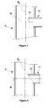
- the device comprises injection tubes 11 disposed substantially orthogonal to the winding plane P e and having an inner section constituting the pass section S i of said orifices 8.
- the injection tube 11 has an outer portion whose length L t can be between 0 mm, in other words, it is in this case a simple drilling of the duct, up to 20 mm.
- the thickness of the injection tube can vary from 2 to 5 mm.
- Its output section S i varies according to the number of injection orifice disposed on the supply duct.
- the injection tubes 11 advantageously comprise a portion 12 projecting inside the conduit 5 supply.
- the injection tube 11 can be protruding up to a maximum of 1 mm.
- the injection tube 11 may also be slightly convergent in order to accelerate the flow of NH 3 .
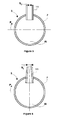
- the protruding portion 12 of the injection tube 11 inside the supply duct 5 may respectively have a shape of half tube, bevel or elbow.
- the ammonia supply duct 5 may have an inside diameter of between 1 and 9 mm and an outside diameter of between 2 and 10 mm, a thickness of 0, 5 mm
Landscapes
- Chemical & Material Sciences (AREA)
- Chemical Kinetics & Catalysis (AREA)
- Engineering & Computer Science (AREA)
- Health & Medical Sciences (AREA)
- Toxicology (AREA)
- Combustion & Propulsion (AREA)
- Mechanical Engineering (AREA)
- General Engineering & Computer Science (AREA)
- Exhaust Gas After Treatment (AREA)
Abstract
Description
- La présente invention se rapporte à un dispositif d'injection de gaz et concerne plus particulièrement le domaine du traitement des polluants par catalyse à l'aide d'un agent réducteur.
- Depuis de nombreuses années, les constructeurs de véhicules automobiles à moteur thermique font beaucoup d'efforts pour réduire l'émission dans l'atmosphère de composés chimiques nuisibles à l'environnement produits par les moteurs thermiques lors de la combustion du carburant.
- Parmi ces composés, on trouve notamment le dioxyde de carbone CO2 ainsi que les oxydes d'azote, principalement le monoxyde NO et le dioxyde NO2 d'azote, désignés ensemble sous l'abréviation NOx. Notons que la production d'oxydes d'azote est plus importante pour les moteurs Diesel que pour les moteurs à essence du fait de leur température de combustion plus élevée.
- Pour limiter l'émission des oxydes d'azote dans l'atmosphère, une solution actuellement utilisée consiste à placer sur la ligne d'échappement du véhicule un système de traitement des NOx, appelé système SCR (« Selective Catalytic Reduction »), ayant pour fonction de réduire chimiquement les oxydes d'azote en molécules de di-azote et en vapeur d'eau au moyen d'un agent réducteur. En pratique, l'agent réducteur est injecté dans la ligne d'échappement en amont d'un catalyseur spécifique SCR dans lequel se produit la réaction de réduction.
- On distingue deux voies SCR, l'une avec la solution aqueuse d'urée et l'autre avec de l'ammoniac, NH3, gazeux.
- La SCR avec urée a été préalablement favorisée pour des raisons d'implantation véhicule. La solution aqueuse d'urée nécessitant un réservoir, le circuit d'alimentation du liquide est relativement simple. Cette voie a par contre l'inconvénient de nécessiter un ensemble de processus physico-chimiques séquentiels longs : l'injection de la solution aqueuse d'urée, l'atomisation du spray d'urée en gouttes puis gouttelettes, l'évaporation et la décomposition chimique de ces gouttelettes en NH3 et enfin le mélange du NH3 avec les gaz d'échappement. Par ailleurs, étant donné l'espace disponible dans la ligne d'échappement pour les phénomènes injection/mélange, la solution SCR avec la solution aqueuse d'urée complique fortement l'homogénéisation de réducteur avec l'oxydant.
- L'autre voie explorée est la SCR avec de l'ammoniac, NH3 gazeux. Dans ce cas, le NH3 est injecté sous forme de gaz directement dans les gaz d'échappement où il doit ensuite s'y mélanger.
- Il est connu de laisser une distance adéquate entre l'injecteur d'agent réducteur et le catalyseur SCR pour permettre l'obtention d'un mélange homogène le plus achevé possible entre les gaz d'échappement et l'agent réducteur.
- Afin d'améliorer l'homogénéité de ce mélange et de raccourcir la distance nécessaire à l'homogénéisation, il est connu d'avoir recours à un mélangeur dit statique, c'est-à-dire sans pièce mobile, positionné à l'intérieur du conduit d'échappement, entre le point d'injection d'agent réducteur dans les gaz d'échappement et l'entrée du catalyseur SCR.
- Afin d'améliorer l'homogénéité de ce mélange et de raccourcir la distance nécessaire à l'homogénéisation, il est aussi connu de multiplier les points d'injection de l'agent réducteur en amont du catalyseur SCR.
- On connait en particulier du document
US2008060352 un dispositif pour la réduction des oxydes d'azote contenus dans des gaz d'échappement produits par un moteur à combustion interne. Le dispositif comprend un injecteur pour injecter un agent réducteur. L'injecteur présente notamment une forme en spirale et comprend une pluralité d'orifices d'injection disposés sur sa longueur. Cependant un tel dispositif n'est pas suffisant pour réellement permettre une diffusion homogène de l'agent réducteur et par conséquent la préparation efficace et l'obtention sur une courte distance axiale d'un mélange homogène entre les gaz d'échappement et l'agent réducteur. - L'invention a pour but de pallier l'inconvénient de l'art antérieur en proposant un nouveau dispositif apte à permettre une diffusion et une répartition homogène de gaz.
- L'invention concerne donc un dispositif d'injection de gaz comprenant un conduit d'amenée de gaz comportant une partie terminale formant une spirale selon un plan d'enroulement et comportant une pluralité d'orifices d'injection distribués sur la longueur de la partie terminale et comprenant chacun un axe d'injection sensiblement orthogonal au plan d'enroulement, caractérisé en ce que chacun des orifices d'injection présente une section de passage définie de manière à permettre le passage d'un même débit de gaz à travers les dits orifices d'injection.
- De manière simple, la section de passage peut être déterminée par la relation :

dans laquelle : - S est la section intérieure de passage du conduit d'amenée de gaz,
- i est un indice attribué à l'orifice d'injection considéré, i variant de 1 à n dans le sens de l'écoulement du gaz dans le conduit d'amenée et où n est le nombre total d'orifices d'injection.
- On équilibre ainsi les débits de gaz entre les différents orifices d'injection, ce qui permet d'avoir un flux de gaz injecté mieux réparti dans le plan d'enroulement de la partie terminale.
- Par ailleurs, l'invention peut comporter l'une ou plusieurs des caractéristiques suivantes :
- Dans une variante, la partie terminale du conduit d'amenée en forme de spirale est formée par un assemblage de tubes rectilignes.
- De préférence, le dispositif de l'invention comprend des tubes d'injection disposés sensiblement orthogonalement au plan d'enroulement au niveau des orifices d'injection et présentant une section intérieure constituant la section de passage desdits orifices.
- De préférence encore, les tubes d'injection comprennent une partie saillante à l'intérieur du conduit d'amenée.
- De préférence encore, la partie saillante du tube d'injection à l'intérieur du conduit d'amenée présente une forme de demi-tube, de coude ou de biseau, afin de limiter les pertes de charge occasionnées par la partie saillante du tube d'injection.
- De préférence, le conduit d'amenée comprend un nombre d'orifice d'injection supérieur à 5.
- Par ailleurs, l'invention a aussi pour objet une ligne d'échappement dans laquelle circule des gaz d'échappement produits par un moteur à combustion interne, ladite ligne comprenant un catalyseur de réduction sélective des oxydes d'azote doté d'une face d'entrée sensiblement perpendiculaire au sens d'écoulement des gaz d'échappement, comprenant au moins un dispositif d'injection de gaz de l'invention, disposé, relativement au sens d'écoulement des gaz d'échappement, en amont du catalyseur de réduction sélective, le plan d'enroulement de partie terminale du dispositif étant sensiblement parallèle à la face d'entrée du catalyseur de réduction sélective et les orifices d'injection orientés vers ladite face d'entrée.
- De préférence, le dispositif d'injection de gaz injecte de l'ammoniac gazeux, qui est un agent réducteur efficace pour la catalyse par réduction sélective des oxydes d'azotes
- De préférence, le dispositif d'injection de gaz est disposé en amont du catalyseur de réduction sélective à une distance comprise entre 10 mm et 60 mm, ce qui permet d'améliore la compacité de l'ensemble.
- D'autres particularités et avantages apparaîtront à la lecture de la description ci-après d'un mode particulier de réalisation, non limitatif de l'invention, faite en référence aux figures dans lesquelles :
- La
figure 1 est une représentation schématique d'une ligne d'échappement comprenant le dispositif d'injection de gaz de l'invention. - La
figure 2 est une vue en coupe selon le plan de coupe A-A référencé enfigure 1 d'un premier mode de réalisation du dispositif d'injection de gaz de l'invention. - La
figure 3 est une représentation schématique d'un second mode de réalisation comprenant deux dispositifs d'injection de gaz de l'invention. - Les
figures 4 ,5, 6 sont des vues schématiques en coupe de variantes de réalisation avec tube d'injection. - Les
figures 7, 8 et9 sont des vues schématiques en coupe de variantes de réalisation avec un tube d'injection et une partie saillante interne au conduit d'amenée respectivement en demi-tube, en biseau, en coude. - La
figure 1 présente une portion de ligne d'échappement de gaz brûlés produits par un moteur à combustion interne. La ligne d'échappement comprend un conduit 1 principal, d'axe central XX, dans lequel circule un flux 2 de gaz brûlés dit flux gazeux principal et raccordé à un catalyseur 3 de réduction sélective (ou SCR), pour la réduction des oxydes d'azote NOx présents dans les gaz d'échappement, par réaction catalytique sélective entre les NOx et un agent réducteur. Par agent réducteur, il convient d'entendre un agent pouvant réagir chimiquement avec des polluants pour les transformer en des produits moins polluants. Le catalyseur 3 est doté d'une face d'entrée 4 sensiblement perpendiculaire au sens d'écoulement des gaz d'échappement. - En amont du catalyseur 3 SCR, relativement au sens d'écoulement des gaz d'échappement, est disposé un dispositif d'injection de gaz comprenant un conduit 5 d'amenée d'un flux 6 d'agent réducteur, en l'occurrence de l'ammoniac gazeux, NH3. Le conduit d'amenée 5 traverse le conduit 1 principal. De préférence, le dispositif d'injection de gaz est disposé en amont du catalyseur 3 de réduction sélective à une distance D comprise entre 10 mm et 60 mm.
- La
figure 2 présente une vue en coupe selon le plan de coupe A-A référencé enfigure 1 passant par l'axe central du conduit d'amenée 5. Le conduit d'amenée 5 comporte une partie terminale 7 ayant la forme générale d'une spirale enroulée plate selon un plan d'enroulement Pe identique au plan de coupe A-A référencé enfigure 1 . La partie terminale 7 en spirale comporte une pluralité d'orifices 8 d'injection distribués sur longueur de la partie terminale. Les orifices 8 d'injection sont disposés sur la partie terminale 7 de manière à présenter chacun un axe d'injection 1 sensiblement orthogonal au plan d'enroulement Pe, tel qu'illustré enfigure 1 . - Dans le mode de réalisation présenté en
figure 2 , il est prévu que la partie terminale 7 du conduit 5 d'amenée en forme de spirale soit avantageusement formé par un assemblage de tubes rectilignes. Les tubes 8 rectilignes peuvent être soudés entre eux. Cet ensemble de tubes 8 cylindriques servent de générateur de turbulence pour les gaz d'échappement. Des tubes extérieurement cylindriques permettent de limiter les pertes de charges et de générer une turbulence la plus homogène possible. - L'invention permet d'intensifier le mélange entre les gaz d'échappement et le NH3 gazeux en créant de multiples zones d'injection et de mélange de l'ammoniac gazeux avec les gaz d'échappement. Les zones 10 d'injection et de mélange sont représentées fictivement sur la
figure 2 sous forme d'hexaèdres réguliers. - Comme le montre encore la
figure 1 , le plan d'enroulement Pe de la partie terminale 7 du dispositif est sensiblement parallèle à la face 4 d'entrée du catalyseur 3 de réduction sélective et les orifices 8 d'injection sont orientés vers ladite face 4 d'entrée. - Dans le mode de réalisation présenté en
figure 2 , l'ensemble des tubes 8 cylindriques de sont disposés afin de joindre les centres de chacun des hexaèdres réguliers pour former un réseau de tubes et permettant de faire un maillage le plus régulier possible de la section de passage des gaz d'échappement. - Concerne la partie terminale 7 du conduit d'amenée 5, il est prévu d'avoir une répartition homogène des orifices 8 d'injection dans le plan d'enroulement Pe afin d'assurer un mélange le plus homogène possible entre les gaz d'échappement et l'ammoniac sous forme gazeuse.
- De plus, conformément à l'invention, il est prévu d'adapter la section de chaque orifice 8 d'injection d'ammoniac pour obtenir un débit d'injection d'ammoniac sensiblement identique à travers chacun des orifices 8 d'injection. Les orifices 8 d'injection étant situés dans le présent exemple sensiblement au niveau de coudes, leur diamètre augmente au fur et à mesure de la longueur du parcours entre l'entrée de l'ammoniac jusqu'à l'orifice d'injection considéré.
- Soit Q le débit total du flux 6 d'ammoniac et n le nombre total d'orifices d'injection, on veut avoir le même débit Q' à chaque orifice 8 d'injection à savoir Q'=Q/n. Or chaque orifice 8 d'injection crée une intersection où le débit se divise en deux entre la suite du réseau et l'orifice 8 d'injection.
- La répartition du débit entre le réseau et le trou dépend de la section intérieure de passage du conduit 5 d'amenée d'ammoniac et de l'orifice 8 d'injection. Ainsi, en attribuant un indice i aux orifices d'injection, i variant de 1 à n dans le sens de l'écoulement du flux 6 d'ammoniac gazeux, avec n le nombre total d'orifices 8 d'injection, en faisant l'hypothèse d'une perte de charge uniforme dans le conduit 5 d'amenée, le débit avant l'orifice d'injection i, noté Qi-1, est égal au débit de l'orifice d'injection Q' et au débit après l'orifice d'injection i, noté Qi , soit

- Après développements il vient :

- En appliquant le théorème de Bernoulli à chaque intersection, on obtient la relation :

- Avec Si, la section de passage de l'orifice 8 d'injection d'indice i, soit finalement :

- On peut avantageusement affiner la détermination des sections Si de passage en prenant en compte de paramètres supplémentaires influençant l'écoulement de gaz dans le conduit 5 d'amenée et en particulier les pertes de charge.
- Les gaz d'échappement composés des oxydes d'azote produits par la combustion heurtent les tubes cylindriques du conduit 5 d'amenée, ce qui va générer dans son sillage une turbulence d'environ 5 % de la vitesse d'écoulement des gaz d'échappement. En aval, l'ammoniac gazeux va être injecté par tous les orifices 8 d'injection. L'ammoniac va donc être injecté dans des régions où de la turbulence a été créée, ce qui va permettre d'améliorer l'homogénéisation du mélange gaz d'échappement et ammoniac gazeux. Au niveau global, avec une multitude de points d'injection, l'homogénéisation du mélange sera encore plus efficace.
- De préférence, le conduit 5 d'amenée d'ammoniac comprend un nombre d'orifice 8 d'injection supérieur à 5. De préférence encore, le conduit 5 d'amenée d'ammoniac comprend un nombre d'orifice 8 d'injection inférieur à 20.
- En outre la distance D peut être ajustée en fonction du dépend du nombre total d'orifices d'injection. En effet, plus le nombre n d'orifice d'injection est élevé, plus la distance D peut être courte. La distance D peut être évaluée à l'aide d'abaques qui donnent une distance de mélange adimensionnée entre deux flux en fonction des débits des deux flux en question. Ainsi pour n=5 il est apparu qu'une distance D de 6 cm est nécessaire pour une homogénéisation parfaite. La distance D diminue sensiblement linéairement avec le nombre n d'orifices 8 d'injection, toutefois au-delà de n=20 il semble plus difficile d'assurer un équilibrage des débits.
- Dans un second mode de réalisation tel que présenté en
figure 3 , le dispositif d'injection peut comprendre plusieurs conduit 5 d'amenée et chacun des conduits 5 comprend quelques orifices d'injection d'ammoniac. - L'orifice d'injection peut avoir d'autres formes de section qu'un simple cercle, comme une ellipse pour mieux diriger le flux de NH3 dans la largeur.
- Dans une variante présentée en coupe sur la
figure 4 , le dispositif comprend des tubes 11 d'injection disposés sensiblement orthogonalement au plan d'enroulement Pe et présentant une section intérieure constituant la section de passe Si desdits orifices 8. Le tube 11 d'injection présente une partie extérieure dont la longueur Lt peut être comprise entre 0 mm, autrement dit, il s'agit dans ce cas d'un simple perçage du conduit, jusqu'à 20 mm. L'épaisseur du tube d'injection peut varier de 2 à 5 mm. Sa section de sortie Si varie en fonction du nombre d'orifice d'injection disposé sur le conduit d'amenée. - Dans une autre variante présentée en coupe sur la
figure 5 , les tubes 11 d'injection comprennent avantageusement une partie 12 saillante à l'intérieur du conduit 5 d'amenée. Le tube 11 d'injection peut être saillant jusqu'à un maximum de 1 mm. - Dans une autre variante présentée en coupe sur la
figure 6 , le tube 11 d'injection peut également être légèrement convergent afin d'accélérer le flux de NH3. - Dans d'autres variante présentés en coupe aux
figures 7 à 9 , afin d'éviter les pertes de charge dans la partie 7 terminale du conduit 5 d'amenée de NH3, la partie 12 saillante du tube 11 d'injection à l'intérieur du conduit 5 d'amenée peut présenter respectivement une forme de demi-tube, de biseau ou de coude. - Dans le cas où le conduit 5 d'amenée d'ammoniac est un tube cylindrique à l'intérieur, le conduit 5 d'amenée peut voir un diamètre intérieur compris entre 1 et 9 mm et un diamètre extérieur compris entre 2 et 10 mm soit une épaisseur de 0, 5 mm
Claims (9)
- Dispositif d'injection de gaz comprenant un conduit (5) d'amenée de gaz comportant une partie (7) terminale formant une spirale selon un plan (Pe) d'enroulement et comportant une pluralité d'orifices (8) d'injection distribués sur la longueur de la partie (7) terminale et comprenant chacun un axe d'injection (Ai) sensiblement orthogonal au plan (Pe) d'enroulement, caractérisé en ce que chacun des orifices (8) d'injection présente une section (Si) de passage définie de manière à permettre le passage d'un même débit (Q') de gaz à travers les dits orifices (8) d'injection.
- Dispositif selon la revendication 1, caractérisé en ce que la partie (7) terminale du conduit (5) d'amenée en forme de spirale est formée par un assemblage de tubes (9) rectilignes.
- Dispositif selon l'une quelconque des revendications précédentes, caractérisé en ce qu'il comprend des tubes (11) d'injection disposés sensiblement orthogonalement au plan (Pe) d'enroulement au niveau des orifices (8) d'injection et présentant une section intérieure constituant la section (Si) de passage desdits orifices.
- Dispositif selon la revendication 3, caractérisé en ce que les tubes (11) d'injection comprennent une partie (12) saillante à l'intérieur du conduit (5) d'amenée.
- Dispositif selon la revendication 4, caractérisé en ce que la partie (12) saillante du tube (11) d'injection à l'intérieur du conduit (5) d'amenée présente une forme de demi-tube, de coude ou de biseau.
- Dispositif selon l'une quelconque des revendications précédentes caractérisé en ce que le conduit (5) d'amenée comprend un nombre d'orifice d'injection supérieur à 5.
- Ligne d'échappement dans laquelle circule des gaz d'échappement produits par un moteur à combustion interne, ladite ligne comprenant un catalyseur (3) de réduction sélective des oxydes d'azote doté d'une face (4) d'entrée sensiblement perpendiculaire au sens d'écoulement des gaz d'échappement, caractérisée en ce qu'elle comprend au moins un dispositif d'injection de gaz selon l'une quelconque des revendications 1 à 6 disposé, relativement au sens d'écoulement des gaz d'échappement, en amont du catalyseur (3) de réduction sélective, le plan (Pe) d'enroulement de partie (7) terminale du dispositif étant sensiblement parallèle à la face (4) d'entrée du catalyseur (3) de réduction sélective et les orifices (8) d'injection orientés vers ladite face (4) d'entrée.
- Ligne d'échappement selon la revendication 7, caractérisé en ce le dispositif d'injection de gaz injecte de l'ammoniac gazeux.
- Ligne d'échappement selon la revendication 7 ou la revendication 8, caractérisé en ce que le dispositif d'injection de gaz est disposé en amont du catalyseur (3) de réduction sélective à une distance (D) comprise entre 10 mm et 60 mm.
Applications Claiming Priority (1)
| Application Number | Priority Date | Filing Date | Title |
|---|---|---|---|
| FR1050421A FR2955610B1 (fr) | 2010-01-22 | 2010-01-22 | Dispositif d'injection de gaz et ligne d'echappement comprenant un tel dispositif |
Publications (1)
| Publication Number | Publication Date |
|---|---|
| EP2348204A1 true EP2348204A1 (fr) | 2011-07-27 |
Family
ID=42629553
Family Applications (1)
| Application Number | Title | Priority Date | Filing Date |
|---|---|---|---|
| EP10195151A Withdrawn EP2348204A1 (fr) | 2010-01-22 | 2010-12-15 | Dispositif d'injection de gaz et ligne d'échappement comprenant un tel dispositif |
Country Status (2)
| Country | Link |
|---|---|
| EP (1) | EP2348204A1 (fr) |
| FR (1) | FR2955610B1 (fr) |
Cited By (4)
| Publication number | Priority date | Publication date | Assignee | Title |
|---|---|---|---|---|
| WO2013000640A1 (fr) * | 2011-06-28 | 2013-01-03 | Robert Bosch Gmbh | Dispositif et procédé d'introduction d'un réducteur dans une ligne d'échappement |
| WO2013117230A1 (fr) * | 2012-02-09 | 2013-08-15 | Toyota Motor Europe Nv/Sa | Injecteur d'agent de réduction |
| EP3364004A4 (fr) * | 2015-10-16 | 2018-08-29 | Yanmar Co., Ltd. | Dispositif de purification de gaz d'échappement pour navire |
| US10794252B1 (en) | 2019-04-18 | 2020-10-06 | Faurecia Emissions Control Technologies, Usa, Llc | Direct spray exhaust mixer system |
Citations (5)
| Publication number | Priority date | Publication date | Assignee | Title |
|---|---|---|---|---|
| US5431894A (en) * | 1992-08-18 | 1995-07-11 | Mitsubishi Jukogyo Kabushiki Kaisha | Prevention of ammonia decomposition |
| US20080060352A1 (en) | 2004-10-11 | 2008-03-13 | Volvo Lastvagnar Ab | System and Method for Reduction of Nitrogen Oxides from Exhaust Gases Generated by a Lean-Burn Combustion Engine |
| US20080193353A1 (en) * | 2007-02-09 | 2008-08-14 | Sebastian Hirschberg | Exhaust gas cleaning system |
| EP1975381A1 (fr) * | 2006-01-06 | 2008-10-01 | MITSUI ENGINEERING & SHIPBUILDING CO., LTD | Procede de denitrification de gaz d'echappement et appareil correspondant |
| US20090257924A1 (en) * | 2006-01-27 | 2009-10-15 | Pierburg Gmbh | Device for the reduction of nitrogen oxides in the exhaust gas of internal combustion engines |
-
2010
- 2010-01-22 FR FR1050421A patent/FR2955610B1/fr not_active Expired - Fee Related
- 2010-12-15 EP EP10195151A patent/EP2348204A1/fr not_active Withdrawn
Patent Citations (5)
| Publication number | Priority date | Publication date | Assignee | Title |
|---|---|---|---|---|
| US5431894A (en) * | 1992-08-18 | 1995-07-11 | Mitsubishi Jukogyo Kabushiki Kaisha | Prevention of ammonia decomposition |
| US20080060352A1 (en) | 2004-10-11 | 2008-03-13 | Volvo Lastvagnar Ab | System and Method for Reduction of Nitrogen Oxides from Exhaust Gases Generated by a Lean-Burn Combustion Engine |
| EP1975381A1 (fr) * | 2006-01-06 | 2008-10-01 | MITSUI ENGINEERING & SHIPBUILDING CO., LTD | Procede de denitrification de gaz d'echappement et appareil correspondant |
| US20090257924A1 (en) * | 2006-01-27 | 2009-10-15 | Pierburg Gmbh | Device for the reduction of nitrogen oxides in the exhaust gas of internal combustion engines |
| US20080193353A1 (en) * | 2007-02-09 | 2008-08-14 | Sebastian Hirschberg | Exhaust gas cleaning system |
Cited By (4)
| Publication number | Priority date | Publication date | Assignee | Title |
|---|---|---|---|---|
| WO2013000640A1 (fr) * | 2011-06-28 | 2013-01-03 | Robert Bosch Gmbh | Dispositif et procédé d'introduction d'un réducteur dans une ligne d'échappement |
| WO2013117230A1 (fr) * | 2012-02-09 | 2013-08-15 | Toyota Motor Europe Nv/Sa | Injecteur d'agent de réduction |
| EP3364004A4 (fr) * | 2015-10-16 | 2018-08-29 | Yanmar Co., Ltd. | Dispositif de purification de gaz d'échappement pour navire |
| US10794252B1 (en) | 2019-04-18 | 2020-10-06 | Faurecia Emissions Control Technologies, Usa, Llc | Direct spray exhaust mixer system |
Also Published As
| Publication number | Publication date |
|---|---|
| FR2955610B1 (fr) | 2012-01-13 |
| FR2955610A1 (fr) | 2011-07-29 |
Similar Documents
| Publication | Publication Date | Title |
|---|---|---|
| US10188994B2 (en) | Method, apparatus and system for aftertreatment of exhaust gas | |
| US10273855B2 (en) | Exhaust aftertreatment system having mixer assembly | |
| EP2551482B1 (fr) | Ensemble coude de post-traitement des gaz d'echappement d'un moteur à combustion comportant un convergent interne | |
| RU2557055C2 (ru) | Способ дозирования восстановителя на основе мочевины в поток отработавшего газа | |
| EP2500538B1 (fr) | Ensemble compact coudé de post-traitement de gaz d'échappement doté d'un bossage formant mélangeur de réducteur scr | |
| EP2198135B1 (fr) | Dispositif de traitement des gaz d'échappement d'un moteur à combustion interne capable de fonctionner en conditions pauvres | |
| US10252225B2 (en) | Method, apparatus and mixing device for evenly mixing reactant to exhaust gas flow | |
| US20080022663A1 (en) | System and method for dispensing an aqueous urea solution into an exhaust gas stream | |
| CN203452872U (zh) | 用于排气催化器的入流室和用于机动车的排气净化系统 | |
| JP6297294B2 (ja) | 排出ガス流れに液体を噴射するための装置および排出ガス後処理システム | |
| KR20010034449A (ko) | 내연 기관의 배기관 섹션 내로 환원제를 운반하기 위한 장치 | |
| FR3110634A1 (fr) | Dispositif de mélange, ligne d’échappement et véhicule associés | |
| CN104033218A (zh) | 用于排气净化系统的催化器的入流室 | |
| EP2252779A1 (fr) | Dispositif de dosage pour la reduction des substances toxiques dans les gaz d'echappement | |
| JP2008031996A (ja) | 流体投与装置 | |
| EP1191995A1 (fr) | Dispositif pour solliciter des gaz en ecoulement avec un agent reactif | |
| FR2977913A1 (fr) | Dispositif d'introduction et de melange d'un liquide dans une portion d'un conduit | |
| FR2955610A1 (fr) | Dispositif d'injection de gaz et ligne d'echappement comprenant un tel dispositif | |
| FR2945576A1 (fr) | Melangeur, dispositif de depollution et ligne d'echappement equipee de ce melangeur. | |
| FR2955266A1 (fr) | Dispositif pour le melange entre un flux gazeux principal et un flux gazeux auxiliaire | |
| US20090100827A1 (en) | Exhaust gas purification apparatus for internal combustion engine | |
| FR2939890A3 (fr) | Dispositif d'echantillonnage d'un gaz ou d'un aerosol, notamment d'un gaz de combustion automobile | |
| FR2956698A1 (fr) | Element de ligne d'echappement et ligne d'echappement comportant un tel element d'echappement | |
| WO2011095734A1 (fr) | Ligne d'echappement pour un moteur a combustion interne | |
| EP3321483B1 (fr) | Injecteur de fluide d'échappement diesel |
Legal Events
| Date | Code | Title | Description |
|---|---|---|---|
| PUAI | Public reference made under article 153(3) epc to a published international application that has entered the european phase |
Free format text: ORIGINAL CODE: 0009012 |
|
| AK | Designated contracting states |
Kind code of ref document: A1 Designated state(s): AL AT BE BG CH CY CZ DE DK EE ES FI FR GB GR HR HU IE IS IT LI LT LU LV MC MK MT NL NO PL PT RO RS SE SI SK SM TR |
|
| AX | Request for extension of the european patent |
Extension state: BA ME |
|
| 17P | Request for examination filed |
Effective date: 20111220 |
|
| RIC1 | Information provided on ipc code assigned before grant |
Ipc: F01N 3/20 20060101AFI20130311BHEP Ipc: F01N 3/36 20060101ALI20130311BHEP Ipc: B01F 3/04 20060101ALI20130311BHEP Ipc: B01D 53/86 20060101ALI20130311BHEP Ipc: B01F 5/04 20060101ALI20130311BHEP |
|
| 17Q | First examination report despatched |
Effective date: 20150220 |
|
| GRAP | Despatch of communication of intention to grant a patent |
Free format text: ORIGINAL CODE: EPIDOSNIGR1 |
|
| INTG | Intention to grant announced |
Effective date: 20150715 |
|
| STAA | Information on the status of an ep patent application or granted ep patent |
Free format text: STATUS: THE APPLICATION IS DEEMED TO BE WITHDRAWN |
|
| 18D | Application deemed to be withdrawn |
Effective date: 20151126 |