EP2347878A2 - Verfahren zur Herstellung von peroxidvernetzten Polyethylenrohren in einer Extrusionslinie - Google Patents
Verfahren zur Herstellung von peroxidvernetzten Polyethylenrohren in einer Extrusionslinie Download PDFInfo
- Publication number
- EP2347878A2 EP2347878A2 EP10015646A EP10015646A EP2347878A2 EP 2347878 A2 EP2347878 A2 EP 2347878A2 EP 10015646 A EP10015646 A EP 10015646A EP 10015646 A EP10015646 A EP 10015646A EP 2347878 A2 EP2347878 A2 EP 2347878A2
- Authority
- EP
- European Patent Office
- Prior art keywords
- heating
- heating section
- cross
- extension
- extrusion line
- Prior art date
- Legal status (The legal status is an assumption and is not a legal conclusion. Google has not performed a legal analysis and makes no representation as to the accuracy of the status listed.)
- Granted
Links
Images
Classifications
-
- B—PERFORMING OPERATIONS; TRANSPORTING
- B29—WORKING OF PLASTICS; WORKING OF SUBSTANCES IN A PLASTIC STATE IN GENERAL
- B29C—SHAPING OR JOINING OF PLASTICS; SHAPING OF MATERIAL IN A PLASTIC STATE, NOT OTHERWISE PROVIDED FOR; AFTER-TREATMENT OF THE SHAPED PRODUCTS, e.g. REPAIRING
- B29C48/00—Extrusion moulding, i.e. expressing the moulding material through a die or nozzle which imparts the desired form; Apparatus therefor
- B29C48/001—Combinations of extrusion moulding with other shaping operations
- B29C48/0018—Combinations of extrusion moulding with other shaping operations combined with shaping by orienting, stretching or shrinking, e.g. film blowing
-
- B—PERFORMING OPERATIONS; TRANSPORTING
- B29—WORKING OF PLASTICS; WORKING OF SUBSTANCES IN A PLASTIC STATE IN GENERAL
- B29C—SHAPING OR JOINING OF PLASTICS; SHAPING OF MATERIAL IN A PLASTIC STATE, NOT OTHERWISE PROVIDED FOR; AFTER-TREATMENT OF THE SHAPED PRODUCTS, e.g. REPAIRING
- B29C35/00—Heating, cooling or curing, e.g. crosslinking or vulcanising; Apparatus therefor
- B29C35/02—Heating or curing, e.g. crosslinking or vulcanizing during moulding, e.g. in a mould
- B29C35/08—Heating or curing, e.g. crosslinking or vulcanizing during moulding, e.g. in a mould by wave energy or particle radiation
- B29C35/10—Heating or curing, e.g. crosslinking or vulcanizing during moulding, e.g. in a mould by wave energy or particle radiation for articles of indefinite length
-
- B—PERFORMING OPERATIONS; TRANSPORTING
- B29—WORKING OF PLASTICS; WORKING OF SUBSTANCES IN A PLASTIC STATE IN GENERAL
- B29C—SHAPING OR JOINING OF PLASTICS; SHAPING OF MATERIAL IN A PLASTIC STATE, NOT OTHERWISE PROVIDED FOR; AFTER-TREATMENT OF THE SHAPED PRODUCTS, e.g. REPAIRING
- B29C48/00—Extrusion moulding, i.e. expressing the moulding material through a die or nozzle which imparts the desired form; Apparatus therefor
- B29C48/001—Combinations of extrusion moulding with other shaping operations
- B29C48/0017—Combinations of extrusion moulding with other shaping operations combined with blow-moulding or thermoforming
-
- B—PERFORMING OPERATIONS; TRANSPORTING
- B29—WORKING OF PLASTICS; WORKING OF SUBSTANCES IN A PLASTIC STATE IN GENERAL
- B29C—SHAPING OR JOINING OF PLASTICS; SHAPING OF MATERIAL IN A PLASTIC STATE, NOT OTHERWISE PROVIDED FOR; AFTER-TREATMENT OF THE SHAPED PRODUCTS, e.g. REPAIRING
- B29C48/00—Extrusion moulding, i.e. expressing the moulding material through a die or nozzle which imparts the desired form; Apparatus therefor
- B29C48/001—Combinations of extrusion moulding with other shaping operations
- B29C48/0022—Combinations of extrusion moulding with other shaping operations combined with cutting
-
- B—PERFORMING OPERATIONS; TRANSPORTING
- B29—WORKING OF PLASTICS; WORKING OF SUBSTANCES IN A PLASTIC STATE IN GENERAL
- B29C—SHAPING OR JOINING OF PLASTICS; SHAPING OF MATERIAL IN A PLASTIC STATE, NOT OTHERWISE PROVIDED FOR; AFTER-TREATMENT OF THE SHAPED PRODUCTS, e.g. REPAIRING
- B29C48/00—Extrusion moulding, i.e. expressing the moulding material through a die or nozzle which imparts the desired form; Apparatus therefor
- B29C48/03—Extrusion moulding, i.e. expressing the moulding material through a die or nozzle which imparts the desired form; Apparatus therefor characterised by the shape of the extruded material at extrusion
- B29C48/07—Flat, e.g. panels
- B29C48/08—Flat, e.g. panels flexible, e.g. films
-
- B—PERFORMING OPERATIONS; TRANSPORTING
- B29—WORKING OF PLASTICS; WORKING OF SUBSTANCES IN A PLASTIC STATE IN GENERAL
- B29C—SHAPING OR JOINING OF PLASTICS; SHAPING OF MATERIAL IN A PLASTIC STATE, NOT OTHERWISE PROVIDED FOR; AFTER-TREATMENT OF THE SHAPED PRODUCTS, e.g. REPAIRING
- B29C48/00—Extrusion moulding, i.e. expressing the moulding material through a die or nozzle which imparts the desired form; Apparatus therefor
- B29C48/03—Extrusion moulding, i.e. expressing the moulding material through a die or nozzle which imparts the desired form; Apparatus therefor characterised by the shape of the extruded material at extrusion
- B29C48/09—Articles with cross-sections having partially or fully enclosed cavities, e.g. pipes or channels
-
- B—PERFORMING OPERATIONS; TRANSPORTING
- B29—WORKING OF PLASTICS; WORKING OF SUBSTANCES IN A PLASTIC STATE IN GENERAL
- B29C—SHAPING OR JOINING OF PLASTICS; SHAPING OF MATERIAL IN A PLASTIC STATE, NOT OTHERWISE PROVIDED FOR; AFTER-TREATMENT OF THE SHAPED PRODUCTS, e.g. REPAIRING
- B29C48/00—Extrusion moulding, i.e. expressing the moulding material through a die or nozzle which imparts the desired form; Apparatus therefor
- B29C48/25—Component parts, details or accessories; Auxiliary operations
- B29C48/88—Thermal treatment of the stream of extruded material, e.g. cooling
- B29C48/90—Thermal treatment of the stream of extruded material, e.g. cooling with calibration or sizing, i.e. combined with fixing or setting of the final dimensions of the extruded article
- B29C48/901—Thermal treatment of the stream of extruded material, e.g. cooling with calibration or sizing, i.e. combined with fixing or setting of the final dimensions of the extruded article of hollow bodies
-
- B—PERFORMING OPERATIONS; TRANSPORTING
- B29—WORKING OF PLASTICS; WORKING OF SUBSTANCES IN A PLASTIC STATE IN GENERAL
- B29C—SHAPING OR JOINING OF PLASTICS; SHAPING OF MATERIAL IN A PLASTIC STATE, NOT OTHERWISE PROVIDED FOR; AFTER-TREATMENT OF THE SHAPED PRODUCTS, e.g. REPAIRING
- B29C48/00—Extrusion moulding, i.e. expressing the moulding material through a die or nozzle which imparts the desired form; Apparatus therefor
- B29C48/25—Component parts, details or accessories; Auxiliary operations
- B29C48/88—Thermal treatment of the stream of extruded material, e.g. cooling
- B29C48/90—Thermal treatment of the stream of extruded material, e.g. cooling with calibration or sizing, i.e. combined with fixing or setting of the final dimensions of the extruded article
- B29C48/908—Thermal treatment of the stream of extruded material, e.g. cooling with calibration or sizing, i.e. combined with fixing or setting of the final dimensions of the extruded article characterised by calibrator surface, e.g. structure or holes for lubrication, cooling or venting
-
- B—PERFORMING OPERATIONS; TRANSPORTING
- B29—WORKING OF PLASTICS; WORKING OF SUBSTANCES IN A PLASTIC STATE IN GENERAL
- B29C—SHAPING OR JOINING OF PLASTICS; SHAPING OF MATERIAL IN A PLASTIC STATE, NOT OTHERWISE PROVIDED FOR; AFTER-TREATMENT OF THE SHAPED PRODUCTS, e.g. REPAIRING
- B29C48/00—Extrusion moulding, i.e. expressing the moulding material through a die or nozzle which imparts the desired form; Apparatus therefor
- B29C48/25—Component parts, details or accessories; Auxiliary operations
- B29C48/88—Thermal treatment of the stream of extruded material, e.g. cooling
- B29C48/91—Heating, e.g. for cross linking
-
- B—PERFORMING OPERATIONS; TRANSPORTING
- B29—WORKING OF PLASTICS; WORKING OF SUBSTANCES IN A PLASTIC STATE IN GENERAL
- B29C—SHAPING OR JOINING OF PLASTICS; SHAPING OF MATERIAL IN A PLASTIC STATE, NOT OTHERWISE PROVIDED FOR; AFTER-TREATMENT OF THE SHAPED PRODUCTS, e.g. REPAIRING
- B29C48/00—Extrusion moulding, i.e. expressing the moulding material through a die or nozzle which imparts the desired form; Apparatus therefor
- B29C48/25—Component parts, details or accessories; Auxiliary operations
- B29C48/88—Thermal treatment of the stream of extruded material, e.g. cooling
- B29C48/91—Heating, e.g. for cross linking
- B29C48/9105—Heating, e.g. for cross linking of hollow articles
-
- B—PERFORMING OPERATIONS; TRANSPORTING
- B29—WORKING OF PLASTICS; WORKING OF SUBSTANCES IN A PLASTIC STATE IN GENERAL
- B29C—SHAPING OR JOINING OF PLASTICS; SHAPING OF MATERIAL IN A PLASTIC STATE, NOT OTHERWISE PROVIDED FOR; AFTER-TREATMENT OF THE SHAPED PRODUCTS, e.g. REPAIRING
- B29C48/00—Extrusion moulding, i.e. expressing the moulding material through a die or nozzle which imparts the desired form; Apparatus therefor
- B29C48/25—Component parts, details or accessories; Auxiliary operations
- B29C48/88—Thermal treatment of the stream of extruded material, e.g. cooling
- B29C48/911—Cooling
-
- B—PERFORMING OPERATIONS; TRANSPORTING
- B29—WORKING OF PLASTICS; WORKING OF SUBSTANCES IN A PLASTIC STATE IN GENERAL
- B29C—SHAPING OR JOINING OF PLASTICS; SHAPING OF MATERIAL IN A PLASTIC STATE, NOT OTHERWISE PROVIDED FOR; AFTER-TREATMENT OF THE SHAPED PRODUCTS, e.g. REPAIRING
- B29C48/00—Extrusion moulding, i.e. expressing the moulding material through a die or nozzle which imparts the desired form; Apparatus therefor
- B29C48/25—Component parts, details or accessories; Auxiliary operations
- B29C48/92—Measuring, controlling or regulating
-
- B—PERFORMING OPERATIONS; TRANSPORTING
- B29—WORKING OF PLASTICS; WORKING OF SUBSTANCES IN A PLASTIC STATE IN GENERAL
- B29C—SHAPING OR JOINING OF PLASTICS; SHAPING OF MATERIAL IN A PLASTIC STATE, NOT OTHERWISE PROVIDED FOR; AFTER-TREATMENT OF THE SHAPED PRODUCTS, e.g. REPAIRING
- B29C55/00—Shaping by stretching, e.g. drawing through a die; Apparatus therefor
- B29C55/22—Shaping by stretching, e.g. drawing through a die; Apparatus therefor of tubes
-
- B—PERFORMING OPERATIONS; TRANSPORTING
- B29—WORKING OF PLASTICS; WORKING OF SUBSTANCES IN A PLASTIC STATE IN GENERAL
- B29C—SHAPING OR JOINING OF PLASTICS; SHAPING OF MATERIAL IN A PLASTIC STATE, NOT OTHERWISE PROVIDED FOR; AFTER-TREATMENT OF THE SHAPED PRODUCTS, e.g. REPAIRING
- B29C35/00—Heating, cooling or curing, e.g. crosslinking or vulcanising; Apparatus therefor
- B29C35/02—Heating or curing, e.g. crosslinking or vulcanizing during moulding, e.g. in a mould
- B29C35/08—Heating or curing, e.g. crosslinking or vulcanizing during moulding, e.g. in a mould by wave energy or particle radiation
- B29C35/0805—Heating or curing, e.g. crosslinking or vulcanizing during moulding, e.g. in a mould by wave energy or particle radiation using electromagnetic radiation
- B29C2035/0822—Heating or curing, e.g. crosslinking or vulcanizing during moulding, e.g. in a mould by wave energy or particle radiation using electromagnetic radiation using IR radiation
-
- B—PERFORMING OPERATIONS; TRANSPORTING
- B29—WORKING OF PLASTICS; WORKING OF SUBSTANCES IN A PLASTIC STATE IN GENERAL
- B29C—SHAPING OR JOINING OF PLASTICS; SHAPING OF MATERIAL IN A PLASTIC STATE, NOT OTHERWISE PROVIDED FOR; AFTER-TREATMENT OF THE SHAPED PRODUCTS, e.g. REPAIRING
- B29C2948/00—Indexing scheme relating to extrusion moulding
- B29C2948/92—Measuring, controlling or regulating
- B29C2948/92009—Measured parameter
- B29C2948/92114—Dimensions
- B29C2948/92123—Diameter or circumference
-
- B—PERFORMING OPERATIONS; TRANSPORTING
- B29—WORKING OF PLASTICS; WORKING OF SUBSTANCES IN A PLASTIC STATE IN GENERAL
- B29C—SHAPING OR JOINING OF PLASTICS; SHAPING OF MATERIAL IN A PLASTIC STATE, NOT OTHERWISE PROVIDED FOR; AFTER-TREATMENT OF THE SHAPED PRODUCTS, e.g. REPAIRING
- B29C2948/00—Indexing scheme relating to extrusion moulding
- B29C2948/92—Measuring, controlling or regulating
- B29C2948/92323—Location or phase of measurement
- B29C2948/92428—Calibration, after-treatment, or cooling zone
-
- B—PERFORMING OPERATIONS; TRANSPORTING
- B29—WORKING OF PLASTICS; WORKING OF SUBSTANCES IN A PLASTIC STATE IN GENERAL
- B29C—SHAPING OR JOINING OF PLASTICS; SHAPING OF MATERIAL IN A PLASTIC STATE, NOT OTHERWISE PROVIDED FOR; AFTER-TREATMENT OF THE SHAPED PRODUCTS, e.g. REPAIRING
- B29C2948/00—Indexing scheme relating to extrusion moulding
- B29C2948/92—Measuring, controlling or regulating
- B29C2948/92504—Controlled parameter
- B29C2948/92514—Pressure
-
- B—PERFORMING OPERATIONS; TRANSPORTING
- B29—WORKING OF PLASTICS; WORKING OF SUBSTANCES IN A PLASTIC STATE IN GENERAL
- B29C—SHAPING OR JOINING OF PLASTICS; SHAPING OF MATERIAL IN A PLASTIC STATE, NOT OTHERWISE PROVIDED FOR; AFTER-TREATMENT OF THE SHAPED PRODUCTS, e.g. REPAIRING
- B29C2948/00—Indexing scheme relating to extrusion moulding
- B29C2948/92—Measuring, controlling or regulating
- B29C2948/92504—Controlled parameter
- B29C2948/9258—Velocity
- B29C2948/9259—Angular velocity
-
- B—PERFORMING OPERATIONS; TRANSPORTING
- B29—WORKING OF PLASTICS; WORKING OF SUBSTANCES IN A PLASTIC STATE IN GENERAL
- B29C—SHAPING OR JOINING OF PLASTICS; SHAPING OF MATERIAL IN A PLASTIC STATE, NOT OTHERWISE PROVIDED FOR; AFTER-TREATMENT OF THE SHAPED PRODUCTS, e.g. REPAIRING
- B29C2948/00—Indexing scheme relating to extrusion moulding
- B29C2948/92—Measuring, controlling or regulating
- B29C2948/92504—Controlled parameter
- B29C2948/92609—Dimensions
- B29C2948/92619—Diameter or circumference
-
- B—PERFORMING OPERATIONS; TRANSPORTING
- B29—WORKING OF PLASTICS; WORKING OF SUBSTANCES IN A PLASTIC STATE IN GENERAL
- B29C—SHAPING OR JOINING OF PLASTICS; SHAPING OF MATERIAL IN A PLASTIC STATE, NOT OTHERWISE PROVIDED FOR; AFTER-TREATMENT OF THE SHAPED PRODUCTS, e.g. REPAIRING
- B29C2948/00—Indexing scheme relating to extrusion moulding
- B29C2948/92—Measuring, controlling or regulating
- B29C2948/92504—Controlled parameter
- B29C2948/92609—Dimensions
- B29C2948/92647—Thickness
-
- B—PERFORMING OPERATIONS; TRANSPORTING
- B29—WORKING OF PLASTICS; WORKING OF SUBSTANCES IN A PLASTIC STATE IN GENERAL
- B29C—SHAPING OR JOINING OF PLASTICS; SHAPING OF MATERIAL IN A PLASTIC STATE, NOT OTHERWISE PROVIDED FOR; AFTER-TREATMENT OF THE SHAPED PRODUCTS, e.g. REPAIRING
- B29C2948/00—Indexing scheme relating to extrusion moulding
- B29C2948/92—Measuring, controlling or regulating
- B29C2948/92819—Location or phase of control
- B29C2948/92857—Extrusion unit
- B29C2948/92904—Die; Nozzle zone
-
- B—PERFORMING OPERATIONS; TRANSPORTING
- B29—WORKING OF PLASTICS; WORKING OF SUBSTANCES IN A PLASTIC STATE IN GENERAL
- B29C—SHAPING OR JOINING OF PLASTICS; SHAPING OF MATERIAL IN A PLASTIC STATE, NOT OTHERWISE PROVIDED FOR; AFTER-TREATMENT OF THE SHAPED PRODUCTS, e.g. REPAIRING
- B29C2948/00—Indexing scheme relating to extrusion moulding
- B29C2948/92—Measuring, controlling or regulating
- B29C2948/92819—Location or phase of control
- B29C2948/92923—Calibration, after-treatment or cooling zone
-
- B—PERFORMING OPERATIONS; TRANSPORTING
- B29—WORKING OF PLASTICS; WORKING OF SUBSTANCES IN A PLASTIC STATE IN GENERAL
- B29C—SHAPING OR JOINING OF PLASTICS; SHAPING OF MATERIAL IN A PLASTIC STATE, NOT OTHERWISE PROVIDED FOR; AFTER-TREATMENT OF THE SHAPED PRODUCTS, e.g. REPAIRING
- B29C48/00—Extrusion moulding, i.e. expressing the moulding material through a die or nozzle which imparts the desired form; Apparatus therefor
-
- B—PERFORMING OPERATIONS; TRANSPORTING
- B29—WORKING OF PLASTICS; WORKING OF SUBSTANCES IN A PLASTIC STATE IN GENERAL
- B29C—SHAPING OR JOINING OF PLASTICS; SHAPING OF MATERIAL IN A PLASTIC STATE, NOT OTHERWISE PROVIDED FOR; AFTER-TREATMENT OF THE SHAPED PRODUCTS, e.g. REPAIRING
- B29C48/00—Extrusion moulding, i.e. expressing the moulding material through a die or nozzle which imparts the desired form; Apparatus therefor
- B29C48/25—Component parts, details or accessories; Auxiliary operations
- B29C48/88—Thermal treatment of the stream of extruded material, e.g. cooling
- B29C48/885—External treatment, e.g. by using air rings for cooling tubular films
-
- B—PERFORMING OPERATIONS; TRANSPORTING
- B29—WORKING OF PLASTICS; WORKING OF SUBSTANCES IN A PLASTIC STATE IN GENERAL
- B29C—SHAPING OR JOINING OF PLASTICS; SHAPING OF MATERIAL IN A PLASTIC STATE, NOT OTHERWISE PROVIDED FOR; AFTER-TREATMENT OF THE SHAPED PRODUCTS, e.g. REPAIRING
- B29C48/00—Extrusion moulding, i.e. expressing the moulding material through a die or nozzle which imparts the desired form; Apparatus therefor
- B29C48/25—Component parts, details or accessories; Auxiliary operations
- B29C48/88—Thermal treatment of the stream of extruded material, e.g. cooling
- B29C48/911—Cooling
- B29C48/9115—Cooling of hollow articles
- B29C48/912—Cooling of hollow articles of tubular films
-
- B—PERFORMING OPERATIONS; TRANSPORTING
- B29—WORKING OF PLASTICS; WORKING OF SUBSTANCES IN A PLASTIC STATE IN GENERAL
- B29K—INDEXING SCHEME ASSOCIATED WITH SUBCLASSES B29B, B29C OR B29D, RELATING TO MOULDING MATERIALS OR TO MATERIALS FOR MOULDS, REINFORCEMENTS, FILLERS OR PREFORMED PARTS, e.g. INSERTS
- B29K2023/00—Use of polyalkenes or derivatives thereof as moulding material
- B29K2023/04—Polymers of ethylene
- B29K2023/06—PE, i.e. polyethylene
-
- B—PERFORMING OPERATIONS; TRANSPORTING
- B29—WORKING OF PLASTICS; WORKING OF SUBSTANCES IN A PLASTIC STATE IN GENERAL
- B29K—INDEXING SCHEME ASSOCIATED WITH SUBCLASSES B29B, B29C OR B29D, RELATING TO MOULDING MATERIALS OR TO MATERIALS FOR MOULDS, REINFORCEMENTS, FILLERS OR PREFORMED PARTS, e.g. INSERTS
- B29K2105/00—Condition, form or state of moulded material or of the material to be shaped
- B29K2105/06—Condition, form or state of moulded material or of the material to be shaped containing reinforcements, fillers or inserts
- B29K2105/08—Condition, form or state of moulded material or of the material to be shaped containing reinforcements, fillers or inserts of continuous length, e.g. cords, rovings, mats, fabrics, strands or yarns
- B29K2105/10—Cords, strands or rovings, e.g. oriented cords, strands or rovings
- B29K2105/101—Oriented
-
- B—PERFORMING OPERATIONS; TRANSPORTING
- B29—WORKING OF PLASTICS; WORKING OF SUBSTANCES IN A PLASTIC STATE IN GENERAL
- B29K—INDEXING SCHEME ASSOCIATED WITH SUBCLASSES B29B, B29C OR B29D, RELATING TO MOULDING MATERIALS OR TO MATERIALS FOR MOULDS, REINFORCEMENTS, FILLERS OR PREFORMED PARTS, e.g. INSERTS
- B29K2105/00—Condition, form or state of moulded material or of the material to be shaped
- B29K2105/24—Condition, form or state of moulded material or of the material to be shaped crosslinked or vulcanised
-
- B—PERFORMING OPERATIONS; TRANSPORTING
- B29—WORKING OF PLASTICS; WORKING OF SUBSTANCES IN A PLASTIC STATE IN GENERAL
- B29K—INDEXING SCHEME ASSOCIATED WITH SUBCLASSES B29B, B29C OR B29D, RELATING TO MOULDING MATERIALS OR TO MATERIALS FOR MOULDS, REINFORCEMENTS, FILLERS OR PREFORMED PARTS, e.g. INSERTS
- B29K2105/00—Condition, form or state of moulded material or of the material to be shaped
- B29K2105/24—Condition, form or state of moulded material or of the material to be shaped crosslinked or vulcanised
- B29K2105/246—Uncured, e.g. green
-
- B—PERFORMING OPERATIONS; TRANSPORTING
- B29—WORKING OF PLASTICS; WORKING OF SUBSTANCES IN A PLASTIC STATE IN GENERAL
- B29L—INDEXING SCHEME ASSOCIATED WITH SUBCLASS B29C, RELATING TO PARTICULAR ARTICLES
- B29L2023/00—Tubular articles
-
- B—PERFORMING OPERATIONS; TRANSPORTING
- B29—WORKING OF PLASTICS; WORKING OF SUBSTANCES IN A PLASTIC STATE IN GENERAL
- B29L—INDEXING SCHEME ASSOCIATED WITH SUBCLASS B29C, RELATING TO PARTICULAR ARTICLES
- B29L2023/00—Tubular articles
- B29L2023/22—Tubes or pipes, i.e. rigid
Definitions
- the present invention relates to a process for the preparation of peroxide-crosslinked polyethylene pipes in an extrusion line according to the preamble of claim 1 and to an extrusion line with a crosslinking furnace according to the preamble of claim 6.
- Peroxide-crosslinked polyethylene pipes have increased thermal stability compared to uncrosslinked pipes, improved mechanical strength and increased chemical resistance, making them suitable for underfloor heating pipes, hot water pipes, drinking water pipes, etc.
- an extrusion line for inline crosslinking of polyethylene pipes is described.
- the extruder of this line has an upwardly angled head, which opens into a cross-linking furnace into which the tube is extruded into the sequence vertically.
- the tube is guided vertically upwards in the cross-linking furnace in a first heating section, deflected there by 180 degrees on a driven deflection roller and then runs vertically downward in a second heating section, where it is deflected at the outlet of the cross-linking furnace by another roller in the horizontal and then enters a calibration and cooling station.
- the tube On the way through the cross-linking furnace, the tube is guided past infrared radiators, which introduce the heat required for cross-linking into the tube.
- the calibration and cooling station is followed by a trigger, with which the pipe is pulled through the extrusion line to Finally, following the trigger, to be wound up on a drum.
- a cross-linking furnace having a first heating stretch from its inlet to a driven pulley and a second heating stretch from its pulley to its outlet.
- a horizontally extruded tube is first deflected at the inlet of the cross-linking furnace on a roll by 90 °, so that it passes through the curing oven vertically over the first heating section, where it is deflected by 180 ° at the deflection roller and then the cross-linking furnace in the second heating section goes down vertically.
- the tube is deflected back into the horizontal.
- the solution according to the invention is based on the finding that an extension of the tube in the first heating section has a smaller influence on the shrinkage of the end product than the extension in the second heating section. According to the invention, therefore, the extension in the first heating section and the extension in the second heating section are monitored and controlled so that the required stretching of the tube takes place predominantly in the first heating section and the extension of the tube in the second heating section is controlled to zero.
- the present invention further relates to an extrusion line with a cross-linking furnace having a first heating distance from its inlet to a driven pulley and a second heating distance from the pulley to its outlet, wherein the guide roller is adjustable in height and the heating distances are adjustable in angle from the horizontal.
- Such a cross-linking furnace is used in pipes with larger diameters, in which a deflection by 180 degrees on the deflection roller, as usual in the known cross-linking ovens, is difficult to implement. Due to the height adjustability of the deflection roller and the possibility of angular adjustment of the heating sections, the extension in the first heating section can be optimally influenced, even in tubes with a larger diameter, in which the contact pressure between the deflection roller and the extruded tube can be optimally adjusted.
- the cross-linking furnace can also be used for pipes of smaller diameter, wherein the adjustability of the deflection roller and the Warming distances in addition to the drive speed of the pulley and the speed of the trigger offers another way of influencing the extension of the extruded tube.
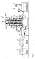
- the extrusion line 1 shown comprises an extruder 1 with a tube head 2 and a feed hopper 3. About the hopper 3 are supplied to the extruder 1 by means of a metering device, not shown polyethylene in granular or powder form, a stabilizer and peroxide. This mixture is heated in the extruder 1, kneaded and plasticized. Subsequently, the thus formed, moldable material is forced through an annular passage gap of the pipe head 2. After leaving the tube head 2, the hot, still deformable tube 4 enters a curing oven 5.
- the horizontally extruded tube 4 is first deflected at the inlet of the cross-linking furnace 5 on a roller 6 by 90 degrees, so that it passes through the cross-linking furnace 5 over a first heating distance A vertically upwards.
- a driven larger deflection roller 7 is arranged, on which the tube 4 is deflected by 180 degrees and then ⁇ end the crosslinking furnace 5 in a second heating section B passes vertically downwards.
- the heating sections A and B each have four successive infrared radiation modules 8, via which the heat required for crosslinking is introduced into the tube 4.
- the tube 4 At the outlet of the cross-linking furnace 5, the tube 4 is deflected on a further roller 9 by 90 degrees in the horizontal. After leaving the cross-linking furnace 5, the tube 4 enters a calibration and cooling unit 10, where it is cooled.
- the calibration and cooling unit 10 is followed in the extrusion line by a drawing unit 11, with which the extruded tube 4 is drawn through the extrusion line.
- the completion of the extrusion line forms a saw unit 12, are cut to the pipe sections of desired length of the extruded pipe 4.
- the extruded tube 4 (melt tube) swells after exiting the tube head 2, so that an extension of the tube 4 in the curing oven 5 is required in order to produce the desired nominal tube diameter in the tolerances to be complied can.
- four four measuring points 25 symbolically represented by circles are provided in or on the cross-linking oven 5, eg. Example in the form of laser sensors, with which the diameter D0 before the first heating distance A and the diameter D1 after the first heating distance A, and the diameter D2 before the second heating distance B and the diameter D3 after the second heating distance B are determined.
- a line speed deviating from the deflection roller 7 can be set. If the withdrawal speed were greater than the speed of the deflection roller 7, the tube 4 would be stretched in the second heating distance B. But this is to be avoided since this stretching would have a negative impact on the shrinkage to be maintained.
- the speed of the extraction unit 11 is therefore adjusted by a follow-up control of the predetermined by the guide roller 7 oven speed, d. that is, when the furnace speed is changed, the take-off speed follows in the fixed ratio of the furnace speed. This follow-up control is superimposed by a second regulation with which the speed of the drawing-off unit 11 is reduced to such an extent that the stretching S2 approaches 0 and thus the expected shrinkage is minimized.
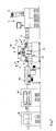
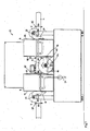
- FIG. 3 shows an enlarged view of this cross-linking furnace 13 in its starting position, while the cross-linking furnace 13 in FIG. 2 is shown in his working position.
- Such a cross-linking furnace 13 is used when larger diameter pipes 4, z. B. over 32 mm, to be produced because a deflection of such pipes by 180 degrees, as in the cross-linking furnace. 5 of the previous embodiment, is difficult to realize in practice.
- crosslinking furnace 13 will be described in more detail below, wherein the same reference numerals of the previous embodiment are taken over for the same or equivalent components.
- the cross-linking furnace 13 has a roller 6 at the inlet and a roller 9 at the outlet and a larger and driven deflection roller 7 arranged between these two rollers 6 and 9. Between the rollers 6 and 7 or 7 and 9, an infrared radiation module 8 is arranged in each case. wherein the infrared radiation module 8 arranged between the rollers 6 and 7 forms the first heating path A and the infrared radiation module 8 arranged between the rollers 7 and 9 forms the second heating path B.
- the diameters D0, D1, D2 and D3 are detected before and after the first heating distance A and the second heating distance B, respectively.
- the deflection roller 7 forms with bearing blocks 14 arranged on both sides a rotation axis 15.
- the two bearing blocks 14 are on a lifting cylinder 16 ( Fig. 2 ) arranged.
- two support arms 16 are pivotally mounted, which are connected at their ends remote from the axis of rotation 15 rigidly connected to a respective associated housing wall 17 and 18 of the infrared radiation modules 8.
- the opposite housing walls 19 and 20 of the infrared radiation modules 8 are also rigidly connected to two other support arms 21, whose other ends are pivotally mounted on the axes of rotation 22 and 23 of the rollers 6 and 9 respectively.
- FIG. 3 shows the starting position of the cross-linking furnace 13, in which the coming of the extruder 1 tube 4 is guided horizontally through the cross-linking furnace 13.
- the curing oven 13 has to be removed from its in FIG. 3 shown starting position in a in FIG. 2 shown working position.
- the lifting cylinder 16 must be extended, which is achieved by operating a hand lever 24.
- the guide roller 7 moves thereby in an elevated position and takes the infrared radiation modules 8 via the support arms 16, whereby the infrared radiation modules 8 positively controlled by the pivoting support arms 16 and 21 are synchronously adjusted in angle with the height adjustment of the guide roller 7, so that they are adjusted by the height adjustment adjust the deflection roller 7 resulting inclination of the tube 4.
Landscapes
- Engineering & Computer Science (AREA)
- Mechanical Engineering (AREA)
- Physics & Mathematics (AREA)
- Thermal Sciences (AREA)
- Health & Medical Sciences (AREA)
- Toxicology (AREA)
- Oral & Maxillofacial Surgery (AREA)
- Extrusion Moulding Of Plastics Or The Like (AREA)
- Heating, Cooling, Or Curing Plastics Or The Like In General (AREA)
- Shaping By String And By Release Of Stress In Plastics And The Like (AREA)
Abstract
Description
- Die vorliegende Erfindung betrifft ein Verfahren zur Herstellung von peroxidvernetzten Polyethylenrohren in einer Extrusionslinie gemäß dem Oberbegriff des Anspruchs 1 sowie eine Extrusionslinie mit einem Vernetzungsofen gemäß dem Oberbegriff des Anspruchs 6.
- Es ist bekannt, dass die Eigenschaften von Polymerisaten durch Vernetzung verbessert werden können. Peroxidvernetzte Polyethylenrohre haben gegenüber unvernetzten Rohren eine erhöhte Warmfestigkeit, eine verbesserte mechanische Festigkeit und eine erhöhte Chemikalienfestigkeit, was sie für Fußbodenheizungsrohre, Warmwasserrohre, Trinkwasserrohre etc. geeignet macht.
- In der
DE 696 22 053 T2 ist unter anderem eine Extrusionslinie zur Inline-Vernetzung von Polyethylenrohren beschrieben. Der Extruder dieser Linie hat einen nach oben abgewinkelten Kopf, der in einem Vernetzungsofen mündet, in den das Rohr dem zur Folge vertikal hineinextrudiert wird. Das Rohr wird im Vernetzungsofen in einer ersten Erwärmungsstrecke senkrecht nach oben geführt, dort auf einer angetriebenen Umlenkrolle um 180 Grad umgelenkt und läuft dann in einer zweiten Erwärmungsstrecke senkrecht nach unten, wo es am Auslauf des Vernetzungsofens durch eine weitere Rolle in die Horizontale umgelenkt wird und anschließend in eine Kalibrier- und Kühlstation einläuft. Auf dem Weg durch den Vernetzungsofen wird das Rohr an Infrarotstrahlern vorbeigeführt, die die für eine Vernetzung erforderliche Wärme in das Rohr einbringen. An die Kalibrier- und Kühlstation schließt sich ein Abzug an, mit dem das Rohr durch die Extrusionslinie gezogen wird, um abschließend, dem Abzug folgend, auf eine Trommel aufgewickelt zu werden. - In der
DE 10 2007 050 939 A1 ist ein Vernetzungsofen beschrieben, der eine erste Erwärmungsstrecke von seinem Einlauf bis zu einer angetriebenen Umlenkrolle und eine zweite Erwärmungsstrecke von seiner Umlenkrolle bis zu seinem Auslauf aufweist. Dabei wird ein horizontal extrudiertes Rohr am Einlauf des Vernetzungsofens zunächst auf einer Rolle um 90° umgelenkt, so dass es den Vernetzungsofen über die erste Erwärmungsstrecke vertikal nach oben durchläuft, dort an der Umlenkrolle um 180° umgelenkt wird und anschließend den Vernetzungsofen in der zweiten Erwärmungsstrecke vertikal nach unten durchläuft. An einer am Auslauf des Vernetzungsofens vorgesehenen Umlenkrolle wird das Rohr wieder in die Horizontale umgelenkt. - Der extrudierte Schmelzeschlauchs quillt nach seinem Austritt aus dem Rohrkopf des Extruders auf. Um ein Rohr mit einem geforderten Nenndurchmesser produzieren zu können, muss das Rohr daher nachfolgend in der Extrusionslinie gestreckt werden. Diese Streckung hat allerdings nachteilige Folgen für den Schrumpf, der ein wesentliches Qualitätsmerkmal des Endproduktes ist. Dieser Schrumpf muss möglichst minimal sein.
- Aufgabe der vorliegenden Erfindung ist es daher, ein Verfahren und eine Extrusionslinie mit einem Vernetzungsofen zur Verfügung zu stellen, welche einen minimalen Schrumpf des produzierten Rohres gewährleisten.
- Diese Aufgabe wird erfindungsgemäß mit einem Verfahren gelöst, welches die Merkmale des Anspruchs 1 aufweist bzw. mit einer Extrusionslinie mit den Merkmalen des Anspruchs 6.
- Die erfindungsgemäße Lösung beruht auf der Erkenntnis, dass eine Streckung des Rohres in der ersten Erwärmungsstrecke einen geringeren Einfluss auf den Schrumpf des Endproduktes hat als die Streckung in der zweiten Erwärmungsstrecke. Erfindungsgemäß werden daher die Streckung in der ersten Erwärmungsstrecke und die Streckung in der zweiten Erwärmungsstrecke überwacht und so geregelt, dass die erforderliche Streckung des Rohres überwiegend in der ersten Erwärmungsstrecke erfolgt und die Streckung des Rohres in der zweiten Erwärmungsstrecke gegen Null geregelt wird.
- Vorteilhafte Ausgestaltungen des erfindungsgemäßen Verfahrens ergeben sich aus den Unteransprüchen.
- Die vorliegende Erfindung betrifft weiterhin eine Extrusionslinie mit einem Vernetzungsofen, der eine erste Erwärmungsstrecke von seinem Einlauf bis zu einer angetriebenen Umlenkrolle und eine zweite Erwärmungsstrecke von der Umlenkrolle bis zu seinem Auslauf aufweist, wobei die Umlenkrolle höhenverstellbar ist und die Erwärmungsstrecken aus der Horizontalen winkelverstellbar sind.
- Ein derartiger Vernetzungsofen kommt bei Rohren mit größeren Durchmessern zum Einsatz, bei denen eine Umlenkung um 180 Grad auf der Umlenkrolle, wie bei den bekannten Vernetzungsöfen üblich, nur schwer zu realisieren ist. Durch die Höhenverstellbarkeit der Umlenkrolle und der Möglichkeit der Winkelverstellung der Erwärmungsstrecken kann auch bei Rohren mit größerem Durchmesser die Streckung in der ersten Erwärmungsstrecke optimal beeinflusst werden, in dem der Anpressdruck zwischen der Umlenkrolle und dem extrudierten Rohr optimal eingestellt werden kann.
- Der Vernetzungsofen kann aber auch bei Rohren kleineren Durchmessers zum Einsatz kommen, wobei die Verstellbarkeit der Umlenkrolle und der Erwärmungsstrecken neben der Antriebsgeschwindigkeit der Umlenkrolle und der Geschwindigkeit des Abzugs eine weitere Möglichkeit der Beeinflussung der Streckung des extrudierten Rohres bietet.
- Die Erfindung wird nachstehend anhand von Ausführungsbeispielen näher erläutert. In der dazu gehörigen Zeichnung zeigt:
- Fig. 1
- eine schematische Darstellung einer Extrusionslinie zur Herstellung von peroxidvernetzten Polyethylenrohren in einer ersten Ausführungsform,
- Fig. 2
- eine schematische Darstellung einer Extrusionslinie zur Herstellung von peroxidvernetzten Polyethylenrohren in einer zweiten Ausführungsform, und
- Fig. 3
- eine vergrößerte Darstellung des in der Extrusionslinie gemäß
Fig. 2 eingesetzten Vernetzungsofens in Anfahrstellung. - Die in
Figur 1 gezeigte Extrusionslinie umfasst einen Extruder 1 mit einem Rohrkopf 2 und einem Aufgabetrichter 3. Über den Aufgabetrichter 3 werden dem Extruder 1 mittels einer nicht dargestellten Dosiereinrichtung Polyethylen in Granulat- oder Pulverform, ein Stabilisator sowie Peroxid zugeführt. Diese Mischung wird im Extruder 1 erwärmt, geknetet und plastifiziert. Anschließend wird die dadurch gebildete, formbare Masse durch einen ringförmigen Durchtrittsspalt des Rohrkopfes 2 gedrückt. Nach dem Austritt aus dem Rohrkopf 2 läuft das heiße, noch verformbare Rohr 4 in einen Vernetzungsofen 5 ein. Das horizontal extrudierte Rohr 4 wird am Einlauf des Vernetzungsofens 5 zunächst auf einer Rolle 6 um 90 Grad umgelenkt, so dass es den Vernetzungsofen 5 über eine erste Erwärmungsstrecke A vertikal nach oben durchläuft. Dort ist eine angetriebene größere Umlenkrolle 7 angeordnet, auf der das Rohr 4 um 180 Grad umgelenkt wird und anschlie-βend den Vernetzungsofen 5 in einer zweiten Erwärmungsstrecke B vertikal nach unten durchläuft. - Die Erwärmungsstrecken A und B weisen jeweils vier aufeinander folgende Infrarotstrahlungsmodule 8 auf, über die die für eine Vernetzung erforderliche Wärme in das Rohr 4 eingebracht wird.
- Am Auslauf des Vernetzungsofens 5 wird das Rohr 4 auf einer weiteren Rolle 9 um 90 Grad in die Horizontale umgelenkt. Nach dem Verlassen des Vernetzungsofens 5 läuft das Rohr 4 in eine Kalibrier- und Kühleinheit 10 ein, in der es abgekühlt wird. Der Kalibrier- und Kühleinheit 10 schließt sich in der Extrusionslinie eine Abzugseinheit 11 an, mit der das extrudierte Rohr 4 durch die Extrusionslinie gezogen wird. Den Abschluss der Extrusionslinie bildet eine Sägeeinheit 12, mit der Rohrabschnitte gewünschter Länge vom extrudierten Rohr 4 abgelängt werden.
- Das extrudierte Rohr 4 (Schmelzeschlauch) quillt nach dem Austritt aus dem Rohrkopf 2 auf, so dass eine Streckung des Rohres 4 im Vernetzungsofen 5 erforderlich ist, um den gewünschten Rohrnenndurchmesser in den einzuhaltenden Toleranzgrenzen produzieren zu können. Zur Erfassung dieser Streckung sind im bzw. am Vernetzungsofen 5 vier symbolisch durch Kreise dargestellte Messstellen 25 vorgesehen, z. B. in Form von Lasersensoren, mit denen der Durchmesser D0 vor der ersten Erwärmungsstrecke A und der Durchmesser D1 nach der ersten Erwärmungsstrecke A, sowie der Durchmesser D2 vor der zweiten Erwärmungsstrecke B und der Durchmesser D3 nach der zweiten Erwärmungsstrecke B ermittelt werden. Die Streckung des Rohres 4 in der ersten Erwärmungsstrecke A ergibt sich dann aus dem Verhältnis S1 = DO/D1 und die Streckung in der zweiten Erwärmungsstrecke B aus dem Verhältnis S2 = D2/D3.
- Das Rohr 4, das durch den Vernetzungsofen 5 geführt wird, wird mittels der oberen Umlenkrolle 7 durch den Vernetzungsofen 5 gezogen. Dabei wird die Geschwindigkeit, d. h. die Drehzahl der Umlenkrolle 7 in Abhängigkeit vom Massedurchsatz am Rohrkopf 2 so geregelt, dass die für den zu produzierenden Rohrnenndurchmesser erforderliche Streckung überwiegend in der ersten Erwärmungsstrecke A realisiert wird.
- Durch die in der Extrusionslinie befindliche Abzugseinheit 11 kann eine von der Umlenkrolle 7 abweichende Liniengeschwindigkeit eingestellt werden. Wäre die Abzugsgeschwindigkeit größer als die Geschwindigkeit der Umlenkrolle 7, würde das Rohr 4 in der zweiten Erwärmungsstrecke B gestreckt werden. Das ist aber zu vermeiden, da diese Streckung einen negativen Einfluss auf den einzuhaltenden Schrumpf hätte. Die Geschwindigkeit der Abzugseinheit 11 wird daher durch eine Folgeregelung der durch die Umlenkrolle 7 vorgegebenen Ofengeschwindigkeit angepasst, d. h., wenn die Ofengeschwindigkeit geändert wird, folgt die Abzugsgeschwindigkeit im festen Verhältnis der Ofengeschwindigkeit. Diese Folgeregelung wird durch eine zweite Regelung überlagert, mit der die Geschwindigkeit der Abzugseinheit 11 soweit reduziert wird, dass die Streckung S2 gegen 0 geht und damit der zu erwartende Schrumpf minimiert wird.
- In die
Figuren 2 und3 ist ein weiteres Ausführungsbeispiel der vorliegenden Erfindung dargestellt. Es unterscheidet sich von dem vorhergehenden Ausführungsbeispiel lediglich dadurch, dass ein anderer Vernetzungsofen 13 in der Extrusionslinie eingesetzt wird.Figur 3 zeigt eine vergrößerte Darstellung dieses Vernetzungsofens 13 in seiner Anfahrstellung, während der Vernetzungsofen 13 inFigur 2 in seiner Arbeitsstellung dargestellt ist. - Ein derartiger Vernetzungsofen 13 kommt zum Einsatz, wenn Rohre 4 größeren Durchmessers, z. B. über 32 mm, produziert werden sollen, da eine Umlenkung derartiger Rohre um 180 Grad, wie in dem Vernetzungsofen 5 des vorhergehenden Ausführungsbeispiels, in der Praxis schwer zu realisieren ist.
- Der Vernetzungsofen 13 wird nachstehend näher beschrieben, wobei für gleiche oder gleich wirkende Bauteile die Bezugszeichen des vorher gehenden Ausführungsbeispiels übernommen werden.
- Der Vernetzungsofen 13 besitzt eine Rolle 6 am Einlauf und eine Rolle 9 am Auslauf sowie eine zwischen diesen beiden Rollen 6 und 9 angeordnete, größere und angetriebene Umlenkrolle 7. Zwischen den Rollen 6 und 7 bzw. 7 und 9 ist jeweils ein Infrarotstrahlungsmodul 8 angeordnet, wobei das zwischen den Rollen 6 und 7 angeordnete Infrarotstrahlungsmodul 8 die erste Erwärmungsstrecke A und das zwischen den Rollen 7 und 9 angeordnete Infrarotstrahlungsmodul 8 die zweite Erwärmungsstrecke B bildet.
- Auch bei diesem Ausführungsbeispiel werden die Durchmesser D0, D1, D2 und D3 vor und nach der ersten Erwärmungsstrecke A bzw. der zweiten Erwärmungsstrecke B erfasst.
- Die Umlenkrolle 7 bildet mit beidseitig angeordneten Lagerböcken 14 eine Drehachse 15 aus. Die beiden Lagerböcke 14 sind auf einem Hubzylinder 16 (
Fig. 2 ) angeordnet. - Auf der Drehachse 15 der Umlenkrolle 7 sind zwei Tragarme 16 schwenkbar gelagert, die an ihren der Drehachse 15 abgewandten Enden starr mit einer jeweils zugeordneten Gehäusewand 17 bzw. 18 der Infrarotstrahlungsmodule 8 verbunden sind. Die gegenüberliegenden Gehäusewände 19 bzw. 20 der Infrarotstrahlungsmodule 8 sind ebenfalls starr mit zwei weiteren Tragarmen 21 verbundenen, deren anderen Enden schwenkbar auf den Drehachsen 22 und 23 der Rollen 6 bzw. 9 gelagert sind.
-
Figur 3 zeigt die Anfahrstellung des Vernetzungsofens 13, bei der das vom Extruder 1 kommende Rohr 4 horizontal durch den Vernetzungsofen 13 geführt ist. - Um die Streckung S1 und S2 gemäß dem vorhergehenden Ausführungsbeispiel regeln zu können, muss der Vernetzungsofen 13 aus seiner in
Figur 3 gezeigten Anfahrstellung in eine inFigur 2 gezeigte Arbeitsstellung überführt werden. Dazu muss der Hubzylinder 16 ausgefahren werden, was durch Betätigung eines Handhebels 24 erreicht wird. Die Umlenkrolle 7 fährt dadurch in eine erhöhte Position und nimmt die Infrarotstrahlungsmodule 8 über die Tragarme 16 mit, wodurch die Infrarotbestrahlungsmodule 8 zwangsgesteuert durch die verschwenkenden Tragarme 16 und 21 synchron mit der Höhenverstellung der Umlenkrolle 7 winkelverstellt werden, so dass sie sich der durch die Höhenverstellung der Umlenkrolle 7 ergebenden Neigung des Rohres 4 anpassen. - Die Steuerung der Extrusionslinie hinsichtlich der Streckungen S1 und S2 des extrudierten Rohres 4 erfolgt wie bei dem vorhergehenden Ausführungsbeispiel.
Claims (7)
- Verfahren zur Herstellung von peroxidvernetzten Polyethylenrohren in einer Extrusionslinie mit einem Extruder, einem Vernetzungsofen und einem Abzug, wobei das extrudierte Rohr einer Streckung unterzogen wird, und der Vernetzungsofen eine erste Erwärmungsstrecke von seinem Einlauf bis zu einer angetriebenen Umlenkrolle und eine zweite Erwärmungsstrecke von der Umlenkrolle bis zu seinem Auslauf aufweist, dadurch gekennzeichnet, dass die Streckung (S1) in der ersten Erwärmungsstrecke (A) und die Streckung (S2) in der zweiten Erwärmungsstrecke (B) überwacht und so geregelt wird, dass die erforderliche Streckung des Rohres (4) überwiegend in der ersten Erwärmungsstrecke (A) erfolgt und die Streckung (S2) des Rohres (4) in der zweiten Erwärmungsstrecke (B) gegen 0 geregelt wird.
- Verfahren nach Anspruch 1, dadurch gekennzeichnet, dass zur Überwachung der Streckung (S1) in der ersten Erwärmungsstrecke (A) der Rohrdurchmesser (D0) vor der ersten Erwärmungsstrecke (A) und der Rohrdurchmesser (D1) nach der ersten Erwärmungsstrecke (A) und zur Überwachung der Streckung S2 in der zweiten Erwärmungsstrecke (B) der Rohrdurchmesser (D2) vor der zweiten Erwärmungsstrecke (B) und der Rohrdurchmesser (D3) nach der zweiten Erwärmungsstrecke (B) erfasst werden.
- Verfahren nach Anspruch 1 oder Anspruch 2, dadurch gekennzeichnet, dass die Umdrehungsgeschwindigkeit der Umlenkrolle (7) so geregelt wird, dass eine optimale Streckung (S1) in der ersten Erwärmungsstrecke (A) erfolgt.
- Verfahren nach Anspruch 3, dadurch gekennzeichnet, dass eine Folgeregelung der Geschwindigkeit der Abzugseinheit (11) im festen Verhältnis zur Umdrehungsgeschwindigkeit der Umlenkrolle (7) erfolgt.
- Verfahren nach Anspruch 4, dadurch gekennzeichnet, dass der Folgeregelung der Abzugseinheit (11) eine zweite Regelung überlagert wird, wodurch die Geschwindigkeit der Abzugseinheit (11) soweit reduziert wird, dass die Streckung (S2) in der zweiten Erwärmungsstrecke (B) gegen 0 geht.
- Extrusionslinie mit einem Vernetzungsofen, der eine erste Erwärmungsstrecke von seinem Einlauf bis zu einer angetriebenen Umlenkrolle und eine zweite Erwärmungsstrecke von seiner Umlenkrolle bis zu seinem Auslauf aufweist, dadurch gekennzeichnet, dass die Umlenkrolle (7) höhenverstellbar ist, und die Erwärmungsstrecken (A, B) aus der Horizontalen winkelverstellbar sind.
- Extrusionslinie nach Anspruch 6, dadurch gekennzeichnet, dass die Winkelverstellung an die Höhenverstellung gekoppelt ist.
Priority Applications (1)
| Application Number | Priority Date | Filing Date | Title |
|---|---|---|---|
| EP16201146.4A EP3170642A1 (de) | 2010-01-23 | 2010-12-15 | Verfahren zur herstellung von peroxidvernetzten polyethylenrohren in einer extrusionslinie |
Applications Claiming Priority (1)
| Application Number | Priority Date | Filing Date | Title |
|---|---|---|---|
| DE102010005509A DE102010005509B4 (de) | 2010-01-23 | 2010-01-23 | Verfahren zur Herstellung von peroxidvernetzten Polyethylenrohren in einer Extrusionslinie |
Related Child Applications (2)
| Application Number | Title | Priority Date | Filing Date |
|---|---|---|---|
| EP16201146.4A Division-Into EP3170642A1 (de) | 2010-01-23 | 2010-12-15 | Verfahren zur herstellung von peroxidvernetzten polyethylenrohren in einer extrusionslinie |
| EP16201146.4A Division EP3170642A1 (de) | 2010-01-23 | 2010-12-15 | Verfahren zur herstellung von peroxidvernetzten polyethylenrohren in einer extrusionslinie |
Publications (3)
| Publication Number | Publication Date |
|---|---|
| EP2347878A2 true EP2347878A2 (de) | 2011-07-27 |
| EP2347878A3 EP2347878A3 (de) | 2016-08-10 |
| EP2347878B1 EP2347878B1 (de) | 2018-12-26 |
Family
ID=43875352
Family Applications (2)
| Application Number | Title | Priority Date | Filing Date |
|---|---|---|---|
| EP10015646.2A Active EP2347878B1 (de) | 2010-01-23 | 2010-12-15 | Verfahren zur herstellung von peroxidvernetzten polyethylenrohren in einer extrusionslinie |
| EP16201146.4A Withdrawn EP3170642A1 (de) | 2010-01-23 | 2010-12-15 | Verfahren zur herstellung von peroxidvernetzten polyethylenrohren in einer extrusionslinie |
Family Applications After (1)
| Application Number | Title | Priority Date | Filing Date |
|---|---|---|---|
| EP16201146.4A Withdrawn EP3170642A1 (de) | 2010-01-23 | 2010-12-15 | Verfahren zur herstellung von peroxidvernetzten polyethylenrohren in einer extrusionslinie |
Country Status (5)
| Country | Link |
|---|---|
| US (2) | US8641947B2 (de) |
| EP (2) | EP2347878B1 (de) |
| CN (1) | CN102139538B (de) |
| DE (1) | DE102010005509B4 (de) |
| ES (1) | ES2715607T3 (de) |
Cited By (2)
| Publication number | Priority date | Publication date | Assignee | Title |
|---|---|---|---|---|
| CN105156853A (zh) * | 2015-08-17 | 2015-12-16 | 苏州科润织造有限公司 | 一种纺织机架 |
| EP3613554A1 (de) * | 2018-08-21 | 2020-02-26 | Crosslink Finland Oy | Verfahren und system zur herstellung eines polymerrohrs |
Families Citing this family (8)
| Publication number | Priority date | Publication date | Assignee | Title |
|---|---|---|---|---|
| CN102642290B (zh) * | 2012-04-28 | 2014-07-16 | 东莞日进电线有限公司 | 一种穿线硅胶套管的制备工艺 |
| US10640403B2 (en) | 2013-08-15 | 2020-05-05 | Applied Silver, Inc. | Antimicrobial batch dilution system |
| US11618696B2 (en) | 2013-08-15 | 2023-04-04 | Applied Silver, Inc. | Antimicrobial batch dilution system |
| US9689106B2 (en) | 2013-12-06 | 2017-06-27 | Applied Silver, Inc. | Antimicrobial fabric application system |
| US20170050870A1 (en) | 2015-08-21 | 2017-02-23 | Applied Silver, Inc. | Systems And Processes For Treating Textiles With An Antimicrobial Agent |
| US10760207B2 (en) | 2017-03-01 | 2020-09-01 | Applied Silver, Inc. | Systems and processes for treating textiles with an antimicrobial agent |
| CN109352942B (zh) * | 2018-11-29 | 2024-02-06 | 浙江曼瑞德舒适系统有限公司 | 一种用于过氧化物交联聚乙烯管材制备的浮床交联炉 |
| CN120347973B (zh) * | 2025-06-23 | 2025-09-30 | 日丰企业(佛山)有限公司 | 制造过氧化物交联聚乙烯管的系统及其交联炉 |
Citations (2)
| Publication number | Priority date | Publication date | Assignee | Title |
|---|---|---|---|---|
| DE69622053T2 (de) | 1995-09-20 | 2002-11-14 | Uponor Wirsbo Ab, Virsbo | Verfahren zum heizen und/oder vernetzen von polymeren und dazugehörende vorrichtung |
| DE102007050939A1 (de) | 2007-10-23 | 2009-04-30 | Inoex Gmbh | Verfahren zum Erwärmen eines extrudierten Kunststoffprofils durch Infrarotstrahlung |
Family Cites Families (3)
| Publication number | Priority date | Publication date | Assignee | Title |
|---|---|---|---|---|
| US6506333B1 (en) * | 1996-05-03 | 2003-01-14 | Baxter International Inc. | Method of surface modifying a medical tubing |
| DE102005062138A1 (de) * | 2005-12-22 | 2007-07-05 | Inoex Gmbh | Kalibrierhülse für extrudierte Kunststoffrohre |
| US9067367B2 (en) * | 2012-03-02 | 2015-06-30 | Pexcor Manufacturing Company, Inc. | Method and system for performing an infrared treatment |
-
2010
- 2010-01-23 DE DE102010005509A patent/DE102010005509B4/de active Active
- 2010-12-15 EP EP10015646.2A patent/EP2347878B1/de active Active
- 2010-12-15 EP EP16201146.4A patent/EP3170642A1/de not_active Withdrawn
- 2010-12-15 ES ES10015646T patent/ES2715607T3/es active Active
-
2011
- 2011-01-21 CN CN201110056129.0A patent/CN102139538B/zh active Active
- 2011-01-24 US US13/012,685 patent/US8641947B2/en active Active
-
2013
- 2013-12-26 US US14/140,936 patent/US9039403B2/en active Active
Patent Citations (2)
| Publication number | Priority date | Publication date | Assignee | Title |
|---|---|---|---|---|
| DE69622053T2 (de) | 1995-09-20 | 2002-11-14 | Uponor Wirsbo Ab, Virsbo | Verfahren zum heizen und/oder vernetzen von polymeren und dazugehörende vorrichtung |
| DE102007050939A1 (de) | 2007-10-23 | 2009-04-30 | Inoex Gmbh | Verfahren zum Erwärmen eines extrudierten Kunststoffprofils durch Infrarotstrahlung |
Cited By (2)
| Publication number | Priority date | Publication date | Assignee | Title |
|---|---|---|---|---|
| CN105156853A (zh) * | 2015-08-17 | 2015-12-16 | 苏州科润织造有限公司 | 一种纺织机架 |
| EP3613554A1 (de) * | 2018-08-21 | 2020-02-26 | Crosslink Finland Oy | Verfahren und system zur herstellung eines polymerrohrs |
Also Published As
| Publication number | Publication date |
|---|---|
| US9039403B2 (en) | 2015-05-26 |
| CN102139538A (zh) | 2011-08-03 |
| EP2347878A3 (de) | 2016-08-10 |
| US20140106017A1 (en) | 2014-04-17 |
| ES2715607T3 (es) | 2019-06-05 |
| EP2347878B1 (de) | 2018-12-26 |
| DE102010005509A1 (de) | 2011-07-28 |
| EP3170642A1 (de) | 2017-05-24 |
| US20110180954A1 (en) | 2011-07-28 |
| DE102010005509B4 (de) | 2011-11-10 |
| CN102139538B (zh) | 2015-07-01 |
| US8641947B2 (en) | 2014-02-04 |
Similar Documents
| Publication | Publication Date | Title |
|---|---|---|
| EP2347878B1 (de) | Verfahren zur herstellung von peroxidvernetzten polyethylenrohren in einer extrusionslinie | |
| DE102011018320B4 (de) | Verfahren und Vorrichtung zur Dickenprofilregelung | |
| EP3022040B2 (de) | Vorrichtung zur herstellung von inline gereckten folien | |
| EP2991816B1 (de) | Verfahren zur regelung des dickenprofils von inline gereckten folien | |
| EP2404735B1 (de) | Verfahren und Vorrichtung zum Anfahren einer Rohrextrusionslinie | |
| DE102016119872A1 (de) | Verfahren und Vorrichtung zur Regelung der Formstabilität eines Folienschlauchs bei dessen Herstellung mittels einer Blasfolienextrusionsanlage | |
| DE102015006891A1 (de) | Anlage zum Herstellen einer Folienbahn sowie Verfahren zum Betreiben einer solchen Anlage | |
| EP4442427A1 (de) | Folienblasanlage und verfahren zum regeln einer folienblasanlage | |
| DE2758266C2 (de) | Einrichtung zur Regelung des Durchsatzes eines an einem Polymerisationssystem angeschlossenen Ein- oder Doppelschneckenextruder | |
| WO2017198262A1 (de) | Verfahren und anordnung zur regelung und steuerung von rohrextrusionsanlagen | |
| EP2783028A1 (de) | Vorrichtung zur herstellung eines spinnkabels | |
| DE102019107335B4 (de) | Vorrichtung und verfahren zur herstellung einer folienbahn | |
| EP2384879A1 (de) | Verfahren und Vorrichtung zum Umformen von Metallen und Kunststoffen, sowie rohr- oder schlauchförmiges Produkt | |
| DE202023101698U1 (de) | Folienblasanlage | |
| DE202013012786U1 (de) | Vorrichtung zur Herstellung von inline gereckten Folien | |
| EP1800833A1 (de) | Kalibrierhülse für extrudierte Kunststoffrohre | |
| DE102006049660B3 (de) | Vorrichtung zum Extrudieren von Hohlsträngen | |
| WO2010029142A2 (de) | Vorrichtung und verfahren zum kühlen von kunststoffprofilen | |
| DE102007026751A1 (de) | Verfahren zur Herstellung von peroxidvernetzten Polyethylen-Rohren in einer Extrusionslinie | |
| DE102020131010A1 (de) | Blasfolienanlage und verfahren zum herstellen einer blasfolienbahn | |
| EP1627724A2 (de) | Verfahren und Vorrichtung zur Herstellung von Kunststoffrohren in einer Extrusionslinie | |
| EP3088159B1 (de) | Kühlring und verfahren zur aussenkühlung einer schlauchfolie aus thermoplastischem kunststoff bei deren herstellung | |
| EP0594018A1 (de) | Vorrichtung zum Extrudieren von Kunststoffprofilen | |
| EP1985433B1 (de) | Verfahren zur Herstellung von rohrförmigen Kunststoffprofilen | |
| DE102013022651B4 (de) | Vorrichtung zur Herstellung von inline gereckten Folien |
Legal Events
| Date | Code | Title | Description |
|---|---|---|---|
| PUAI | Public reference made under article 153(3) epc to a published international application that has entered the european phase |
Free format text: ORIGINAL CODE: 0009012 |
|
| AK | Designated contracting states |
Kind code of ref document: A2 Designated state(s): AL AT BE BG CH CY CZ DE DK EE ES FI FR GB GR HR HU IE IS IT LI LT LU LV MC MK MT NL NO PL PT RO RS SE SI SK SM TR |
|
| AX | Request for extension of the european patent |
Extension state: BA ME |
|
| RIC1 | Information provided on ipc code assigned before grant |
Ipc: B29C 47/00 20060101ALN20160324BHEP Ipc: B29C 35/08 20060101ALN20160324BHEP Ipc: B29C 47/92 20060101ALN20160324BHEP Ipc: B29C 35/10 20060101ALN20160324BHEP Ipc: B29K 105/24 20060101ALN20160324BHEP Ipc: B29C 55/22 20060101ALI20160324BHEP Ipc: B29C 47/90 20060101ALN20160324BHEP Ipc: B29L 23/00 20060101ALN20160324BHEP Ipc: B29K 105/10 20060101ALN20160324BHEP Ipc: B29C 47/88 20060101ALN20160324BHEP Ipc: B29C 35/06 20060101AFI20160324BHEP |
|
| PUAL | Search report despatched |
Free format text: ORIGINAL CODE: 0009013 |
|
| AK | Designated contracting states |
Kind code of ref document: A3 Designated state(s): AL AT BE BG CH CY CZ DE DK EE ES FI FR GB GR HR HU IE IS IT LI LT LU LV MC MK MT NL NO PL PT RO RS SE SI SK SM TR |
|
| AX | Request for extension of the european patent |
Extension state: BA ME |
|
| RIC1 | Information provided on ipc code assigned before grant |
Ipc: B29L 23/00 20060101ALN20160704BHEP Ipc: B29C 55/22 20060101ALI20160704BHEP Ipc: B29C 47/92 20060101ALN20160704BHEP Ipc: B29K 105/24 20060101ALN20160704BHEP Ipc: B29C 35/10 20060101ALN20160704BHEP Ipc: B29C 47/90 20060101ALN20160704BHEP Ipc: B29C 47/00 20060101ALN20160704BHEP Ipc: B29C 47/88 20060101ALN20160704BHEP Ipc: B29K 105/10 20060101ALN20160704BHEP Ipc: B29C 35/06 20060101AFI20160704BHEP Ipc: B29C 35/08 20060101ALN20160704BHEP |
|
| STAA | Information on the status of an ep patent application or granted ep patent |
Free format text: STATUS: REQUEST FOR EXAMINATION WAS MADE |
|
| 17P | Request for examination filed |
Effective date: 20161121 |
|
| RBV | Designated contracting states (corrected) |
Designated state(s): AL AT BE BG CH CY CZ DE DK EE ES FI FR GB GR HR HU IE IS IT LI LT LU LV MC MK MT NL NO PL PT RO RS SE SI SK SM TR |
|
| GRAP | Despatch of communication of intention to grant a patent |
Free format text: ORIGINAL CODE: EPIDOSNIGR1 |
|
| STAA | Information on the status of an ep patent application or granted ep patent |
Free format text: STATUS: GRANT OF PATENT IS INTENDED |
|
| RIC1 | Information provided on ipc code assigned before grant |
Ipc: B29C 47/88 20060101ALN20180720BHEP Ipc: B29C 55/22 20060101ALI20180720BHEP Ipc: B29C 35/08 20060101ALN20180720BHEP Ipc: B29K 105/10 20060101ALN20180720BHEP Ipc: B29C 47/92 20060101ALN20180720BHEP Ipc: B29C 35/06 20060101AFI20180720BHEP Ipc: B29C 47/00 20060101ALN20180720BHEP Ipc: B29C 35/10 20060101ALN20180720BHEP Ipc: B29C 47/90 20060101ALN20180720BHEP Ipc: B29L 23/00 20060101ALN20180720BHEP Ipc: B29K 105/24 20060101ALN20180720BHEP |
|
| RIC1 | Information provided on ipc code assigned before grant |
Ipc: B29C 35/08 20060101ALN20180814BHEP Ipc: B29C 55/22 20060101ALI20180814BHEP Ipc: B29L 23/00 20060101ALN20180814BHEP Ipc: B29C 47/88 20060101ALN20180814BHEP Ipc: B29K 105/24 20060101ALN20180814BHEP Ipc: B29C 47/00 20060101ALN20180814BHEP Ipc: B29C 47/90 20060101ALN20180814BHEP Ipc: B29C 35/10 20060101ALN20180814BHEP Ipc: B29K 105/10 20060101ALN20180814BHEP Ipc: B29C 35/06 20060101AFI20180814BHEP Ipc: B29C 47/92 20060101ALN20180814BHEP |
|
| INTG | Intention to grant announced |
Effective date: 20180829 |
|
| RIC1 | Information provided on ipc code assigned before grant |
Ipc: B29C 35/10 20060101ALN20180821BHEP Ipc: B29C 47/00 20060101ALN20180821BHEP Ipc: B29K 105/24 20060101ALN20180821BHEP Ipc: B29C 47/90 20060101ALN20180821BHEP Ipc: B29C 47/88 20060101ALN20180821BHEP Ipc: B29L 23/00 20060101ALN20180821BHEP Ipc: B29C 55/22 20060101ALI20180821BHEP Ipc: B29C 35/08 20060101ALN20180821BHEP Ipc: B29K 105/10 20060101ALN20180821BHEP Ipc: B29C 47/92 20060101ALN20180821BHEP Ipc: B29C 35/06 20060101AFI20180821BHEP |
|
| GRAS | Grant fee paid |
Free format text: ORIGINAL CODE: EPIDOSNIGR3 |
|
| GRAA | (expected) grant |
Free format text: ORIGINAL CODE: 0009210 |
|
| STAA | Information on the status of an ep patent application or granted ep patent |
Free format text: STATUS: THE PATENT HAS BEEN GRANTED |
|
| AK | Designated contracting states |
Kind code of ref document: B1 Designated state(s): AL AT BE BG CH CY CZ DE DK EE ES FI FR GB GR HR HU IE IS IT LI LT LU LV MC MK MT NL NO PL PT RO RS SE SI SK SM TR |
|
| REG | Reference to a national code |
Ref country code: GB Ref legal event code: FG4D Free format text: NOT ENGLISH |
|
| REG | Reference to a national code |
Ref country code: CH Ref legal event code: EP |
|
| REG | Reference to a national code |
Ref country code: AT Ref legal event code: REF Ref document number: 1080775 Country of ref document: AT Kind code of ref document: T Effective date: 20190115 |
|
| REG | Reference to a national code |
Ref country code: DE Ref legal event code: R096 Ref document number: 502010015653 Country of ref document: DE |
|
| REG | Reference to a national code |
Ref country code: IE Ref legal event code: FG4D Free format text: LANGUAGE OF EP DOCUMENT: GERMAN |
|
| REG | Reference to a national code |
Ref country code: SE Ref legal event code: TRGR |
|
| PG25 | Lapsed in a contracting state [announced via postgrant information from national office to epo] |
Ref country code: BG Free format text: LAPSE BECAUSE OF FAILURE TO SUBMIT A TRANSLATION OF THE DESCRIPTION OR TO PAY THE FEE WITHIN THE PRESCRIBED TIME-LIMIT Effective date: 20190326 Ref country code: HR Free format text: LAPSE BECAUSE OF FAILURE TO SUBMIT A TRANSLATION OF THE DESCRIPTION OR TO PAY THE FEE WITHIN THE PRESCRIBED TIME-LIMIT Effective date: 20181226 Ref country code: LT Free format text: LAPSE BECAUSE OF FAILURE TO SUBMIT A TRANSLATION OF THE DESCRIPTION OR TO PAY THE FEE WITHIN THE PRESCRIBED TIME-LIMIT Effective date: 20181226 Ref country code: NO Free format text: LAPSE BECAUSE OF FAILURE TO SUBMIT A TRANSLATION OF THE DESCRIPTION OR TO PAY THE FEE WITHIN THE PRESCRIBED TIME-LIMIT Effective date: 20190326 Ref country code: LV Free format text: LAPSE BECAUSE OF FAILURE TO SUBMIT A TRANSLATION OF THE DESCRIPTION OR TO PAY THE FEE WITHIN THE PRESCRIBED TIME-LIMIT Effective date: 20181226 |
|
| REG | Reference to a national code |
Ref country code: NL Ref legal event code: MP Effective date: 20181226 |
|
| REG | Reference to a national code |
Ref country code: LT Ref legal event code: MG4D |
|
| PG25 | Lapsed in a contracting state [announced via postgrant information from national office to epo] |
Ref country code: AL Free format text: LAPSE BECAUSE OF FAILURE TO SUBMIT A TRANSLATION OF THE DESCRIPTION OR TO PAY THE FEE WITHIN THE PRESCRIBED TIME-LIMIT Effective date: 20181226 Ref country code: RS Free format text: LAPSE BECAUSE OF FAILURE TO SUBMIT A TRANSLATION OF THE DESCRIPTION OR TO PAY THE FEE WITHIN THE PRESCRIBED TIME-LIMIT Effective date: 20181226 Ref country code: GR Free format text: LAPSE BECAUSE OF FAILURE TO SUBMIT A TRANSLATION OF THE DESCRIPTION OR TO PAY THE FEE WITHIN THE PRESCRIBED TIME-LIMIT Effective date: 20190327 |
|
| REG | Reference to a national code |
Ref country code: ES Ref legal event code: FG2A Ref document number: 2715607 Country of ref document: ES Kind code of ref document: T3 Effective date: 20190605 |
|
| PG25 | Lapsed in a contracting state [announced via postgrant information from national office to epo] |
Ref country code: NL Free format text: LAPSE BECAUSE OF FAILURE TO SUBMIT A TRANSLATION OF THE DESCRIPTION OR TO PAY THE FEE WITHIN THE PRESCRIBED TIME-LIMIT Effective date: 20181226 |
|
| PG25 | Lapsed in a contracting state [announced via postgrant information from national office to epo] |
Ref country code: PL Free format text: LAPSE BECAUSE OF FAILURE TO SUBMIT A TRANSLATION OF THE DESCRIPTION OR TO PAY THE FEE WITHIN THE PRESCRIBED TIME-LIMIT Effective date: 20181226 Ref country code: PT Free format text: LAPSE BECAUSE OF FAILURE TO SUBMIT A TRANSLATION OF THE DESCRIPTION OR TO PAY THE FEE WITHIN THE PRESCRIBED TIME-LIMIT Effective date: 20190426 Ref country code: CZ Free format text: LAPSE BECAUSE OF FAILURE TO SUBMIT A TRANSLATION OF THE DESCRIPTION OR TO PAY THE FEE WITHIN THE PRESCRIBED TIME-LIMIT Effective date: 20181226 |
|
| PG25 | Lapsed in a contracting state [announced via postgrant information from national office to epo] |
Ref country code: RO Free format text: LAPSE BECAUSE OF FAILURE TO SUBMIT A TRANSLATION OF THE DESCRIPTION OR TO PAY THE FEE WITHIN THE PRESCRIBED TIME-LIMIT Effective date: 20181226 Ref country code: IS Free format text: LAPSE BECAUSE OF FAILURE TO SUBMIT A TRANSLATION OF THE DESCRIPTION OR TO PAY THE FEE WITHIN THE PRESCRIBED TIME-LIMIT Effective date: 20190426 Ref country code: SK Free format text: LAPSE BECAUSE OF FAILURE TO SUBMIT A TRANSLATION OF THE DESCRIPTION OR TO PAY THE FEE WITHIN THE PRESCRIBED TIME-LIMIT Effective date: 20181226 Ref country code: SM Free format text: LAPSE BECAUSE OF FAILURE TO SUBMIT A TRANSLATION OF THE DESCRIPTION OR TO PAY THE FEE WITHIN THE PRESCRIBED TIME-LIMIT Effective date: 20181226 Ref country code: EE Free format text: LAPSE BECAUSE OF FAILURE TO SUBMIT A TRANSLATION OF THE DESCRIPTION OR TO PAY THE FEE WITHIN THE PRESCRIBED TIME-LIMIT Effective date: 20181226 |
|
| REG | Reference to a national code |
Ref country code: DE Ref legal event code: R097 Ref document number: 502010015653 Country of ref document: DE |
|
| PG25 | Lapsed in a contracting state [announced via postgrant information from national office to epo] |
Ref country code: DK Free format text: LAPSE BECAUSE OF FAILURE TO SUBMIT A TRANSLATION OF THE DESCRIPTION OR TO PAY THE FEE WITHIN THE PRESCRIBED TIME-LIMIT Effective date: 20181226 |
|
| PLBE | No opposition filed within time limit |
Free format text: ORIGINAL CODE: 0009261 |
|
| STAA | Information on the status of an ep patent application or granted ep patent |
Free format text: STATUS: NO OPPOSITION FILED WITHIN TIME LIMIT |
|
| 26N | No opposition filed |
Effective date: 20190927 |
|
| PG25 | Lapsed in a contracting state [announced via postgrant information from national office to epo] |
Ref country code: SI Free format text: LAPSE BECAUSE OF FAILURE TO SUBMIT A TRANSLATION OF THE DESCRIPTION OR TO PAY THE FEE WITHIN THE PRESCRIBED TIME-LIMIT Effective date: 20181226 |
|
| PG25 | Lapsed in a contracting state [announced via postgrant information from national office to epo] |
Ref country code: TR Free format text: LAPSE BECAUSE OF FAILURE TO SUBMIT A TRANSLATION OF THE DESCRIPTION OR TO PAY THE FEE WITHIN THE PRESCRIBED TIME-LIMIT Effective date: 20181226 |
|
| REG | Reference to a national code |
Ref country code: DE Ref legal event code: R119 Ref document number: 502010015653 Country of ref document: DE |
|
| REG | Reference to a national code |
Ref country code: CH Ref legal event code: PL |
|
| REG | Reference to a national code |
Ref country code: BE Ref legal event code: MM Effective date: 20191231 |
|
| PG25 | Lapsed in a contracting state [announced via postgrant information from national office to epo] |
Ref country code: MC Free format text: LAPSE BECAUSE OF FAILURE TO SUBMIT A TRANSLATION OF THE DESCRIPTION OR TO PAY THE FEE WITHIN THE PRESCRIBED TIME-LIMIT Effective date: 20181226 |
|
| GBPC | Gb: european patent ceased through non-payment of renewal fee |
Effective date: 20191215 |
|
| PG25 | Lapsed in a contracting state [announced via postgrant information from national office to epo] |
Ref country code: IE Free format text: LAPSE BECAUSE OF NON-PAYMENT OF DUE FEES Effective date: 20191215 Ref country code: LU Free format text: LAPSE BECAUSE OF NON-PAYMENT OF DUE FEES Effective date: 20191215 Ref country code: GB Free format text: LAPSE BECAUSE OF NON-PAYMENT OF DUE FEES Effective date: 20191215 Ref country code: FR Free format text: LAPSE BECAUSE OF NON-PAYMENT OF DUE FEES Effective date: 20191231 Ref country code: DE Free format text: LAPSE BECAUSE OF NON-PAYMENT OF DUE FEES Effective date: 20200701 |
|
| PG25 | Lapsed in a contracting state [announced via postgrant information from national office to epo] |
Ref country code: LI Free format text: LAPSE BECAUSE OF NON-PAYMENT OF DUE FEES Effective date: 20191231 Ref country code: CH Free format text: LAPSE BECAUSE OF NON-PAYMENT OF DUE FEES Effective date: 20191231 Ref country code: BE Free format text: LAPSE BECAUSE OF NON-PAYMENT OF DUE FEES Effective date: 20191231 |
|
| REG | Reference to a national code |
Ref country code: AT Ref legal event code: MM01 Ref document number: 1080775 Country of ref document: AT Kind code of ref document: T Effective date: 20191215 |
|
| PG25 | Lapsed in a contracting state [announced via postgrant information from national office to epo] |
Ref country code: CY Free format text: LAPSE BECAUSE OF FAILURE TO SUBMIT A TRANSLATION OF THE DESCRIPTION OR TO PAY THE FEE WITHIN THE PRESCRIBED TIME-LIMIT Effective date: 20181226 Ref country code: AT Free format text: LAPSE BECAUSE OF NON-PAYMENT OF DUE FEES Effective date: 20191215 |
|
| PG25 | Lapsed in a contracting state [announced via postgrant information from national office to epo] |
Ref country code: HU Free format text: LAPSE BECAUSE OF FAILURE TO SUBMIT A TRANSLATION OF THE DESCRIPTION OR TO PAY THE FEE WITHIN THE PRESCRIBED TIME-LIMIT; INVALID AB INITIO Effective date: 20101215 Ref country code: MT Free format text: LAPSE BECAUSE OF FAILURE TO SUBMIT A TRANSLATION OF THE DESCRIPTION OR TO PAY THE FEE WITHIN THE PRESCRIBED TIME-LIMIT Effective date: 20181226 |
|
| PG25 | Lapsed in a contracting state [announced via postgrant information from national office to epo] |
Ref country code: MK Free format text: LAPSE BECAUSE OF FAILURE TO SUBMIT A TRANSLATION OF THE DESCRIPTION OR TO PAY THE FEE WITHIN THE PRESCRIBED TIME-LIMIT Effective date: 20181226 |
|
| PGFP | Annual fee paid to national office [announced via postgrant information from national office to epo] |
Ref country code: FI Payment date: 20251216 Year of fee payment: 16 |
|
| PGFP | Annual fee paid to national office [announced via postgrant information from national office to epo] |
Ref country code: SE Payment date: 20251217 Year of fee payment: 16 |
|
| PGFP | Annual fee paid to national office [announced via postgrant information from national office to epo] |
Ref country code: ES Payment date: 20260119 Year of fee payment: 16 |
|
| PGFP | Annual fee paid to national office [announced via postgrant information from national office to epo] |
Ref country code: IT Payment date: 20251231 Year of fee payment: 16 |