EP2347822A1 - Diesel exhaust gas purification catalyst and diesel exhaust gas purification system - Google Patents
Diesel exhaust gas purification catalyst and diesel exhaust gas purification system Download PDFInfo
- Publication number
- EP2347822A1 EP2347822A1 EP09824862A EP09824862A EP2347822A1 EP 2347822 A1 EP2347822 A1 EP 2347822A1 EP 09824862 A EP09824862 A EP 09824862A EP 09824862 A EP09824862 A EP 09824862A EP 2347822 A1 EP2347822 A1 EP 2347822A1
- Authority
- EP
- European Patent Office
- Prior art keywords
- catalyst
- exhaust gas
- composite oxide
- gas purification
- diesel exhaust
- Prior art date
- Legal status (The legal status is an assumption and is not a legal conclusion. Google has not performed a legal analysis and makes no representation as to the accuracy of the status listed.)
- Granted
Links
Images


Classifications
-
- B—PERFORMING OPERATIONS; TRANSPORTING
- B01—PHYSICAL OR CHEMICAL PROCESSES OR APPARATUS IN GENERAL
- B01D—SEPARATION
- B01D53/00—Separation of gases or vapours; Recovering vapours of volatile solvents from gases; Chemical or biological purification of waste gases, e.g. engine exhaust gases, smoke, fumes, flue gases, aerosols
- B01D53/34—Chemical or biological purification of waste gases
- B01D53/92—Chemical or biological purification of waste gases of engine exhaust gases
- B01D53/94—Chemical or biological purification of waste gases of engine exhaust gases by catalytic processes
- B01D53/9404—Removing only nitrogen compounds
- B01D53/9409—Nitrogen oxides
- B01D53/9413—Processes characterised by a specific catalyst
- B01D53/9422—Processes characterised by a specific catalyst for removing nitrogen oxides by NOx storage or reduction by cyclic switching between lean and rich exhaust gases (LNT, NSC, NSR)
-
- B—PERFORMING OPERATIONS; TRANSPORTING
- B01—PHYSICAL OR CHEMICAL PROCESSES OR APPARATUS IN GENERAL
- B01J—CHEMICAL OR PHYSICAL PROCESSES, e.g. CATALYSIS OR COLLOID CHEMISTRY; THEIR RELEVANT APPARATUS
- B01J29/00—Catalysts comprising molecular sieves
- B01J29/04—Catalysts comprising molecular sieves having base-exchange properties, e.g. crystalline zeolites
- B01J29/06—Crystalline aluminosilicate zeolites; Isomorphous compounds thereof
- B01J29/064—Crystalline aluminosilicate zeolites; Isomorphous compounds thereof containing iron group metals, noble metals or copper
- B01J29/068—Noble metals
-
- B—PERFORMING OPERATIONS; TRANSPORTING
- B01—PHYSICAL OR CHEMICAL PROCESSES OR APPARATUS IN GENERAL
- B01D—SEPARATION
- B01D53/00—Separation of gases or vapours; Recovering vapours of volatile solvents from gases; Chemical or biological purification of waste gases, e.g. engine exhaust gases, smoke, fumes, flue gases, aerosols
- B01D53/34—Chemical or biological purification of waste gases
- B01D53/92—Chemical or biological purification of waste gases of engine exhaust gases
- B01D53/94—Chemical or biological purification of waste gases of engine exhaust gases by catalytic processes
-
- B—PERFORMING OPERATIONS; TRANSPORTING
- B01—PHYSICAL OR CHEMICAL PROCESSES OR APPARATUS IN GENERAL
- B01J—CHEMICAL OR PHYSICAL PROCESSES, e.g. CATALYSIS OR COLLOID CHEMISTRY; THEIR RELEVANT APPARATUS
- B01J23/00—Catalysts comprising metals or metal oxides or hydroxides, not provided for in group B01J21/00
- B01J23/002—Mixed oxides other than spinels, e.g. perovskite
-
- B—PERFORMING OPERATIONS; TRANSPORTING
- B01—PHYSICAL OR CHEMICAL PROCESSES OR APPARATUS IN GENERAL
- B01J—CHEMICAL OR PHYSICAL PROCESSES, e.g. CATALYSIS OR COLLOID CHEMISTRY; THEIR RELEVANT APPARATUS
- B01J23/00—Catalysts comprising metals or metal oxides or hydroxides, not provided for in group B01J21/00
- B01J23/38—Catalysts comprising metals or metal oxides or hydroxides, not provided for in group B01J21/00 of noble metals
- B01J23/54—Catalysts comprising metals or metal oxides or hydroxides, not provided for in group B01J21/00 of noble metals combined with metals, oxides or hydroxides provided for in groups B01J23/02 - B01J23/36
- B01J23/56—Platinum group metals
- B01J23/63—Platinum group metals with rare earths or actinides
-
- B—PERFORMING OPERATIONS; TRANSPORTING
- B01—PHYSICAL OR CHEMICAL PROCESSES OR APPARATUS IN GENERAL
- B01J—CHEMICAL OR PHYSICAL PROCESSES, e.g. CATALYSIS OR COLLOID CHEMISTRY; THEIR RELEVANT APPARATUS
- B01J35/00—Catalysts, in general, characterised by their form or physical properties
- B01J35/19—Catalysts containing parts with different compositions
-
- B—PERFORMING OPERATIONS; TRANSPORTING
- B01—PHYSICAL OR CHEMICAL PROCESSES OR APPARATUS IN GENERAL
- B01J—CHEMICAL OR PHYSICAL PROCESSES, e.g. CATALYSIS OR COLLOID CHEMISTRY; THEIR RELEVANT APPARATUS
- B01J35/00—Catalysts, in general, characterised by their form or physical properties
- B01J35/60—Catalysts, in general, characterised by their form or physical properties characterised by their surface properties or porosity
- B01J35/61—Surface area
- B01J35/615—100-500 m2/g
-
- B—PERFORMING OPERATIONS; TRANSPORTING
- B01—PHYSICAL OR CHEMICAL PROCESSES OR APPARATUS IN GENERAL
- B01J—CHEMICAL OR PHYSICAL PROCESSES, e.g. CATALYSIS OR COLLOID CHEMISTRY; THEIR RELEVANT APPARATUS
- B01J37/00—Processes, in general, for preparing catalysts; Processes, in general, for activation of catalysts
- B01J37/02—Impregnation, coating or precipitation
- B01J37/024—Multiple impregnation or coating
- B01J37/0244—Coatings comprising several layers
-
- B—PERFORMING OPERATIONS; TRANSPORTING
- B01—PHYSICAL OR CHEMICAL PROCESSES OR APPARATUS IN GENERAL
- B01J—CHEMICAL OR PHYSICAL PROCESSES, e.g. CATALYSIS OR COLLOID CHEMISTRY; THEIR RELEVANT APPARATUS
- B01J37/00—Processes, in general, for preparing catalysts; Processes, in general, for activation of catalysts
- B01J37/02—Impregnation, coating or precipitation
- B01J37/024—Multiple impregnation or coating
- B01J37/0246—Coatings comprising a zeolite
-
- F—MECHANICAL ENGINEERING; LIGHTING; HEATING; WEAPONS; BLASTING
- F01—MACHINES OR ENGINES IN GENERAL; ENGINE PLANTS IN GENERAL; STEAM ENGINES
- F01N—GAS-FLOW SILENCERS OR EXHAUST APPARATUS FOR MACHINES OR ENGINES IN GENERAL; GAS-FLOW SILENCERS OR EXHAUST APPARATUS FOR INTERNAL-COMBUSTION ENGINES
- F01N3/00—Exhaust or silencing apparatus having means for purifying, rendering innocuous, or otherwise treating exhaust
- F01N3/08—Exhaust or silencing apparatus having means for purifying, rendering innocuous, or otherwise treating exhaust for rendering innocuous
- F01N3/0807—Exhaust or silencing apparatus having means for purifying, rendering innocuous, or otherwise treating exhaust for rendering innocuous by using absorbents or adsorbents
- F01N3/0814—Exhaust or silencing apparatus having means for purifying, rendering innocuous, or otherwise treating exhaust for rendering innocuous by using absorbents or adsorbents combined with catalytic converters, e.g. NOx absorption/storage reduction catalysts
-
- B—PERFORMING OPERATIONS; TRANSPORTING
- B01—PHYSICAL OR CHEMICAL PROCESSES OR APPARATUS IN GENERAL
- B01D—SEPARATION
- B01D2255/00—Catalysts
- B01D2255/10—Noble metals or compounds thereof
- B01D2255/102—Platinum group metals
- B01D2255/1021—Platinum
-
- B—PERFORMING OPERATIONS; TRANSPORTING
- B01—PHYSICAL OR CHEMICAL PROCESSES OR APPARATUS IN GENERAL
- B01D—SEPARATION
- B01D2255/00—Catalysts
- B01D2255/10—Noble metals or compounds thereof
- B01D2255/102—Platinum group metals
- B01D2255/1023—Palladium
-
- B—PERFORMING OPERATIONS; TRANSPORTING
- B01—PHYSICAL OR CHEMICAL PROCESSES OR APPARATUS IN GENERAL
- B01D—SEPARATION
- B01D2255/00—Catalysts
- B01D2255/10—Noble metals or compounds thereof
- B01D2255/102—Platinum group metals
- B01D2255/1025—Rhodium
-
- B—PERFORMING OPERATIONS; TRANSPORTING
- B01—PHYSICAL OR CHEMICAL PROCESSES OR APPARATUS IN GENERAL
- B01D—SEPARATION
- B01D2255/00—Catalysts
- B01D2255/20—Metals or compounds thereof
- B01D2255/206—Rare earth metals
-
- B—PERFORMING OPERATIONS; TRANSPORTING
- B01—PHYSICAL OR CHEMICAL PROCESSES OR APPARATUS IN GENERAL
- B01D—SEPARATION
- B01D2255/00—Catalysts
- B01D2255/20—Metals or compounds thereof
- B01D2255/206—Rare earth metals
- B01D2255/2061—Yttrium
-
- B—PERFORMING OPERATIONS; TRANSPORTING
- B01—PHYSICAL OR CHEMICAL PROCESSES OR APPARATUS IN GENERAL
- B01D—SEPARATION
- B01D2255/00—Catalysts
- B01D2255/20—Metals or compounds thereof
- B01D2255/206—Rare earth metals
- B01D2255/2063—Lanthanum
-
- B—PERFORMING OPERATIONS; TRANSPORTING
- B01—PHYSICAL OR CHEMICAL PROCESSES OR APPARATUS IN GENERAL
- B01D—SEPARATION
- B01D2255/00—Catalysts
- B01D2255/20—Metals or compounds thereof
- B01D2255/206—Rare earth metals
- B01D2255/2065—Cerium
-
- B—PERFORMING OPERATIONS; TRANSPORTING
- B01—PHYSICAL OR CHEMICAL PROCESSES OR APPARATUS IN GENERAL
- B01D—SEPARATION
- B01D2255/00—Catalysts
- B01D2255/20—Metals or compounds thereof
- B01D2255/206—Rare earth metals
- B01D2255/2066—Praseodymium
-
- B—PERFORMING OPERATIONS; TRANSPORTING
- B01—PHYSICAL OR CHEMICAL PROCESSES OR APPARATUS IN GENERAL
- B01D—SEPARATION
- B01D2255/00—Catalysts
- B01D2255/20—Metals or compounds thereof
- B01D2255/206—Rare earth metals
- B01D2255/2068—Neodymium
-
- B—PERFORMING OPERATIONS; TRANSPORTING
- B01—PHYSICAL OR CHEMICAL PROCESSES OR APPARATUS IN GENERAL
- B01D—SEPARATION
- B01D2255/00—Catalysts
- B01D2255/40—Mixed oxides
-
- B—PERFORMING OPERATIONS; TRANSPORTING
- B01—PHYSICAL OR CHEMICAL PROCESSES OR APPARATUS IN GENERAL
- B01D—SEPARATION
- B01D2255/00—Catalysts
- B01D2255/40—Mixed oxides
- B01D2255/407—Zr-Ce mixed oxides
-
- B—PERFORMING OPERATIONS; TRANSPORTING
- B01—PHYSICAL OR CHEMICAL PROCESSES OR APPARATUS IN GENERAL
- B01D—SEPARATION
- B01D2255/00—Catalysts
- B01D2255/50—Zeolites
-
- B—PERFORMING OPERATIONS; TRANSPORTING
- B01—PHYSICAL OR CHEMICAL PROCESSES OR APPARATUS IN GENERAL
- B01D—SEPARATION
- B01D2255/00—Catalysts
- B01D2255/90—Physical characteristics of catalysts
- B01D2255/902—Multilayered catalyst
- B01D2255/9022—Two layers
-
- B—PERFORMING OPERATIONS; TRANSPORTING
- B01—PHYSICAL OR CHEMICAL PROCESSES OR APPARATUS IN GENERAL
- B01D—SEPARATION
- B01D2255/00—Catalysts
- B01D2255/90—Physical characteristics of catalysts
- B01D2255/903—Multi-zoned catalysts
- B01D2255/9032—Two zones
-
- B—PERFORMING OPERATIONS; TRANSPORTING
- B01—PHYSICAL OR CHEMICAL PROCESSES OR APPARATUS IN GENERAL
- B01D—SEPARATION
- B01D2255/00—Catalysts
- B01D2255/90—Physical characteristics of catalysts
- B01D2255/908—O2-storage component incorporated in the catalyst
-
- B—PERFORMING OPERATIONS; TRANSPORTING
- B01—PHYSICAL OR CHEMICAL PROCESSES OR APPARATUS IN GENERAL
- B01D—SEPARATION
- B01D2255/00—Catalysts
- B01D2255/90—Physical characteristics of catalysts
- B01D2255/91—NOx-storage component incorporated in the catalyst
-
- B—PERFORMING OPERATIONS; TRANSPORTING
- B01—PHYSICAL OR CHEMICAL PROCESSES OR APPARATUS IN GENERAL
- B01D—SEPARATION
- B01D2255/00—Catalysts
- B01D2255/90—Physical characteristics of catalysts
- B01D2255/912—HC-storage component incorporated in the catalyst
-
- B—PERFORMING OPERATIONS; TRANSPORTING
- B01—PHYSICAL OR CHEMICAL PROCESSES OR APPARATUS IN GENERAL
- B01D—SEPARATION
- B01D2255/00—Catalysts
- B01D2255/90—Physical characteristics of catalysts
- B01D2255/92—Dimensions
- B01D2255/9207—Specific surface
-
- B—PERFORMING OPERATIONS; TRANSPORTING
- B01—PHYSICAL OR CHEMICAL PROCESSES OR APPARATUS IN GENERAL
- B01D—SEPARATION
- B01D2258/00—Sources of waste gases
- B01D2258/01—Engine exhaust gases
- B01D2258/012—Diesel engines and lean burn gasoline engines
-
- B—PERFORMING OPERATIONS; TRANSPORTING
- B01—PHYSICAL OR CHEMICAL PROCESSES OR APPARATUS IN GENERAL
- B01D—SEPARATION
- B01D53/00—Separation of gases or vapours; Recovering vapours of volatile solvents from gases; Chemical or biological purification of waste gases, e.g. engine exhaust gases, smoke, fumes, flue gases, aerosols
- B01D53/34—Chemical or biological purification of waste gases
- B01D53/92—Chemical or biological purification of waste gases of engine exhaust gases
- B01D53/94—Chemical or biological purification of waste gases of engine exhaust gases by catalytic processes
- B01D53/9459—Removing one or more of nitrogen oxides, carbon monoxide, or hydrocarbons by multiple successive catalytic functions; systems with more than one different function, e.g. zone coated catalysts
- B01D53/9463—Removing one or more of nitrogen oxides, carbon monoxide, or hydrocarbons by multiple successive catalytic functions; systems with more than one different function, e.g. zone coated catalysts with catalysts positioned on one brick
- B01D53/9468—Removing one or more of nitrogen oxides, carbon monoxide, or hydrocarbons by multiple successive catalytic functions; systems with more than one different function, e.g. zone coated catalysts with catalysts positioned on one brick in different layers
-
- B—PERFORMING OPERATIONS; TRANSPORTING
- B01—PHYSICAL OR CHEMICAL PROCESSES OR APPARATUS IN GENERAL
- B01D—SEPARATION
- B01D53/00—Separation of gases or vapours; Recovering vapours of volatile solvents from gases; Chemical or biological purification of waste gases, e.g. engine exhaust gases, smoke, fumes, flue gases, aerosols
- B01D53/34—Chemical or biological purification of waste gases
- B01D53/92—Chemical or biological purification of waste gases of engine exhaust gases
- B01D53/94—Chemical or biological purification of waste gases of engine exhaust gases by catalytic processes
- B01D53/9459—Removing one or more of nitrogen oxides, carbon monoxide, or hydrocarbons by multiple successive catalytic functions; systems with more than one different function, e.g. zone coated catalysts
- B01D53/9463—Removing one or more of nitrogen oxides, carbon monoxide, or hydrocarbons by multiple successive catalytic functions; systems with more than one different function, e.g. zone coated catalysts with catalysts positioned on one brick
- B01D53/9472—Removing one or more of nitrogen oxides, carbon monoxide, or hydrocarbons by multiple successive catalytic functions; systems with more than one different function, e.g. zone coated catalysts with catalysts positioned on one brick in different zones
-
- B—PERFORMING OPERATIONS; TRANSPORTING
- B01—PHYSICAL OR CHEMICAL PROCESSES OR APPARATUS IN GENERAL
- B01D—SEPARATION
- B01D53/00—Separation of gases or vapours; Recovering vapours of volatile solvents from gases; Chemical or biological purification of waste gases, e.g. engine exhaust gases, smoke, fumes, flue gases, aerosols
- B01D53/34—Chemical or biological purification of waste gases
- B01D53/92—Chemical or biological purification of waste gases of engine exhaust gases
- B01D53/94—Chemical or biological purification of waste gases of engine exhaust gases by catalytic processes
- B01D53/9459—Removing one or more of nitrogen oxides, carbon monoxide, or hydrocarbons by multiple successive catalytic functions; systems with more than one different function, e.g. zone coated catalysts
- B01D53/9477—Removing one or more of nitrogen oxides, carbon monoxide, or hydrocarbons by multiple successive catalytic functions; systems with more than one different function, e.g. zone coated catalysts with catalysts positioned on separate bricks, e.g. exhaust systems
-
- B—PERFORMING OPERATIONS; TRANSPORTING
- B01—PHYSICAL OR CHEMICAL PROCESSES OR APPARATUS IN GENERAL
- B01D—SEPARATION
- B01D53/00—Separation of gases or vapours; Recovering vapours of volatile solvents from gases; Chemical or biological purification of waste gases, e.g. engine exhaust gases, smoke, fumes, flue gases, aerosols
- B01D53/34—Chemical or biological purification of waste gases
- B01D53/92—Chemical or biological purification of waste gases of engine exhaust gases
- B01D53/94—Chemical or biological purification of waste gases of engine exhaust gases by catalytic processes
- B01D53/9481—Catalyst preceded by an adsorption device without catalytic function for temporary storage of contaminants, e.g. during cold start
-
- B—PERFORMING OPERATIONS; TRANSPORTING
- B01—PHYSICAL OR CHEMICAL PROCESSES OR APPARATUS IN GENERAL
- B01J—CHEMICAL OR PHYSICAL PROCESSES, e.g. CATALYSIS OR COLLOID CHEMISTRY; THEIR RELEVANT APPARATUS
- B01J2523/00—Constitutive chemical elements of heterogeneous catalysts
-
- F—MECHANICAL ENGINEERING; LIGHTING; HEATING; WEAPONS; BLASTING
- F01—MACHINES OR ENGINES IN GENERAL; ENGINE PLANTS IN GENERAL; STEAM ENGINES
- F01N—GAS-FLOW SILENCERS OR EXHAUST APPARATUS FOR MACHINES OR ENGINES IN GENERAL; GAS-FLOW SILENCERS OR EXHAUST APPARATUS FOR INTERNAL-COMBUSTION ENGINES
- F01N2510/00—Surface coverings
- F01N2510/06—Surface coverings for exhaust purification, e.g. catalytic reaction
- F01N2510/068—Surface coverings for exhaust purification, e.g. catalytic reaction characterised by the distribution of the catalytic coatings
- F01N2510/0682—Surface coverings for exhaust purification, e.g. catalytic reaction characterised by the distribution of the catalytic coatings having a discontinuous, uneven or partially overlapping coating of catalytic material, e.g. higher amount of material upstream than downstream or vice versa
Definitions
- the present invention relates to a technique for exhaust gas purification.
- Non-patent Document 1 In recent years, exhaust gas regulations for automobiles and the like have been enforced. To cope with these regulations, various exhaust gas purification catalysts which are configured to efficiently remove hydrocarbons (HC), carbon monoxides (CO), nitrogen oxides (NO x ) and the like in exhaust gas have been developed (see, for example, Non-patent Document 1).
- Non-patent Document 1 " Catalyst Utilization Dictionary", Editorial Board of Catalyst Utilization Dictionary ed., Kogyo Chosakai Publishing Co., Ltd. (2004 )
- cerium oxide has a performance of adjusting the concentration of surrounding oxygen by releasing and absorbing oxygen reversibly. This performance is generally referred to as oxygen storage capacity.
- a composite oxide of cerium oxide and other metal oxide has been conventionally used as an oxygen storage material.
- Such composite oxide relatively large gaps are formed in the crystal due to the different sizes of the atoms of cerium and other metal elements. Therefore, it is considered that diffusion of oxygen in the crystal occurs more easily as compared to cerium oxide. Accordingly, it is expected that not only the vicinity of the surface of the crystal but also the inside of the crystal contribute to the storage and release of oxygen.
- the stored oxygen is released from the composite oxide at a high temperature region at which heat energy is high (for example, a temperature region whose temperature being the activation temperature or higher).
- the denitration catalyst can exhibit excellent NO x purification performance at a broader temperature range as compared to conventional ones.
- composite oxide means that a plurality of oxides form a solid solution rather than a mere physical mixture of oxides.
- FIG. 1 is a cross-sectional view schematically showing the diesel exhaust gas purification catalyst according to an embodiment of the present invention.
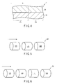
- FIG. 2 is a schematic view showing an example of the diesel exhaust gas purification system using the diesel exhaust gas purification catalyst shown in FIG. 1 .
- the diesel exhaust gas purification catalyst shown in FIG. 1 comprises substrate 10 and catalyst layer 20 formed on the substrate 10.
- the catalyst 1 is used by disposing on the upstream side of an exhaust gas stream with respect to denitration catalyst 2, shown in FIG. 2 .
- the diesel exhaust gas purification system S1 shown in FIG. 2 comprises the catalyst 1 and the denitration catalyst 2 to which the exhaust gas that has passed through the catalyst 1 is supplied.
- the substrate 10 for example, a monolithic-honeycomb type substrate is used.
- the substrate 10 is made of a ceramic such as cordierite.
- the catalyst layer 20 comprises a carrier, a noble metal and/or an oxide thereof supported by the carrier, and a composite oxide of cerium and one or more Group III and/or Group IV elements.
- the noble metal and/or an oxide thereof plays a role to catalyze a reaction for purifying exhaust gas, especially the oxidation reaction between HC and CO.
- the noble metal for example, platinum group elements such as platinum (Pt), palladium (Pd) and rhodium (Rh) are used. A plurality of kinds of elements may also be used as the noble metal.
- the composite oxide of cerium and one or more Group III and/or Group IV elements plays a role to adsorb NO x in the exhaust gas at a low temperature region and release NO x at a high temperature region.
- the denitration catalyst 2 disposed on the downstream side of the catalyst 1 cannot exhibit excellent NO x purification performance at a temperature region lower than the activation temperature (for example, 200°C).
- the catalyst 1 comprising the composite oxide when the catalyst 1 comprising the composite oxide is disposed on the upstream side, the NO x in the exhaust gas can be retained in the catalyst 1 until the temperature of the exhaust gas becomes sufficiently high. Therefore, it is possible to improve the apparent NO x purification performance of the denitration catalyst 2.
- the composite oxide is typically a composite oxide of cerium and one or more lanthanoid and/or actinoid other than cerium.
- the composite oxide is a composite oxide of cerium and praseodymium, or a composite oxide of cerium, lanthanum and praseodymium.
- the ratio of cerium in the composite oxide is, for example, in the range of from 55% by mass to 95% by mass in terms of oxide, and typically in the range of from 70% by mass to 90% by mass in terms of oxide.
- the temperature at which release of NO x occurs can suitably be adjusted by varying the ratio. Namely, by changing this ratio, NO x can be released from the catalyst 1 at a temperature that conforms to the activation temperature of the denitration catalyst 2 that is used in combination with the catalyst 1.
- the composite oxide has a specific surface area of, for example, 150 m 2 /g or more.
- the composite oxide has a specific surface area of, for example, 180 m 2 /g or more, typically 200 m 2 /g or more. Namely, the composite oxide has a relatively high specific surface area. Therefore, it has a large contact surface area with NO x in exhaust gas, and the adsorption thereof readily occurs.
- the "specific surface area” can be obtained from an N 2 adsorption isotherm measured at 77.4 K. Specifically, at first, the amount of nitrogen gas adsorbed on active carbon (mL/mL) is measured for every pressure P (mmHg) of nitrogen gas of 77.4 K (boiling point of nitrogen) while gradually increasing the pressure P in the nitrogen gas. Then, relative pressure P/P 0 is obtained as a value obtained by dividing the pressure P (mmHg) by the saturated vapor pressure P 0 (mmHg) of the nitrogen gas, and the amount of adsorbed nitrogen gas against respective relative pressure P/P 0 is plotted to give an adsorption isotherm. Then, a BET plot is prepared based on this adsorption isotherm, and a BET specific surface area is determined. Thus, the above "specific surface area" is obtained.
- the composite oxide may be supported by the carrier together with the noble metal and/or an oxide thereof.
- the apparent specific surface area of the composite oxide can be improved. Namely, the NO x adsorption performance of the composite oxide can further be improved.
- the mass ratio of the composite oxide in the catalyst layer 20 is adjusted to, for example, from 10% by mass to 85% by mass.
- excellent NO x adsorption performance may sometimes not be achieved.
- excellent HC and CO purification performance may sometimes not be achieved.
- the catalyst layer 20 may further comprise zeolite.
- Zeolite has a high specific surface area and excellent adsorption performance for HC in exhaust gas. Therefore, the HC purification performance of the catalyst 1 can further be improved by incorporating zeolite.
- zeolite for example, type- ⁇ zeolite ( ⁇ zeolite), mordenite, ZSM-5, or a mixture thereof is used.
- the ratio of zeolite in the catalyst layer 20 is adjusted to, for example, the range of from 40% by mass to 80% by mass, typically the range of from 50% by mass to 80% by mass.
- the catalyst layer 20 may further comprise a binder.
- the binder plays a role to improve the durability of the catalyst 1 by strengthen the binding among the carrier particles and the binding between the carrier particles and the noble metal and/or an oxide thereof.
- the binder for example, an alumina sol, a titania sol or a silica sol is used.
- the catalyst layer 20 may be of a monolayer structure or of a multilayer structure.
- FIG. 3 is a cross-sectional view schematically showing a variation of the diesel exhaust gas purification catalyst shown in FIG. 1 .
- the diesel exhaust gas purification catalyst 1 shown in FIG. 3 has the same constitution as the diesel exhaust gas purification catalyst shown in FIG. 1 , except that the catalyst layer 20 comprises a first catalyst layer 20A formed on the substrate 10 and a second catalyst layer 20B formed on the first catalyst layer 20A.
- the kinds, contents per unit surface area, etc. of the component such as the carrier, the noble metal and/or an oxide thereof, the composite oxide, zeolite and the binder differ from each other.
- the NO x adsorption performance, exhaust gas purification performance of the catalyst 1, and the apparent exhaust gas purification performance of the catalyst 2 that is disposed on the downstream side of the catalyst 1 can be optimized.
- the first catalyst layer 20A and the second catalyst layer 20B differ from each other in, for example, the composite oxide content in the substrate per unit volume (hereinafter also referred to as composite oxide content).
- composite oxide content the composite oxide content in the substrate per unit volume
- the second catalyst layer 20B includes a larger content of the composite oxide per unit volume of the substrate as compared to that in the first catalyst layer 20A.
- the first catalyst layer 20A does not have to include the composite oxide.
- the second catalyst layer 20B contacts with NO x molecules in the exhaust gas more readily than the first catalyst layer 20A does. Furthermore, since the composite oxide is present in a relatively large amount in the second catalyst layer 20B, the composite oxide readily contacts with NO x molecules. Therefore, in this case, the NO x purification performance of the catalyst is improved. Furthermore, a CO molecule is relatively small in size. Therefore, it is considered that many of the CO molecules in the exhaust gas pass through the second catalyst layer 20B and react in the first catalyst layer 20A. Therefore, even in the case when the constitution as mentioned above is adopted, excellent CO purification performance can be maintained.
- FIG. 4 is a cross-sectional view schematically showing another variation of the diesel exhaust gas purification catalyst shown in FIG. 1 .
- the catalyst 1 comprises a first part P1 to which exhaust gas is fed, and a second part P2 to which the exhaust gas that has passed through the first part P1 is fed. Namely, the first part P1 is positioned on the upstream side of the exhaust gas stream, and the second part P2 is positioned on the downstream side of the exhaust gas stream.
- the catalyst 1 is also used by disposing on the upstream side of the exhaust gas stream with respect to the denitration catalyst 2 shown in FIG. 2 .
- the NO x adsorption performance of the composite oxide is decreased. This phenomenon is particularly significant in the first part P1 positioned on the upstream side of the exhaust gas stream. Furthermore, the first part P1 has a higher heat load than that of the second part P2. Therefore, it is advantageous that the composite oxide is included in a larger content in the second part P2 positioned on the downstream side of the exhaust gas stream.
- the catalyst 1 by purifying PM in the first part P1 of the catalyst 1 to some extent, it is possible to make a decrease in the NO x adsorption performance due to adsorption of PM, clogging by PM, and the like difficult to occur in the second part P2 that has a larger content of the composite oxide per unit volume. Furthermore, by doing so, the exhaust gas in which large amounts of CO and HC have been purified in the first part P1 is flown into the second part P2. Therefore, by adopting such a constitution, the apparent NO x adsorption performance of the denitration catalyst 2 can further be improved.
- the ratio of the composite oxide content in the second part P2 relative to the composite oxide content in the first part P1 is, for example, within the range from 1.5 to 9.0, typically within the range from 4.0 to 9.0.
- FIG. 5 is a schematic drawing showing a variation of the diesel exhaust gas purification system shown in FIG. 2 .
- FIG. 6 is a schematic view showing another variation of the diesel exhaust gas purification system shown in FIG. 2 .
- the system S2 shown in FIG. 5 comprises a diesel oxide catalyst 100, the diesel exhaust gas purification catalyst 1 to which the exhaust gas that has passed through the catalyst 100 is supplied, and a denitration catalyst 300 to which the exhaust gas that has passed through the diesel exhaust gas purification catalyst 1 is supplied.
- the diesel exhaust gas purification catalyst 1 is disposed between the diesel oxidizing catalyst 100 and the denitration catalyst 300.
- the diesel exhaust gas purification catalyst 1 comprises the above composite oxide, it can adsorb NO x in the exhaust gas at a temperature region whose temperature being lower than the activation temperature of the denitration catalyst 300, the activation temperature being, for example, 200°C. Therefore, the NO x in the exhaust gas can be retained in the diesel exhaust gas purification catalyst 1 until the temperature of the exhaust gas is sufficiently raised. Therefore, by adopting such constitution, the apparent NO x purification performance of the denitration catalyst 300 can be improved.
- the exhaust gas that has passed through the diesel oxidizing catalyst 100 is supplied to the diesel exhaust gas purification catalyst 1.
- the exhaust gas in which PM has been at least partially removed by the diesel oxidizing catalyst 100 is supplied to the diesel exhaust gas purification catalyst 1. Therefore, a decrease in the NO x adsorption performance of the diesel exhaust gas purification catalyst 1 due to adsorption of PM, clogging by PM, and the like is difficult to occur. Namely, the apparent NO x adsorption performance of the denitration catalyst 300 can be improved.
- the system S3 shown in FIG. 6 further comprises a diesel particulate filter (DPF) 400.
- the DPF plays a role to purify the PM emitted from the diesel engine.
- a wall-flow type honeycomb is used as the DPF.
- the DPF 400 is disposed between the diesel oxidizing catalyst 100 and the diesel exhaust gas purification catalyst 1.
- the exhaust gas passes the DPF 400 before it is supplied to the diesel exhaust gas purification catalyst 1. Therefore, the PM emitted from the diesel engine is purified not only by the diesel oxidizing catalyst 100 but by the DPF 400. Therefore, a decrease in the NO x adsorption performance of the diesel exhaust gas purification catalyst 1 due to adsorption of PM and the like is further difficult to occur. Namely, the apparent NO x adsorbing performance of the denitration catalyst 300 is further improved.
- the diesel exhaust gas purification system may comprise the diesel exhaust gas purification catalyst 1, the diesel oxidizing catalyst 100 to which the exhaust gas that has passed through the diesel exhaust gas purification catalyst 1 is supplied, and the denitration catalyst 300 to which the exhaust gas that has passed through the diesel oxidizing catalyst 100 is supplied.
- the system may further comprise a DPF between the diesel oxidizing catalyst 100 and the denitration catalyst 300.
- composite oxide A A composite oxide of cerium and praseodymium was prepared. The ratio of cerium in this composite oxide was adjusted to 90% by mass in terms of oxide. The specific surface area of the obtained composite oxide was 150 m 2 /g.
- this composite oxide is referred to as "composite oxide A”.
- slurry A 100 g of the catalyst powder A, 50 g of the composite oxide A, 50 g of an alumina sol and 100 g of pure water were mixed to prepare a slurry.
- this slurry is referred to as "slurry A”.
- a diesel exhaust gas purification catalyst was prepared in a similar manner to that explained for the catalyst C1, except that the slurry B was used instead of the slurry A.
- this catalyst is referred to as "catalyst C2".
- slurry C 100 g of the catalyst powder A, 50 g of an alumina sol, and 100 g of pure water were mixed to prepare a slurry.
- this slurry is referred to as "slurry C”.
- the catalysts C1 to C3 were subjected to a durability test in an electric furnace. Specifically, the catalysts C1 to C3 were heated at 750°C for 5 hours in air.
- FIG. 7 is a graph showing the results of the measurements of the NO x adsorption amounts of the diesel exhaust gas purification catalysts.
- FIG. 8 is a graph showing the measurement result of the HC and CO conversion of the diesel exhaust gas purification catalysts.
- the catalyst C2 showed a similar HC and CO purification performance to that of the catalyst C3. Furthermore, although the catalyst C1 had a slightly lower HC and CO conversion as compared to that of the catalyst C3, it showed excellent HC and CO purification performance.
- the catalysts C1 and C2 had more excellent functionality to improve the NO x purification performance of the denitration catalyst as compared to the catalyst C3. Specifically, it was found that the catalyst C2 was further excellent in this function as compared to the catalyst C1.
- a composite oxide of cerium, lanthanum and praseodymium was prepared.
- the ratio of cerium in this composite oxide was adjusted to 90% by mass in terms of oxide.
- the ratio of lanthanum in this composite oxide was adjusted to 5% by mass in terms of oxide.
- the specific surface area of the obtained composite oxide was 180 m 2 /g.
- this composite was referred to as "composite oxide Ox1".
- slurry S1 20 g of alumina, 120 g of the composite oxide Ox1, 135 g of zeolite, 100 g of an alumina sol, 100 g of pure water, and a platinum nitrate solution containing 8 g of platinum, a palladium nitrate solution containing 4 g of palladium, and a rhodium nitrate solution containing 2 g of rhodium were mixed to prepare a slurry.
- the slurry is referred to as "slurry S1".
- a monolithic honeycomb carrier having a volume of 0.035 L was coated with the slurry S1. This was dried at 250°C for 1 hour, and calcined at 500°C for 1 hour.
- a diesel exhaust gas purification catalyst was prepared in this manner. Hereinafter, this catalyst is referred to as "catalyst C4".
- a diesel exhaust gas purification catalyst was prepared in a similar manner to that explained for the catalyst C4, except that 120 g of the composite oxide Ox2 was used instead of 120 g of the composite oxide Ox1.
- this catalyst is referred to as "catalyst C5".
- a composite oxide of cerium and zirconium was prepared.
- the ratio of cerium in this composite oxide was adjusted to 80% by mass in terms of oxide.
- the specific surface area of the obtained composite oxide was 80 m 2 /g.
- this composite was referred to as "composite oxide Ox3".
- a diesel exhaust gas purification catalyst was prepared in a similar manner to that explained for the catalyst C4, except that 120 g of the composite oxide Ox3 was used instead of 120 g of the composite oxide Ox1.
- this catalyst is referred to as "catalyst C6".
- a composite oxide of cerium and praseodymium was prepared.
- the ratio of cerium in this composite oxide was adjusted to 90% by mass in terms of oxide.
- the specific surface area of the obtained composite oxide was 190 m 2 /g.
- this composite was referred to as "composite oxide Ox4".
- a diesel exhaust gas purification catalyst was prepared in a similar manner to that explained for the catalyst C4, except that 120 g of the composite oxide Ox4 was used instead of 120 g of the composite oxide Ox1.
- this catalyst is referred to as "catalyst C7".
- a composite oxide of cerium and lanthanum was prepared.
- the ratio of cerium in this composite oxide was adjusted to 90% by mass in terms of oxide.
- the specific surface area of the obtained composite oxide was 165 m 2 /g.
- this composite was referred to as "composite oxide Ox5".
- a diesel exhaust gas purification catalyst was prepared in a similar manner to that explained for the catalyst C4, except that 120 g of the composite oxide Ox5 was used instead of 120 g of the composite oxide Ox1.
- this catalyst is referred to as "catalyst C8".
- a composite oxide of cerium, zirconium, lanthanum, and praseodymium was prepared.
- the ratio of cerium in this composite oxide was adjusted to 80% by mass in terms of oxide.
- the ratio of zirconium in this composite oxide was adjusted to 10% by mass in terms of oxide.
- the ratio of lanthanum in this composite oxide was adjusted to 5% by mass in terms of oxide.
- the specific surface area of the obtained composite oxide was 150 m 2 /g.
- this composite was referred to as "composite oxide Ox6".
- a diesel exhaust gas purification catalyst was prepared in a similar manner to that explained for the catalyst C4, except that 120 g of the composite oxide Ox6 was used instead of 120 g of the composite oxide Ox1.
- this catalyst is referred to as "catalyst C9".
- a composite oxide of cerium, praseodymium, and neodymium was prepared.
- the ratio of cerium in this composite oxide was adjusted to 90% by mass in terms of oxide.
- the ratio of praseodymium in this composite oxide was adjusted to 5% by mass in terms of oxide.
- composite oxide Ox7 The specific surface area of the obtained composite oxide was 145 m 2 /g.
- composite oxide Ox7 this composite was referred to as "composite oxide Ox7".
- a diesel exhaust gas purification catalyst was prepared in a similar manner to that explained for the catalyst C4, except that 120 g of the composite oxide Ox7 was used instead of 120 g of the composite oxide Ox1.
- this catalyst is referred to as "catalyst C10".
- a diesel exhaust gas purification catalyst was prepared in a similar manner to that explained for the catalyst C4, except that 120 g of the composite oxide Ox8 was used instead of 120 g of the composite oxide Ox1.
- this catalyst is referred to as "catalyst C11".
- a diesel exhaust gas purification catalyst was prepared in a similar manner to that explained for the catalyst C4, except that 78 g of the composite oxide Ox9, 6 g of barium acetate (the weight in terms of BaO 2 ) and 30 g of alumina were used instead of 120 g of the composite oxide Ox1.
- this catalyst is referred to as "catalyst C12".
- Each of the catalysts C4 to C12 was subjected to a similar durability test to that mentioned previously for the catalysts C1 to C3.
- the diesel exhaust gas purification systems that have been explained with reference to FIG. 2 were prepared by using each of the catalysts C4 to C12 after the durability test. Namely, systems each comprising each of the catalysts C4 to C12 and a denitration catalyst to which the exhaust gas that has passed through each of the catalysts C4 to C12 is supplied were manufactured. Thereafter, the conversions of CO, HC and NO x at 200°C were measured for each of these systems.
- Table 1 is a table in which the physical properties of the catalyst C4 to C12 are summarized.
- a diesel exhaust gas purification catalyst was prepared in a similar manner to that explained for the catalyst C4, except that 105 g of the composite oxide Ox1 was used instead of 120 g of the composite oxide Ox1, and 150 g of zeolite was used instead of 200 g of zeolite.
- this catalyst is referred to as "catalyst C14".
- a diesel exhaust gas purification catalyst was prepared in a similar manner to that explained for the catalyst C4, except that 180 g of the composite oxide Ox1 was used instead of 120 g of the composite oxide Ox1, and 75 g of zeolite was used instead of 200 g of zeolite.
- this catalyst is referred to as "catalyst C15".
- a diesel exhaust gas purification catalyst was prepared in a similar manner to that explained for the catalyst C4, except that 225 g of the composite oxide Ox1 was used instead of 120 g of the composite oxide Ox1, and the use of zeolite was omitted.
- this catalyst is referred to as "catalyst C16".
- Each of the catalysts C13 to C16 was subjected to a similar durability test to that mentioned previously for the catalysts C1 to C3.
- the diesel exhaust gas purification system that has been explained with reference to FIG. 2 was prepared by using each of the catalysts C13 to C16 after the durability test. Namely, systems each comprising each of the catalysts C13 to C16 and a denitration catalyst to which the exhaust gas that has passed through each of the catalysts C13 to C16 is supplied were manufactured. Thereafter, the conversions of CO, HC and NO x at 200°C were measured for each of these systems in a similar manner to that explained previously for the systems comprising the catalysts C4 to C12.
- Table 2 is a table in which the physical properties of the catalysts C13 to C16 and the catalyst C4 are summarized. The meanings of the respective descriptions in Table 2 are the same to those in Table 1.
- slurry S2 10 g of alumina, 90 g of the composite oxide Ox1, 67.5 g of zeolite, 50 g of an alumina sol, 50 g of pure water, and a platinum nitrate solution containing 4 g of platinum, a palladium nitrate solution containing 2 g of palladium, and a rhodium nitrate solution containing 1 g of rhodium were mixed to prepare a slurry.
- the slurry is referred to as "slurry S2".
- a slurry was prepared in a similar manner to that for the slurry S2, except that 30 g of the composite oxide Ox1 was used instead of 90 g of the composite oxide Ox1.
- the slurry is referred to as "slurry S3".
- a monolithic honeycomb carrier having a volume of 0.035 L was coated with the slurry A. This was dried at 250°C for 1 hour, and calcined at 500°C for 1 hour. A first catalyst layer was thus formed on a substrate.
- a diesel exhaust gas purification catalyst was prepared in the manner mentioned above. Hereinafter, this catalyst is referred to as "catalyst C17".
- a slurry was prepared in a similar manner to that for the slurry S2, except that 60 g of the composite oxide Ox1 was used instead of 90 g of the composite oxide Ox1.
- the slurry is referred to as "slurry S4".
- a diesel exhaust gas purification catalyst was prepared in a similar manner to that for the catalyst C17, except that the slurry S4 was used instead of the slurries S2 and S3.
- this catalyst is referred to as "catalyst C18".
- a diesel exhaust gas purification catalyst was prepared in a similar manner to that for the catalyst C17, except that the slurry S2 was used instead of the slurry S3, and the slurry S3 was used instead of the slurry S2.
- this catalyst is referred to as "catalyst C19".
- a monolithic honeycomb carrier substrate having a volume of 0.035 L was coated with the slurry S3 up to the position at 50% from the upstream end of the substrate, and dried at 250°C for 1 hour.
- the substrate was then coated with the slurry S2 up to the position at 50% from the downstream end of the substrate, and dried at 250°C for 1 hour.
- the obtained was then calcined at 500°C for 1 hour.
- a diesel exhaust gas purification catalyst was manufactured in this manner. Hereinafter, this catalyst is referred to as "catalyst C20".
- a diesel exhaust gas purification catalyst was prepared in a similar manner to that for the catalyst C20, except that the slurry S4 was used instead of the slurries S2 and S3.
- this catalyst is referred to as "catalyst C21".
- Each of the catalysts C17 to C22 was subjected to a similar durability test to that mentioned previously for the catalysts C1 to C3.
- the diesel exhaust gas purification system that has been explained with reference to FIG. 2 was prepared by using each of the catalysts C17 to C22 after the durability test. Namely, systems each comprising each of the catalysts C17 to C22 and a denitration catalyst to which the exhaust gas that has passed through each of the catalysts C17 to C22 is supplied were manufactured. Thereafter, the conversions of CO, HC and NO x at 200°C were measured for each of these systems in a similar manner to that explained previously for the systems comprising the catalysts C4 to C12.
- a composite oxide of cerium, lanthanum, and praseodymium was prepared.
- the ratio of cerium in this composite oxide was adjusted to 90% by mass in terms of oxide.
- the ratio of lanthanum in this composite oxide was adjusted to 5% by mass in terms of oxide.
- the specific surface area of the obtained composite oxide was 120 m 2 /g.
- this composite was referred to as "composite oxide Ox10".
- a composite oxide of cerium, lanthanum, and praseodymium was prepared.
- the ratio of cerium in this composite oxide was adjusted to 90% by mass in terms of oxide.
- the ratio of lanthanum in this composite oxide was adjusted to 5% by mass in terms of oxide.
- the specific surface area of the obtained composite oxide was 150 m 2 /g.
- this composite was referred to as "composite oxide Ox11".
- a diesel exhaust gas purification catalyst was prepared in a similar manner to that explained for the catalyst C4, except that 120 g of the composite oxide Ox11 was used instead of 120 g of the composite oxide Ox1.
- this catalyst is referred to as "catalyst C24".
- a composite oxide of cerium, lanthanum, and praseodymium was prepared.
- the ratio of cerium in this composite oxide was adjusted to 90% by mass in terms of oxide.
- the ratio of lanthanum in this composite oxide was adjusted to 5% by mass in terms of oxide.
- the specific surface area of the obtained composite oxide was 210 m 2 /g.
- this composite was referred to as "composite oxide Ox12".
- a diesel exhaust gas purification catalyst was prepared in a similar manner to that explained for the catalyst C4, except that 120 g of the composite oxide Ox12 was used instead of 120 g of the composite oxide Ox1.
- this catalyst is referred to as "catalyst C25".
- Each of the catalysts C23 to C25 was subjected to a similar durability test to that mentioned previously for the catalysts C1 to C3.
- the diesel exhaust gas purification system that has been explained with reference to FIG. 2 was prepared by using each of the catalysts C23 to C25 after the durability test. Namely, systems each comprising each of the catalysts C23 to C25 and a denitration catalyst to which the exhaust gas that has passed through each of the catalysts C23 to C25 is supplied were manufactured. Thereafter, the conversions of CO, HC and NO x at 200°C were measured for each of these systems in a similar manner to that explained previously for the systems comprising the catalysts C4 to C12.
- Table 5 is a table in which the physical properties of the catalysts C23 to C25 and the catalyst C4 are summarized. The meanings of the respective descriptions in Table 5 are similar to those in Table 1.
- alumina A1 Alumina having a specific surface area of 180 m 2 /g was prepared. Hereinafter, this alumina is referred to as "alumina A1".
- a diesel exhaust gas purification catalyst was prepared in a similar manner to that explained for the catalyst C4, except that 120 g of the alumina Al was used instead of 120 g of the composite oxide Ox1.
- this catalyst is referred to as "catalyst C27".
- a composite oxide of cerium and aluminum was prepared.
- the ratio of cerium in this composite oxide was adjusted to 90% by mass in terms of oxide.
- the specific surface area of the obtained composite oxide was 180 m 2 /g.
- this composite was referred to as "composite oxide Ox13.
- a diesel exhaust gas purification catalyst was prepared in a similar manner to that explained for the catalyst C4, except that 120 g of the composite oxide Ox13 was used instead of 120 g of the composite oxide Ox1.
- this catalyst is referred to as "catalyst C28".
- Each of the catalysts C26 to C31 was subjected to a similar durability test to that mentioned previously for the catalysts C1 to C3.
- Table 6 is a table in which the physical properties of the catalysts C26 to C31 and the catalyst C4 are summarized.
- MIX means that a mixture of a plurality of oxides was used.
- the meanings of other descriptions in Table 6 are similar to those in Table 1.
Landscapes
- Chemical & Material Sciences (AREA)
- Engineering & Computer Science (AREA)
- Chemical Kinetics & Catalysis (AREA)
- Materials Engineering (AREA)
- Organic Chemistry (AREA)
- Combustion & Propulsion (AREA)
- Biomedical Technology (AREA)
- General Chemical & Material Sciences (AREA)
- Oil, Petroleum & Natural Gas (AREA)
- Analytical Chemistry (AREA)
- Environmental & Geological Engineering (AREA)
- Health & Medical Sciences (AREA)
- Mechanical Engineering (AREA)
- General Engineering & Computer Science (AREA)
- Crystallography & Structural Chemistry (AREA)
- Catalysts (AREA)
- Exhaust Gas After Treatment (AREA)
- Exhaust Gas Treatment By Means Of Catalyst (AREA)
Abstract
Description
- The present invention relates to a technique for exhaust gas purification.
- In recent years, exhaust gas regulations for automobiles and the like have been enforced. To cope with these regulations, various exhaust gas purification catalysts which are configured to efficiently remove hydrocarbons (HC), carbon monoxides (CO), nitrogen oxides (NOx) and the like in exhaust gas have been developed (see, for example, Non-patent Document 1).
- However, conventional exhaust gas purification catalysts may not achieve sufficient purification performance for exhaust gas such as NOx.
- Non-patent Document 1: "Catalyst Utilization Dictionary", Editorial Board of Catalyst Utilization Dictionary ed., Kogyo Chosakai Publishing Co., Ltd. (2004)
- An object of the present invention is to achieve excellent exhaust gas purification performance, and especially to achieve excellent NOx purification performance.
- According to a first aspect of the present invention, there is provided a diesel exhaust gas purification catalyst, comprising: a substrate; and a catalyst layer formed on the substrate, the catalyst layer comprising a carrier, a noble metal and/or an oxide thereof supported by the carrier, and a composite oxide of cerium and one or more Group III and/or Group IV elements, wherein the catalyst when in use is disposed on an upstream side of an exhaust gas stream with respect to a denitration catalyst.
- According to a second aspect of the present invention, there is provided a diesel exhaust gas purification system, comprising: the diesel exhaust gas purification catalyst according to the first aspect; and a denitration catalyst to which exhaust gas that has passed through the diesel exhaust gas purification catalyst is fed.
-
-
FIG. 1 is a cross-sectional view schematically showing the diesel exhaust gas purification catalyst according to an embodiment of the present invention. -
FIG. 2 is a schematic view showing an example of the diesel exhaust gas purification system using the diesel exhaust gas purification catalyst shown inFIG. 1 . -
FIG. 3 is a cross-sectional view schematically showing a variation of the diesel exhaust gas purification catalyst shown inFIG. 1 . -
FIG. 4 is a cross-sectional view schematically showing another variation of the diesel exhaust gas purification catalyst shown inFIG. 1 . -
FIG. 5 is a schematic drawing showing a variation of the diesel exhaust gas purification system shown inFIG. 2 . -
FIG. 6 is a schematic view showing another variation of the diesel exhaust gas purification system shown inFIG. 2 . -
FIG. 7 is a graph showing the results of the measurements of the NOx adsorption amounts of the diesel exhaust gas purification catalysts. -
FIG. 8 is a graph showing the measurement result of the HC and CO conversion of the diesel exhaust gas purification catalysts. - The inventors have made intensive studies aiming at solving the problems mentioned above. During the process therefor, the inventors have found that a denitration catalyst for purifying NOx may not achieve sufficient NOx purification performance at a temperature lower than a certain temperature (hereinafter referred to as an activation temperature; for example, about 200°C). Namely, the inventors have found that when a diesel engine in which the temperature of exhausted gas emitted therefrom is relatively low is used, a denitration catalyst is not likely to achieve sufficient NOx purification performance. Therefore, the present inventors have developed a diesel exhaust gas purification catalyst focusing on the following points. As a result, the present inventors have obtained an idea of disposing a catalyst comprising a composite oxide of cerium and one or more Group III and/or Group IV elements on the upstream side of an exhaust gas stream with respect to a denitration catalyst.
- Cerium has a property that its ion valency is readily varied as compared to other elements. Therefore, the valency tends to be varied between Ce3+ and Ce4+, for example, in cerium oxide. Therefore, cerium oxide causes the following reactions in accordance with the variation of the concentration of surrounding oxygen.
2CeO2→Ce2O3+1/2O2 (1)
Ce2O3+1/2O2→2CeO2 (2)
- Namely, when the concentration of surrounding oxygen is low, oxygen is released by the reaction of (1). On the other hand, when the concentration of surrounding oxygen is high, oxygen is absorbed by the reaction of (2). Thus, cerium oxide has a performance of adjusting the concentration of surrounding oxygen by releasing and absorbing oxygen reversibly. This performance is generally referred to as oxygen storage capacity.
- Cerium oxide has a crystal structure in which atoms are packed densely. Therefore, it is considered that diffusion of oxygen in the crystal is hard to occur. Therefore, the storage and release of oxygen is expected to occur only around the surface of cerium oxide.
- Therefore, a composite oxide of cerium oxide and other metal oxide has been conventionally used as an oxygen storage material. In such composite oxide, relatively large gaps are formed in the crystal due to the different sizes of the atoms of cerium and other metal elements. Therefore, it is considered that diffusion of oxygen in the crystal occurs more easily as compared to cerium oxide. Accordingly, it is expected that not only the vicinity of the surface of the crystal but also the inside of the crystal contribute to the storage and release of oxygen.
- In the present embodiment, as mentioned above, a composite oxide of cerium and one or more Group III and/or Group IV elements is used. It is considered that the Group III and/or Group IV elements are strongly bound to oxygen. Furthermore, it is expected that the Group III and/or Group IV elements cause less valency variation as compared to cerium. Therefore, in a low temperature region where heat energy is small (for example, a temperature region whose temperature being lower than the activation temperature), it is expected that the reaction for releasing oxygen that corresponds to the (1) is relatively hard to occur. Namely, it is considered that oxygen is readily retained in the crystal at a low temperature region in the composite oxide used in the present embodiment.
- At least a part of the elements bound to the stored oxygen has a 4f orbital and/or a 5d orbital having high electron-acceptability. Namely, at least a part of these elements has a 4f orbit and/or a 5d orbital that is not occupied by electrons or is occupied only by an unpaired electron. Furthermore, it is considered that the orbital occupied by the electrons possessed by NOx can form a bonding molecular orbital between these orbitals. Therefore, in this case, the element may act as an adsorbing site for adsorbing NOx. Namely, it is considered that this composite oxide may act as a NOx storage material at a low temperature region.
- On the other hand, it is considered that the stored oxygen is released from the composite oxide at a high temperature region at which heat energy is high (for example, a temperature region whose temperature being the activation temperature or higher).
- Therefore, it is expected that the valency of the elements that are bound to the oxygen is decreased and the electron-acceptability thereof is also decreased. Namely, it is expected that the binding between these elements and NOx becomes relatively weak. Furthermore, at the high temperature region, the heat oscillation of the adsorbed NOx also becomes active. Therefore, it is considered that this composite oxide releases not only the stored oxygen but also the adsorbed NOx at the high temperature region.
- As mentioned above, it is expected that the composite oxide of the present embodiment has a function to adsorb NOx at a low temperature region (for example, a temperature region whose temperature being lower than the activation temperature) and to release NOx at a high temperature region (for example a temperature region whose temperature being the activation temperature or higher). Therefore, the present inventors conceived that the problems of the denitration catalyst can be eliminated by disposing a catalyst comprising this composite oxide on the upstream side of an exhaust gas stream with respect to the denitration catalyst.
- Namely, when the temperature of exhaust gas is low, the NOx in the exhaust gas is adsorbed on the catalyst disposed on the upstream side. Then, when the temperature of the exhaust gas is raised, the NOx adsorbed on the catalyst disposed on the upstream side is released and flown into the denitration catalyst disposed on the downstream side. Namely, the exhaust gas at a relatively high temperature, for example, at a temperature being the activation temperature or higher is mainly flown into the denitration catalyst. Therefore, the denitration catalyst can exhibit excellent NOx purification performance at a broader temperature range as compared to conventional ones.
- Hereinafter, the embodiments of the present invention are explained with reference to drawings. Throughout the drawings, the same reference numerals are used for constitutional elements that exhibit the same or similar function, and redundant explanations have been omitted. Furthermore, as used herein, the "composite oxide" means that a plurality of oxides form a solid solution rather than a mere physical mixture of oxides.
-
FIG. 1 is a cross-sectional view schematically showing the diesel exhaust gas purification catalyst according to an embodiment of the present invention.FIG. 2 is a schematic view showing an example of the diesel exhaust gas purification system using the diesel exhaust gas purification catalyst shown inFIG. 1 . - The diesel exhaust gas purification catalyst shown in
FIG. 1 comprisessubstrate 10 andcatalyst layer 20 formed on thesubstrate 10. Thecatalyst 1 is used by disposing on the upstream side of an exhaust gas stream with respect to denitration catalyst 2, shown inFIG. 2 . Namely, the diesel exhaust gas purification system S1 shown inFIG. 2 comprises thecatalyst 1 and the denitration catalyst 2 to which the exhaust gas that has passed through thecatalyst 1 is supplied. - As the
substrate 10, for example, a monolithic-honeycomb type substrate is used. Typically, thesubstrate 10 is made of a ceramic such as cordierite. - The
catalyst layer 20 comprises a carrier, a noble metal and/or an oxide thereof supported by the carrier, and a composite oxide of cerium and one or more Group III and/or Group IV elements. - The carrier plays roles to increase the specific surface area of the noble metal and/or an oxide thereof, and to dissipate the heat generation due to the reaction to suppress the sintering of the noble metal and/or an oxide thereof. The carrier comprises, for example, at least one element selected from aluminum (Al), titanium (Ti), zirconium (Zr) and silicon (Si). Typically, oxides such as alumina, titania, zirconia and silica are used as the carrier.
- The noble metal and/or an oxide thereof plays a role to catalyze a reaction for purifying exhaust gas, especially the oxidation reaction between HC and CO. As the noble metal, for example, platinum group elements such as platinum (Pt), palladium (Pd) and rhodium (Rh) are used. A plurality of kinds of elements may also be used as the noble metal.
- As mentioned above, the composite oxide of cerium and one or more Group III and/or Group IV elements plays a role to adsorb NOx in the exhaust gas at a low temperature region and release NOx at a high temperature region. As is previously mentioned, the denitration catalyst 2 disposed on the downstream side of the
catalyst 1 cannot exhibit excellent NOx purification performance at a temperature region lower than the activation temperature (for example, 200°C). On the other hand, when thecatalyst 1 comprising the composite oxide is disposed on the upstream side, the NOx in the exhaust gas can be retained in thecatalyst 1 until the temperature of the exhaust gas becomes sufficiently high. Therefore, it is possible to improve the apparent NOx purification performance of the denitration catalyst 2. - As the Group III element included in the composite oxide other than cerium, for example, yttrium (Y), a lanthanoid and/or an actinoid is used. As the lanthanoid, for example, lanternum (La), praseodymium (Pr) and/or neodymium (Nd) is used. As the Group IV element, for example, titanium (Ti) and/or zirconium (Zr) is used. The composite oxide may further include barium (Ba) and/or aluminum (Al).
- The composite oxide is typically a composite oxide of cerium and one or more lanthanoid and/or actinoid other than cerium. For example, the composite oxide is a composite oxide of cerium and praseodymium, or a composite oxide of cerium, lanthanum and praseodymium. The ratio of cerium in the composite oxide is, for example, in the range of from 55% by mass to 95% by mass in terms of oxide, and typically in the range of from 70% by mass to 90% by mass in terms of oxide. The temperature at which release of NOx occurs can suitably be adjusted by varying the ratio. Namely, by changing this ratio, NOx can be released from the
catalyst 1 at a temperature that conforms to the activation temperature of the denitration catalyst 2 that is used in combination with thecatalyst 1. - The composite oxide has a specific surface area of, for example, 150 m2/g or more. The composite oxide has a specific surface area of, for example, 180 m2/g or more, typically 200 m2/g or more. Namely, the composite oxide has a relatively high specific surface area. Therefore, it has a large contact surface area with NOx in exhaust gas, and the adsorption thereof readily occurs.
- The "specific surface area" can be obtained from an N2 adsorption isotherm measured at 77.4 K. Specifically, at first, the amount of nitrogen gas adsorbed on active carbon (mL/mL) is measured for every pressure P (mmHg) of nitrogen gas of 77.4 K (boiling point of nitrogen) while gradually increasing the pressure P in the nitrogen gas. Then, relative pressure P/P0 is obtained as a value obtained by dividing the pressure P (mmHg) by the saturated vapor pressure P0 (mmHg) of the nitrogen gas, and the amount of adsorbed nitrogen gas against respective relative pressure P/P0 is plotted to give an adsorption isotherm. Then, a BET plot is prepared based on this adsorption isotherm, and a BET specific surface area is determined. Thus, the above "specific surface area" is obtained.
- The composite oxide may be supported by the carrier together with the noble metal and/or an oxide thereof. By doing so, the apparent specific surface area of the composite oxide can be improved. Namely, the NOx adsorption performance of the composite oxide can further be improved.
- The mass ratio of the composite oxide in the
catalyst layer 20 is adjusted to, for example, from 10% by mass to 85% by mass. When the amount is small, excellent NOx adsorption performance may sometimes not be achieved. When the amount is high, excellent HC and CO purification performance may sometimes not be achieved. - The
catalyst layer 20 may further comprise zeolite. Zeolite has a high specific surface area and excellent adsorption performance for HC in exhaust gas. Therefore, the HC purification performance of thecatalyst 1 can further be improved by incorporating zeolite. As the zeolite, for example, type-β zeolite (β zeolite), mordenite, ZSM-5, or a mixture thereof is used. The ratio of zeolite in thecatalyst layer 20 is adjusted to, for example, the range of from 40% by mass to 80% by mass, typically the range of from 50% by mass to 80% by mass. - The
catalyst layer 20 may further comprise a binder. The binder plays a role to improve the durability of thecatalyst 1 by strengthen the binding among the carrier particles and the binding between the carrier particles and the noble metal and/or an oxide thereof. As the binder, for example, an alumina sol, a titania sol or a silica sol is used. - The
catalyst layer 20 may be of a monolayer structure or of a multilayer structure. -
FIG. 3 is a cross-sectional view schematically showing a variation of the diesel exhaust gas purification catalyst shown inFIG. 1 . The diesel exhaustgas purification catalyst 1 shown inFIG. 3 has the same constitution as the diesel exhaust gas purification catalyst shown inFIG. 1 , except that thecatalyst layer 20 comprises afirst catalyst layer 20A formed on thesubstrate 10 and asecond catalyst layer 20B formed on thefirst catalyst layer 20A. - In these catalyst layers 20A and 20B, the kinds, contents per unit surface area, etc. of the component such as the carrier, the noble metal and/or an oxide thereof, the composite oxide, zeolite and the binder differ from each other. By doing so, the NOx adsorption performance, exhaust gas purification performance of the
catalyst 1, and the apparent exhaust gas purification performance of the catalyst 2 that is disposed on the downstream side of thecatalyst 1 can be optimized. - The
first catalyst layer 20A and thesecond catalyst layer 20B differ from each other in, for example, the composite oxide content in the substrate per unit volume (hereinafter also referred to as composite oxide content). When the NOx purification performance of thecatalyst 1 is important, the following constitution is typically adopted. Namely, thesecond catalyst layer 20B includes a larger content of the composite oxide per unit volume of the substrate as compared to that in thefirst catalyst layer 20A. In this case, thefirst catalyst layer 20A does not have to include the composite oxide. - When the
second catalyst layer 20B has a larger composite oxide content as compared to that of thefirst catalyst layer 20A, each layer mainly plays the following role. Namely, thesecond catalyst layer 20B mainly contributes to adsorption and purification of NOx. Furthermore, thefirst catalyst layer 20A mainly contributes to purification of CO and HC. - When the composite oxide content in the
second catalyst layer 20B is larger than that of thefirst catalyst layer 20A, the following advantages become available. Namely, thesecond catalyst layer 20B contacts with NOx molecules in the exhaust gas more readily than thefirst catalyst layer 20A does. Furthermore, since the composite oxide is present in a relatively large amount in thesecond catalyst layer 20B, the composite oxide readily contacts with NOx molecules. Therefore, in this case, the NOx purification performance of the catalyst is improved. Furthermore, a CO molecule is relatively small in size. Therefore, it is considered that many of the CO molecules in the exhaust gas pass through thesecond catalyst layer 20B and react in thefirst catalyst layer 20A. Therefore, even in the case when the constitution as mentioned above is adopted, excellent CO purification performance can be maintained. - When the NOx purification performance of the
catalyst 1 is important, the ratio of the composite oxide content in thesecond catalyst layer 20B with respect to the composite oxide content in thefirst catalyst layer 20A is adjusted to, for example, in the range of from 1.5 to 9.0, typically in the range of from 1.5 to 4.0. -
FIG. 4 is a cross-sectional view schematically showing another variation of the diesel exhaust gas purification catalyst shown inFIG. 1 . - The
catalyst 1 comprises a first part P1 to which exhaust gas is fed, and a second part P2 to which the exhaust gas that has passed through the first part P1 is fed. Namely, the first part P1 is positioned on the upstream side of the exhaust gas stream, and the second part P2 is positioned on the downstream side of the exhaust gas stream. Thecatalyst 1 is also used by disposing on the upstream side of the exhaust gas stream with respect to the denitration catalyst 2 shown inFIG. 2 . - In this example, the first part P1 and the second part P2 are different from each other in the composite oxide content per unit volume. Typically, the first part P1 has a lower content of the composite oxide per unit volume as compared to that of the second part P2. In this case, the first part P1 does not have to include the composite oxide.
- When the adsorption site of the composite oxide is covered by a particular material (PM) and the like emitted from a diesel engine, the NOx adsorption performance of the composite oxide is decreased. This phenomenon is particularly significant in the first part P1 positioned on the upstream side of the exhaust gas stream. Furthermore, the first part P1 has a higher heat load than that of the second part P2. Therefore, it is advantageous that the composite oxide is included in a larger content in the second part P2 positioned on the downstream side of the exhaust gas stream.
- Furthermore, by purifying PM in the first part P1 of the
catalyst 1 to some extent, it is possible to make a decrease in the NOx adsorption performance due to adsorption of PM, clogging by PM, and the like difficult to occur in the second part P2 that has a larger content of the composite oxide per unit volume. Furthermore, by doing so, the exhaust gas in which large amounts of CO and HC have been purified in the first part P1 is flown into the second part P2. Therefore, by adopting such a constitution, the apparent NOx adsorption performance of the denitration catalyst 2 can further be improved. - The ratio of the composite oxide content in the second part P2 relative to the composite oxide content in the first part P1 is, for example, within the range from 1.5 to 9.0, typically within the range from 4.0 to 9.0.
-
FIG. 5 is a schematic drawing showing a variation of the diesel exhaust gas purification system shown inFIG. 2 .FIG. 6 is a schematic view showing another variation of the diesel exhaust gas purification system shown inFIG. 2 . - The system S2 shown in
FIG. 5 comprises adiesel oxide catalyst 100, the diesel exhaustgas purification catalyst 1 to which the exhaust gas that has passed through thecatalyst 100 is supplied, and adenitration catalyst 300 to which the exhaust gas that has passed through the diesel exhaustgas purification catalyst 1 is supplied. Namely, in this system S2, the diesel exhaustgas purification catalyst 1 is disposed between thediesel oxidizing catalyst 100 and thedenitration catalyst 300. - Since the diesel exhaust
gas purification catalyst 1 comprises the above composite oxide, it can adsorb NOx in the exhaust gas at a temperature region whose temperature being lower than the activation temperature of thedenitration catalyst 300, the activation temperature being, for example, 200°C. Therefore, the NOx in the exhaust gas can be retained in the diesel exhaustgas purification catalyst 1 until the temperature of the exhaust gas is sufficiently raised. Therefore, by adopting such constitution, the apparent NOx purification performance of thedenitration catalyst 300 can be improved. - Furthermore, as mentioned above, the exhaust gas that has passed through the
diesel oxidizing catalyst 100 is supplied to the diesel exhaustgas purification catalyst 1. In this case, the exhaust gas in which PM has been at least partially removed by thediesel oxidizing catalyst 100 is supplied to the diesel exhaustgas purification catalyst 1. Therefore, a decrease in the NOx adsorption performance of the diesel exhaustgas purification catalyst 1 due to adsorption of PM, clogging by PM, and the like is difficult to occur. Namely, the apparent NOx adsorption performance of thedenitration catalyst 300 can be improved. - The system S3 shown in
FIG. 6 further comprises a diesel particulate filter (DPF) 400. The DPF plays a role to purify the PM emitted from the diesel engine. As the DPF, for example, a wall-flow type honeycomb is used. - In the system S3, the
DPF 400 is disposed between thediesel oxidizing catalyst 100 and the diesel exhaustgas purification catalyst 1. In the system S3, the exhaust gas passes theDPF 400 before it is supplied to the diesel exhaustgas purification catalyst 1. Therefore, the PM emitted from the diesel engine is purified not only by thediesel oxidizing catalyst 100 but by theDPF 400. Therefore, a decrease in the NOx adsorption performance of the diesel exhaustgas purification catalyst 1 due to adsorption of PM and the like is further difficult to occur. Namely, the apparent NOx adsorbing performance of thedenitration catalyst 300 is further improved. - In addition, the diesel exhaust gas purification system may comprise the diesel exhaust
gas purification catalyst 1, thediesel oxidizing catalyst 100 to which the exhaust gas that has passed through the diesel exhaustgas purification catalyst 1 is supplied, and thedenitration catalyst 300 to which the exhaust gas that has passed through thediesel oxidizing catalyst 100 is supplied. Furthermore, the system may further comprise a DPF between thediesel oxidizing catalyst 100 and thedenitration catalyst 300. - 100 g of alumina, 100 g of pure water, and a platinum nitrate solution containing 4 g of platinum were mixed. This was dried at 250°C, and calcined at 500°C for 3 hours in air. A catalyst powder was thus obtained. Hereinafter, this is referred to as "catalyst powder A".
- A composite oxide of cerium and praseodymium was prepared. The ratio of cerium in this composite oxide was adjusted to 90% by mass in terms of oxide. The specific surface area of the obtained composite oxide was 150 m2/g. Hereinafter, this composite oxide is referred to as "composite oxide A".
- 100 g of the catalyst powder A, 50 g of the composite oxide A, 50 g of an alumina sol and 100 g of pure water were mixed to prepare a slurry. Hereinafter, this slurry is referred to as "slurry A".
- A monolithic honeycomb carrier having a volume of 0.035 L was coated with the slurry A. This was dried at 250°C for 1 hour, and calcined at 500°C for 1 hour.
- A diesel exhaust gas purification catalyst was thus prepared. Hereinafter, this catalyst is referred to as "catalyst C1".
- First, 100 g of alumina, 50 g of the composite oxide A, 50 g of an alumina sol, 100 g of pure water, and a platinum nitrate solution containing 4 g of platinum were mixed to prepare a slurry. Hereinafter, this slurry is referred to as "slurry B".
- Then, a diesel exhaust gas purification catalyst was prepared in a similar manner to that explained for the catalyst C1, except that the slurry B was used instead of the slurry A. Hereinafter, this catalyst is referred to as "catalyst C2".
- First, 100 g of the catalyst powder A, 50 g of an alumina sol, and 100 g of pure water were mixed to prepare a slurry. Hereinafter, this slurry is referred to as "slurry C".
- Then, a diesel exhaust gas purification catalyst was prepared in a similar manner to that explained for the catalyst C1, except that the slurry C was used instead of the slurry A. Hereinafter, this catalyst is referred to as "catalyst C3".
- The catalysts C1 to C3 were subjected to a durability test in an electric furnace. Specifically, the catalysts C1 to C3 were heated at 750°C for 5 hours in air.
- The catalysts C1 to C3 after the durability test were pre-treated by heating them to 400°C. Thereafter, these catalysts C1 to C3 were put into a lean atmosphere for 2 minutes using a model gas apparatus. Then, the NOx adsorption amounts during that time were measured. The measurements were carried out at 200°C. The results are shown in
FIG. 7 . -
FIG. 7 is a graph showing the results of the measurements of the NOx adsorption amounts of the diesel exhaust gas purification catalysts. - As is apparent from
FIG. 7 , the catalysts C1 and C2 showed much more excellent NOx adsorption performance as compared to that of the catalyst C3. Specifically, the catalysts C1 and C2 had NOx adsorption amounts of 500 mg/L-NO2 or more in NO2 conversion. These adsorption amounts are, for example, sufficient for adsorbing almost the whole amount of NOx that is emitted immediately after starting an engine. In addition, the catalyst C2 showed more excellent NOx adsorption performance as compared to the catalyst C1. - A model gas comprising HC and CO was flown into the catalysts C1 to C3 after the durability test while the temperature of these catalysts was raised from room temperature to 400°C. Then, the total amount of HC or CO in the inflow gas and the total amount of HC or CO in the outflow gas were obtained. Then, an HC and CO conversion was measured by calculating the difference of the total amount of HC or CO in the inflow gas and the total amount of HC or CO in the outflow gas over the total amount of HC or CO in the inflow gas. The result is shown in
FIG. 8 . -
FIG. 8 is a graph showing the measurement result of the HC and CO conversion of the diesel exhaust gas purification catalysts. - As is apparent from
FIG. 8 , the catalyst C2 showed a similar HC and CO purification performance to that of the catalyst C3. Furthermore, although the catalyst C1 had a slightly lower HC and CO conversion as compared to that of the catalyst C3, it showed excellent HC and CO purification performance. - Using each of the catalysts C1 to C3 after the durability test, the diesel exhaust gas purification system that has been explained with reference to
FIG. 2 was prepared. Namely, systems each comprising each of the catalysts C1 to C3 and a denitration catalyst to which the exhaust gas that has passed through each of the catalysts C1 to C3 is supplied were manufactured. - Thereafter, an NO conversion was measured for each of these systems. As a result, the system using the catalyst C1 showed a higher NOx conversion as compared to the system using the catalyst C3. Furthermore, the system using the catalyst C2 showed a much higher NOx conversion as compared to the system using the catalyst C1.
- From the results mentioned above, it was found that the catalysts C1 and C2 had more excellent functionality to improve the NOx purification performance of the denitration catalyst as compared to the catalyst C3. Specifically, it was found that the catalyst C2 was further excellent in this function as compared to the catalyst C1.
- A composite oxide of cerium, lanthanum and praseodymium was prepared. The ratio of cerium in this composite oxide was adjusted to 90% by mass in terms of oxide. Furthermore, the ratio of lanthanum in this composite oxide was adjusted to 5% by mass in terms of oxide. The specific surface area of the obtained composite oxide was 180 m2/g. Hereinafter, this composite was referred to as "composite oxide Ox1".
- 20 g of alumina, 120 g of the composite oxide Ox1, 135 g of zeolite, 100 g of an alumina sol, 100 g of pure water, and a platinum nitrate solution containing 8 g of platinum, a palladium nitrate solution containing 4 g of palladium, and a rhodium nitrate solution containing 2 g of rhodium were mixed to prepare a slurry. Hereinafter, the slurry is referred to as "slurry S1".
- A monolithic honeycomb carrier having a volume of 0.035 L was coated with the slurry S1. This was dried at 250°C for 1 hour, and calcined at 500°C for 1 hour. A diesel exhaust gas purification catalyst was prepared in this manner. Hereinafter, this catalyst is referred to as "catalyst C4".
- A composite oxide of cerium, lanthanum and praseodymium was prepared. The ratio of cerium in this composite oxide was adjusted to 90% by mass in terms of oxide. Furthermore, the ratio of lanthanum in this composite oxide was adjusted to 5% by mass in terms of oxide. The specific surface area of the obtained composite oxide was 100 m2/g. Hereinafter, this composite was referred to as "composite oxide Ox2".
- A diesel exhaust gas purification catalyst was prepared in a similar manner to that explained for the catalyst C4, except that 120 g of the composite oxide Ox2 was used instead of 120 g of the composite oxide Ox1. Hereinafter, this catalyst is referred to as "catalyst C5".
- A composite oxide of cerium and zirconium was prepared. The ratio of cerium in this composite oxide was adjusted to 80% by mass in terms of oxide. The specific surface area of the obtained composite oxide was 80 m2/g. Hereinafter, this composite was referred to as "composite oxide Ox3".
- A diesel exhaust gas purification catalyst was prepared in a similar manner to that explained for the catalyst C4, except that 120 g of the composite oxide Ox3 was used instead of 120 g of the composite oxide Ox1. Hereinafter, this catalyst is referred to as "catalyst C6".
- A composite oxide of cerium and praseodymium was prepared. The ratio of cerium in this composite oxide was adjusted to 90% by mass in terms of oxide. The specific surface area of the obtained composite oxide was 190 m2/g. Hereinafter, this composite was referred to as "composite oxide Ox4".
- A diesel exhaust gas purification catalyst was prepared in a similar manner to that explained for the catalyst C4, except that 120 g of the composite oxide Ox4 was used instead of 120 g of the composite oxide Ox1. Hereinafter, this catalyst is referred to as "catalyst C7".
- A composite oxide of cerium and lanthanum was prepared. The ratio of cerium in this composite oxide was adjusted to 90% by mass in terms of oxide. The specific surface area of the obtained composite oxide was 165 m2/g. Hereinafter, this composite was referred to as "composite oxide Ox5".
- A diesel exhaust gas purification catalyst was prepared in a similar manner to that explained for the catalyst C4, except that 120 g of the composite oxide Ox5 was used instead of 120 g of the composite oxide Ox1. Hereinafter, this catalyst is referred to as "catalyst C8".
- A composite oxide of cerium, zirconium, lanthanum, and praseodymium was prepared. The ratio of cerium in this composite oxide was adjusted to 80% by mass in terms of oxide. The ratio of zirconium in this composite oxide was adjusted to 10% by mass in terms of oxide. Further, the ratio of lanthanum in this composite oxide was adjusted to 5% by mass in terms of oxide. The specific surface area of the obtained composite oxide was 150 m2/g. Hereinafter, this composite was referred to as "composite oxide Ox6".
- A diesel exhaust gas purification catalyst was prepared in a similar manner to that explained for the catalyst C4, except that 120 g of the composite oxide Ox6 was used instead of 120 g of the composite oxide Ox1. Hereinafter, this catalyst is referred to as "catalyst C9".
- A composite oxide of cerium, praseodymium, and neodymium was prepared. The ratio of cerium in this composite oxide was adjusted to 90% by mass in terms of oxide. The ratio of praseodymium in this composite oxide was adjusted to 5% by mass in terms of oxide.
- The specific surface area of the obtained composite oxide was 145 m2/g. Hereinafter, this composite was referred to as "composite oxide Ox7".
- A diesel exhaust gas purification catalyst was prepared in a similar manner to that explained for the catalyst C4, except that 120 g of the composite oxide Ox7 was used instead of 120 g of the composite oxide Ox1. Hereinafter, this catalyst is referred to as "catalyst C10".
- A composite oxide of cerium, praseodymium, and yttrium was prepared. The ratio of cerium in this composite oxide was adjusted to 90% by mass in terms of oxide. The ratio of praseodymium in this composite oxide was adjusted to 5% by mass in terms of oxide. The specific surface area of the obtained composite oxide was 130 m2/g. Hereinafter, this composite was referred to as "composite oxide Ox8".
- A diesel exhaust gas purification catalyst was prepared in a similar manner to that explained for the catalyst C4, except that 120 g of the composite oxide Ox8 was used instead of 120 g of the composite oxide Ox1. Hereinafter, this catalyst is referred to as "catalyst C11".
- A composite oxide of cerium and praseodymium was prepared. The specific surface area of the obtained composite oxide was 180 m2/g. Hereinafter, this composite was referred to as "composite oxide Ox9".
- A diesel exhaust gas purification catalyst was prepared in a similar manner to that explained for the catalyst C4, except that 78 g of the composite oxide Ox9, 6 g of barium acetate (the weight in terms of BaO2) and 30 g of alumina were used instead of 120 g of the composite oxide Ox1. Hereinafter, this catalyst is referred to as "catalyst C12".
- Each of the catalysts C4 to C12 was subjected to a similar durability test to that mentioned previously for the catalysts C1 to C3.
- The NOx adsorption performances of the catalysts C4 to C12 after the durability test were evaluated by a similar method to that mentioned previously for the catalysts C1 to C3.
- The diesel exhaust gas purification systems that have been explained with reference to
FIG. 2 were prepared by using each of the catalysts C4 to C12 after the durability test. Namely, systems each comprising each of the catalysts C4 to C12 and a denitration catalyst to which the exhaust gas that has passed through each of the catalysts C4 to C12 is supplied were manufactured. Thereafter, the conversions of CO, HC and NOx at 200°C were measured for each of these systems. - The above-mentioned evaluation results are summarized in the following Table 1.

- Table 1 is a table in which the physical properties of the catalyst C4 to C12 are summarized.
- In Table 1, in the respective columns of "Noble Metals", the mass of the noble metal per unit volume of the substrate is described. In Table 1, in the column of "Position", the positional relationship between each catalyst and the denitration catalyst is described. For example, the "Upstream" in this column means that each catalyst is disposed on the upstream side of the exhaust gas stream with respect to the denitration catalyst. Furthermore, in Table 1, in the column of "SSA", the specific surface area of the composite oxide included in each catalyst is described. In addition, in Table 1, the "SS" means that the composite oxide forms a solid solution.
- As is apparent from Table 1, when the composite oxide containing cerium and praseodymium was used, particularly excellent NOx adsorption performance and NOx purification performance could be achieved. Furthermore, when the composite oxide having a specific surface area of 130 m2/g or more was used, a specifically excellent NOx adsorption performance and NOx purification performance could be achieved. In addition, it was found that the NOx adsorption performance and NOx purification performance can be improved by further incorporating barium. This is assumed to be because barium has a function to chemically adsorb NOx.
- A diesel exhaust gas purification catalyst was prepared in a similar manner to that explained for the catalyst C4, except that 30 g of the composite oxide Ox1 was used instead of 120 g of the composite oxide Ox1, and 225 g of zeolite was used instead of 200 g of zeolite. Hereinafter, this catalyst is referred to as "catalyst C13".
- A diesel exhaust gas purification catalyst was prepared in a similar manner to that explained for the catalyst C4, except that 105 g of the composite oxide Ox1 was used instead of 120 g of the composite oxide Ox1, and 150 g of zeolite was used instead of 200 g of zeolite. Hereinafter, this catalyst is referred to as "catalyst C14".
- A diesel exhaust gas purification catalyst was prepared in a similar manner to that explained for the catalyst C4, except that 180 g of the composite oxide Ox1 was used instead of 120 g of the composite oxide Ox1, and 75 g of zeolite was used instead of 200 g of zeolite. Hereinafter, this catalyst is referred to as "catalyst C15".
- A diesel exhaust gas purification catalyst was prepared in a similar manner to that explained for the catalyst C4, except that 225 g of the composite oxide Ox1 was used instead of 120 g of the composite oxide Ox1, and the use of zeolite was omitted. Hereinafter, this catalyst is referred to as "catalyst C16".
- Each of the catalysts C13 to C16 was subjected to a similar durability test to that mentioned previously for the catalysts C1 to C3.
- The NOx adsorption performances of the catalysts C13 to C16 after the durability test were evaluated by a similar method to that mentioned previously for the catalysts C1 to C3.
- The diesel exhaust gas purification system that has been explained with reference to
FIG. 2 was prepared by using each of the catalysts C13 to C16 after the durability test. Namely, systems each comprising each of the catalysts C13 to C16 and a denitration catalyst to which the exhaust gas that has passed through each of the catalysts C13 to C16 is supplied were manufactured. Thereafter, the conversions of CO, HC and NOx at 200°C were measured for each of these systems in a similar manner to that explained previously for the systems comprising the catalysts C4 to C12. - The above-mentioned evaluation results are summarized in the following Table 2.
Table 2 Catalysts Noble Metals Composite Oxides Zeolite (mass%) Position NOx adsorption amount (mg/L-NO2) Conversion(%) Pt (g/L) Pd (g/L) Rh (g/L) Ce (mass%) La (mass%) Pr (mass%) Form SSA (m2/g) Content (mass%) CO HC NOx C13 2 1 0.5 90 5 5 SS 180 10 75 Upstream 60 65 85 20 C14 2 1 0.5 90 5 5 SS 180 35 50 Upstream 300 70 85 60 C4 2 1 0.5 90 5 5 SS 180 40 45 Upstream 600 75 80 80 C15 2 1 0.5 90 5 5 SS 180 60 25 Upstream 650 55 45 65 C16 2 1 0.5 90 5 5 SS 180 85 0 Upstream 670 35 20 50 - Table 2 is a table in which the physical properties of the catalysts C13 to C16 and the catalyst C4 are summarized. The meanings of the respective descriptions in Table 2 are the same to those in Table 1.
- As is apparent from Table 2, when the content of zeolite was increased, the HC purification performance was improved.
- 10 g of alumina, 90 g of the composite oxide Ox1, 67.5 g of zeolite, 50 g of an alumina sol, 50 g of pure water, and a platinum nitrate solution containing 4 g of platinum, a palladium nitrate solution containing 2 g of palladium, and a rhodium nitrate solution containing 1 g of rhodium were mixed to prepare a slurry. Hereinafter, the slurry is referred to as "slurry S2".
- A slurry was prepared in a similar manner to that for the slurry S2, except that 30 g of the composite oxide Ox1 was used instead of 90 g of the composite oxide Ox1. Hereinafter, the slurry is referred to as "slurry S3".
- A monolithic honeycomb carrier having a volume of 0.035 L was coated with the slurry A. This was dried at 250°C for 1 hour, and calcined at 500°C for 1 hour. A first catalyst layer was thus formed on a substrate.
- Thereafter the first catalyst layer was coated with the slurry S3. This was dried at 250°C for 1 hour, and calcined at 500°C for 1 hour. A second catalyst layer was thus formed on the first catalyst layer.
- A diesel exhaust gas purification catalyst was prepared in the manner mentioned above. Hereinafter, this catalyst is referred to as "catalyst C17".
- A slurry was prepared in a similar manner to that for the slurry S2, except that 60 g of the composite oxide Ox1 was used instead of 90 g of the composite oxide Ox1. Hereinafter, the slurry is referred to as "slurry S4".
- A diesel exhaust gas purification catalyst was prepared in a similar manner to that for the catalyst C17, except that the slurry S4 was used instead of the slurries S2 and S3. Hereinafter, this catalyst is referred to as "catalyst C18".
- A diesel exhaust gas purification catalyst was prepared in a similar manner to that for the catalyst C17, except that the slurry S2 was used instead of the slurry S3, and the slurry S3 was used instead of the slurry S2. Hereinafter, this catalyst is referred to as "catalyst C19".
- A monolithic honeycomb carrier substrate having a volume of 0.035 L was coated with the slurry S3 up to the position at 50% from the upstream end of the substrate, and dried at 250°C for 1 hour. The substrate was then coated with the slurry S2 up to the position at 50% from the downstream end of the substrate, and dried at 250°C for 1 hour. The obtained was then calcined at 500°C for 1 hour. A diesel exhaust gas purification catalyst was manufactured in this manner. Hereinafter, this catalyst is referred to as "catalyst C20".
- A diesel exhaust gas purification catalyst was prepared in a similar manner to that for the catalyst C20, except that the slurry S4 was used instead of the slurries S2 and S3. Hereinafter, this catalyst is referred to as "catalyst C21".
- A diesel exhaust gas purification catalyst was prepared in a similar manner to that for the catalyst C20, except that the slurry S2 was used instead of the slurry S3, and the slurry S3 was used instead of the slurry S2. Hereinafter, this catalyst is referred to as "catalyst C22".
- Each of the catalysts C17 to C22 was subjected to a similar durability test to that mentioned previously for the catalysts C1 to C3.
- The NOx adsorption performances of the catalysts C17 to C22 after the durability test were evaluated by a similar method to that mentioned previously for the catalysts C1 to C3.
- The diesel exhaust gas purification system that has been explained with reference to
FIG. 2 was prepared by using each of the catalysts C17 to C22 after the durability test. Namely, systems each comprising each of the catalysts C17 to C22 and a denitration catalyst to which the exhaust gas that has passed through each of the catalysts C17 to C22 is supplied were manufactured. Thereafter, the conversions of CO, HC and NOx at 200°C were measured for each of these systems in a similar manner to that explained previously for the systems comprising the catalysts C4 to C12. - The above-mentioned evaluation results are summarized in the following Tables 3 and 4.
Table 3 Catalysts Layers Noble Metals Composite Oxide Zeolite (mass%) Position NOx adsorption amount Conversion (%) Pt (g/L) Pd (g/L) Rh (g/L) Ce (mass%) La (mass%) Pr (mass%) Form SSA (m2/g) Content (mass%) CO HC NOx C17 Second Catalyst Layer 1 0.5 0.25 90 5 5 SS 180 30 22.5 Upstream 630 75 70 85 First Catalyst Layer 1 0.5 0.25 90 5 5 SS 180 10 22.5 C18 Second Catalyst Layer 1 0.5 0.25 90 5 5 SS 180 20 22.5 Upstream 600 75 80 80 First Catalyst Layer 1 0.5 0.25 90 5 5 SS 180 20 22.5 C19 Second Catalyst Layer 1 0.5 0.25 90 5 5 SS 180 10 22.5 Upstream 430 75 80 50 First Catalyst Layer 1 0.5 0.25 90 5 5 SS 180 30 22.5 Table 4 Catalysts Parts Noble Metals Composite Oxide Zeolite (mass%) Position NOx adsorption amount Conversion(%) Pt (g/L) Pd (g/L) Rh (g/L) Ce (mass%) La (mass%) Pr (mass%) Form SSA (m2/g) Content (mass%) CO HC NOx C20 First Part 1 0.5 0.25 90 5 5 SS 180 30 22.5 Upstream 650 70 75 60 Second Part 1 0.5 0.25 90 5 5 SS 180 10 22.5 C21 First Part 1 0.5 0.25 90 5 5 SS 180 20 22.5 Upstream 610 70 75 80 Second Part 1 0.5 0.25 90 5 5 SS 180 20 22.5 C22 First Part 1 0.5 0.25 90 5 5 SS 180 10 22.5 Upstream 550 75 81 92 Second Part 1 0.5 0.25 90 5 5 SS 180 30 22.5 - Table 3 is a table in which the physical properties of the catalyst C17 to C19 are summarized. Table 4 is a table in which the physical properties of the catalyst C20 to C22 are summarized. The meanings of the respective descriptions in Tables 3 and 4 are similar to those in Table 1.
- As is apparent from Table 3, the NOx adsorption performance and NOx purification performance could be improved by increasing the composite oxide content in the second catalyst layer.
- As is apparent from Table 4, the NOx adsorption performance and NOx purification performance could be improved by increasing the composite oxide content in the second part.
- A composite oxide of cerium, lanthanum, and praseodymium was prepared. The ratio of cerium in this composite oxide was adjusted to 90% by mass in terms of oxide. The ratio of lanthanum in this composite oxide was adjusted to 5% by mass in terms of oxide. The specific surface area of the obtained composite oxide was 120 m2/g. Hereinafter, this composite was referred to as "composite oxide Ox10".
- A diesel exhaust gas purification catalyst was prepared in a similar manner to that explained for the catalyst C4, except that 120 g of the composite oxide Ox10 was used instead of 120 g of the composite oxide Ox1. Hereinafter, this catalyst is referred to as "catalyst C23".
- A composite oxide of cerium, lanthanum, and praseodymium was prepared. The ratio of cerium in this composite oxide was adjusted to 90% by mass in terms of oxide. The ratio of lanthanum in this composite oxide was adjusted to 5% by mass in terms of oxide. The specific surface area of the obtained composite oxide was 150 m2/g. Hereinafter, this composite was referred to as "composite oxide Ox11".
- A diesel exhaust gas purification catalyst was prepared in a similar manner to that explained for the catalyst C4, except that 120 g of the composite oxide Ox11 was used instead of 120 g of the composite oxide Ox1. Hereinafter, this catalyst is referred to as "catalyst C24".
- A composite oxide of cerium, lanthanum, and praseodymium was prepared. The ratio of cerium in this composite oxide was adjusted to 90% by mass in terms of oxide. The ratio of lanthanum in this composite oxide was adjusted to 5% by mass in terms of oxide. The specific surface area of the obtained composite oxide was 210 m2/g. Hereinafter, this composite was referred to as "composite oxide Ox12".
- A diesel exhaust gas purification catalyst was prepared in a similar manner to that explained for the catalyst C4, except that 120 g of the composite oxide Ox12 was used instead of 120 g of the composite oxide Ox1. Hereinafter, this catalyst is referred to as "catalyst C25".
- Each of the catalysts C23 to C25 was subjected to a similar durability test to that mentioned previously for the catalysts C1 to C3.
- The NOx adsorption performances of the catalysts C23 to C25 after the durability test were evaluated by a similar method to that mentioned previously for the catalysts C1 to C3.
- The diesel exhaust gas purification system that has been explained with reference to
FIG. 2 was prepared by using each of the catalysts C23 to C25 after the durability test. Namely, systems each comprising each of the catalysts C23 to C25 and a denitration catalyst to which the exhaust gas that has passed through each of the catalysts C23 to C25 is supplied were manufactured. Thereafter, the conversions of CO, HC and NOx at 200°C were measured for each of these systems in a similar manner to that explained previously for the systems comprising the catalysts C4 to C12. - The above-mentioned evaluation results are summarized in the following Table 5.
Table 5 Catalysts Noble Metals Composite Oxides Zeolite (mass%) Position NOx adsorption amount (mg/L-NO2) Conversion (%) Pt ( g / L ) Pd ( g / L ) Rh ( g/L ) Ce (mass%) La (mass%) Pr (mass%) Form SSA (m2/g) Content (mass%) CO HC NOx C23 2 1 0.5 90 5 5 SS 120 40 45 Upstream 142 65 78 20 C24 2 1 0.5 90 5 5 SS 150 40 45 Upstream 460 70 80 53 C4 2 1 0.5 90 5 5 SS 180 40 45 Upstream 600 75 80 80 C25 2 1 0.5 90 5 5 SS 210 40 45 Upstream 715 75 81 92 - Table 5 is a table in which the physical properties of the catalysts C23 to C25 and the catalyst C4 are summarized. The meanings of the respective descriptions in Table 5 are similar to those in Table 1.
- As is apparent from Table 5, the NOx adsorption performance and exhaust gas purification performance were improved by increasing the specific surface area of the composite oxide.
- A diesel exhaust gas purification catalyst was prepared in a similar manner to that explained for the catalyst C4, except that the use of catalytic powder P1 was omitted. Hereinafter, this catalyst is referred to as "catalyst C26".
- Alumina having a specific surface area of 180 m2/g was prepared. Hereinafter, this alumina is referred to as "alumina A1".
- A diesel exhaust gas purification catalyst was prepared in a similar manner to that explained for the catalyst C4, except that 120 g of the alumina Al was used instead of 120 g of the composite oxide Ox1. Hereinafter, this catalyst is referred to as "catalyst C27".
- A composite oxide of cerium and aluminum was prepared. The ratio of cerium in this composite oxide was adjusted to 90% by mass in terms of oxide. The specific surface area of the obtained composite oxide was 180 m2/g. Hereinafter, this composite was referred to as "composite oxide Ox13.
- A diesel exhaust gas purification catalyst was prepared in a similar manner to that explained for the catalyst C4, except that 120 g of the composite oxide Ox13 was used instead of 120 g of the composite oxide Ox1. Hereinafter, this catalyst is referred to as "catalyst C28".
- A diesel exhaust gas purification catalyst having a similar constitution to that of the catalyst C4 was prepared in a similar manner to that explained previously. Hereinafter, this catalyst is referred to as "catalyst 29". As mentioned below, the catalyst C29 was used by disposing it on the downstream side of the denitration catalyst.
- A diesel exhaust gas purification catalyst was prepared in a similar manner to that explained for the catalyst C4, except that a mixture of 108 g of cerium oxide and 6 g of lanthanum oxide and 6 g of praseodymium oxide was used instead of 120 g of the composite oxide Ox1. Hereinafter, this catalyst is referred to as "catalyst C30".
- Cerium oxide having a specific surface area of 150 m2/g was prepared. Hereinafter, this cerium oxide is referred to as "ceria C1".
- A diesel exhaust gas purification catalyst was prepared in a similar manner to that explained for the catalyst C4, except that 120 g of the ceria C1 was used instead of 120 g of the composite oxide Ox1. Hereinafter, this catalyst is referred to as "catalyst C31".
- Each of the catalysts C26 to C31 was subjected to a similar durability test to that mentioned previously for the catalysts C1 to C3.
- The NOx adsorption performances of the catalysts C26 to C31 after the durability test were evaluated by a similar method to that mentioned previously for the catalysts C1 to C3.
- The diesel exhaust gas purification system that has been explained with reference to
FIG. 2 was prepared by using each of the catalysts C26 to C28 and C30 and C31 after the durability test. Namely, systems each comprising each of the catalysts C26 to C28 and C30 and C31 and a denitration catalyst to which the exhaust gas that has passed through each of the catalysts C26 to C28 and C30 and C31 is supplied were prepared. Furthermore, for comparison, a system comprising a denitration catalyst and the catalyst 29 to which the exhaust gas that has passed through the denitration catalyst is supplied was prepared. Thereafter, the conversions of CO, HC and NOx at 200°C were measured for each of these systems in a similar manner to that explained previously for the systems comprising the catalysts C4 to C12. - The above-mentioned evaluation results are summarized in the following Table 6.
Table 6 Catalysts Noble Metals Oxides Zeolite (mass%) Position NOx adsorption amount (mg/L-NO2) Conversion (%) Pt (g/L) Pd (g/L) Rh (g/L) Ce (mass%) La (mass%) Composite Pr (mass%) Oxides / Cerium Al (mass%) Form SSA (m2/g) Content (mass%) CO HC NOx C26 - - - 90 5 5 - SS 180 40 45 Upstream 30 0 20 5 C27 2 1 0.5 - - - - - - - 45 Upstream 40 70 80 10 C28 2 1 0.5 90 - - 10 SS 180 40 45 Upstream 330 75 80 35 C29 2 1 0.5 90 5 5 - SS 180 40 45 Downstream 600 65 68 40 C30 2 1 0.5 90 5 5 - MIX 180 40 45 Upstream 285 70 80 33 C31 2 1 0.5 100 - - - - 150 40 45 Upstream 350 68 77 38 - Table 6 is a table in which the physical properties of the catalysts C26 to C31 and the catalyst C4 are summarized. In Table 6, the "MIX" means that a mixture of a plurality of oxides was used. The meanings of other descriptions in Table 6 are similar to those in Table 1.
- As is apparent from Table 6, when the noble metal was omitted, the NOx adsorption amount and exhaust gas purification performance were low. When cerium was omitted, the NOx adsorption amount and performances for purifying CO and NOx were low. When the composite oxide of cerium and an element other than Group III and/or Group IV was used, the NOx adsorption amount and performance for purifying NOx were low. When the catalyst was disposed on the downstream side of the denitration catalyst, the exhaust gas purification performance was low. When the mixture of a plurality of oxides was used instead of the composite oxide, the NOx adsorption amount and performance for purifying NOx were low. In addition, when the single oxide of cerium was used instead of the composite oxide, the NOx adsorption amount and exhaust gas purification performance were low.
- Additional advantages and modifications will readily occur to those skilled in the art. Therefore, the invention in its broader aspects is not limited to the specific details and representative embodiments shown and described herein. Accordingly, various modifications may be made without departing from the spirit or scope of the general inventive concept as defined by the appended claims and their equivalents.
Claims (11)
- A diesel exhaust gas purification catalyst, comprising:a substrate; anda catalyst layer formed on the substrate, the catalyst layer comprising a carrier, a noble metal and/or an oxide thereof supported by the carrier, and a composite oxide of cerium and one or more Group III and/or Group IV elements,wherein the catalyst when in use is disposed on an upstream side of an exhaust gas stream with respect to a denitration catalyst.
- The diesel exhaust gas purification catalyst according to claim 1, comprising:a first part to which exhaust gas is fed; anda second part to which the exhaust gas that has passed through the first part is fed,wherein the first part comprises a smaller content of the composite oxide per unit volume than that of the second part.
- The diesel exhaust gas purification catalyst according to claim 1, the catalyst layer comprising:a first catalyst layer formed on the substrate; anda second catalyst layer formed on the first layer, the second catalyst layer comprising a larger content of the composite oxide per unit volume than that of the first catalyst layer.
- The diesel exhaust gas purification catalyst according to claim 1, wherein the composite oxide comprises the Group III element, and the Group III element is a lanthanoid and/or an actinoid.
- The diesel exhaust gas purification catalyst according to claim 1, wherein the composite oxide comprises the Group III element, and the Group III element is lanthanum and/or praseodymium.
- The diesel exhaust gas purification catalyst according to claim 1, wherein the ratio of the cerium in the composite oxide is in the range of from 55% to 95% by mass in terms of oxides.
- The diesel exhaust gas purification catalyst according to claim 1, wherein the composite oxide has a specific surface area of 150 m2/g or more.
- The diesel exhaust gas purification catalyst according to claim 1, wherein the catalyst layer further comprises zeolite.
- A diesel exhaust gas purification system, comprising:the diesel exhaust gas purification catalyst according to claim 1; anda denitration catalyst to which exhaust gas that has passed through the diesel exhaust gas purification catalyst is fed.
- A diesel exhaust gas purification system, comprising:a diesel oxidizing catalyst;the diesel exhaust gas purification catalyst according to claim 1 to which exhaust gas that has passed through the diesel oxidizing catalyst is fed; anda denitration catalyst to which the exhaust gas that has passed through the diesel exhaust gas purification catalyst is fed.
- The diesel exhaust gas purification system according to claim 10, further comprising a diesel particulate filter between the diesel oxidizing catalyst and the diesel exhaust gas purification catalyst.
Applications Claiming Priority (2)
| Application Number | Priority Date | Filing Date | Title |
|---|---|---|---|
| JP2008285544 | 2008-11-06 | ||
| PCT/JP2009/069008 WO2010053163A1 (en) | 2008-11-06 | 2009-11-06 | Diesel exhaust gas purification catalyst and diesel exhaust gas purification system |
Publications (3)
| Publication Number | Publication Date |
|---|---|
| EP2347822A1 true EP2347822A1 (en) | 2011-07-27 |
| EP2347822A4 EP2347822A4 (en) | 2012-09-05 |
| EP2347822B1 EP2347822B1 (en) | 2016-09-14 |
Family
ID=42152970
Family Applications (1)
| Application Number | Title | Priority Date | Filing Date |
|---|---|---|---|
| EP09824862.8A Not-in-force EP2347822B1 (en) | 2008-11-06 | 2009-11-06 | Diesel exhaust gas purification system with diesel exhaust gas purification catalyst |
Country Status (5)
| Country | Link |
|---|---|
| US (2) | US8721976B2 (en) |
| EP (1) | EP2347822B1 (en) |
| JP (1) | JPWO2010053163A1 (en) |
| CN (1) | CN102209587B (en) |
| WO (1) | WO2010053163A1 (en) |
Cited By (1)
| Publication number | Priority date | Publication date | Assignee | Title |
|---|---|---|---|---|
| WO2013092557A1 (en) * | 2011-12-21 | 2013-06-27 | Rhodia Operations | Composite oxide, method for producing the same, and catalyst for exhaust gas purification |
Families Citing this family (5)
| Publication number | Priority date | Publication date | Assignee | Title |
|---|---|---|---|---|
| EP2347822B1 (en) | 2008-11-06 | 2016-09-14 | Cataler Corporation | Diesel exhaust gas purification system with diesel exhaust gas purification catalyst |
| JP5942894B2 (en) * | 2013-02-21 | 2016-06-29 | マツダ株式会社 | Method for producing exhaust gas purifying catalyst |
| BR112018072443B1 (en) * | 2016-05-05 | 2022-05-10 | Johnson Matthey Public Limited Company | Nox adsorbent catalyst for treating emissions from a lean-burning engine, emission treatment system for treating a flux of a combustion exhaust gas, and, method for treating an exhaust gas of an internal combustion engine |
| BR112018075441A2 (en) * | 2016-06-10 | 2019-03-19 | Johnson Matthey Public Limited Company | nox adsorber catalyst, methods for manufacturing a nox storage material and for treating an exhaust gas from an internal combustion engine, and emission treatment system for treating a flow of a combustion exhaust gas. |
| US11439952B2 (en) * | 2018-11-16 | 2022-09-13 | Umicore Ag & Co. Kg | Low temperature nitrogen oxide adsorber |
Family Cites Families (18)
| Publication number | Priority date | Publication date | Assignee | Title |
|---|---|---|---|---|
| JP2000102728A (en) * | 1998-09-29 | 2000-04-11 | Mazda Motor Corp | Exhaust gas purification catalyst |
| JP2002079106A (en) * | 2000-06-29 | 2002-03-19 | Mazda Motor Corp | Exhaust gas purification catalyst and exhaust gas purification device |
| JP3867765B2 (en) * | 2000-07-12 | 2007-01-10 | 三菱自動車工業株式会社 | Exhaust gas purification catalyst device |
| US6866834B2 (en) * | 2001-03-12 | 2005-03-15 | Nissan Motor Co., Ltd. | NOx reduction catalyst and NOx reduction system |
| JP2002355561A (en) * | 2001-03-26 | 2002-12-10 | Mazda Motor Corp | Exhaust gas purification catalyst and exhaust gas purification method |
| FI20010973A7 (en) * | 2001-05-09 | 2002-11-10 | Valtion Teknillinen Tutkimuskeskus | Catalyst and method for catalytic reduction of nitrogen oxides |
| JP2004043226A (en) * | 2002-07-10 | 2004-02-12 | Toyota Motor Corp | Method for producing CeO2-ZrO2 composite oxide and catalyst for purifying exhaust gas |
| JP2004181430A (en) * | 2002-12-06 | 2004-07-02 | Nissan Motor Co Ltd | Exhaust gas purification catalyst and method for producing the same |
| GB0305415D0 (en) * | 2003-03-08 | 2003-04-16 | Johnson Matthey Plc | Exhaust system for lean burn IC engine including particulate filter and NOx absorbent |
| JP3795871B2 (en) * | 2003-03-20 | 2006-07-12 | 株式会社キャタラー | Exhaust gas purification catalyst system |
| US7490464B2 (en) * | 2003-11-04 | 2009-02-17 | Basf Catalysts Llc | Emissions treatment system with NSR and SCR catalysts |
| WO2005099873A1 (en) * | 2004-04-16 | 2005-10-27 | Hte Aktiengesellschaft The High Throughput Experimentation Company | Process for the removal of harmful substances from exhaust gases of combustion engines and catalyst for carrying out said process |
| CN100396616C (en) * | 2005-01-18 | 2008-06-25 | 内蒙古科技大学 | A kind of preparation method of nano-cerium-zirconium composite oxide with high specific surface area |
| JP2006205002A (en) * | 2005-01-26 | 2006-08-10 | Toyota Motor Corp | Exhaust gas purification catalyst |
| JP4648089B2 (en) * | 2005-05-27 | 2011-03-09 | 株式会社キャタラー | Exhaust gas purification catalyst |
| JP2008229546A (en) * | 2007-03-22 | 2008-10-02 | Mazda Motor Corp | Exhaust gas purification catalyst and method for producing the same |
| JP5081672B2 (en) * | 2008-03-14 | 2012-11-28 | 本田技研工業株式会社 | Exhaust gas purification device |
| EP2347822B1 (en) | 2008-11-06 | 2016-09-14 | Cataler Corporation | Diesel exhaust gas purification system with diesel exhaust gas purification catalyst |
-
2009
- 2009-11-06 EP EP09824862.8A patent/EP2347822B1/en not_active Not-in-force
- 2009-11-06 CN CN200980144466.6A patent/CN102209587B/en not_active Expired - Fee Related
- 2009-11-06 WO PCT/JP2009/069008 patent/WO2010053163A1/en not_active Ceased
- 2009-11-06 JP JP2010536805A patent/JPWO2010053163A1/en active Pending
-
2011
- 2011-05-05 US US13/101,901 patent/US8721976B2/en active Active
-
2014
- 2014-03-31 US US14/230,959 patent/US9144789B2/en active Active
Cited By (4)
| Publication number | Priority date | Publication date | Assignee | Title |
|---|---|---|---|---|
| WO2013092557A1 (en) * | 2011-12-21 | 2013-06-27 | Rhodia Operations | Composite oxide, method for producing the same, and catalyst for exhaust gas purification |
| CN104254393A (en) * | 2011-12-21 | 2014-12-31 | 罗地亚运作公司 | Composite oxide, method for producing the same, and catalyst for exhaust gas purification |
| RU2647589C2 (en) * | 2011-12-21 | 2018-03-16 | Родиа Операсьон | Composite oxide, method for producing same and catalyst for exhaust gas purification |
| CN104254393B (en) * | 2011-12-21 | 2018-10-02 | 罗地亚运作公司 | Composite oxide, its production method, and catalyst for exhaust gas purification |
Also Published As
| Publication number | Publication date |
|---|---|
| US20110203264A1 (en) | 2011-08-25 |
| WO2010053163A1 (en) | 2010-05-14 |
| US20140301907A1 (en) | 2014-10-09 |
| US8721976B2 (en) | 2014-05-13 |
| EP2347822B1 (en) | 2016-09-14 |
| EP2347822A4 (en) | 2012-09-05 |
| CN102209587A (en) | 2011-10-05 |
| CN102209587B (en) | 2016-07-20 |
| JPWO2010053163A1 (en) | 2012-04-05 |
| US9144789B2 (en) | 2015-09-29 |
Similar Documents
| Publication | Publication Date | Title |
|---|---|---|
| JP6556115B2 (en) | Catalyst composition comprising metal oxide support particles having a specific particle size distribution | |
| JP5756026B2 (en) | Diesel oxidation catalyst composite for high hydrocarbon conversion with layer structure | |
| EP2322267B1 (en) | Catalyst for purifying exhaust gases | |
| JP3724708B2 (en) | Exhaust gas purification catalyst | |
| CN101069833B (en) | Hydrocarbon adsorbent, catalyst for treating exhaust gas and method for purifying exhaust gas | |
| EP3277406B1 (en) | Lean nox trap with enhanced high and low temperature performance | |
| US9144789B2 (en) | Diesel exhaust gas purification catalyst and diesel exhaust gas purification system | |
| CN101528345A (en) | Exhaust gas purifying catalyst | |
| JP5663307B2 (en) | Exhaust gas purification catalyst | |
| CN101522304A (en) | Catalyst for exhaust gas purification | |
| US20130116115A1 (en) | Exhaust gas purifying catalyst and production method for same | |
| JP2023162315A (en) | Highly doped support containing improved TWC catalyst | |
| CN101534942A (en) | Exhaust gas purification catalyst, exhaust gas purification system, and exhaust gas purification method | |
| WO2008047742A1 (en) | Exhaust gas purification catalyst | |
| JP5428774B2 (en) | Exhaust gas purification catalyst | |
| JP4648914B2 (en) | Hydrocarbon adsorbent, exhaust gas purification catalyst and exhaust gas purification method | |
| JP4507446B2 (en) | Exhaust gas purification catalyst | |
| JP2001046870A (en) | Exhaust gas purification catalyst and exhaust gas purification system | |
| JPH1190226A (en) | Exhaust gas purification catalyst | |
| JP7793652B2 (en) | Catalyst for purifying exhaust gas from gasoline engines and exhaust gas purification system using the same | |
| EP4316650A1 (en) | Exhaust gas purifying catalyst and exhaust gas purification system | |
| JP2007152303A (en) | Hydrogen production catalyst | |
| JP2000237589A (en) | Exhaust gas purification catalyst | |
| JP2006159097A (en) | Combustion/adsorption catalyst for hydrocarbon and apparatus for cleaning exhaust gas from internal-combustion engine |
Legal Events
| Date | Code | Title | Description |
|---|---|---|---|
| PUAI | Public reference made under article 153(3) epc to a published international application that has entered the european phase |
Free format text: ORIGINAL CODE: 0009012 |
|
| 17P | Request for examination filed |
Effective date: 20110505 |
|
| AK | Designated contracting states |
Kind code of ref document: A1 Designated state(s): AT BE BG CH CY CZ DE DK EE ES FI FR GB GR HR HU IE IS IT LI LT LU LV MC MK MT NL NO PL PT RO SE SI SK SM TR |
|
| AX | Request for extension of the european patent |
Extension state: AL BA RS |
|
| DAX | Request for extension of the european patent (deleted) | ||
| A4 | Supplementary search report drawn up and despatched |
Effective date: 20120803 |
|
| RIC1 | Information provided on ipc code assigned before grant |
Ipc: B01D 53/94 20060101ALI20120730BHEP Ipc: B01J 23/63 20060101AFI20120730BHEP Ipc: B01J 23/56 20060101ALI20120730BHEP Ipc: F01N 3/10 20060101ALI20120730BHEP |
|
| 17Q | First examination report despatched |
Effective date: 20130610 |
|
| GRAP | Despatch of communication of intention to grant a patent |
Free format text: ORIGINAL CODE: EPIDOSNIGR1 |
|
| INTG | Intention to grant announced |
Effective date: 20160408 |
|
| GRAS | Grant fee paid |
Free format text: ORIGINAL CODE: EPIDOSNIGR3 |
|
| GRAA | (expected) grant |
Free format text: ORIGINAL CODE: 0009210 |
|
| AK | Designated contracting states |
Kind code of ref document: B1 Designated state(s): AT BE BG CH CY CZ DE DK EE ES FI FR GB GR HR HU IE IS IT LI LT LU LV MC MK MT NL NO PL PT RO SE SI SK SM TR |
|
| REG | Reference to a national code |
Ref country code: GB Ref legal event code: FG4D |
|
| REG | Reference to a national code |
Ref country code: CH Ref legal event code: EP |
|
| REG | Reference to a national code |
Ref country code: FR Ref legal event code: PLFP Year of fee payment: 8 |
|
| REG | Reference to a national code |
Ref country code: IE Ref legal event code: FG4D |
|
| REG | Reference to a national code |
Ref country code: AT Ref legal event code: REF Ref document number: 828320 Country of ref document: AT Kind code of ref document: T Effective date: 20161015 |
|
| REG | Reference to a national code |
Ref country code: DE Ref legal event code: R096 Ref document number: 602009041189 Country of ref document: DE |
|
| REG | Reference to a national code |
Ref country code: LT Ref legal event code: MG4D |
|
| REG | Reference to a national code |
Ref country code: NL Ref legal event code: MP Effective date: 20160914 |
|
| PG25 | Lapsed in a contracting state [announced via postgrant information from national office to epo] |
Ref country code: LT Free format text: LAPSE BECAUSE OF FAILURE TO SUBMIT A TRANSLATION OF THE DESCRIPTION OR TO PAY THE FEE WITHIN THE PRESCRIBED TIME-LIMIT Effective date: 20160914 Ref country code: FI Free format text: LAPSE BECAUSE OF FAILURE TO SUBMIT A TRANSLATION OF THE DESCRIPTION OR TO PAY THE FEE WITHIN THE PRESCRIBED TIME-LIMIT Effective date: 20160914 Ref country code: HR Free format text: LAPSE BECAUSE OF FAILURE TO SUBMIT A TRANSLATION OF THE DESCRIPTION OR TO PAY THE FEE WITHIN THE PRESCRIBED TIME-LIMIT Effective date: 20160914 Ref country code: NO Free format text: LAPSE BECAUSE OF FAILURE TO SUBMIT A TRANSLATION OF THE DESCRIPTION OR TO PAY THE FEE WITHIN THE PRESCRIBED TIME-LIMIT Effective date: 20161214 |
|
| REG | Reference to a national code |
Ref country code: AT Ref legal event code: MK05 Ref document number: 828320 Country of ref document: AT Kind code of ref document: T Effective date: 20160914 |
|
| PG25 | Lapsed in a contracting state [announced via postgrant information from national office to epo] |
Ref country code: BE Free format text: LAPSE BECAUSE OF NON-PAYMENT OF DUE FEES Effective date: 20161130 Ref country code: GR Free format text: LAPSE BECAUSE OF FAILURE TO SUBMIT A TRANSLATION OF THE DESCRIPTION OR TO PAY THE FEE WITHIN THE PRESCRIBED TIME-LIMIT Effective date: 20161215 Ref country code: NL Free format text: LAPSE BECAUSE OF FAILURE TO SUBMIT A TRANSLATION OF THE DESCRIPTION OR TO PAY THE FEE WITHIN THE PRESCRIBED TIME-LIMIT Effective date: 20160914 Ref country code: LV Free format text: LAPSE BECAUSE OF FAILURE TO SUBMIT A TRANSLATION OF THE DESCRIPTION OR TO PAY THE FEE WITHIN THE PRESCRIBED TIME-LIMIT Effective date: 20160914 Ref country code: ES Free format text: LAPSE BECAUSE OF FAILURE TO SUBMIT A TRANSLATION OF THE DESCRIPTION OR TO PAY THE FEE WITHIN THE PRESCRIBED TIME-LIMIT Effective date: 20160914 Ref country code: SE Free format text: LAPSE BECAUSE OF FAILURE TO SUBMIT A TRANSLATION OF THE DESCRIPTION OR TO PAY THE FEE WITHIN THE PRESCRIBED TIME-LIMIT Effective date: 20160914 |
|
| PG25 | Lapsed in a contracting state [announced via postgrant information from national office to epo] |
Ref country code: EE Free format text: LAPSE BECAUSE OF FAILURE TO SUBMIT A TRANSLATION OF THE DESCRIPTION OR TO PAY THE FEE WITHIN THE PRESCRIBED TIME-LIMIT Effective date: 20160914 Ref country code: RO Free format text: LAPSE BECAUSE OF FAILURE TO SUBMIT A TRANSLATION OF THE DESCRIPTION OR TO PAY THE FEE WITHIN THE PRESCRIBED TIME-LIMIT Effective date: 20160914 |
|
| PG25 | Lapsed in a contracting state [announced via postgrant information from national office to epo] |
Ref country code: BG Free format text: LAPSE BECAUSE OF FAILURE TO SUBMIT A TRANSLATION OF THE DESCRIPTION OR TO PAY THE FEE WITHIN THE PRESCRIBED TIME-LIMIT Effective date: 20161214 Ref country code: AT Free format text: LAPSE BECAUSE OF FAILURE TO SUBMIT A TRANSLATION OF THE DESCRIPTION OR TO PAY THE FEE WITHIN THE PRESCRIBED TIME-LIMIT Effective date: 20160914 Ref country code: CZ Free format text: LAPSE BECAUSE OF FAILURE TO SUBMIT A TRANSLATION OF THE DESCRIPTION OR TO PAY THE FEE WITHIN THE PRESCRIBED TIME-LIMIT Effective date: 20160914 Ref country code: SM Free format text: LAPSE BECAUSE OF FAILURE TO SUBMIT A TRANSLATION OF THE DESCRIPTION OR TO PAY THE FEE WITHIN THE PRESCRIBED TIME-LIMIT Effective date: 20160914 Ref country code: PT Free format text: LAPSE BECAUSE OF FAILURE TO SUBMIT A TRANSLATION OF THE DESCRIPTION OR TO PAY THE FEE WITHIN THE PRESCRIBED TIME-LIMIT Effective date: 20170116 Ref country code: PL Free format text: LAPSE BECAUSE OF FAILURE TO SUBMIT A TRANSLATION OF THE DESCRIPTION OR TO PAY THE FEE WITHIN THE PRESCRIBED TIME-LIMIT Effective date: 20160914 Ref country code: SK Free format text: LAPSE BECAUSE OF FAILURE TO SUBMIT A TRANSLATION OF THE DESCRIPTION OR TO PAY THE FEE WITHIN THE PRESCRIBED TIME-LIMIT Effective date: 20160914 Ref country code: BE Free format text: LAPSE BECAUSE OF FAILURE TO SUBMIT A TRANSLATION OF THE DESCRIPTION OR TO PAY THE FEE WITHIN THE PRESCRIBED TIME-LIMIT Effective date: 20160914 Ref country code: IS Free format text: LAPSE BECAUSE OF FAILURE TO SUBMIT A TRANSLATION OF THE DESCRIPTION OR TO PAY THE FEE WITHIN THE PRESCRIBED TIME-LIMIT Effective date: 20170114 |
|
| REG | Reference to a national code |
Ref country code: DE Ref legal event code: R097 Ref document number: 602009041189 Country of ref document: DE |
|
| PG25 | Lapsed in a contracting state [announced via postgrant information from national office to epo] |
Ref country code: IT Free format text: LAPSE BECAUSE OF FAILURE TO SUBMIT A TRANSLATION OF THE DESCRIPTION OR TO PAY THE FEE WITHIN THE PRESCRIBED TIME-LIMIT Effective date: 20160914 |
|
| REG | Reference to a national code |
Ref country code: CH Ref legal event code: PL |
|
| PLBE | No opposition filed within time limit |
Free format text: ORIGINAL CODE: 0009261 |
|
| STAA | Information on the status of an ep patent application or granted ep patent |
Free format text: STATUS: NO OPPOSITION FILED WITHIN TIME LIMIT |
|
| PG25 | Lapsed in a contracting state [announced via postgrant information from national office to epo] |
Ref country code: CH Free format text: LAPSE BECAUSE OF NON-PAYMENT OF DUE FEES Effective date: 20161130 Ref country code: LI Free format text: LAPSE BECAUSE OF NON-PAYMENT OF DUE FEES Effective date: 20161130 Ref country code: DK Free format text: LAPSE BECAUSE OF FAILURE TO SUBMIT A TRANSLATION OF THE DESCRIPTION OR TO PAY THE FEE WITHIN THE PRESCRIBED TIME-LIMIT Effective date: 20160914 |
|
| 26N | No opposition filed |
Effective date: 20170615 |
|
| REG | Reference to a national code |
Ref country code: IE Ref legal event code: MM4A |
|
| PG25 | Lapsed in a contracting state [announced via postgrant information from national office to epo] |
Ref country code: LU Free format text: LAPSE BECAUSE OF NON-PAYMENT OF DUE FEES Effective date: 20161130 |
|
| REG | Reference to a national code |
Ref country code: FR Ref legal event code: PLFP Year of fee payment: 9 |
|
| PG25 | Lapsed in a contracting state [announced via postgrant information from national office to epo] |
Ref country code: SI Free format text: LAPSE BECAUSE OF FAILURE TO SUBMIT A TRANSLATION OF THE DESCRIPTION OR TO PAY THE FEE WITHIN THE PRESCRIBED TIME-LIMIT Effective date: 20160914 Ref country code: IE Free format text: LAPSE BECAUSE OF NON-PAYMENT OF DUE FEES Effective date: 20161106 |
|
| PG25 | Lapsed in a contracting state [announced via postgrant information from national office to epo] |
Ref country code: HU Free format text: LAPSE BECAUSE OF FAILURE TO SUBMIT A TRANSLATION OF THE DESCRIPTION OR TO PAY THE FEE WITHIN THE PRESCRIBED TIME-LIMIT; INVALID AB INITIO Effective date: 20091106 Ref country code: CY Free format text: LAPSE BECAUSE OF FAILURE TO SUBMIT A TRANSLATION OF THE DESCRIPTION OR TO PAY THE FEE WITHIN THE PRESCRIBED TIME-LIMIT Effective date: 20160914 |
|
| PG25 | Lapsed in a contracting state [announced via postgrant information from national office to epo] |
Ref country code: TR Free format text: LAPSE BECAUSE OF FAILURE TO SUBMIT A TRANSLATION OF THE DESCRIPTION OR TO PAY THE FEE WITHIN THE PRESCRIBED TIME-LIMIT Effective date: 20160914 Ref country code: MC Free format text: LAPSE BECAUSE OF FAILURE TO SUBMIT A TRANSLATION OF THE DESCRIPTION OR TO PAY THE FEE WITHIN THE PRESCRIBED TIME-LIMIT Effective date: 20160914 Ref country code: MK Free format text: LAPSE BECAUSE OF FAILURE TO SUBMIT A TRANSLATION OF THE DESCRIPTION OR TO PAY THE FEE WITHIN THE PRESCRIBED TIME-LIMIT Effective date: 20160914 |
|
| PG25 | Lapsed in a contracting state [announced via postgrant information from national office to epo] |
Ref country code: MT Free format text: LAPSE BECAUSE OF NON-PAYMENT OF DUE FEES Effective date: 20161106 |
|
| REG | Reference to a national code |
Ref country code: FR Ref legal event code: PLFP Year of fee payment: 10 |
|
| PGFP | Annual fee paid to national office [announced via postgrant information from national office to epo] |
Ref country code: DE Payment date: 20181130 Year of fee payment: 10 |
|
| PGFP | Annual fee paid to national office [announced via postgrant information from national office to epo] |
Ref country code: FR Payment date: 20181011 Year of fee payment: 10 Ref country code: GB Payment date: 20181031 Year of fee payment: 10 |
|
| REG | Reference to a national code |
Ref country code: DE Ref legal event code: R119 Ref document number: 602009041189 Country of ref document: DE |
|
| GBPC | Gb: european patent ceased through non-payment of renewal fee |
Effective date: 20191106 |
|
| PG25 | Lapsed in a contracting state [announced via postgrant information from national office to epo] |
Ref country code: GB Free format text: LAPSE BECAUSE OF NON-PAYMENT OF DUE FEES Effective date: 20191106 Ref country code: DE Free format text: LAPSE BECAUSE OF NON-PAYMENT OF DUE FEES Effective date: 20200603 Ref country code: FR Free format text: LAPSE BECAUSE OF NON-PAYMENT OF DUE FEES Effective date: 20191130 |