EP2347368B1 - Identifikation von nicht mit strichcode versehenen produkten - Google Patents
Identifikation von nicht mit strichcode versehenen produkten Download PDFInfo
- Publication number
- EP2347368B1 EP2347368B1 EP09748897.7A EP09748897A EP2347368B1 EP 2347368 B1 EP2347368 B1 EP 2347368B1 EP 09748897 A EP09748897 A EP 09748897A EP 2347368 B1 EP2347368 B1 EP 2347368B1
- Authority
- EP
- European Patent Office
- Prior art keywords
- bar code
- target object
- image
- reader
- imaging
- Prior art date
- Legal status (The legal status is an assumption and is not a legal conclusion. Google has not performed a legal analysis and makes no representation as to the accuracy of the status listed.)
- Active
Links
Images




Classifications
-
- G—PHYSICS
- G06—COMPUTING OR CALCULATING; COUNTING
- G06K—GRAPHICAL DATA READING; PRESENTATION OF DATA; RECORD CARRIERS; HANDLING RECORD CARRIERS
- G06K7/00—Methods or arrangements for sensing record carriers, e.g. for reading patterns
- G06K7/10—Methods or arrangements for sensing record carriers, e.g. for reading patterns by electromagnetic radiation, e.g. optical sensing; by corpuscular radiation
- G06K7/10544—Methods or arrangements for sensing record carriers, e.g. for reading patterns by electromagnetic radiation, e.g. optical sensing; by corpuscular radiation by scanning of the records by radiation in the optical part of the electromagnetic spectrum
- G06K7/10712—Fixed beam scanning
- G06K7/10722—Photodetector array or CCD scanning
-
- G—PHYSICS
- G06—COMPUTING OR CALCULATING; COUNTING
- G06K—GRAPHICAL DATA READING; PRESENTATION OF DATA; RECORD CARRIERS; HANDLING RECORD CARRIERS
- G06K17/00—Methods or arrangements for effecting co-operative working between equipments covered by two or more of main groups G06K1/00 - G06K15/00, e.g. automatic card files incorporating conveying and reading operations
-
- G—PHYSICS
- G06—COMPUTING OR CALCULATING; COUNTING
- G06K—GRAPHICAL DATA READING; PRESENTATION OF DATA; RECORD CARRIERS; HANDLING RECORD CARRIERS
- G06K7/00—Methods or arrangements for sensing record carriers, e.g. for reading patterns
- G06K7/10—Methods or arrangements for sensing record carriers, e.g. for reading patterns by electromagnetic radiation, e.g. optical sensing; by corpuscular radiation
- G06K7/10544—Methods or arrangements for sensing record carriers, e.g. for reading patterns by electromagnetic radiation, e.g. optical sensing; by corpuscular radiation by scanning of the records by radiation in the optical part of the electromagnetic spectrum
- G06K7/10792—Special measures in relation to the object to be scanned
Definitions
- the present invention relates to an imaging-based bar code reader for identifying non-barcoded products.
- a bar code is a coded pattern of graphical indicia comprised of a series of bars and spaces of varying widths, the bars and spaces having differing light reflecting characteristics.
- the pattern of the bars and spaces encode information.
- Bar code may be one dimensional (e.g., UPC bar code) or two dimensional (e.g., DataMatrix bar code).
- Systems that read, that is, image and decode bar codes employing imaging camera systems are typically referred to as imaging-based bar code readers or bar code scanners.
- Imaging-based bar code readers may be portable or stationary.
- a portable bar code reader is one that is adapted to be held in a user's hand and moved with respect to a target indicia, such as a target bar code, to be read, that is, imaged and decoded.
- Stationary bar code readers are mounted in a fixed position, for example, relative to a point-of-sales counter.
- Target objects e.g., a product package that includes a target bar code, are moved or swiped past one of the one or more transparent windows and thereby pass within a field of view of the stationary bar code readers.
- the bar code reader typically provides an audible and/or visual signal to indicate the target bar code has been successfully imaged and decoded.
- a typical example where a stationary imaging-based bar code reader would be utilized includes a point of sale counter/cash register where customers pay for their purchases.
- the reader is typically enclosed in a housing that is installed in the counter and normally includes a vertically oriented transparent window and/or a horizontally oriented transparent window, either of which may be used for reading the target bar code affixed to the target object, i.e., the product or product packaging for the product having the target bar code imprinted or affixed to it.
- the sales person or customer in the case of self-service check out) sequentially presents each target object's bar code either to the vertically oriented window or the horizontally oriented window, whichever is more convenient given the specific size and shape of the target object and the position of the bar code on the target object.
- a stationary imaging-based bar code reader that has a plurality of imaging cameras can be referred to as a multi-camera imaging-based scanner or bar code reader.
- a multi-camera imaging reader each camera system typically is positioned behind one of the plurality of transparent windows such that it has a different field of view from every other camera system. While the fields of view may overlap to some degree, the effective or total field of view of the reader is increased by adding additional camera systems.
- the desirability of multi-camera readers as compared to single camera readers which have a smaller effective field of view and require presentation of a target bar code to the reader in a very limited orientation to obtain a successful, decodable image, that is, an image of the target bar code that is decodable.
- United States patent 5,717,195 to Feng et al concerns an "Imaging Based Slot Datform Reader" having a mirror, camera assembly with photosensor array and a illumination system.
- Barcode scanners using imagers have become common in many retail applications.
- an imaging barcode reader could capture an image of an item such as a screw, bolt, washer etc to identify the product. Merely capturing an image is not enough to allow the particular part to be identified. Identifying a screw requires a measurement of the length and diameter of the screw's threaded portion. The identification also requires thread pitch and an identification of the screw head. Both the shape and the size of the features must be obtained to accurately identify the screw. Similar measurements are needed to identify a bolt, washer, nail etc.
- Other items such as fruit or vegetables are sold in supermarkets that do not have bar codes but may have identifying indicia which must be manually entered by the clerk.
- the present invention is defined by appended claims.
- the present disclosure concerns a bar code reader that can both interpret bar codes and determine a feature of a target object not having a bar code affixed thereto.
- the bar code reader includes a housing including one or more transparent windows and defining a housing interior region. As a target object is swiped or presented in relation to the transparent windows an image of the target object is captured.
- a camera has an image capture sensor array positioned within the housing interior region for capturing an image of a bar code within a camera field of view.
- An image processing system has a processor for decoding a bar code carried by the target object. If the target object has no bar code, the image processing system determines a feature of the target object from images captured by the imaging system.
- FIG 1 depicts a stationary bar code reader 10 having an image and decoder system supported within an interior region 18 of a housing 20 (see FIG. 1 ).
- the housing 20 may be integrated into a sales counter that of a point of sales system that includes, for example, a cash register, a touch screen visual display or other type user interface and a printer for generating sales receipts.
- the housing 20 depicted in FIG. 1 includes two transparent windows H, V so that objects moved or positioned outside the housing can be imaged.
- multiple cameras C1 - C6 are mounted to a printed circuit board 22 inside the housing and each camera defines a two-dimensional field-of-view FV1, FV2, FV3, FV4, FV5, FV6. Positioned behind and adjacent to the windows H, V are reflective mirrors that define a given camera field-of-view such that the respective fields-of-view FV1-FV6 pass from the housing 20 through the windows to create an effective total field-of-view (TFV) for the reader 10 in a region of the windows H, V, outside the housing 20. Because each camera C1-C6 has an effective working range WR (shown schematically in FIG. 5 ) over which a target bar code 30 may be successfully imaged and decoded, there is an effective target area in front of the windows H, V within which a target bar code 30 presented for reading may be successfully imaged and decoded.
- WR shown schematically in FIG. 5
- FIG 11 depicts a handheld bar code reader 24 supported by a stand or support 25 such as the reader described in greater detailing in copending United States Patent application serial no 11/441,727, filed May 26, 2006 entitled "Hand Held Bar Code Reader with Improved Image Capture.”
- a target bar code 30 imprinted or affixed to the target object 32 will be presented in or swiped through a region near the windows H, V for reading, that is, imaging and decoding of the coded indicia of the target bar code.
- the object has no bar code and the imaging system 12 identifies the item based upon measurements of the dimensions or other features of the item derived from its image such as indicia on or attached to the object.
- Each camera assembly C1-C6 of the imaging system 12 captures a series of image frames of its respective field-of-view FV 1-FV6.
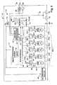
- the series of image frames for each camera assembly C1-C6 is shown schematically as IF1, IF2, IF3, IF4, IF5, IF6 in FIG. 7 .
- Each series of image frames IF1-IF6 comprises a sequence of individual image frames generated by the respective cameras C1-C6.
- the designation IF 1 for example, represents multiple successive images obtained from the camera C1.
- the image frames IF1-IF6 are in the form of respective digital signals representative of raw gray scale values generated by each of the camera assembly C1-C6.
- Digital signals 35 that make up the frames are coupled to a bus interface 42, where the signals are multiplexed by a multiplexer 43 and then communicated to a memory 44 in an organized fashion so that the processor knows which image representation belong to a given camera.
- the image processors 15 access the image frames IF1-IF6 from memory 44 and search for image frames that include an imaged target bar code 30'. If the imaged target bar code 30' is present and decodable in one or more image frames, the decoder 16 attempts to decode the imaged target bar code 30' using one or more of the image frames having the imaged target bar code 30' or a portion thereof. If no bar code is present, the image processors look for items such as the screw 230 shown in Figure 9 within the image.
- Each camera includes a charged coupled device (CCD), a complementary metal oxide semiconductor (CMOS), or other imaging pixel array, operating under the control of the imaging processing system 40.
- the sensor array comprises a two-dimensional (2D) CMOS array with a typical size of the pixel array being on the order of 752 x 480 pixels.
- the illumination-receiving pixels of the sensor array define a sensor array surface secured to a printed circuit board for stability.
- the sensor array surface is substantially perpendicular to an optical axis of the imaging lens assembly, that is, a z axis that is perpendicular to the sensor array surface would be substantially parallel to the optical axis of the focusing lens.
- the pixels of the sensor array surface are disposed in an orthogonal arrangement of rows and columns of pixels.
- the reader circuitry 11 includes imaging system 12, the memory 44 and a power supply 11a.
- the power supply 11a is electrically coupled to and provides power to the circuitry 11 of the reader.
- the reader 10 may include an illumination system 60 (shown schematically in FIG. 7 ) which provides illumination to illuminate the effective total field-of-view to facilitate obtaining an image 30' of a target bar code 30 that has sufficient resolution and clarity for decoding.
- An exemplary system uses light emitting diodes closely spaced from an associated charge coupled device for each of the cameras C1 - C6 that are selectively activated to emit light under control of the processors 15.
- the digital signals 35 are received by the bus interface 42 of the image processing system 40, which may include the multiplexer 43, operating under the control of an application specific integrated circuit (ASIC) 46, to serialize the image data contained in the digital signals 35.
- the digitized values of the digitized signal 35 are stored in the memory 44.
- the digital values GSV constitute a digitized version of the series of image frames IF1-IF6, which for each camera assembly C1-C6 and for each image frame is representative of the image projected by the imaging lens assembly onto the pixel array during an exposure period. If the field-of-view of the imaging lens assembly includes the target bar code 30, then a digital image 30' of the target bar code 30 is obtained.
- the decoding circuitry 14 performs a process 110 on selected image frames by getting an image 120 from memory and determining 122 if the image has a bar code. If so the processor 15 attempts to decode 124 any decodable image within the image frames, e.g., the imaged target bar code 30'. If the decoding is successful, decoded data 56, representative of the data/information coded in the target bar code 30 is then output 126 via a data output port 58 and/or displayed to a user of the reader 10 via a display 59.
- a speaker 34b and/or an indicator LED 34a is activated by the bar code reader circuitry 11 to indicate to the user that the target bar code 30 has been successfully read.
- a barcode reader 10 To acquire data from images of items that do not have bar codes with a barcode reader 10 requires a knowledge of the pixel per inch at a location having a fixed distance to the object or item that is imaged.
- a multiple camera reader has a window H upon which objects, such as a screw 230, being imaged can be positioned during imaging.
- One goal of use of the reader is to determine the pitch, length and type of screw based on length dimensions of the features of the screw.
- the reader can also distinguish, for example, between various head shapes (flat head versus rounded etc) by comparing the imaged shapes with a database of shapes stored in memory of the reader or stored in a host computer with which the reader communicates.
- the reader 10 looks at the object through the window H on which it rests so the distance from the imager or camera is known and measurements of the item are based on a fixed relation of pixels per inch of the sensor array that captures the image.
- FIG 10 Another way to use an imaging based bar code reader is to image the item simultaneously with a target such a grid 231 ( FIG 10 ) on a weighing scale 234.
- a scale could be incorporated into a reader 10 and the weighing surface would be part of the horizontal window H onto which products are placed.
- the grid has a specified known grid spacing between markings such as inches, centimeters etc.
- Such a system can be used with a handheld image reader 24 ( FIG 11 ) wherein the target is at or near the cash register or check out station so the item can be placed on the target grid 231 and the item and target are imaged simultaneously. No particular distance between the target grid 231 and reader is required. If no markings are present, however the spacing must be constant such as achieved by having the reader 24 mounted in the stand 25.
- the reader then uses a pre-calibrated pixel per dimension value to determine object features.
- the support surface 232 shown in Figure 10 can have a groove or be slightly concave ( FIG 10A ) to keep round items from rolling away and in the exemplary embodiment this surface is bound by an included border 233.
- a surface 232 on which the grid 231 is affixed is a weighing scale surface or platform that forms part of the scale 234 and which transmits weight signals back to the processor or processors 15 in the reader for use in identifying features of non-bar code carrying parts.
- the size of the object being imaged can be compared to reference marks on the grid. For example, if the marks are an inch apart, the processor can count pixels to see how many pixels appear between the marks, establishing a pixels per inch reference value. Such calibration would typically be done during manufacture of the reader.
- Pixels distances across various dimensions of the object being imaged are subsequently determined during use of the reader to measure those features of the object of concern.
- Different classes of objects are identified by different features.
- a generic class type (screw, bolt, nut etc) is entered 130 at a user input to the reader.
- the reader determines 132 a specific feature of the object based on knowledge conveyed by the generic class object. Alternately, a variety of different classes are stored in the reader and the reader processor 15 determines by means of pattern matching the image of the object what generic class the object falls into. Once all features of an item (possibly including its weight) have been determined the processor identifies 134 the item and optionally displays the information on a visual display.
- the distance to the window H is know and the number of pixels per inch can be programmed into the reader memory or calibrated into the reader by scanning a calibration target 240 during a calibration procedure at the factory. Reference marks are not visible in the same image as the object or item being measured after the calibration has been completed.
- reference marks 242 are designed to extend the visible camera field of view outside the borders of the clear window aperture such as the aperture defined by the window H. Calibration marks around the window or on a calibration target placed on the window allow the reader to determine pixels per inch anywhere on the window even if the window is tilted with respect to the camera.
- the number can be scanned and interpreted by the imager using an optical character recognition technology.
- optical character recognition can eliminate the need for manual data entry of such codes and instead allow the reader to determine the code and correlate the code with the product.
- the reader 10 is used in conjunction with a scale 234 that weighs items sitting on the horizontal window H.
- the scale can be used to confirm that the item has been correctly identified. For example, once a screw has been measured by the processors 15, and an identification has been tentatively made, the weight of the screw, as measured by the scale during the optical measurement process, is compared to a database of weights of various screws, nuts, washers, etc that are sold in a given store location. If the measured weight and the weight in the database match, it is highly likely that the identification is correct. Once an individual item has been identified, the scale count multiple items, if they are all placed on the scale by dividing the total weight by the unit weight determined for a single item. The customer can be charged for the correct number of screws without the clerk counting them.
- the scale can also help distinguish between washers of different thickness, which will have different weights. Different thicknesses will not be distinguishable by the processors. Weights will also help distinguish screws, nuts and washers made of different materials. Stores may sell both metal and plastic screws, nuts and washers.
- the color (if a color reader is used) or gray scale value (with a monochrome sensor) can also help distinguish different finishes or materials. If a hand held scanner is being used a scale can be placed below or near the reader where the items being identified are to be placed.
- the weight database can be automatically created when new items are added to the store's inventory by storing the measured weight when a scanner sees a new item. Weights of several items can be averaged formore accurate standard weight for each item.
- a dual window bar code reader includes the printed circuit board 22 having six imaging cameras thereon, where three cameras having a field-of-view extending from a generally horizontal window H are shown, namely C1, C2, and C3.
- Camera or imager C1 and its associated optics faces generally vertically upward toward an inclined folding mirror M1A substantially directly overhead at a left side of the horizontal window H.
- the folding mirror M1A faces another inclined narrow folding mirror M1B located at a right side of the horizontal window H.
- the folding mirror M1B faces still another inclined wide folding mirror M1C adjacent the mirror M1A.
- the folding mirror M1C faces out through the generally horizontal window H toward the right side of the dual window scanner such to form an imaging field-of-view 210 illustrated in FIG. 7 .
- a region of imaging coverage 220 resulting from the field-of-view projected from camera C1 is produced, substantially filling the scanning area illustrated on the horizontal window H in FIG. 8 .
- the field of view is adjusted to include the marking 242.
- the camera or imager C3 and its associated optics are symmetrical with respect to a center line of the reader to imager C1.
- Camera C3 faces generally vertically upward toward an incline folding mirror M3A substantially directly overhead at a right side of the horizontal window H.
- the folding mirror M3A faces another inclined narrow folding mirror M3B located at a left side of the horizontal window H.
- the folding mirror M3B faces still another inclined wide folding mirror M3C adjacent the mirror M3A.
- the folding mirror M3C faces out through the generally horizontal window H toward the left side of the dual window reader.
- Imager or camera C2 and its associated optics are located between imagers C1 and C3 and their associated optics.
- Imager C2 faces generally vertically upward toward an inclined folding mirror M2A substantially directly overhead generally centrally of the horizontal window H at one end thereof.
- the folding mirror M2A faces another inclined folding mirror M2B located at the opposite end of the horizontal window H.
- the folding mirror M2B faces out through the window H in an upward direction toward the vertical window V in the housing 20.
- the dual window reader has a camera or imager C4 and its associated optics faces generally vertically upward toward an incline folding mirror M4A substantially directly overhead at a left side of the vertical window V.
- the folding mirror M4A faces another inclined narrow folding mirror M4B located at a right side of the vertical window V.
- the folding mirror M4B faces still another inclined wide folding mirror M4C adjacent the mirror M4A.
- the folding mirror M4C faces out through the generally vertical window V toward the right side of the dual window reader.
- camera or imager C6 and its associated optics is mirror symmetrical to imager C4.
- Camera C6 faces generally vertically upward toward an incline folding mirror M6A substantially directly overhead at a right side of the vertical window V.
- the folding mirror M6A faces another inclined narrow folding mirror M6B located at a left side of the vertical window V.
- the folding mirror M6B faces still another inclined wide folding mirror M6C adjacent the mirror M6A.
- the folding mirror M6C faces out through the generally vertical window V toward the left side of the dual window reader.
- imager or camera C5 and its associated optics are located generally centrally between imagers C4 and C6 and their associated optics.
- Imager C5 faces generally vertically upward toward an inclined folding mirror M5A substantially directly overhead generally centrally of the vertical window V at one end thereof.
- the folding mirror M5A faces out through the window V in a downward direction toward the horizontal window H in the housing 20.
Landscapes
- Physics & Mathematics (AREA)
- Engineering & Computer Science (AREA)
- Electromagnetism (AREA)
- General Physics & Mathematics (AREA)
- Theoretical Computer Science (AREA)
- Health & Medical Sciences (AREA)
- General Health & Medical Sciences (AREA)
- Toxicology (AREA)
- Artificial Intelligence (AREA)
- Computer Vision & Pattern Recognition (AREA)
- Image Input (AREA)
Claims (15)
- Strichcodelesegerät zum Lesen von Strichcodes und zum Bestimmen eines Merkmals eines Zielobjekts (32), das nicht mit einem Strichcode versehen ist, wobei das Strichcodelesegerät Folgendes umfasst:ein Gehäuse (20) mit einem oder mehreren transparenten Fenstern (H, V), das einen Gehäuseinnenbereich definiert, wobei zum Abbilden eines Zielobjekts ein Zielobjekt in Bezug zu den transparenten Fenstern vorbeigezogen oder präsentiert wird,ein Beleuchtungssystem (60) mit einer oder mehreren Beleuchtungsquellen, das zum Bereitstellen von Beleuchtung zwecks Beleuchtens des Zielobjekts durch eines der transparenten Fenster in dem Gehäuseinnenbereich positioniert ist,eine Kamera (C1-C6) mit einem Bilderfassungssensorfeld zum Erfassen eines Bilds von dem Zielobjekt durch eines der transparenten Fenster, die in dem Gehäuseinnenbereich positioniert ist, undein Bildverarbeitungssystem (40) mit einem Prozessor (15) zum Interpretieren des Bilds von dem Zielobjekt, um zu bestimmen, ob ein Strichcode vorhanden ist, und zum Decodieren des Strichcodes in dem Bild vom Zielobjekt, wenn dieser vorhanden ist, und zum Identifizieren des Zielobjekts durch Bestimmen eines Merkmals des Zielobjekts aus dem von dem Bildgebungssystem erfassten Bild vom Zielobjekt, wenn dieser nicht vorhanden ist, und dadurch gekennzeichnet, dasszu dem Merkmal ein Längenmaß einer Eigenschaft des Zielobjekts gehört.
- Strichcodelesegerät nach Anspruch 1, bei dem das Gehäuse ein horizontales Fenster (H) aufweist, auf das das Zielobjekt für die Bildgebung platziert wird.
- Strichcodelesegerät nach Anspruch 1, das ferner eine Kalibrierungsskala umfasst, die an dem Gehäuse angebracht ist und gleichmäßig beabstandete Markierungen für die Bildgebung durch das Verarbeitungssystem zum Kalibrieren des Verarbeitungssystems aufweist.
- Strichcodelesegerät nach Anspruch 1, das zusätzlich ein Kalibrierungsobjekt umfasst, welches mit einer sichtbaren Kalibrierungskala für die Bildgebung durch die Kamera versehen ist, damit es für das Bildverarbeitungssystem möglich ist, Maße von Objektmerkmalen im Sichtfeld zu bestimmen.
- Strichcodelesegerät nach Anspruch 4, bei dem das Bildverarbeitungssystem den Bildelementabstand mit Abständen zwischen Markierungen an der sichtbaren Kalibrierungsskala korreliert.
- Strichcodelesegerät nach Anspruch 1, bei dem das Bildverarbeitungssystem ein Texterkennungsprogramm zum Interpretieren von Zeichen an dem nicht mit einem Strichcode versehenen Zielobjekt umfasst.
- Strichcodelesegerät nach Anspruch 1, das zusätzlich eine Waage (234) umfasst und bei dem zu einem Merkmal eines nicht mit einem Strichcode versehenen Gegenstands das Gewicht des Gegenstands gehört.
- Verfahren zum Identifizieren eines Zielobjekts, das Folgendes umfasst:Bereitstellen eines Gehäuses (20) mit einem oder mehreren transparenten Fenstern (H, V), die einen Bereich für das Bewegen und/ oder Positionieren eines Objekts definieren,Positionieren einer Kamera (C1-C6) in dem Gehäuse mit einem Sensorfeld zum Abbilden von Strichcodes an Objekten außerhalb des Gehäuses ,Beleuchten des Zielobjekts mit einer oder mehreren in dem Gehäuseinnenbereich positionierten Beleuchtungsquellen (60) durch eines der transparenten Fenster (H, V),Erfassen eines Bilds von dem Zielobjekt (32) durch eines der transparenten Fenster (H, V), während Licht vom Zielobjekt auf das Sensorfeld trifft, undInterpretieren des Bilds von dem Zielobjekt, um zu bestimmen, ob ein Strichcode vorhanden ist, und Decodieren des Strichcodes, wenn dieser vorhanden ist, und Identifizieren des Zielobjekts durch Bestimmen eines Merkmals des Zielobjekts aus dem Bild vom Zielobjekt, wenn dieser nicht vorhanden ist, und dadurch gekennzeichnet, dasszu dem Merkmal ein Längenmaß einer Eigenschaft des Zielobjekts gehört.
- Verfahren nach Anspruch 8, das zusätzlich das Erfassen eines Bilds von einem Kalibrierungsobjekt mit Markierungen, die über eine Fläche des Kalibrierungsobjekts hinweg gleichmäßig beabstandet sind, und das Kalibrieren des Sensorfelds umfasst, um eine Pixel/Länge-Eigenschaft des Lesegeräts zu bestimmen.
- Verfahren nach Anspruch 9, bei dem das Kalibrierungsobjekt auf zumindest einem Abschnitt eines der Fenster platziert und nach Erfassen des Bilds von dem Kalibrierungsobjekt entfernt wird.
- Verfahren nach Anspruch 9, bei dem das Abbilden des Kalibrierungsobjekts vor der Lieferung des Lesegeräts an einen Kunden erfolgt und eine Pixel/Länge-Eigenschaft in einem Speicher des Lesegeräts gespeichert wird.
- Verfahren nach Anspruch 8, das das Platzieren eines Zielobjekts in unmittelbarer Nähe eines Kalibrierungsobjekts mit gleichmäßigen Markierungen umfasst, um das Kalibrierungsobjekt und das Zielobjekt gleichzeitig abzubilden und dann das Merkmal mit Abständen zwischen Markierungen am Kalibrierungsobjekt zu korrelieren.
- Verfahren nach Anspruch 8, das das Bestimmen eines Gewichts eines nicht mit einem Strichcode versehenen Gegenstands umfasst.
- Verfahren nach Anspruch 13, bei dem das Gewicht eines Gegenstands zum Bestätigen einer visuellen Bestimmung eines weiteren Merkmals des Gegenstands auf der Grundlage eines Bilds von diesem Gegenstand benutzt wird.
- Verfahren nach Anspruch 13, bei dem mehrere gleiche Gegenstände auf einer Wiegefläche platziert werden und das Gewicht der mehreren gleichen Gegenstände zum Zählen der Gegenstände durch Dividieren eines Gesamtgewichts durch ein Stückgewicht der Gegenstände benutzt wird.
Applications Claiming Priority (2)
| Application Number | Priority Date | Filing Date | Title |
|---|---|---|---|
| US12/266,642 US8479996B2 (en) | 2008-11-07 | 2008-11-07 | Identification of non-barcoded products |
| PCT/US2009/061838 WO2010053723A1 (en) | 2008-11-07 | 2009-10-23 | Identification of non-barcoded products |
Publications (2)
| Publication Number | Publication Date |
|---|---|
| EP2347368A1 EP2347368A1 (de) | 2011-07-27 |
| EP2347368B1 true EP2347368B1 (de) | 2015-12-16 |
Family
ID=41470196
Family Applications (1)
| Application Number | Title | Priority Date | Filing Date |
|---|---|---|---|
| EP09748897.7A Active EP2347368B1 (de) | 2008-11-07 | 2009-10-23 | Identifikation von nicht mit strichcode versehenen produkten |
Country Status (3)
| Country | Link |
|---|---|
| US (1) | US8479996B2 (de) |
| EP (1) | EP2347368B1 (de) |
| WO (1) | WO2010053723A1 (de) |
Families Citing this family (77)
| Publication number | Priority date | Publication date | Assignee | Title |
|---|---|---|---|---|
| US8521448B1 (en) | 2009-10-21 | 2013-08-27 | The Boeing Company | Structural analysis using measurement of fastener parameters |
| US8683869B2 (en) * | 2008-09-04 | 2014-04-01 | The Boeing Company | Monitoring fastener preload |
| US8978967B2 (en) * | 2007-10-31 | 2015-03-17 | The Boeing Campany | Intelligent fastener system |
| US8810370B2 (en) | 2010-01-22 | 2014-08-19 | The Boeing Company | Wireless collection of fastener data |
| US8146821B2 (en) * | 2009-04-02 | 2012-04-03 | Symbol Technologies, Inc. | Auto-exposure for multi-imager barcode reader |
| US8255070B2 (en) * | 2009-10-07 | 2012-08-28 | The Boeing Company | Method and apparatus for establishing a camera focal length for installing fasteners |
| US8500017B2 (en) * | 2010-12-06 | 2013-08-06 | Ncr Corporation | Scanner and weigh scale with self-centering surface |
| US8939371B2 (en) | 2011-06-30 | 2015-01-27 | Symbol Technologies, Inc. | Individual exposure control over individually illuminated subfields of view split from an imager in a point-of-transaction workstation |
| JP5824340B2 (ja) * | 2011-11-18 | 2015-11-25 | 株式会社イシダ | 計量装置 |
| US8740086B2 (en) * | 2012-05-08 | 2014-06-03 | Symbol Technologies, Inc. | Apparatus for and method of reading indicia by using non-readily visible illumination light |
| USD709888S1 (en) * | 2012-07-02 | 2014-07-29 | Symbol Technologies, Inc. | Bi-optic imaging scanner module |
| US9286530B2 (en) | 2012-07-17 | 2016-03-15 | Cognex Corporation | Handheld apparatus for quantifying component features |
| US9519810B2 (en) | 2012-07-31 | 2016-12-13 | Datalogic ADC, Inc. | Calibration and self-test in automated data reading systems |
| US9245425B2 (en) * | 2013-02-14 | 2016-01-26 | Symbol Technologies, Llc | Produce lift apparatus |
| CN105593847A (zh) * | 2013-06-05 | 2016-05-18 | 弗瑞莎伯公司 | 用于智能购物的方法和设备 |
| USD723560S1 (en) | 2013-07-03 | 2015-03-03 | Hand Held Products, Inc. | Scanner |
| US9268979B2 (en) | 2013-09-09 | 2016-02-23 | Datalogic ADC, Inc. | System and method for aiming and calibrating a data reader |
| US10060785B2 (en) * | 2013-10-02 | 2018-08-28 | Datalogic Usa, Inc. | Systems and methods of alternate operation for a scanner-scale having an item overhang detection system |
| USD730901S1 (en) | 2014-06-24 | 2015-06-02 | Hand Held Products, Inc. | In-counter barcode scanner |
| US9396554B2 (en) | 2014-12-05 | 2016-07-19 | Symbol Technologies, Llc | Apparatus for and method of estimating dimensions of an object associated with a code in automatic response to reading the code |
| US10296918B1 (en) * | 2015-03-19 | 2019-05-21 | EMC IP Holding Company LLC | Providing risk assessments to compromised payment cards |
| US10352689B2 (en) | 2016-01-28 | 2019-07-16 | Symbol Technologies, Llc | Methods and systems for high precision locationing with depth values |
| US10145955B2 (en) | 2016-02-04 | 2018-12-04 | Symbol Technologies, Llc | Methods and systems for processing point-cloud data with a line scanner |
| JP6679344B2 (ja) * | 2016-02-29 | 2020-04-15 | 東芝テック株式会社 | 計量システム |
| US10721451B2 (en) | 2016-03-23 | 2020-07-21 | Symbol Technologies, Llc | Arrangement for, and method of, loading freight into a shipping container |
| US9805240B1 (en) | 2016-04-18 | 2017-10-31 | Symbol Technologies, Llc | Barcode scanning and dimensioning |
| JP6760780B2 (ja) * | 2016-07-04 | 2020-09-23 | 東芝テック株式会社 | 情報処理装置およびプログラム |
| US10776661B2 (en) | 2016-08-19 | 2020-09-15 | Symbol Technologies, Llc | Methods, systems and apparatus for segmenting and dimensioning objects |
| US11042161B2 (en) | 2016-11-16 | 2021-06-22 | Symbol Technologies, Llc | Navigation control method and apparatus in a mobile automation system |
| US10451405B2 (en) | 2016-11-22 | 2019-10-22 | Symbol Technologies, Llc | Dimensioning system for, and method of, dimensioning freight in motion along an unconstrained path in a venue |
| US10354411B2 (en) | 2016-12-20 | 2019-07-16 | Symbol Technologies, Llc | Methods, systems and apparatus for segmenting objects |
| WO2018204342A1 (en) | 2017-05-01 | 2018-11-08 | Symbol Technologies, Llc | Product status detection system |
| CN110603533A (zh) | 2017-05-01 | 2019-12-20 | 讯宝科技有限责任公司 | 用于对象状态检测的方法和装置 |
| US10591918B2 (en) | 2017-05-01 | 2020-03-17 | Symbol Technologies, Llc | Fixed segmented lattice planning for a mobile automation apparatus |
| US10663590B2 (en) | 2017-05-01 | 2020-05-26 | Symbol Technologies, Llc | Device and method for merging lidar data |
| US11449059B2 (en) | 2017-05-01 | 2022-09-20 | Symbol Technologies, Llc | Obstacle detection for a mobile automation apparatus |
| US10726273B2 (en) | 2017-05-01 | 2020-07-28 | Symbol Technologies, Llc | Method and apparatus for shelf feature and object placement detection from shelf images |
| US11367092B2 (en) | 2017-05-01 | 2022-06-21 | Symbol Technologies, Llc | Method and apparatus for extracting and processing price text from an image set |
| US10949798B2 (en) | 2017-05-01 | 2021-03-16 | Symbol Technologies, Llc | Multimodal localization and mapping for a mobile automation apparatus |
| WO2018201423A1 (en) | 2017-05-05 | 2018-11-08 | Symbol Technologies, Llc | Method and apparatus for detecting and interpreting price label text |
| TWI629450B (zh) * | 2017-08-01 | 2018-07-11 | 崑山科技大學 | Nail size measuring device |
| US10572763B2 (en) | 2017-09-07 | 2020-02-25 | Symbol Technologies, Llc | Method and apparatus for support surface edge detection |
| US10521914B2 (en) | 2017-09-07 | 2019-12-31 | Symbol Technologies, Llc | Multi-sensor object recognition system and method |
| US10331926B1 (en) * | 2017-12-18 | 2019-06-25 | Symbol Technologies, Llc | Bi-optic barcode reader |
| US10699511B2 (en) | 2018-03-14 | 2020-06-30 | Indie Llc | Systems and methods for performing automated fastener selection |
| US10823572B2 (en) | 2018-04-05 | 2020-11-03 | Symbol Technologies, Llc | Method, system and apparatus for generating navigational data |
| US10740911B2 (en) | 2018-04-05 | 2020-08-11 | Symbol Technologies, Llc | Method, system and apparatus for correcting translucency artifacts in data representing a support structure |
| US10832436B2 (en) | 2018-04-05 | 2020-11-10 | Symbol Technologies, Llc | Method, system and apparatus for recovering label positions |
| US11327504B2 (en) | 2018-04-05 | 2022-05-10 | Symbol Technologies, Llc | Method, system and apparatus for mobile automation apparatus localization |
| US10809078B2 (en) | 2018-04-05 | 2020-10-20 | Symbol Technologies, Llc | Method, system and apparatus for dynamic path generation |
| US11506483B2 (en) | 2018-10-05 | 2022-11-22 | Zebra Technologies Corporation | Method, system and apparatus for support structure depth determination |
| US11010920B2 (en) | 2018-10-05 | 2021-05-18 | Zebra Technologies Corporation | Method, system and apparatus for object detection in point clouds |
| US11003188B2 (en) | 2018-11-13 | 2021-05-11 | Zebra Technologies Corporation | Method, system and apparatus for obstacle handling in navigational path generation |
| US11090811B2 (en) | 2018-11-13 | 2021-08-17 | Zebra Technologies Corporation | Method and apparatus for labeling of support structures |
| US11079240B2 (en) | 2018-12-07 | 2021-08-03 | Zebra Technologies Corporation | Method, system and apparatus for adaptive particle filter localization |
| US11416000B2 (en) | 2018-12-07 | 2022-08-16 | Zebra Technologies Corporation | Method and apparatus for navigational ray tracing |
| US11100303B2 (en) | 2018-12-10 | 2021-08-24 | Zebra Technologies Corporation | Method, system and apparatus for auxiliary label detection and association |
| US11015938B2 (en) | 2018-12-12 | 2021-05-25 | Zebra Technologies Corporation | Method, system and apparatus for navigational assistance |
| US10731970B2 (en) | 2018-12-13 | 2020-08-04 | Zebra Technologies Corporation | Method, system and apparatus for support structure detection |
| CA3028708C (en) | 2018-12-28 | 2025-12-09 | Zebra Technologies Corporation | Method, system and apparatus for dynamic loop closure in mapping trajectories |
| US11662739B2 (en) | 2019-06-03 | 2023-05-30 | Zebra Technologies Corporation | Method, system and apparatus for adaptive ceiling-based localization |
| US11200677B2 (en) | 2019-06-03 | 2021-12-14 | Zebra Technologies Corporation | Method, system and apparatus for shelf edge detection |
| US11151743B2 (en) | 2019-06-03 | 2021-10-19 | Zebra Technologies Corporation | Method, system and apparatus for end of aisle detection |
| US11341663B2 (en) | 2019-06-03 | 2022-05-24 | Zebra Technologies Corporation | Method, system and apparatus for detecting support structure obstructions |
| US11080566B2 (en) | 2019-06-03 | 2021-08-03 | Zebra Technologies Corporation | Method, system and apparatus for gap detection in support structures with peg regions |
| US11960286B2 (en) | 2019-06-03 | 2024-04-16 | Zebra Technologies Corporation | Method, system and apparatus for dynamic task sequencing |
| US11402846B2 (en) | 2019-06-03 | 2022-08-02 | Zebra Technologies Corporation | Method, system and apparatus for mitigating data capture light leakage |
| US11507103B2 (en) | 2019-12-04 | 2022-11-22 | Zebra Technologies Corporation | Method, system and apparatus for localization-based historical obstacle handling |
| US11107238B2 (en) | 2019-12-13 | 2021-08-31 | Zebra Technologies Corporation | Method, system and apparatus for detecting item facings |
| US11822333B2 (en) | 2020-03-30 | 2023-11-21 | Zebra Technologies Corporation | Method, system and apparatus for data capture illumination control |
| US11450024B2 (en) | 2020-07-17 | 2022-09-20 | Zebra Technologies Corporation | Mixed depth object detection |
| US11593915B2 (en) | 2020-10-21 | 2023-02-28 | Zebra Technologies Corporation | Parallax-tolerant panoramic image generation |
| US11392891B2 (en) | 2020-11-03 | 2022-07-19 | Zebra Technologies Corporation | Item placement detection and optimization in material handling systems |
| US11847832B2 (en) | 2020-11-11 | 2023-12-19 | Zebra Technologies Corporation | Object classification for autonomous navigation systems |
| US11954882B2 (en) | 2021-06-17 | 2024-04-09 | Zebra Technologies Corporation | Feature-based georegistration for mobile computing devices |
| US11667474B1 (en) * | 2021-08-27 | 2023-06-06 | Amazon Technologies, Inc. | Increasing scan rate of parcels within material handling facility |
| CN117636546B (zh) * | 2023-11-30 | 2024-09-06 | 多点智联(北京)科技有限公司 | 自助收银台和购物车控制方法 |
Family Cites Families (67)
| Publication number | Priority date | Publication date | Assignee | Title |
|---|---|---|---|---|
| US3211046A (en) * | 1962-01-04 | 1965-10-12 | Texas Instruments Inc | Split image, high scanning rate optical system with constant aperture |
| US3947816A (en) * | 1974-07-01 | 1976-03-30 | International Business Machines Corporation | Omnidirectional optical scanning apparatus |
| US4613895A (en) * | 1977-03-24 | 1986-09-23 | Eastman Kodak Company | Color responsive imaging device employing wavelength dependent semiconductor optical absorption |
| US4794239A (en) * | 1987-10-13 | 1988-12-27 | Intermec Corporation | Multitrack bar code and associated decoding method |
| US5304786A (en) * | 1990-01-05 | 1994-04-19 | Symbol Technologies, Inc. | High density two-dimensional bar code symbol |
| US5059779A (en) * | 1989-06-16 | 1991-10-22 | Symbol Technologies, Inc. | Scan pattern generators for bar code symbol readers |
| US5124539A (en) * | 1989-06-16 | 1992-06-23 | Symbol Technologies, Inc. | Scan pattern generators for bar code symbol readers |
| US5200599A (en) * | 1989-06-16 | 1993-04-06 | Symbol Technologies, Inc | Symbol readers with changeable scan direction |
| US6330973B1 (en) * | 1989-10-30 | 2001-12-18 | Symbol Technologies, Inc. | Integrated code reading systems including tunnel scanners |
| US5058188A (en) * | 1989-11-10 | 1991-10-15 | Kabushiki Kaisha | Manual scan type image reader for correcting read image data to faithfully reproduce read image |
| US5206491A (en) * | 1990-03-02 | 1993-04-27 | Fujitsu Limited | Plural beam, plural window multi-direction bar code reading device |
| US5475207A (en) * | 1992-07-14 | 1995-12-12 | Spectra-Physics Scanning Systems, Inc. | Multiple plane scanning system for data reading applications |
| US7051922B2 (en) * | 1994-08-17 | 2006-05-30 | Metrologic Instruments, Inc. | Compact bioptical laser scanning system |
| US5559562A (en) * | 1994-11-01 | 1996-09-24 | Ferster; William | MPEG editor method and apparatus |
| US5703349A (en) * | 1995-06-26 | 1997-12-30 | Metanetics Corporation | Portable data collection device with two dimensional imaging assembly |
| US5691773A (en) * | 1995-09-12 | 1997-11-25 | Metanetics Corporation | Anti-hand-jittering dataform readers and methods |
| JP3441580B2 (ja) * | 1995-12-14 | 2003-09-02 | 富士通株式会社 | 読取装置 |
| US5717195A (en) * | 1996-03-05 | 1998-02-10 | Metanetics Corporation | Imaging based slot dataform reader |
| US5987428A (en) * | 1996-06-25 | 1999-11-16 | Ncr Corporation | Method and apparatus for checking out non-barcoded items at a checkout station |
| US6629642B1 (en) * | 1996-08-02 | 2003-10-07 | Symbol Technologies, Inc. | Data system and method for accessing a computer network using a collection of bar code symbols |
| US6141062A (en) * | 1998-06-01 | 2000-10-31 | Ati Technologies, Inc. | Method and apparatus for combining video streams |
| US6340114B1 (en) * | 1998-06-12 | 2002-01-22 | Symbol Technologies, Inc. | Imaging engine and method for code readers |
| US6336587B1 (en) * | 1998-10-19 | 2002-01-08 | Symbol Technologies, Inc. | Optical code reader for producing video displays and measuring physical parameters of objects |
| US6296186B1 (en) | 1998-11-19 | 2001-10-02 | Ncr Corporation | Produce recognition system including a produce shape collector |
| US6317152B1 (en) * | 1999-07-17 | 2001-11-13 | Esco Electronics Corporation | Digital video recording system |
| AUPQ212499A0 (en) * | 1999-08-10 | 1999-09-02 | Ajax Cooke Pty Ltd | Item recognition method and apparatus |
| US6392688B1 (en) * | 1999-10-04 | 2002-05-21 | Point Grey Research Inc. | High accuracy stereo vision camera system |
| US6538243B1 (en) * | 2000-01-04 | 2003-03-25 | Hewlett-Packard Company | Contact image sensor with light guide having least reflectivity near a light source |
| EP1261934A1 (de) | 2000-02-28 | 2002-12-04 | PSC Scanning, Inc. | Multiformat barkodeleser |
| US6924807B2 (en) * | 2000-03-23 | 2005-08-02 | Sony Computer Entertainment Inc. | Image processing apparatus and method |
| US6918540B2 (en) * | 2000-04-18 | 2005-07-19 | Metrologic Instruments, Inc. | Bioptical point-of-sale (pos) scanning system employing dual polygon-based laser scanning platforms disposed beneath horizontal and vertical scanning windows for 360° omni-directional bar code scanning |
| US6899272B2 (en) * | 2000-05-17 | 2005-05-31 | Symbol Technologies, Inc | Bioptics bar code reader |
| US7076097B2 (en) * | 2000-05-29 | 2006-07-11 | Sony Corporation | Image processing apparatus and method, communication apparatus, communication system and method, and recorded medium |
| US20020047047A1 (en) * | 2000-09-06 | 2002-04-25 | Paul Poloniewicz | Zero-footprint camera-based point-of-sale bar code presentation scanning system |
| US8042740B2 (en) * | 2000-11-24 | 2011-10-25 | Metrologic Instruments, Inc. | Method of reading bar code symbols on objects at a point-of-sale station by passing said objects through a complex of stationary coplanar illumination and imaging planes projected into a 3D imaging volume |
| US6502753B2 (en) * | 2001-02-26 | 2003-01-07 | Ncr Corporation | Compact dual aperture scanner |
| US7111787B2 (en) * | 2001-05-15 | 2006-09-26 | Hand Held Products, Inc. | Multimode image capturing and decoding optical reader |
| US6766954B2 (en) * | 2001-06-15 | 2004-07-27 | Symbol Technologies, Inc. | Omnidirectional linear sensor-based code reading engines |
| US20030078849A1 (en) * | 2001-10-23 | 2003-04-24 | Ncr Corporation | Self-checkout system having component video camera for produce purchase monitoring |
| GB2381687B (en) * | 2001-10-31 | 2005-08-24 | Hewlett Packard Co | Assisted reading method and apparatus |
| US7112812B2 (en) * | 2001-12-28 | 2006-09-26 | Applied Materials, Inc. | Optical measurement apparatus |
| US6783072B2 (en) * | 2002-02-01 | 2004-08-31 | Psc Scanning, Inc. | Combined data reader and electronic article surveillance (EAS) system |
| US20030213841A1 (en) * | 2002-05-14 | 2003-11-20 | Josephson Stanley M. | Method for verifying and authenticating initially named payee of negotiable instruments |
| US20040146211A1 (en) * | 2003-01-29 | 2004-07-29 | Knapp Verna E. | Encoder and method for encoding |
| US7248754B2 (en) * | 2003-05-05 | 2007-07-24 | International Business Machines Corporation | Apparatus and method for determining whether machine readable information on an item matches the item |
| JP4691900B2 (ja) * | 2004-05-12 | 2011-06-01 | セイコーエプソン株式会社 | 小切手処理方法、プログラムおよび小切手処理装置 |
| US8306128B2 (en) * | 2004-05-21 | 2012-11-06 | Texas Instruments Incorporated | Clocked output of multiple data streams from a common data port |
| US6974083B1 (en) * | 2004-07-23 | 2005-12-13 | Symbol Technologies, Inc. | Point-of-transaction workstation for electro-optically reading one-dimensional indicia, including image capture of two-dimensional targets |
| US7748631B2 (en) * | 2004-07-29 | 2010-07-06 | Symbol Technologies, Inc. | Point-of-transaction workstation for electro-optically reading one-dimensional and two-dimensional indicia by image capture |
| EP1626584A3 (de) * | 2004-08-11 | 2009-04-08 | Magna Donnelly GmbH & Co. KG | Fahrzeug mit Bildverarbeitungssystem und Verfahren zum Betrieb eines Bildverarbeitungssystems |
| US7293711B2 (en) * | 2004-08-30 | 2007-11-13 | Symbol Technologies, Inc. | Combination barcode imaging/decoding and real-time video capture system |
| WO2006060785A2 (en) * | 2004-12-01 | 2006-06-08 | Datalogic Scanning, Inc. | Triggering illumination for a data reader |
| US7204418B2 (en) * | 2004-12-08 | 2007-04-17 | Symbol Technologies, Inc. | Pulsed illumination in imaging reader |
| US7619527B2 (en) * | 2005-02-08 | 2009-11-17 | Datalogic Scanning, Inc. | Integrated data reader and electronic article surveillance (EAS) system |
| US7430682B2 (en) * | 2005-09-30 | 2008-09-30 | Symbol Technologies, Inc. | Processing image data from multiple sources |
| US7416119B1 (en) * | 2005-12-21 | 2008-08-26 | Ncr Corporation | Methods and apparatus for automatically determining and deducting weight of containers for products |
| US7475823B2 (en) * | 2006-05-26 | 2009-01-13 | Symbol Technologies, Inc. | Hand held bar code reader with improved image capture |
| US7724301B2 (en) * | 2006-11-27 | 2010-05-25 | Nokia Corporation | Determination of mechanical shutter exposure time |
| US7533819B2 (en) * | 2007-01-31 | 2009-05-19 | Symbol Technologies, Inc. | Dual camera assembly for an imaging-based bar code reader |
| US8794524B2 (en) * | 2007-05-31 | 2014-08-05 | Toshiba Global Commerce Solutions Holdings Corporation | Smart scanning system |
| US7757955B2 (en) * | 2008-04-30 | 2010-07-20 | Symbol Technologies, Inc. | Bar code reader having multiple cameras |
| US7780086B2 (en) | 2007-06-28 | 2010-08-24 | Symbol Technologies, Inc. | Imaging reader with plural solid-state imagers for electro-optically reading indicia |
| US8505824B2 (en) * | 2007-06-28 | 2013-08-13 | Symbol Technologies, Inc. | Bar code readers having multifold mirrors |
| US8662397B2 (en) * | 2007-09-27 | 2014-03-04 | Symbol Technologies, Inc. | Multiple camera imaging-based bar code reader |
| US20100102129A1 (en) * | 2008-10-29 | 2010-04-29 | Symbol Technologies, Inc. | Bar code reader with split field of view |
| US8079523B2 (en) * | 2008-12-15 | 2011-12-20 | Symbol Technologies, Inc. | Imaging of non-barcoded documents |
| CN102334128B (zh) * | 2008-12-26 | 2015-03-25 | 数据逻辑扫描公司 | 用于成像的系统和方法 |
-
2008
- 2008-11-07 US US12/266,642 patent/US8479996B2/en active Active
-
2009
- 2009-10-23 EP EP09748897.7A patent/EP2347368B1/de active Active
- 2009-10-23 WO PCT/US2009/061838 patent/WO2010053723A1/en not_active Ceased
Also Published As
| Publication number | Publication date |
|---|---|
| US20100116887A1 (en) | 2010-05-13 |
| EP2347368A1 (de) | 2011-07-27 |
| US8479996B2 (en) | 2013-07-09 |
| WO2010053723A1 (en) | 2010-05-14 |
Similar Documents
| Publication | Publication Date | Title |
|---|---|---|
| US8479996B2 (en) | Identification of non-barcoded products | |
| US7757955B2 (en) | Bar code reader having multiple cameras | |
| US20090020612A1 (en) | Imaging dual window scanner with presentation scanning | |
| US8118227B2 (en) | Multiple camera imaging-based bar code reader with optimized imaging field | |
| US8079523B2 (en) | Imaging of non-barcoded documents | |
| US11308297B2 (en) | Self-checkout system with scan gate and exception handling | |
| US8528820B2 (en) | Object identification using barcode reader | |
| US8662397B2 (en) | Multiple camera imaging-based bar code reader | |
| US20100001075A1 (en) | Multi-imaging scanner for reading images | |
| US8925815B2 (en) | Checkout system for and method of preventing a customer-operated accessory reader facing a bagging area from imaging targets on products passed through a clerk-operated workstation to the bagging area | |
| US8613393B2 (en) | Optical scanner with customer interface | |
| US20110073652A1 (en) | Method and apparatus for intelligently controlling illumination patterns projected from barcode readers | |
| EP2727046B1 (de) | Individuelle belichtungssteuerung über einzeln beleuchtete unterfelder einer geteilten ansicht einer bildgebungsvorrichtung in einem transaktionspunkt-arbeitsbereich | |
| AU2008272946A1 (en) | Imaging reader with plural solid-state imagers for electro-optically reading indicia | |
| US8678274B1 (en) | Point-of-transaction checkout system for and method of processing targets electro-optically readable by a clerk-operated workstation and by a customer-operated accessory reader | |
| US8727218B1 (en) | Symmetric customer side scanner for bioptic rear tower | |
| US9489554B2 (en) | Arrangement for and method of assessing efficiency of transactions involving products associated with electro-optically readable targets | |
| US9495564B2 (en) | Arrangement for and method of assessing a cause of poor electro-optical reading performance by displaying an image of a symbol that was poorly read | |
| EP3281159B1 (de) | Anordnung und verfahren zur bewertung der effizienz von transaktionen mit produkten, die mit elektro-optisch lesbaren zielen assoziiert sind |
Legal Events
| Date | Code | Title | Description |
|---|---|---|---|
| PUAI | Public reference made under article 153(3) epc to a published international application that has entered the european phase |
Free format text: ORIGINAL CODE: 0009012 |
|
| 17P | Request for examination filed |
Effective date: 20110505 |
|
| AK | Designated contracting states |
Kind code of ref document: A1 Designated state(s): AT BE BG CH CY CZ DE DK EE ES FI FR GB GR HR HU IE IS IT LI LT LU LV MC MK MT NL NO PL PT RO SE SI SK SM TR |
|
| AX | Request for extension of the european patent |
Extension state: AL BA RS |
|
| DAX | Request for extension of the european patent (deleted) | ||
| GRAP | Despatch of communication of intention to grant a patent |
Free format text: ORIGINAL CODE: EPIDOSNIGR1 |
|
| INTG | Intention to grant announced |
Effective date: 20150528 |
|
| RIN1 | Information on inventor provided before grant (corrected) |
Inventor name: SANDERS, ROBERT Inventor name: BARKAN, EDWARD D. |
|
| GRAS | Grant fee paid |
Free format text: ORIGINAL CODE: EPIDOSNIGR3 |
|
| GRAA | (expected) grant |
Free format text: ORIGINAL CODE: 0009210 |
|
| AK | Designated contracting states |
Kind code of ref document: B1 Designated state(s): AT BE BG CH CY CZ DE DK EE ES FI FR GB GR HR HU IE IS IT LI LT LU LV MC MK MT NL NO PL PT RO SE SI SK SM TR |
|
| REG | Reference to a national code |
Ref country code: GB Ref legal event code: FG4D |
|
| REG | Reference to a national code |
Ref country code: CH Ref legal event code: EP |
|
| REG | Reference to a national code |
Ref country code: IE Ref legal event code: FG4D |
|
| REG | Reference to a national code |
Ref country code: AT Ref legal event code: REF Ref document number: 765869 Country of ref document: AT Kind code of ref document: T Effective date: 20160115 |
|
| REG | Reference to a national code |
Ref country code: DE Ref legal event code: R096 Ref document number: 602009035259 Country of ref document: DE |
|
| REG | Reference to a national code |
Ref country code: DE Ref legal event code: R081 Ref document number: 602009035259 Country of ref document: DE Owner name: SYMBOL TECHNOLOGIES, LLC, HOLTSVILLE, US Free format text: FORMER OWNER: SYMBOL TECHNOLOGIES, INC., HOLTSVILLE, N.Y., US |
|
| RAP2 | Party data changed (patent owner data changed or rights of a patent transferred) |
Owner name: SYMBOL TECHNOLOGIES, LLC |
|
| REG | Reference to a national code |
Ref country code: NL Ref legal event code: MP Effective date: 20151216 |
|
| REG | Reference to a national code |
Ref country code: LT Ref legal event code: MG4D |
|
| PG25 | Lapsed in a contracting state [announced via postgrant information from national office to epo] |
Ref country code: LT Free format text: LAPSE BECAUSE OF FAILURE TO SUBMIT A TRANSLATION OF THE DESCRIPTION OR TO PAY THE FEE WITHIN THE PRESCRIBED TIME-LIMIT Effective date: 20151216 Ref country code: HR Free format text: LAPSE BECAUSE OF FAILURE TO SUBMIT A TRANSLATION OF THE DESCRIPTION OR TO PAY THE FEE WITHIN THE PRESCRIBED TIME-LIMIT Effective date: 20151216 Ref country code: NO Free format text: LAPSE BECAUSE OF FAILURE TO SUBMIT A TRANSLATION OF THE DESCRIPTION OR TO PAY THE FEE WITHIN THE PRESCRIBED TIME-LIMIT Effective date: 20160316 |
|
| REG | Reference to a national code |
Ref country code: AT Ref legal event code: MK05 Ref document number: 765869 Country of ref document: AT Kind code of ref document: T Effective date: 20151216 |
|
| PG25 | Lapsed in a contracting state [announced via postgrant information from national office to epo] |
Ref country code: NL Free format text: LAPSE BECAUSE OF FAILURE TO SUBMIT A TRANSLATION OF THE DESCRIPTION OR TO PAY THE FEE WITHIN THE PRESCRIBED TIME-LIMIT Effective date: 20151216 Ref country code: FI Free format text: LAPSE BECAUSE OF FAILURE TO SUBMIT A TRANSLATION OF THE DESCRIPTION OR TO PAY THE FEE WITHIN THE PRESCRIBED TIME-LIMIT Effective date: 20151216 Ref country code: LV Free format text: LAPSE BECAUSE OF FAILURE TO SUBMIT A TRANSLATION OF THE DESCRIPTION OR TO PAY THE FEE WITHIN THE PRESCRIBED TIME-LIMIT Effective date: 20151216 Ref country code: GR Free format text: LAPSE BECAUSE OF FAILURE TO SUBMIT A TRANSLATION OF THE DESCRIPTION OR TO PAY THE FEE WITHIN THE PRESCRIBED TIME-LIMIT Effective date: 20160317 Ref country code: SE Free format text: LAPSE BECAUSE OF FAILURE TO SUBMIT A TRANSLATION OF THE DESCRIPTION OR TO PAY THE FEE WITHIN THE PRESCRIBED TIME-LIMIT Effective date: 20151216 |
|
| PG25 | Lapsed in a contracting state [announced via postgrant information from national office to epo] |
Ref country code: IT Free format text: LAPSE BECAUSE OF FAILURE TO SUBMIT A TRANSLATION OF THE DESCRIPTION OR TO PAY THE FEE WITHIN THE PRESCRIBED TIME-LIMIT Effective date: 20151216 Ref country code: CZ Free format text: LAPSE BECAUSE OF FAILURE TO SUBMIT A TRANSLATION OF THE DESCRIPTION OR TO PAY THE FEE WITHIN THE PRESCRIBED TIME-LIMIT Effective date: 20151216 Ref country code: ES Free format text: LAPSE BECAUSE OF FAILURE TO SUBMIT A TRANSLATION OF THE DESCRIPTION OR TO PAY THE FEE WITHIN THE PRESCRIBED TIME-LIMIT Effective date: 20151216 |
|
| REG | Reference to a national code |
Ref country code: DE Ref legal event code: R082 Ref document number: 602009035259 Country of ref document: DE Representative=s name: LKGLOBAL | LORENZ & KOPF PARTG MBB PATENTANWAE, DE Ref country code: DE Ref legal event code: R082 Ref document number: 602009035259 Country of ref document: DE Representative=s name: KOPF, KORBINIAN, DIPL.-ING.UNIV., MA, DE Ref country code: DE Ref legal event code: R082 Ref document number: 602009035259 Country of ref document: DE Representative=s name: LKGLOBAL LORENZ UND KOPF PATENTANWALT, ATTORNE, DE |
|
| PG25 | Lapsed in a contracting state [announced via postgrant information from national office to epo] |
Ref country code: EE Free format text: LAPSE BECAUSE OF FAILURE TO SUBMIT A TRANSLATION OF THE DESCRIPTION OR TO PAY THE FEE WITHIN THE PRESCRIBED TIME-LIMIT Effective date: 20151216 Ref country code: PT Free format text: LAPSE BECAUSE OF FAILURE TO SUBMIT A TRANSLATION OF THE DESCRIPTION OR TO PAY THE FEE WITHIN THE PRESCRIBED TIME-LIMIT Effective date: 20160418 Ref country code: IS Free format text: LAPSE BECAUSE OF FAILURE TO SUBMIT A TRANSLATION OF THE DESCRIPTION OR TO PAY THE FEE WITHIN THE PRESCRIBED TIME-LIMIT Effective date: 20160416 Ref country code: AT Free format text: LAPSE BECAUSE OF FAILURE TO SUBMIT A TRANSLATION OF THE DESCRIPTION OR TO PAY THE FEE WITHIN THE PRESCRIBED TIME-LIMIT Effective date: 20151216 Ref country code: SM Free format text: LAPSE BECAUSE OF FAILURE TO SUBMIT A TRANSLATION OF THE DESCRIPTION OR TO PAY THE FEE WITHIN THE PRESCRIBED TIME-LIMIT Effective date: 20151216 Ref country code: RO Free format text: LAPSE BECAUSE OF FAILURE TO SUBMIT A TRANSLATION OF THE DESCRIPTION OR TO PAY THE FEE WITHIN THE PRESCRIBED TIME-LIMIT Effective date: 20151216 Ref country code: SK Free format text: LAPSE BECAUSE OF FAILURE TO SUBMIT A TRANSLATION OF THE DESCRIPTION OR TO PAY THE FEE WITHIN THE PRESCRIBED TIME-LIMIT Effective date: 20151216 |
|
| REG | Reference to a national code |
Ref country code: DE Ref legal event code: R097 Ref document number: 602009035259 Country of ref document: DE |
|
| REG | Reference to a national code |
Ref country code: FR Ref legal event code: PLFP Year of fee payment: 8 |
|
| PLBE | No opposition filed within time limit |
Free format text: ORIGINAL CODE: 0009261 |
|
| STAA | Information on the status of an ep patent application or granted ep patent |
Free format text: STATUS: NO OPPOSITION FILED WITHIN TIME LIMIT |
|
| PG25 | Lapsed in a contracting state [announced via postgrant information from national office to epo] |
Ref country code: PL Free format text: LAPSE BECAUSE OF FAILURE TO SUBMIT A TRANSLATION OF THE DESCRIPTION OR TO PAY THE FEE WITHIN THE PRESCRIBED TIME-LIMIT Effective date: 20151216 Ref country code: DK Free format text: LAPSE BECAUSE OF FAILURE TO SUBMIT A TRANSLATION OF THE DESCRIPTION OR TO PAY THE FEE WITHIN THE PRESCRIBED TIME-LIMIT Effective date: 20151216 |
|
| 26N | No opposition filed |
Effective date: 20160919 |
|
| PG25 | Lapsed in a contracting state [announced via postgrant information from national office to epo] |
Ref country code: BE Free format text: LAPSE BECAUSE OF FAILURE TO SUBMIT A TRANSLATION OF THE DESCRIPTION OR TO PAY THE FEE WITHIN THE PRESCRIBED TIME-LIMIT Effective date: 20151216 |
|
| PG25 | Lapsed in a contracting state [announced via postgrant information from national office to epo] |
Ref country code: SI Free format text: LAPSE BECAUSE OF FAILURE TO SUBMIT A TRANSLATION OF THE DESCRIPTION OR TO PAY THE FEE WITHIN THE PRESCRIBED TIME-LIMIT Effective date: 20151216 |
|
| REG | Reference to a national code |
Ref country code: CH Ref legal event code: PL |
|
| REG | Reference to a national code |
Ref country code: IE Ref legal event code: MM4A |
|
| PG25 | Lapsed in a contracting state [announced via postgrant information from national office to epo] |
Ref country code: LI Free format text: LAPSE BECAUSE OF NON-PAYMENT OF DUE FEES Effective date: 20161031 Ref country code: CH Free format text: LAPSE BECAUSE OF NON-PAYMENT OF DUE FEES Effective date: 20161031 |
|
| PG25 | Lapsed in a contracting state [announced via postgrant information from national office to epo] |
Ref country code: LU Free format text: LAPSE BECAUSE OF NON-PAYMENT OF DUE FEES Effective date: 20161023 |
|
| REG | Reference to a national code |
Ref country code: FR Ref legal event code: PLFP Year of fee payment: 9 |
|
| PG25 | Lapsed in a contracting state [announced via postgrant information from national office to epo] |
Ref country code: IE Free format text: LAPSE BECAUSE OF NON-PAYMENT OF DUE FEES Effective date: 20161023 |
|
| REG | Reference to a national code |
Ref country code: DE Ref legal event code: R082 Ref document number: 602009035259 Country of ref document: DE Representative=s name: LKGLOBAL | LORENZ & KOPF PARTG MBB PATENTANWAE, DE Ref country code: DE Ref legal event code: R082 Ref document number: 602009035259 Country of ref document: DE Representative=s name: LKGLOBAL LORENZ UND KOPF PATENTANWALT, ATTORNE, DE |
|
| PG25 | Lapsed in a contracting state [announced via postgrant information from national office to epo] |
Ref country code: HU Free format text: LAPSE BECAUSE OF FAILURE TO SUBMIT A TRANSLATION OF THE DESCRIPTION OR TO PAY THE FEE WITHIN THE PRESCRIBED TIME-LIMIT; INVALID AB INITIO Effective date: 20091023 Ref country code: CY Free format text: LAPSE BECAUSE OF FAILURE TO SUBMIT A TRANSLATION OF THE DESCRIPTION OR TO PAY THE FEE WITHIN THE PRESCRIBED TIME-LIMIT Effective date: 20151216 |
|
| PG25 | Lapsed in a contracting state [announced via postgrant information from national office to epo] |
Ref country code: MT Free format text: LAPSE BECAUSE OF NON-PAYMENT OF DUE FEES Effective date: 20161031 Ref country code: MC Free format text: LAPSE BECAUSE OF FAILURE TO SUBMIT A TRANSLATION OF THE DESCRIPTION OR TO PAY THE FEE WITHIN THE PRESCRIBED TIME-LIMIT Effective date: 20151216 Ref country code: TR Free format text: LAPSE BECAUSE OF FAILURE TO SUBMIT A TRANSLATION OF THE DESCRIPTION OR TO PAY THE FEE WITHIN THE PRESCRIBED TIME-LIMIT Effective date: 20151216 Ref country code: MK Free format text: LAPSE BECAUSE OF FAILURE TO SUBMIT A TRANSLATION OF THE DESCRIPTION OR TO PAY THE FEE WITHIN THE PRESCRIBED TIME-LIMIT Effective date: 20151216 |
|
| PG25 | Lapsed in a contracting state [announced via postgrant information from national office to epo] |
Ref country code: BG Free format text: LAPSE BECAUSE OF FAILURE TO SUBMIT A TRANSLATION OF THE DESCRIPTION OR TO PAY THE FEE WITHIN THE PRESCRIBED TIME-LIMIT Effective date: 20151216 |
|
| REG | Reference to a national code |
Ref country code: FR Ref legal event code: PLFP Year of fee payment: 10 |
|
| P01 | Opt-out of the competence of the unified patent court (upc) registered |
Effective date: 20230416 |
|
| PGFP | Annual fee paid to national office [announced via postgrant information from national office to epo] |
Ref country code: GB Payment date: 20250923 Year of fee payment: 17 |
|
| PGFP | Annual fee paid to national office [announced via postgrant information from national office to epo] |
Ref country code: FR Payment date: 20250923 Year of fee payment: 17 |
|
| PGFP | Annual fee paid to national office [announced via postgrant information from national office to epo] |
Ref country code: DE Payment date: 20250923 Year of fee payment: 17 |