EP2347239B1 - Portable strength test devices and methods for installed engineered material arresting systems - Google Patents
Portable strength test devices and methods for installed engineered material arresting systems Download PDFInfo
- Publication number
- EP2347239B1 EP2347239B1 EP09792932.7A EP09792932A EP2347239B1 EP 2347239 B1 EP2347239 B1 EP 2347239B1 EP 09792932 A EP09792932 A EP 09792932A EP 2347239 B1 EP2347239 B1 EP 2347239B1
- Authority
- EP
- European Patent Office
- Prior art keywords
- punch head
- testing device
- shaft
- portable
- emas
- Prior art date
- Legal status (The legal status is an assumption and is not a legal conclusion. Google has not performed a legal analysis and makes no representation as to the accuracy of the status listed.)
- Active
Links
- 238000012360 testing method Methods 0.000 title claims description 70
- 239000000463 material Substances 0.000 title claims description 39
- 238000000034 method Methods 0.000 title claims description 16
- 230000035515 penetration Effects 0.000 claims description 15
- 238000005070 sampling Methods 0.000 claims description 15
- 238000005259 measurement Methods 0.000 claims description 12
- 238000011065 in-situ storage Methods 0.000 claims description 4
- 238000004590 computer program Methods 0.000 claims description 3
- 239000002689 soil Substances 0.000 description 14
- 239000000523 sample Substances 0.000 description 9
- 238000013461 design Methods 0.000 description 7
- 238000010998 test method Methods 0.000 description 7
- 238000004364 calculation method Methods 0.000 description 2
- 238000009434 installation Methods 0.000 description 2
- 238000004519 manufacturing process Methods 0.000 description 2
- 241001520823 Zoysia Species 0.000 description 1
- 238000005299 abrasion Methods 0.000 description 1
- 238000007792 addition Methods 0.000 description 1
- 239000000956 alloy Substances 0.000 description 1
- 229910045601 alloy Inorganic materials 0.000 description 1
- 238000004458 analytical method Methods 0.000 description 1
- 230000008901 benefit Effects 0.000 description 1
- 239000000919 ceramic Substances 0.000 description 1
- 230000008859 change Effects 0.000 description 1
- 238000005056 compaction Methods 0.000 description 1
- 230000001010 compromised effect Effects 0.000 description 1
- 230000001276 controlling effect Effects 0.000 description 1
- 238000012217 deletion Methods 0.000 description 1
- 230000037430 deletion Effects 0.000 description 1
- 238000006073 displacement reaction Methods 0.000 description 1
- 230000007613 environmental effect Effects 0.000 description 1
- 238000007689 inspection Methods 0.000 description 1
- 238000012423 maintenance Methods 0.000 description 1
- 239000002184 metal Substances 0.000 description 1
- 239000000203 mixture Substances 0.000 description 1
- 238000012986 modification Methods 0.000 description 1
- 230000004048 modification Effects 0.000 description 1
- 229920000642 polymer Polymers 0.000 description 1
- 230000008569 process Effects 0.000 description 1
- 230000001105 regulatory effect Effects 0.000 description 1
- 230000000284 resting effect Effects 0.000 description 1
- 230000000087 stabilizing effect Effects 0.000 description 1
- 238000007619 statistical method Methods 0.000 description 1
- 239000002699 waste material Substances 0.000 description 1
Images
Classifications
-
- G—PHYSICS
- G01—MEASURING; TESTING
- G01N—INVESTIGATING OR ANALYSING MATERIALS BY DETERMINING THEIR CHEMICAL OR PHYSICAL PROPERTIES
- G01N3/00—Investigating strength properties of solid materials by application of mechanical stress
- G01N3/40—Investigating hardness or rebound hardness
- G01N3/42—Investigating hardness or rebound hardness by performing impressions under a steady load by indentors, e.g. sphere, pyramid
Definitions
- Embodiments of the present invention relate generally to a portable test apparatus and test methods for strength testing of low-strength materials, particularly on installed Engineered Material Arresting Systems, hereinafter referred to as EMAS or compressible vehicle arresting systems.
- EMAS Engineered Material Arresting Systems
- One example of an EMAS is described in, among others, U.S. Patent No. 5,885,025 entitled Vehicle Arresting Bed Systems.
- EMAS system or compressible vehicle arresting system comprises material placed at the end of a runway that will predictably and reliably crush (or otherwise deform) under the weight of an aircraft traveling off the end of the runway.
- the resistance provided by the low-strength material decelerates the aircraft and brings it to a stop within the confines of the overrun area.
- An object of the EMAS is to fail in a predictable, specified manner, thereby providing controlled, predictable resistive force as the vehicle deforms the EMAS system.
- An EMAS is thus generally compressible, deformable, crushable, or otherwise able to be compressed or deformed or crushed upon appropriate impact. EMAS is now part of the U.S.
- EMAS Engineered Materials Arresting Systems
- FAA Orders 5200.8 and 5200.9 FAA Orders 5200.8 and 5200.9.
- an EMAS material or compressible (or deformable) vehicle arresting system may be placed on or in a roadway or pedestrian walkway (or elsewhere), for example, for purposes of decelerating vehicles or objects other than aircraft.
- EMAS EMAS must meet all specified requirements in FAA Advisory Circular 150/5220-22A. Materials of certain strengths are selected to optimize EMAS performance for a specific fleet mix operating on a specific runway. The lifecycle cost calculations from FAA Order 5200.9 assume that EMAS may require replacement at a certain time. In order to determine that installed EMAS systems have maintained designed vehicle arresting capability, a field strength test device and test method needs to be developed to measure the strength of installed EMAS over time.
- This patent also defines the Compressive Gradient Strength (COS) standard, which has been used in-house to control material strength in production.
- COS Compressive Gradient Strength
- this patented in-house test method cannot be directly applied to field strength testing of installed EMAS systems at least because the test apparatus is not portable.
- This system tests an arresting material test section that is positioned on a bearing block. A load is then applied to the test section (using a hydraulic system that controls a shaft with a test probe head) at a relatively fast constant speed with force measurement occurring continuously or at small increments of displacement as the test probe head moves through the sample.
- U.S. Patent No. 2,117,986 (RIDENOUIR - 17 MAY 1938] is for soil-plasticity testing apparatus and discloses is for soil-plasticity testing apparatus and does not disclose recording measuring punch head speed, it only discloses to penetrate a sample of earth at an approximately correct rate of speed, for example, about 1 ⁇ 2 in. per second.
- JP 6319376 (IWASAKI ELECTRIC CO LTD. - 22 NOVEMBER 1994] is for apparatus for measuring strength of lawn grass. and specifies (resting) testing placed at an arbitrary place.
- embodiments of this invention provide a field strength test device and method that include hardware design, sample size determination, random sampling, and strength data interpretation.
- the described strength test devices and methods can be applied not only to existing EMAS systems, but also to new generations of EMAS, which may utilize other low-strength materials having similar arresting capabilities.
- Each type of material will have a unique tolerance band associated with a selected punch head size.
- Those tolerance bands will likely be pre-set by a regulatory authority or by an EMAS system manufacturer, and are set at the time of installation.
- the tolerance bands of the installed system should be appropriately tested at various intervals after installation using the devices and methods described herein in order to confirm that the materials are maintaining the desired and required strength over time.
- Embodiments of the invention described herein thus provide a strength test device and method that can be easily implemented in the field, on an existing and currently-installed EMAS (i.e. in situ).
- the desired portable test apparatus should take readings for resistive load and penetration depth.
- the measured resistive load can be converted into CGS.
- the penetration depth in the material can be measured using different types of distance measurement devices.
- embodiments of this invention provide a portable system and testing method for testing various features of currently-installed EMAS systems.
- a portable field testing device 10 includes a shaft 12, a punch head 20, and a measurement system 30.
- the shaft 12 may (but need not) be divided into two or more sections and assembled on-site.
- shaft 12 is provided in two parts, an upper shaft 14 and a lower shaft 16, that can be quickly assembled in the field but provide for easy transportation. It should be understood, however, that a single shaft or any number of shaft sections may be provided.
- the upper and lower shaft portions 14, 16, may be connected via a threaded connection 18.
- any number of appropriate connections may be used and are considered within the scope of this invention, such as snap fit connections, j lock/tab connections, dovetail connections, tapered connections, and so forth.
- the punch shaft 12 is at least about 25 inches long in order to cover desired maximum penetration depth.
- the shaft 12 should generally be at least about 5 inches long, but may be anywhere from 5 to 36 inches, and even longer if that eases use. In general, the length should be optimized for ease of operation to maintain a constant penetration speed.
- Device 10 also includes a punch head 20 at its lower portion.
- One type of punch head 20 has a flat lower surface 22 and a generally round diameter 24, as shown in FIG. 3 .
- the field testing device 10 may be based on a design with capabilities of taking measurements on resistive load and penetration depth. In other embodiments, the field testing device 10 may be built based on an existing soil penetrometer with a modified punch head and shaft.
- soil penetrometer 70 is shown in FIG. 4 .
- soil penetrometers generally have a cone-shaped or pointed punch head 72 that is designed to penetrate soil in order to measure various parameters.
- Soil penetrometers generally have a punch head for soil testing with either a 30° or 60° cone shape, as provided for by ASAE and ASTM standards. This is so that the pointed end of the soil penetrometer can penetrate soil easily.
- the field testing device 10 for testing an existing EMAS system has been designed with a punch head 20 preferably having a flat lower surface 22.
- Punch head 20 is also provided in a generally round or circular shape. The flat circular shape is selected so the punch head 20 overcomes the resistance primarily from the CGS strength of the material.
- the thickness 28 of the punch head 20 has been designed to minimize the friction resistance from the punch head 20.
- the cone-shaped head of a soil penetrometer would immediately penetrate the EMAS without testing an appropriate resistance at all.
- the material of the punch head should be chosen to resist wear due to abrasion by EMAS material.
- Non-limiting examples include any appropriate type of metal, polymer, or ceramic, or any combination or alloy thereof. It should be understood that punch head 20 may have a different effective surface and need not be perfectly flat and round.
- a suitable head size can be selected for testing certain strength material.
- Non-limiting examples of possible punch diameters range from about 0.5 to about 2.0 inches, although it should be understood that they may be larger or smaller, depending on the material and circumstances of the testing.
- the punch shaft 12 is shown in FIG. 1 as having a diameter 26 that is smaller than the diameter 24 of the punch head 20. This design helps eliminate the friction load from the shaft 12. It is also possible for the punch shaft 12 to be about the same size or equal to the diameter 24 of the punch head 20.
- the shaft 12 should also be sturdy enough to avoid buckling due to resistive load.
- the material of the shaft should be selected to resist wear for intensive use, examples of which may be the same as those provided above for the punch head 20.
- the device 10 also includes a handle 13 or some other type of gripping or stabilizing element at its upper portion.
- handle 13 may support a measurement system 30 for measuring the desired parameters that are being tested in the field (however, it should be understood that measurement system 30 may be located anywhere along shaft 12 as desired).
- the penetration depth of the punch head 20 can be measured using various distance or penetration depth sensors 32, such as ultrasonic and laser sensors. The selection of a distance sensor 32 will depend on required accuracy and environmental ruggedness. Because the material strength is sensitive to deformation rate, it is important to control penetration speed, which will significantly affect the resistive load measurement. The penetration speed can be calculated from penetration depth measurements.
- a speed indicator 34 can be used to assist in controlling the punch head speed.
- a resistive load sensor (not shown, but similar to the other sensors indicated on the handle) may also be provided.
- Determining a sample size is also important because oversized samples waste time and resources, while a sample size that is too small may be statistically insignificant and lead to inaccurate test results.
- the sample size can be determined primarily by desired level of precision, confidence level, and degree of variability in material strength. It is also important to use random sampling in order to reliably determine the mean strength of an EMAS system within a desired confidence interval.
- the location of samples for field strength testing can be determined using ASTM D 3665 on an effective EMAS arrestor area, which can be defined according to the EMAS design and maintenance standards.
- One embodiment of a method that may be used for field testing the strength of an installed EMAS system is to provide an appropriate field testing device, define a sample size to be taken, and identify sampling locations along the installed EMAS.
- the sampling locations (and specifically, random sampling locations) may be identified by a computer program in order to prevent operator error in location decisions.
- the operator should then drive the field testing device into each sampling location along the EMAS, record the resistive load, penetration depth, punch head speed. or any combination at each sampling location.
- the compressive gradient strength (CGS) of the material is calculated from the data obtained. This calculation may be done manually or by an appropriate computer program that receives and runs the data, and provides an output summary of the findings.
- CGS material strength
- the material strength, CGS can be calculated based on the associated punch head size. Being equivalent or similar to the tolerance bands defined in U.S. Patent No. 5,789,681 for in-house testing, field test tolerance bands should be developed for materials of certain strength and associated punch heads.
- the calculated material strength should be compared with a specific field test tolerance band. For example, once the CGS has been identified, it may be compared to defined CGS limits. The resultant material strength should then be presented as a confidence interval based on statistical analysis.
- Field strength testing should be conducted regularly to find the trend of strength change over time and to confirm that the installed system is maintaining its required strength. Integrated with other field inspection methods, the field strength test method described in this invention will help monitor the condition of installed EMAS systems.
Landscapes
- Physics & Mathematics (AREA)
- Health & Medical Sciences (AREA)
- Life Sciences & Earth Sciences (AREA)
- Chemical & Material Sciences (AREA)
- Analytical Chemistry (AREA)
- Biochemistry (AREA)
- General Health & Medical Sciences (AREA)
- General Physics & Mathematics (AREA)
- Immunology (AREA)
- Pathology (AREA)
- Investigating Strength Of Materials By Application Of Mechanical Stress (AREA)
Description
- This application claims the benefit of
U.S. Provisional Application Serial No. 61/099,937, filed September 25, 2008 - Embodiments of the present invention relate generally to a portable test apparatus and test methods for strength testing of low-strength materials, particularly on installed Engineered Material Arresting Systems, hereinafter referred to as EMAS or compressible vehicle arresting systems. One example of an EMAS is described in, among others,
U.S. Patent No. 5,885,025 entitled Vehicle Arresting Bed Systems. - One example of an EMAS system or compressible vehicle arresting system comprises material placed at the end of a runway that will predictably and reliably crush (or otherwise deform) under the weight of an aircraft traveling off the end of the runway. The resistance provided by the low-strength material decelerates the aircraft and brings it to a stop within the confines of the overrun area. An object of the EMAS is to fail in a predictable, specified manner, thereby providing controlled, predictable resistive force as the vehicle deforms the EMAS system. An EMAS is thus generally compressible, deformable, crushable, or otherwise able to be compressed or deformed or crushed upon appropriate impact. EMAS is now part of the U.S. airport design standards and is described in FAA Advisory Circular 150/5220-22A "Engineered Materials Arresting Systems (EMAS) for Aircraft Overruns" dated September 30, 2005. EMAS and Runway Safety Area planning are guided by FAA Orders 5200.8 and 5200.9. Alternatively, an EMAS material or compressible (or deformable) vehicle arresting system may be placed on or in a roadway or pedestrian walkway (or elsewhere), for example, for purposes of decelerating vehicles or objects other than aircraft.
- The design and manufacturing of EMAS must meet all specified requirements in FAA Advisory Circular 150/5220-22A. Materials of certain strengths are selected to optimize EMAS performance for a specific fleet mix operating on a specific runway. The lifecycle cost calculations from FAA Order 5200.9 assume that EMAS may require replacement at a certain time. In order to determine that installed EMAS systems have maintained designed vehicle arresting capability, a field strength test device and test method needs to be developed to measure the strength of installed EMAS over time.
-
WO 98/35217 U.S. Patent No. 5,789,681 ] describes one example of a test apparatus and test method for EMAS material. This patent also defines the Compressive Gradient Strength (COS) standard, which has been used in-house to control material strength in production. However, this patented in-house test method cannot be directly applied to field strength testing of installed EMAS systems at least because the test apparatus is not portable. This system tests an arresting material test section that is positioned on a bearing block. A load is then applied to the test section (using a hydraulic system that controls a shaft with a test probe head) at a relatively fast constant speed with force measurement occurring continuously or at small increments of displacement as the test probe head moves through the sample. However, if one wishes to test an EMAS system that has already been installed, removing one or more portions of the material from the system and transporting those portions back to the laboratory for testing is impractical and unreliable. Examples of potential problems are that the material may be cracked during removal of the test piece, or the entire system may be compromised from the removal of the testing piece, both causing problems with the testing process. Removal of a test piece in some cases conceivably could require that the entire EMAS bed be placed out of service, potentially precluding use of the associated runway for an extended period. -
U.S. Patent No. 2,117,986 (RIDENOUIR - 17 MAY 1938] is for soil-plasticity testing apparatus and discloses is for soil-plasticity testing apparatus and does not disclose recording measuring punch head speed, it only discloses to penetrate a sample of earth at an approximately correct rate of speed, for example, about ½ in. per second. -
JP 6319376 - There is a great need for field strength testing of installed EMAS systems. However, neither the patented in-house EMAS test apparatus nor the penetrometers for soil testing meet the specialized needs for EMAS field testing.
- A method and device in accordance with the present invention and embodiments thereof are set forth in the appended claims.
- Accordingly, embodiments of this invention provide a field strength test device and method that include hardware design, sample size determination, random sampling, and strength data interpretation. The described strength test devices and methods can be applied not only to existing EMAS systems, but also to new generations of EMAS, which may utilize other low-strength materials having similar arresting capabilities. Each type of material will have a unique tolerance band associated with a selected punch head size. Those tolerance bands will likely be pre-set by a regulatory authority or by an EMAS system manufacturer, and are set at the time of installation. However, the tolerance bands of the installed system should be appropriately tested at various intervals after installation using the devices and methods described herein in order to confirm that the materials are maintaining the desired and required strength over time.
- Embodiments of the invention described herein thus provide a strength test device and method that can be easily implemented in the field, on an existing and currently-installed EMAS (i.e. in situ). The desired portable test apparatus should take readings for resistive load and penetration depth. The measured resistive load can be converted into CGS. The penetration depth in the material can be measured using different types of distance measurement devices.
- Although some off-the-shelf soil penetrometers are capable of taking both resistive load and distance measurements, they cannot be directly applied to field strength testing of EMAS materials with their current designs. These penetrometers were designed mostly for soil compaction study. For example, the American Society of Agricultural Engineers (ASAE) and the American Society for Testing and Materials (ASTM) require the use of punch heads with cone shapes, which are particularly designed for soil testing, but they cannot be used for EMAS testing due to the unique properties of EMAS materials. Accordingly, embodiments of this invention provide a portable system and testing method for testing various features of currently-installed EMAS systems.
-
-
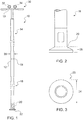
FIG. 1 shows a side plan view of one embodiment of a field testing device. -
FIG. 2 shows a close-up view of one end of the field testing device ofFIG. 1 . -
FIG. 3 shows a bottom plan view of one embodiment of a punch head of the field testing device ofFIG. 1 . -
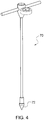
FIG. 4 shows an example of a prior art soil penetrometer prior to being modified according to various embodiments of this invention. -
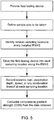
FIG. 5 shows a schematic of testing steps according to one testing method embodiment. - As shown in
FIG. 1 , one embodiment of a portablefield testing device 10 includes ashaft 12, apunch head 20, and ameasurement system 30. For increased portability, theshaft 12 may (but need not) be divided into two or more sections and assembled on-site. In the specific example shown inFIG. 1 ,shaft 12 is provided in two parts, anupper shaft 14 and alower shaft 16, that can be quickly assembled in the field but provide for easy transportation. It should be understood, however, that a single shaft or any number of shaft sections may be provided. As also shown in the specific embodiment ofFIG. 1 , the upper andlower shaft portions connection 18. Again, it should be understood that any number of appropriate connections may be used and are considered within the scope of this invention, such as snap fit connections, j lock/tab connections, dovetail connections, tapered connections, and so forth. - In a specific embodiment, the
punch shaft 12 is at least about 25 inches long in order to cover desired maximum penetration depth. Depending upon the type of materials to be tested, theshaft 12 should generally be at least about 5 inches long, but may be anywhere from 5 to 36 inches, and even longer if that eases use. In general, the length should be optimized for ease of operation to maintain a constant penetration speed. -
Device 10 also includes apunch head 20 at its lower portion. One type ofpunch head 20 has a flatlower surface 22 and a generallyround diameter 24, as shown inFIG. 3 . In one embodiment, thefield testing device 10 may be based on a design with capabilities of taking measurements on resistive load and penetration depth. In other embodiments, thefield testing device 10 may be built based on an existing soil penetrometer with a modified punch head and shaft. - One example of a
soil penetrometer 70 is shown inFIG. 4 . Although various options for such devices exist, soil penetrometers generally have a cone-shaped or pointedpunch head 72 that is designed to penetrate soil in order to measure various parameters. Soil penetrometers generally have a punch head for soil testing with either a 30° or 60° cone shape, as provided for by ASAE and ASTM standards. This is so that the pointed end of the soil penetrometer can penetrate soil easily. - Obviously, such a device would not be useful for testing the compressive gradient strength of an EMAS. The goal for such testing is not necessarily to penetrate the EMAS, but to determine its failure upon a certain applied load across a certain defined area. As such, the
field testing device 10 for testing an existing EMAS system has been designed with apunch head 20 preferably having a flatlower surface 22.Punch head 20 is also provided in a generally round or circular shape. The flat circular shape is selected so thepunch head 20 overcomes the resistance primarily from the CGS strength of the material. Thethickness 28 of thepunch head 20 has been designed to minimize the friction resistance from thepunch head 20. By contrast, the cone-shaped head of a soil penetrometer would immediately penetrate the EMAS without testing an appropriate resistance at all. The material of the punch head should be chosen to resist wear due to abrasion by EMAS material. Non-limiting examples include any appropriate type of metal, polymer, or ceramic, or any combination or alloy thereof. It should be understood thatpunch head 20 may have a different effective surface and need not be perfectly flat and round. A suitable head size can be selected for testing certain strength material. Non-limiting examples of possible punch diameters range from about 0.5 to about 2.0 inches, although it should be understood that they may be larger or smaller, depending on the material and circumstances of the testing. - The
punch shaft 12 is shown inFIG. 1 as having adiameter 26 that is smaller than thediameter 24 of thepunch head 20. This design helps eliminate the friction load from theshaft 12. It is also possible for thepunch shaft 12 to be about the same size or equal to thediameter 24 of thepunch head 20. Theshaft 12 should also be sturdy enough to avoid buckling due to resistive load. The material of the shaft should be selected to resist wear for intensive use, examples of which may be the same as those provided above for thepunch head 20. - The
device 10 also includes ahandle 13 or some other type of gripping or stabilizing element at its upper portion. As shown inFIG. 1 , handle 13 may support ameasurement system 30 for measuring the desired parameters that are being tested in the field (however, it should be understood thatmeasurement system 30 may be located anywhere alongshaft 12 as desired). In one embodiment, the penetration depth of thepunch head 20 can be measured using various distance orpenetration depth sensors 32, such as ultrasonic and laser sensors. The selection of adistance sensor 32 will depend on required accuracy and environmental ruggedness. Because the material strength is sensitive to deformation rate, it is important to control penetration speed, which will significantly affect the resistive load measurement. The penetration speed can be calculated from penetration depth measurements. Aspeed indicator 34 can be used to assist in controlling the punch head speed. A resistive load sensor (not shown, but similar to the other sensors indicated on the handle) may also be provided. - Determining a sample size is also important because oversized samples waste time and resources, while a sample size that is too small may be statistically insignificant and lead to inaccurate test results. The sample size can be determined primarily by desired level of precision, confidence level, and degree of variability in material strength. It is also important to use random sampling in order to reliably determine the mean strength of an EMAS system within a desired confidence interval. The location of samples for field strength testing can be determined using ASTM D 3665 on an effective EMAS arrestor area, which can be defined according to the EMAS design and maintenance standards.
- One embodiment of a method that may be used for field testing the strength of an installed EMAS system is to provide an appropriate field testing device, define a sample size to be taken, and identify sampling locations along the installed EMAS. The sampling locations (and specifically, random sampling locations) may be identified by a computer program in order to prevent operator error in location decisions. However, it is also possible for the operator to identify random locations along the EMAS, making sure to test at various heights and distances along the EMAS (e.g., not all samples should be located at the base of the EMAS and not all samples should be taken on one side or all on the other side on the EMAS, but along a good sampling of differing heights and distances).
- The operator should then drive the field testing device into each sampling location along the EMAS, record the resistive load, penetration depth, punch head speed. or any combination at each sampling location. Once all data has been obtained, the compressive gradient strength (CGS) of the material is calculated from the data obtained. This calculation may be done manually or by an appropriate computer program that receives and runs the data, and provides an output summary of the findings.
- Using the test procedure described above, resistive loads at randomly selected locations can be recorded as functions of penetration depth and later be downloaded onto a computer for analysis. The material strength, CGS, can be calculated based on the associated punch head size. Being equivalent or similar to the tolerance bands defined in
U.S. Patent No. 5,789,681 for in-house testing, field test tolerance bands should be developed for materials of certain strength and associated punch heads. The calculated material strength should be compared with a specific field test tolerance band. For example, once the CGS has been identified, it may be compared to defined CGS limits. The resultant material strength should then be presented as a confidence interval based on statistical analysis. - Field strength testing should be conducted regularly to find the trend of strength change over time and to confirm that the installed system is maintaining its required strength. Integrated with other field inspection methods, the field strength test method described in this invention will help monitor the condition of installed EMAS systems.
- Changes and modifications, additions and deletions may be made to the structures and methods recited above and shown in the drawings without departing from the scope of the invention and the following claims.
Claims (11)
- An in situ strength testing method, comprising:(a) providing a portable testing device (10) having a punch head (20);(b) identifying sampling locations;(c) driving the testing device (10) into each sampling location by an operator; and(d) measuring desired parameters at each sampling location,characterised in that the method is used to determine compressive gradient strength of an installed engineered material arresting system, the sampling locations are along the engineered material arresting system and the desired parameters comprise measured resistive load recorded as a function of penetration depth, and the punch head (20) speed.
- The method of claim 1, further comprising comparing the determined CGS to defined CGS limits.
- The method of any of the preceding claims, wherein the sampling locations identified are random.
- The method of claim 3, wherein the location of samples is determined using ASTM D 3665.
- The method of any of claims 1 to 4, wherein the sampling locations identified are identified by a computer program.
- A portable strength testing device (10) adapted to be driven into a sampling location by its operator, the device comprising:(a) a shaft (12) having a length and a diameter;(b) a punch head (20) at one end of the shaft having a flat surface (22); and(c) a measurement system (30);characterized in that:(d) the device (10) is adapted to determine compressive gradient strength of an installed engineered material arresting system, the measurement system (30) being configured to record resistive load as a function of penetration depth of the punch head (20) into the installed engineered material arresting system, and to measure the speed of the punch head.
- The portable in situ testing device of claim 6, wherein the measurement system (30) comprises a resistive load sensor, a penetration depth sensor (32) and a speed indicator (34).
- The portable testing device of claims 6 or 7, wherein the shaft (12) is provided in more than one section (14,16) for portability, and wherein the more than one sections are connectable to one another in use in situ.
- The portable testing device of any of claims 6-8, wherein punch head (20) has a flat lower surface (22) and a generally round diameter (24) and the shaft diameter (26) is smaller than or equal to the punch head diameter (24).
- The portable testing device of any of claims 6-9, wherein the length of the shaft (10) is from about 12.5 cm (5 inches) to about 90 cm (36 inches).
- The method of any of claims 1 to 5, wherein the portable testing device is the device recited by any of claims 6 to 10.
Applications Claiming Priority (2)
| Application Number | Priority Date | Filing Date | Title |
|---|---|---|---|
| US9993708P | 2008-09-25 | 2008-09-25 | |
| PCT/US2009/058167 WO2010036769A1 (en) | 2008-09-25 | 2009-09-24 | Field strength test devices and methods for installed engineered material arresting systems |
Publications (2)
| Publication Number | Publication Date |
|---|---|
| EP2347239A1 EP2347239A1 (en) | 2011-07-27 |
| EP2347239B1 true EP2347239B1 (en) | 2018-12-05 |
Family
ID=41490409
Family Applications (1)
| Application Number | Title | Priority Date | Filing Date |
|---|---|---|---|
| EP09792932.7A Active EP2347239B1 (en) | 2008-09-25 | 2009-09-24 | Portable strength test devices and methods for installed engineered material arresting systems |
Country Status (10)
| Country | Link |
|---|---|
| US (1) | US8479592B2 (en) |
| EP (1) | EP2347239B1 (en) |
| JP (1) | JP5714493B2 (en) |
| CN (1) | CN102216753A (en) |
| AU (1) | AU2009296623B2 (en) |
| BR (1) | BRPI0919082A2 (en) |
| CA (1) | CA2738373C (en) |
| ES (1) | ES2713273T3 (en) |
| MX (1) | MX2011003240A (en) |
| WO (1) | WO2010036769A1 (en) |
Families Citing this family (4)
| Publication number | Priority date | Publication date | Assignee | Title |
|---|---|---|---|---|
| US8656759B2 (en) * | 2010-03-18 | 2014-02-25 | Innoquest, Inc. | Handheld penetrating consistometer |
| US8797191B2 (en) | 2012-07-13 | 2014-08-05 | Honeywell International Inc. | Systems and methods for displaying runway information |
| GB201315687D0 (en) * | 2013-09-03 | 2013-10-16 | Dotocean Bvba | Sediment gaughing rod, stadia rod or sounding rod and handheld density profiler |
| CN108593538B (en) * | 2018-04-16 | 2023-11-21 | 中国民航科学技术研究院 | Large-span electronic testing machine for detecting physical performance of EMAS unit |
Family Cites Families (13)
| Publication number | Priority date | Publication date | Assignee | Title |
|---|---|---|---|---|
| US2117986A (en) | 1935-03-11 | 1938-05-17 | Wilkening Mfg Co | Piston ring construction |
| US2117985A (en) * | 1936-07-25 | 1938-05-17 | Ralph Roscoe Proctor | Soil-plasticity testing apparatus |
| JP2754315B2 (en) | 1993-05-13 | 1998-05-20 | 岩崎電気株式会社 | Turfgrass strength measuring device |
| JPH0815113A (en) * | 1994-06-27 | 1996-01-19 | Michio Arai | Hardness measuring apparatus for soil |
| JP3027598U (en) * | 1995-11-22 | 1996-08-13 | 建設省近畿地方建設局長 | Ground support force measuring device |
| JP3329676B2 (en) * | 1996-12-27 | 2002-09-30 | 飛島建設株式会社 | Method for estimating the strength of hardened concrete |
| US5789681A (en) | 1997-02-07 | 1998-08-04 | Datron Inc. | Arresting material test apparatus and methods |
| US5885025A (en) * | 1997-02-07 | 1999-03-23 | Datron Inc. | Vehicle arresting bed systems |
| US5902068A (en) * | 1997-02-07 | 1999-05-11 | Datron, Inc. | Vehicle arresting unit fabrication methods |
| US6726400B1 (en) * | 1997-02-07 | 2004-04-27 | Engineered Arresting Systems Corporation | Vehicle arresting bed systems |
| JP3602375B2 (en) * | 1999-07-07 | 2004-12-15 | 日本碍子株式会社 | Dehydration cake hardness meter and hardness measurement method using the same |
| CN1273816C (en) * | 2004-01-06 | 2006-09-06 | 武汉大学 | Portable full digital direct testing universal hardness meter |
| CN2700866Y (en) * | 2004-06-07 | 2005-05-18 | 天地科技股份有限公司 | Portable rock strength detection apparatus |
-
2009
- 2009-09-24 US US12/566,206 patent/US8479592B2/en active Active
- 2009-09-24 EP EP09792932.7A patent/EP2347239B1/en active Active
- 2009-09-24 BR BRPI0919082A patent/BRPI0919082A2/en not_active IP Right Cessation
- 2009-09-24 WO PCT/US2009/058167 patent/WO2010036769A1/en active Application Filing
- 2009-09-24 MX MX2011003240A patent/MX2011003240A/en active IP Right Grant
- 2009-09-24 ES ES09792932T patent/ES2713273T3/en active Active
- 2009-09-24 CN CN2009801461271A patent/CN102216753A/en active Pending
- 2009-09-24 CA CA2738373A patent/CA2738373C/en not_active Expired - Fee Related
- 2009-09-24 JP JP2011529212A patent/JP5714493B2/en active Active
- 2009-09-24 AU AU2009296623A patent/AU2009296623B2/en not_active Ceased
Non-Patent Citations (1)
| Title |
|---|
| None * |
Also Published As
| Publication number | Publication date |
|---|---|
| MX2011003240A (en) | 2011-06-17 |
| US20100071474A1 (en) | 2010-03-25 |
| JP5714493B2 (en) | 2015-05-07 |
| JP2012503778A (en) | 2012-02-09 |
| CA2738373C (en) | 2016-12-13 |
| CA2738373A1 (en) | 2010-04-01 |
| ES2713273T3 (en) | 2019-05-20 |
| US8479592B2 (en) | 2013-07-09 |
| AU2009296623B2 (en) | 2014-11-27 |
| AU2009296623A1 (en) | 2010-04-01 |
| BRPI0919082A2 (en) | 2015-12-15 |
| WO2010036769A1 (en) | 2010-04-01 |
| EP2347239A1 (en) | 2011-07-27 |
| CN102216753A (en) | 2011-10-12 |
Similar Documents
| Publication | Publication Date | Title |
|---|---|---|
| KR200485051Y1 (en) | Apparatus for measuring soil compaction | |
| EP2347239B1 (en) | Portable strength test devices and methods for installed engineered material arresting systems | |
| US8826738B2 (en) | Method and apparatus for measuring the structural integrity of a safe-life aircraft component | |
| US20160377518A1 (en) | An indentation device, instrumented measurement system, and a method for determining the mechanical properties of materials by the indentation method | |
| US8621903B2 (en) | Continuous or instrumented indentation device with convex bearing surface and use thereof, particularly for metal sheet indentation | |
| RU2469261C1 (en) | Method for determining complex strain and stress state of structure under static loads and dynamic stress | |
| EP3164637B1 (en) | Monitoring the structural health of columns | |
| WO2013158981A1 (en) | Method for non-destructive condition assessment and structural monitoring of concrete railroad ties in track | |
| EP3165896A1 (en) | Device and method for a non-destructive measurement of mechanical properties | |
| RU2192006C2 (en) | Method and apparatus for determining physicomechanical properties of ground layer preferably of low and average density | |
| US20110115639A1 (en) | Integrity monitored concrete pilings | |
| EP1116018A1 (en) | Measuring the energy absorbing capacity of a substrate | |
| CN112177064B (en) | Shear box device for simulating foundation pit wall soil interface | |
| EP3561614B1 (en) | Process for training a self-learning machine in a defect monitoring system | |
| Neves et al. | Uncertainty evaluation of deflection measurements from FWD tests on road pavements | |
| JP2021161652A (en) | Automatic penetration testing machine | |
| Griffin et al. | Evaluation of in situ characterization techniques for pavement applications of portland cement-stabilized soil | |
| Broutin et al. | Release of the French Technical Guidance for Flexible Airfield Pavement Assessment Using HWD | |
| Francois et al. | A proposed approach for processing and analyzing strain data collected in full-scale accelerated pavement testing | |
| Kalinowski et al. | The laboratory station for tyres grip testing on different surfaces | |
| Almeida Jr et al. | Brazilian bridges life cycle assessment using deterioration models | |
| Karmanov et al. | Analysis of modern monitoring methods of equipment at petrochemical plants in the process of operation | |
| ZlRINSKY | An ultrasonic technique to monitor fatigue damage in aircraft structures. | |
| PL212628B1 (en) | Method for diagnosis and/or monitoring of technical condition of reinforced concrete and prestressed concrete structures and a system for diagnosing the condition of reinforced concrete and prestressed concrete structures | |
| CN109253934A (en) | The in-situ check and test method of roof color steel plate safety |
Legal Events
| Date | Code | Title | Description |
|---|---|---|---|
| PUAI | Public reference made under article 153(3) epc to a published international application that has entered the european phase |
Free format text: ORIGINAL CODE: 0009012 |
|
| 17P | Request for examination filed |
Effective date: 20110419 |
|
| AK | Designated contracting states |
Kind code of ref document: A1 Designated state(s): AT BE BG CH CY CZ DE DK EE ES FI FR GB GR HR HU IE IS IT LI LT LU LV MC MK MT NL NO PL PT RO SE SI SK SM TR |
|
| AX | Request for extension of the european patent |
Extension state: AL BA RS |
|
| DAX | Request for extension of the european patent (deleted) | ||
| STAA | Information on the status of an ep patent application or granted ep patent |
Free format text: STATUS: EXAMINATION IS IN PROGRESS |
|
| 17Q | First examination report despatched |
Effective date: 20171117 |
|
| GRAP | Despatch of communication of intention to grant a patent |
Free format text: ORIGINAL CODE: EPIDOSNIGR1 |
|
| STAA | Information on the status of an ep patent application or granted ep patent |
Free format text: STATUS: GRANT OF PATENT IS INTENDED |
|
| INTG | Intention to grant announced |
Effective date: 20180702 |
|
| GRAS | Grant fee paid |
Free format text: ORIGINAL CODE: EPIDOSNIGR3 |
|
| GRAA | (expected) grant |
Free format text: ORIGINAL CODE: 0009210 |
|
| GRAA | (expected) grant |
Free format text: ORIGINAL CODE: 0009210 |
|
| STAA | Information on the status of an ep patent application or granted ep patent |
Free format text: STATUS: THE PATENT HAS BEEN GRANTED |
|
| AK | Designated contracting states |
Kind code of ref document: B1 Designated state(s): AT BE BG CH CY CZ DE DK EE ES FI FR GB GR HR HU IE IS IT LI LT LU LV MC MK MT NL NO PL PT RO SE SI SK SM TR |
|
| REG | Reference to a national code |
Ref country code: GB Ref legal event code: FG4D |
|
| REG | Reference to a national code |
Ref country code: CH Ref legal event code: EP |
|
| REG | Reference to a national code |
Ref country code: AT Ref legal event code: REF Ref document number: 1073675 Country of ref document: AT Kind code of ref document: T Effective date: 20181215 |
|
| REG | Reference to a national code |
Ref country code: IE Ref legal event code: FG4D |
|
| REG | Reference to a national code |
Ref country code: DE Ref legal event code: R096 Ref document number: 602009056071 Country of ref document: DE |
|
| REG | Reference to a national code |
Ref country code: CH Ref legal event code: NV Representative=s name: R.A. EGLI AND CO, PATENTANWAELTE, CH |
|
| REG | Reference to a national code |
Ref country code: SE Ref legal event code: TRGR |
|
| REG | Reference to a national code |
Ref country code: NL Ref legal event code: MP Effective date: 20181205 |
|
| REG | Reference to a national code |
Ref country code: AT Ref legal event code: MK05 Ref document number: 1073675 Country of ref document: AT Kind code of ref document: T Effective date: 20181205 Ref country code: NO Ref legal event code: T2 Effective date: 20181205 |
|
| REG | Reference to a national code |
Ref country code: LT Ref legal event code: MG4D |
|
| PG25 | Lapsed in a contracting state [announced via postgrant information from national office to epo] |
Ref country code: FI Free format text: LAPSE BECAUSE OF FAILURE TO SUBMIT A TRANSLATION OF THE DESCRIPTION OR TO PAY THE FEE WITHIN THE PRESCRIBED TIME-LIMIT Effective date: 20181205 Ref country code: LV Free format text: LAPSE BECAUSE OF FAILURE TO SUBMIT A TRANSLATION OF THE DESCRIPTION OR TO PAY THE FEE WITHIN THE PRESCRIBED TIME-LIMIT Effective date: 20181205 Ref country code: LT Free format text: LAPSE BECAUSE OF FAILURE TO SUBMIT A TRANSLATION OF THE DESCRIPTION OR TO PAY THE FEE WITHIN THE PRESCRIBED TIME-LIMIT Effective date: 20181205 Ref country code: HR Free format text: LAPSE BECAUSE OF FAILURE TO SUBMIT A TRANSLATION OF THE DESCRIPTION OR TO PAY THE FEE WITHIN THE PRESCRIBED TIME-LIMIT Effective date: 20181205 Ref country code: BG Free format text: LAPSE BECAUSE OF FAILURE TO SUBMIT A TRANSLATION OF THE DESCRIPTION OR TO PAY THE FEE WITHIN THE PRESCRIBED TIME-LIMIT Effective date: 20190305 Ref country code: AT Free format text: LAPSE BECAUSE OF FAILURE TO SUBMIT A TRANSLATION OF THE DESCRIPTION OR TO PAY THE FEE WITHIN THE PRESCRIBED TIME-LIMIT Effective date: 20181205 |
|
| REG | Reference to a national code |
Ref country code: ES Ref legal event code: FG2A Ref document number: 2713273 Country of ref document: ES Kind code of ref document: T3 Effective date: 20190520 |
|
| PG25 | Lapsed in a contracting state [announced via postgrant information from national office to epo] |
Ref country code: GR Free format text: LAPSE BECAUSE OF FAILURE TO SUBMIT A TRANSLATION OF THE DESCRIPTION OR TO PAY THE FEE WITHIN THE PRESCRIBED TIME-LIMIT Effective date: 20190306 |
|
| PG25 | Lapsed in a contracting state [announced via postgrant information from national office to epo] |
Ref country code: NL Free format text: LAPSE BECAUSE OF FAILURE TO SUBMIT A TRANSLATION OF THE DESCRIPTION OR TO PAY THE FEE WITHIN THE PRESCRIBED TIME-LIMIT Effective date: 20181205 |
|
| PG25 | Lapsed in a contracting state [announced via postgrant information from national office to epo] |
Ref country code: PT Free format text: LAPSE BECAUSE OF FAILURE TO SUBMIT A TRANSLATION OF THE DESCRIPTION OR TO PAY THE FEE WITHIN THE PRESCRIBED TIME-LIMIT Effective date: 20190405 Ref country code: CZ Free format text: LAPSE BECAUSE OF FAILURE TO SUBMIT A TRANSLATION OF THE DESCRIPTION OR TO PAY THE FEE WITHIN THE PRESCRIBED TIME-LIMIT Effective date: 20181205 Ref country code: PL Free format text: LAPSE BECAUSE OF FAILURE TO SUBMIT A TRANSLATION OF THE DESCRIPTION OR TO PAY THE FEE WITHIN THE PRESCRIBED TIME-LIMIT Effective date: 20181205 |
|
| PG25 | Lapsed in a contracting state [announced via postgrant information from national office to epo] |
Ref country code: SM Free format text: LAPSE BECAUSE OF FAILURE TO SUBMIT A TRANSLATION OF THE DESCRIPTION OR TO PAY THE FEE WITHIN THE PRESCRIBED TIME-LIMIT Effective date: 20181205 Ref country code: EE Free format text: LAPSE BECAUSE OF FAILURE TO SUBMIT A TRANSLATION OF THE DESCRIPTION OR TO PAY THE FEE WITHIN THE PRESCRIBED TIME-LIMIT Effective date: 20181205 Ref country code: SK Free format text: LAPSE BECAUSE OF FAILURE TO SUBMIT A TRANSLATION OF THE DESCRIPTION OR TO PAY THE FEE WITHIN THE PRESCRIBED TIME-LIMIT Effective date: 20181205 Ref country code: RO Free format text: LAPSE BECAUSE OF FAILURE TO SUBMIT A TRANSLATION OF THE DESCRIPTION OR TO PAY THE FEE WITHIN THE PRESCRIBED TIME-LIMIT Effective date: 20181205 Ref country code: IS Free format text: LAPSE BECAUSE OF FAILURE TO SUBMIT A TRANSLATION OF THE DESCRIPTION OR TO PAY THE FEE WITHIN THE PRESCRIBED TIME-LIMIT Effective date: 20190405 |
|
| REG | Reference to a national code |
Ref country code: DE Ref legal event code: R097 Ref document number: 602009056071 Country of ref document: DE |
|
| PLBE | No opposition filed within time limit |
Free format text: ORIGINAL CODE: 0009261 |
|
| STAA | Information on the status of an ep patent application or granted ep patent |
Free format text: STATUS: NO OPPOSITION FILED WITHIN TIME LIMIT |
|
| PG25 | Lapsed in a contracting state [announced via postgrant information from national office to epo] |
Ref country code: SI Free format text: LAPSE BECAUSE OF FAILURE TO SUBMIT A TRANSLATION OF THE DESCRIPTION OR TO PAY THE FEE WITHIN THE PRESCRIBED TIME-LIMIT Effective date: 20181205 Ref country code: DK Free format text: LAPSE BECAUSE OF FAILURE TO SUBMIT A TRANSLATION OF THE DESCRIPTION OR TO PAY THE FEE WITHIN THE PRESCRIBED TIME-LIMIT Effective date: 20181205 |
|
| 26N | No opposition filed |
Effective date: 20190906 |
|
| PG25 | Lapsed in a contracting state [announced via postgrant information from national office to epo] |
Ref country code: TR Free format text: LAPSE BECAUSE OF FAILURE TO SUBMIT A TRANSLATION OF THE DESCRIPTION OR TO PAY THE FEE WITHIN THE PRESCRIBED TIME-LIMIT Effective date: 20181205 |
|
| REG | Reference to a national code |
Ref country code: ES Ref legal event code: PC2A Owner name: RUNWAY SAFE IPR AB Effective date: 20200330 |
|
| REG | Reference to a national code |
Ref country code: NO Ref legal event code: CHAD Owner name: RUNWAY SAFE IPR AB, SE |
|
| REG | Reference to a national code |
Ref country code: DE Ref legal event code: R082 Ref document number: 602009056071 Country of ref document: DE Representative=s name: OFFICE FREYLINGER S.A., LU Ref country code: DE Ref legal event code: R081 Ref document number: 602009056071 Country of ref document: DE Owner name: RUNWAY SAFE IPR AB, SE Free format text: FORMER OWNER: ENGINEERED ARRESTING SYSTEMS CORP., ASTON, PA., US |
|
| PG25 | Lapsed in a contracting state [announced via postgrant information from national office to epo] |
Ref country code: MC Free format text: LAPSE BECAUSE OF FAILURE TO SUBMIT A TRANSLATION OF THE DESCRIPTION OR TO PAY THE FEE WITHIN THE PRESCRIBED TIME-LIMIT Effective date: 20181205 |
|
| REG | Reference to a national code |
Ref country code: GB Ref legal event code: 732E Free format text: REGISTERED BETWEEN 20200528 AND 20200603 |
|
| PG25 | Lapsed in a contracting state [announced via postgrant information from national office to epo] |
Ref country code: LU Free format text: LAPSE BECAUSE OF NON-PAYMENT OF DUE FEES Effective date: 20190924 Ref country code: IE Free format text: LAPSE BECAUSE OF NON-PAYMENT OF DUE FEES Effective date: 20190924 |
|
| REG | Reference to a national code |
Ref country code: BE Ref legal event code: MM Effective date: 20190930 |
|
| PG25 | Lapsed in a contracting state [announced via postgrant information from national office to epo] |
Ref country code: BE Free format text: LAPSE BECAUSE OF NON-PAYMENT OF DUE FEES Effective date: 20190930 |
|
| PGFP | Annual fee paid to national office [announced via postgrant information from national office to epo] |
Ref country code: NO Payment date: 20200821 Year of fee payment: 12 |
|
| PGFP | Annual fee paid to national office [announced via postgrant information from national office to epo] |
Ref country code: CH Payment date: 20200819 Year of fee payment: 12 Ref country code: SE Payment date: 20200826 Year of fee payment: 12 |
|
| PG25 | Lapsed in a contracting state [announced via postgrant information from national office to epo] |
Ref country code: CY Free format text: LAPSE BECAUSE OF FAILURE TO SUBMIT A TRANSLATION OF THE DESCRIPTION OR TO PAY THE FEE WITHIN THE PRESCRIBED TIME-LIMIT Effective date: 20181205 |
|
| PG25 | Lapsed in a contracting state [announced via postgrant information from national office to epo] |
Ref country code: HU Free format text: LAPSE BECAUSE OF FAILURE TO SUBMIT A TRANSLATION OF THE DESCRIPTION OR TO PAY THE FEE WITHIN THE PRESCRIBED TIME-LIMIT; INVALID AB INITIO Effective date: 20090924 Ref country code: MT Free format text: LAPSE BECAUSE OF FAILURE TO SUBMIT A TRANSLATION OF THE DESCRIPTION OR TO PAY THE FEE WITHIN THE PRESCRIBED TIME-LIMIT Effective date: 20181205 |
|
| PGFP | Annual fee paid to national office [announced via postgrant information from national office to epo] |
Ref country code: FR Payment date: 20210818 Year of fee payment: 13 |
|
| PGFP | Annual fee paid to national office [announced via postgrant information from national office to epo] |
Ref country code: DE Payment date: 20210818 Year of fee payment: 13 |
|
| REG | Reference to a national code |
Ref country code: NO Ref legal event code: MMEP |
|
| REG | Reference to a national code |
Ref country code: SE Ref legal event code: EUG |
|
| REG | Reference to a national code |
Ref country code: CH Ref legal event code: PL |
|
| PG25 | Lapsed in a contracting state [announced via postgrant information from national office to epo] |
Ref country code: MK Free format text: LAPSE BECAUSE OF FAILURE TO SUBMIT A TRANSLATION OF THE DESCRIPTION OR TO PAY THE FEE WITHIN THE PRESCRIBED TIME-LIMIT Effective date: 20181205 |
|
| PG25 | Lapsed in a contracting state [announced via postgrant information from national office to epo] |
Ref country code: SE Free format text: LAPSE BECAUSE OF NON-PAYMENT OF DUE FEES Effective date: 20210925 Ref country code: NO Free format text: LAPSE BECAUSE OF NON-PAYMENT OF DUE FEES Effective date: 20210930 |
|
| PG25 | Lapsed in a contracting state [announced via postgrant information from national office to epo] |
Ref country code: LI Free format text: LAPSE BECAUSE OF NON-PAYMENT OF DUE FEES Effective date: 20210930 Ref country code: CH Free format text: LAPSE BECAUSE OF NON-PAYMENT OF DUE FEES Effective date: 20210930 |
|
| REG | Reference to a national code |
Ref country code: DE Ref legal event code: R119 Ref document number: 602009056071 Country of ref document: DE |
|
| PG25 | Lapsed in a contracting state [announced via postgrant information from national office to epo] |
Ref country code: FR Free format text: LAPSE BECAUSE OF NON-PAYMENT OF DUE FEES Effective date: 20220930 Ref country code: DE Free format text: LAPSE BECAUSE OF NON-PAYMENT OF DUE FEES Effective date: 20230401 |
|
| PGFP | Annual fee paid to national office [announced via postgrant information from national office to epo] |
Ref country code: IT Payment date: 20230818 Year of fee payment: 15 Ref country code: GB Payment date: 20230816 Year of fee payment: 15 |
|
| PGFP | Annual fee paid to national office [announced via postgrant information from national office to epo] |
Ref country code: ES Payment date: 20231002 Year of fee payment: 15 |