EP2347142B1 - Roller bearing cage - Google Patents
Roller bearing cage Download PDFInfo
- Publication number
- EP2347142B1 EP2347142B1 EP09737376.5A EP09737376A EP2347142B1 EP 2347142 B1 EP2347142 B1 EP 2347142B1 EP 09737376 A EP09737376 A EP 09737376A EP 2347142 B1 EP2347142 B1 EP 2347142B1
- Authority
- EP
- European Patent Office
- Prior art keywords
- roller bearing
- bearing cage
- depressions
- cage according
- elements
- Prior art date
- Legal status (The legal status is an assumption and is not a legal conclusion. Google has not performed a legal analysis and makes no representation as to the accuracy of the status listed.)
- Not-in-force
Links
Images
Classifications
-
- F—MECHANICAL ENGINEERING; LIGHTING; HEATING; WEAPONS; BLASTING
- F16—ENGINEERING ELEMENTS AND UNITS; GENERAL MEASURES FOR PRODUCING AND MAINTAINING EFFECTIVE FUNCTIONING OF MACHINES OR INSTALLATIONS; THERMAL INSULATION IN GENERAL
- F16C—SHAFTS; FLEXIBLE SHAFTS; ELEMENTS OR CRANKSHAFT MECHANISMS; ROTARY BODIES OTHER THAN GEARING ELEMENTS; BEARINGS
- F16C33/00—Parts of bearings; Special methods for making bearings or parts thereof
- F16C33/30—Parts of ball or roller bearings
- F16C33/46—Cages for rollers or needles
- F16C33/4617—Massive or moulded cages having cage pockets surrounding the rollers, e.g. machined window cages
- F16C33/4664—Massive or moulded cages having cage pockets surrounding the rollers, e.g. machined window cages with more than three parts, e.g. two end rings connected by individual stays
-
- F—MECHANICAL ENGINEERING; LIGHTING; HEATING; WEAPONS; BLASTING
- F16—ENGINEERING ELEMENTS AND UNITS; GENERAL MEASURES FOR PRODUCING AND MAINTAINING EFFECTIVE FUNCTIONING OF MACHINES OR INSTALLATIONS; THERMAL INSULATION IN GENERAL
- F16C—SHAFTS; FLEXIBLE SHAFTS; ELEMENTS OR CRANKSHAFT MECHANISMS; ROTARY BODIES OTHER THAN GEARING ELEMENTS; BEARINGS
- F16C33/00—Parts of bearings; Special methods for making bearings or parts thereof
- F16C33/30—Parts of ball or roller bearings
- F16C33/46—Cages for rollers or needles
- F16C33/54—Cages for rollers or needles made from wire, strips, or sheet metal
-
- F—MECHANICAL ENGINEERING; LIGHTING; HEATING; WEAPONS; BLASTING
- F16—ENGINEERING ELEMENTS AND UNITS; GENERAL MEASURES FOR PRODUCING AND MAINTAINING EFFECTIVE FUNCTIONING OF MACHINES OR INSTALLATIONS; THERMAL INSULATION IN GENERAL
- F16C—SHAFTS; FLEXIBLE SHAFTS; ELEMENTS OR CRANKSHAFT MECHANISMS; ROTARY BODIES OTHER THAN GEARING ELEMENTS; BEARINGS
- F16C33/00—Parts of bearings; Special methods for making bearings or parts thereof
- F16C33/30—Parts of ball or roller bearings
- F16C33/66—Special parts or details in view of lubrication
- F16C33/6637—Special parts or details in view of lubrication with liquid lubricant
- F16C33/664—Retaining the liquid in or near the bearing
- F16C33/6651—Retaining the liquid in or near the bearing in recesses or cavities provided in retainers, races or rolling elements
-
- F—MECHANICAL ENGINEERING; LIGHTING; HEATING; WEAPONS; BLASTING
- F16—ENGINEERING ELEMENTS AND UNITS; GENERAL MEASURES FOR PRODUCING AND MAINTAINING EFFECTIVE FUNCTIONING OF MACHINES OR INSTALLATIONS; THERMAL INSULATION IN GENERAL
- F16C—SHAFTS; FLEXIBLE SHAFTS; ELEMENTS OR CRANKSHAFT MECHANISMS; ROTARY BODIES OTHER THAN GEARING ELEMENTS; BEARINGS
- F16C19/00—Bearings with rolling contact, for exclusively rotary movement
- F16C19/22—Bearings with rolling contact, for exclusively rotary movement with bearing rollers essentially of the same size in one or more circular rows, e.g. needle bearings
- F16C19/24—Bearings with rolling contact, for exclusively rotary movement with bearing rollers essentially of the same size in one or more circular rows, e.g. needle bearings for radial load mainly
-
- F—MECHANICAL ENGINEERING; LIGHTING; HEATING; WEAPONS; BLASTING
- F16—ENGINEERING ELEMENTS AND UNITS; GENERAL MEASURES FOR PRODUCING AND MAINTAINING EFFECTIVE FUNCTIONING OF MACHINES OR INSTALLATIONS; THERMAL INSULATION IN GENERAL
- F16C—SHAFTS; FLEXIBLE SHAFTS; ELEMENTS OR CRANKSHAFT MECHANISMS; ROTARY BODIES OTHER THAN GEARING ELEMENTS; BEARINGS
- F16C2300/00—Application independent of particular apparatuses
- F16C2300/02—General use or purpose, i.e. no use, purpose, special adaptation or modification indicated or a wide variety of uses mentioned
-
- F—MECHANICAL ENGINEERING; LIGHTING; HEATING; WEAPONS; BLASTING
- F16—ENGINEERING ELEMENTS AND UNITS; GENERAL MEASURES FOR PRODUCING AND MAINTAINING EFFECTIVE FUNCTIONING OF MACHINES OR INSTALLATIONS; THERMAL INSULATION IN GENERAL
- F16C—SHAFTS; FLEXIBLE SHAFTS; ELEMENTS OR CRANKSHAFT MECHANISMS; ROTARY BODIES OTHER THAN GEARING ELEMENTS; BEARINGS
- F16C33/00—Parts of bearings; Special methods for making bearings or parts thereof
- F16C33/30—Parts of ball or roller bearings
- F16C33/46—Cages for rollers or needles
- F16C33/54—Cages for rollers or needles made from wire, strips, or sheet metal
- F16C33/542—Cages for rollers or needles made from wire, strips, or sheet metal made from sheet metal
- F16C33/548—Cages for rollers or needles made from wire, strips, or sheet metal made from sheet metal with more than three parts, e.g. two end rings connected by a plurality of stays or pins
Definitions
- the invention relates to a roller bearing cage.
- a generic roller bearing cage is eg from the EP 1 921 333 A1 known.
- An object of the present invention is to provide a roller bearing cage improved in particular with regard to lubricant supply.
- the invention is based on the finding that with the inventive design of a rod element even with a lifetime lubrication sufficient lubricant supply of the roller bearing is supported.
- the recesses are designed to reduce in size in the direction of rotation of the roller in its width and / or depth, is maintained during operation of the roller bearing in the wells lubricant due to the so-called within the recess in the direction of rotation continuously decreasing volume sections out of the wells in the Direction of rotation of the role in promoted, and thus the lubricating film favorably influenced.
- different recesses are provided with respect to their direction of reduction, in particular alternately in the longitudinal direction of the rod element.
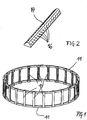
- FIG. 1 shows as a perspective view a cylindrical roller bearing cage with two peripheral elements 11 with indentations for web elements 14 with a uniform trapezoidal cross-section.
- the care Indentations on the peripheral elements 11 in conjunction with the correspondingly shaped recesses in the web elements 14 when assembling the elements 11 and 14 for welding the web elements 14 to the peripheral elements 11 for pre-positioning of the web elements 14 in the circumferential direction of the peripheral elements 11th
- the elements 11 and 14 are made of a ferrous material, in particular of a steel wire. In other embodiments, however, other materials may also be used, and soldering or gluing may occur instead of welding. Furthermore, in particular, the web elements 14 may be designed to achieve a particular sliding behavior, in particular in the region of their contact surfaces towards the rolling elements, with a coating.
- the web elements 14 are provided at their, the roll coats for immediate opposite surfaces provided with recesses 16 for holding a lubricant.
- the recesses 16 are ship-hull-like, you can also say drop-shaped.
- FIG. 2 shows an enlarged perspective view of one of the web elements 14 with the depressions 16.
- the depressions 16 are arranged obliquely in a left axial half of the web elements 14, parallel to a line extending from the right cage area obliquely to the cage center point, formed in the right half corresponding mirror image and in the middle of a recess 16 is radially oriented.
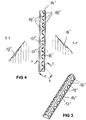
- FIG. 3 shows as an embodiment of the invention in perspective view a web element 14 ', which is an alternative to the web element 14 of Figures 1 and 2 represents.
- the FIG. 4 shows the web element 14 'of FIG. 3 in a plan view of one of the mantle of one of the cylindrical rollers of the cylindrical roller bearing for directly opposite surfaces provided including two with EE and FF designated sections through two adjacent recesses 16 'and 18'.
- Said surface of the stake element comprises three types of ship-hull-like depressions 16 ', 17' and 18 '. All depressions 16 ', 17' are in this case designed to coincide in the circumferential direction of the roll substantially towards one End in the circumferential direction have a decreasing width and depth. Referring to the middle picture of the FIG. 4 The depressions 16 'and 17' decrease, so to speak, substantially toward the right side and the depressions 18 'decrease towards the left side.
- the recesses 16 'and 18' are aligned with their longitudinal extent obliquely to the circumferential direction of the roller, wherein the recesses 16 'relative to the recesses 18' by an equal acute angle relative to said circumferential direction, however, are inclined in opposite directions.
- the depressions 16' are inclined at the same angle, but in the opposite direction, which also applies to the depressions 18 '. Only the recess 17 'is tangentially aligned in the circumferential direction of the roller. The recess 16 'and 18' are arranged alternately and with respect to the recess 17 'axisymmetric.
- the depth of the depressions 16 ', 17' and 18 ' moves in the range of a few tenths of a millimeter down to a few millimeters, the depressions 16', 17 'and 18' over a good part, according to the invention between 90% and 50% of the extension of the surface are formed extending in the roller circumferential direction.
Description
Die Erfindung betrifft einen Rollenlagerkäfig.The invention relates to a roller bearing cage.
Aus dem Stand der Technik sind eine Reihe von Maßnahmen bekannt, um bei geschmierten Wälzlagern mit Käfigen eine ausreichend Schmierstoffversorgung in Wälzkontakt-, aber auch im Gleitkontaktbereichen des Wälzlagers auch bei einer Lebensdauerschmierung sicherzustellen. Ein gattungsgemäßer Rollenlagerkäfig ist z.B. aus der
Eine Aufgabe der vorliegenden Erfindung ist es, einen insbesondere hinsichtlich Schmierstoffversorgung verbesserten Rollenlagerkäfig zu schaffen.An object of the present invention is to provide a roller bearing cage improved in particular with regard to lubricant supply.
Die Aufgabe wird durch den Gegenstand des Anspruchs 1 gelöst. Vorteilhafte Ausgestaltungen sind in den Unteransprüchen beschrieben.The object is solved by the subject matter of claim 1. Advantageous embodiments are described in the subclaims.
Gemäß Anspruch 1 beinhaltet ein Rollenlagerkäfig folgende Merkmale:
- Wenigstens ein Stegelement mit einer zum unmittelbaren Gegenüberliegen einer Mantelfläche einer Rolle vorgesehenen Fläche,
- die Fläche ist mit einer Mehrzahl schiffsrumpfähnlicher makroskopischer Vertiefungen für ein Halten eines Schmierstoffs ausgebildet,
- die Vertiefungen sind in Umfangsrichtung der Rolle, hin zu wenigstens einem Ende in Umfangsrichtung, mit sich verkleinernder Breite und/oder Tiefe ausgebildet, und
- auf der Fläche sind mehrere Vertiefungen angeordnet, von denen sich eine erste Gruppe im Wesentlichen hin zu einem der Enden und die zweite hin zum anderen Ende verkleinert, und
- die Vertiefungen sind sich zwischen 90 % und 50 % der Erstreckung der Fläche in Rollenumfangsrichtung erstrecked ausgebildet.
- At least one web element with a surface provided for the direct opposite of a lateral surface of a roller,
- the surface is formed with a plurality of hull-like macroscopic depressions for holding a lubricant,
- the recesses are formed in the circumferential direction of the roller, towards at least one end in the circumferential direction, with decreasing width and / or depth, and
- on the surface a plurality of depressions are arranged, of which a first group is reduced substantially towards one of the ends and the second towards the other end, and
- the depressions are formed between 90% and 50% of the extent of the surface in the roll circumferential direction.
Die Erfindung beruht dabei auf der Erkenntnis, dass mit der erfindungsgemäßen Ausbildung eines Stegelements auch bei einer Lebensdauerschmierung eine ausreichende Schmierstoffversorgung des Rollenlagers unterstützt wird.The invention is based on the finding that with the inventive design of a rod element even with a lifetime lubrication sufficient lubricant supply of the roller bearing is supported.
Dadurch, dass sich die Vertiefungen in Drehrichtung der Rolle in ihrer Breite und/oder Tiefe verkleinernd ausgebildet sind, wird bei Betrieb des Rollenlagers in den Vertiefungen gehaltener Schmierstoff aufgrund des innerhalb der Vertiefung sozusagen in Drehrichtung kontinuierlich sich verkleinernden Volumensabschnitten aus den Vertiefungen heraus, in die Drehrichtung der Rolle hinein gefördert, und damit der Schmierfilm günstig beeinflusst. Damit dies unabhängig von einer Drehrichtung des Rollenlagers funktioniert, sind hinsichtlich ihrer Verkleinerungsrichtung unterschiedliche Vertiefungen, in Längsrichtung des Stegelements insbesondere abwechselnd vorgesehen.The fact that the recesses are designed to reduce in size in the direction of rotation of the roller in its width and / or depth, is maintained during operation of the roller bearing in the wells lubricant due to the so-called within the recess in the direction of rotation continuously decreasing volume sections out of the wells in the Direction of rotation of the role in promoted, and thus the lubricating film favorably influenced. In order for this to work independently of a direction of rotation of the roller bearing, different recesses are provided with respect to their direction of reduction, in particular alternately in the longitudinal direction of the rod element.
Weitere Vorteile, Merkmale und Einzelheiten der Erfindung ergeben sich aus den im Folgenden beschriebenen Ausführungsbeispielen der Erfindung anhand der Figuren. Dabei zeigen:
- Figur 1
- in perspektivischer Ansicht einen Zylinderrollenlagerkäfig mit zwei Umfangselementen mit Einbauchungen für Stegelemente mit Vertiefungen,
- Figur 2
- in perspektivischer Ansicht eines der Stegelemente der
Figur 1 und - Figur 3
- in perspektivischer Ansicht ein alternatives Stegelement, und
- Figur 4
- das Stegelement der
Figur 3 in einer Draufsicht auf eine der dem Mantel einer der Zylinderrollen des Zylinderrollenlagers zum unmittelbaren Gegenüberliegen vorgesehenen Flächen inklusive zweier mit E-E und F-F bezeichneter Schnitte durch zwei benachbarte Vertiefungen.
- FIG. 1
- a perspective view of a cylindrical roller bearing cage with two peripheral elements with indentations for web elements with recesses,
- FIG. 2
- in a perspective view of one of the web elements of
FIG. 1 and - FIG. 3
- in perspective view, an alternative web element, and
- FIG. 4
- the web element of
FIG. 3 in a plan view of one of the jacket of one of the cylindrical rollers of the cylindrical roller bearing for directly opposite surfaces provided including two with EE and FF designated sections through two adjacent recesses.
Die
Dabei sind die Elemente 11 und 14 aus einem Eisenwerkstoff, insbesondere aus einem Stahldraht hergestellt. In anderen Ausführungsformen können aber auch andere Materialien zum Einsatz kommen und anstelle eines Verschweißens auch ein Löten oder Kleben treten. Weiterhin können insbesondere auch die Stegelemente 14 zum Erzielen eines besonderen Gleitverhaltens, insbesondere im Bereich ihrer Kontaktflächen hin zu den Wälzkörpern, mit einer Beschichtung ausgebildet sein.The
Die Stegelemente 14 sind dabei an ihren, den Rollenmänteln zum unmittelbaren Gegenüberliegen vorgesehenen Flächen, mit Vertiefungen 16 für ein Halten eines Schmierstoffs versehen. Dabei sind die Vertiefungen 16 schiffsrumpfartig, man kann auch sagen tropfenförmig ausgebildet.The
Die
Die
Besagte Fläche des Stegelements umfasst dabei dreierlei Arten von schiffsrumpfartigen Vertiefungen 16', 17' und 18'. Alle Vertiefungen 16', 17' sind dabei übereinstimmend derart ausgebildet, dass sie in Umfangsrichtung der Rolle im Wesentlichen hin zu einem Ende in Umfangsrichtung eine sich verkleinernde Breite und Tiefe aufweisen. Bezugnehmend auf die mittlere Abbildung der
In Abhängigkeit von der Zylinderrollengröße bewegt sich die Tiefe der Vertiefungen 16', 17' und 18' im Bereich weniger Zehntel Millimeter bis hin zu wenigen Millimetern, wobei die Vertiefungen 16', 17' und 18' über einen Gutteil, erfindungsgemäß zwischen 90 % und 50 % der Erstreckung der Fläche in Rollenumfangsrichtung erstreckend ausgebildet sind.Depending on the cylindrical roller size, the depth of the depressions 16 ', 17' and 18 'moves in the range of a few tenths of a millimeter down to a few millimeters, the depressions 16', 17 'and 18' over a good part, according to the invention between 90% and 50% of the extension of the surface are formed extending in the roller circumferential direction.
Claims (13)
- Roller bearing cage, comprising the following features:- at least one web element with a face which is provided for lying directly opposite a circumferential face of a roller,- the face is configured with a plurality of hull-like macroscopic depressions for holding a lubricant,- the depressions are configured with a diminishing width and/or depth in the circumferential direction of the roller, towards at least one end in the circumferential direction,- a plurality of depressions are arranged on the face, of which depressions a first group diminishes substantially towards one of the ends and the second diminishes towards the other end, characterized in that- the depressions are configured so as to extend over between 90% and 50% of the extent of the face in the roller circumferential direction.
- Roller bearing cage according to Claim 1, the depressions which diminish differently in this way being arranged so as to alternate in the longitudinal direction of the web element.
- Roller bearing cage according to either of Claims 1 and 2, the depressions being oriented with their longitudinal extent tangentially or obliquely with respect to the circumferential direction of the roller.
- Roller bearing cage according to Claim 3, depressions which are oriented differently being arranged symmetrically in relation to a centre of the web element.
- Roller bearing cage according to one of Claims 1 to 4, the depth of the depressions being greater than approximately 0.05 mm, in particular greater than approximately 0.1 mm.
- Roller bearing cage according to one of Claims 1 to 5, a plurality of web elements being connected in an integrally joined manner to at least one ring-like circumferential element of the cage.
- Roller bearing cage according to Claim 6, the elements being configured with a shape which is adapted to one another for positioning as intended of the elements with respect to one another for the integrally joined connection, in such a way that the positions of the web elements on the circumferential element are predefined in the circumferential direction and/or in the axial direction of the circumferential element.
- Roller bearing cage according to either of Claims 6 and 7, the elements comprising an iron material and the integrally joined connection comprising a welded joint.
- Roller bearing cage according to one of Claims 6 to 8, the circumferential element on one side and the web elements on the other side being configured with different properties.
- Roller bearing cage according to one of Claims 1 to 9, a cross-sectional face of at least one section of one of the web elements being trapezium-shaped.
- Roller bearing cage according to Claim 10, the sides of the trapezium being of curved configuration in a manner which is adapted to the rollers.
- Roller bearing cage according to one of Claims 1 to 11, the web elements being cut to length from a correspondingly profiled bar or strip stock.
- Roller bearing cage according to one of Claims 1 to 12, the roller bearing cage being configured, in particular, for a cylindrical roller bearing, a tapered roller bearing or a self-aligning roller bearing.
Applications Claiming Priority (2)
| Application Number | Priority Date | Filing Date | Title |
|---|---|---|---|
| DE102008053313.0A DE102008053313B4 (en) | 2008-10-27 | 2008-10-27 | Roller bearing cage |
| PCT/EP2009/007541 WO2010049085A1 (en) | 2008-10-27 | 2009-10-21 | Roller bearing cage |
Publications (2)
| Publication Number | Publication Date |
|---|---|
| EP2347142A1 EP2347142A1 (en) | 2011-07-27 |
| EP2347142B1 true EP2347142B1 (en) | 2018-05-23 |
Family
ID=42028137
Family Applications (1)
| Application Number | Title | Priority Date | Filing Date |
|---|---|---|---|
| EP09737376.5A Not-in-force EP2347142B1 (en) | 2008-10-27 | 2009-10-21 | Roller bearing cage |
Country Status (6)
| Country | Link |
|---|---|
| US (1) | US20110255817A1 (en) |
| EP (1) | EP2347142B1 (en) |
| JP (1) | JP2012506983A (en) |
| CN (1) | CN102203442B (en) |
| DE (1) | DE102008053313B4 (en) |
| WO (1) | WO2010049085A1 (en) |
Families Citing this family (5)
| Publication number | Priority date | Publication date | Assignee | Title |
|---|---|---|---|---|
| DK2659153T3 (en) | 2010-12-27 | 2017-11-06 | Timken Co | Bearing housing for roller bearing assembled by two thread rings and a number of struts or pins |
| US9039289B2 (en) | 2012-06-01 | 2015-05-26 | The Timken Company | Segmented bearing retainer |
| DE102014205817A1 (en) * | 2014-03-28 | 2015-10-01 | Aktiebolaget Skf | Rolling bearing cage and method for mounting a rolling bearing cage |
| US9541127B1 (en) * | 2016-03-23 | 2017-01-10 | Aktiebolaget Skf | Spherical roller bearing |
| US9562563B1 (en) * | 2016-03-24 | 2017-02-07 | Aktiebolaget Skf | Spherical roller bearing |
Family Cites Families (18)
| Publication number | Priority date | Publication date | Assignee | Title |
|---|---|---|---|---|
| US1147497A (en) * | 1914-07-17 | 1915-07-20 | Yellis C Freed | Cage for roller-bearings. |
| DE849500C (en) * | 1941-09-04 | 1952-09-15 | Ver Kugellagerfabriken Ag | One-piece cage for roller bearings |
| DE821447C (en) * | 1949-09-01 | 1952-09-18 | Demag Baggerfabrik G M B H | Cage for roller bearings |
| US3057667A (en) * | 1959-03-06 | 1962-10-09 | Skf Svenska Kullagerfab Ab | Cage for cylindrical roller bearings |
| US3075278A (en) * | 1959-06-03 | 1963-01-29 | Skf Svenska Kullagerfab Ab | Cage for rolling bearings |
| US3365255A (en) * | 1966-03-07 | 1968-01-23 | Gen Motors Corp | Bearing cage |
| US3647273A (en) * | 1970-03-23 | 1972-03-07 | Fmc Corp | Cylindrical roller bearing cage |
| US3877555A (en) * | 1973-06-22 | 1975-04-15 | Ferodo Sa | Assembly cage for free-wheel or bearing |
| US3944307A (en) * | 1974-08-29 | 1976-03-16 | Federal-Mogul Corporation | Plastic bearing cage |
| JP3698735B2 (en) * | 1992-10-02 | 2005-09-21 | 光洋精工株式会社 | Method for manufacturing roller bearing cage |
| NL1007922C2 (en) * | 1997-12-29 | 1999-06-30 | Skf Ind Trading & Dev | Cage with improved holding action. |
| DE19959498A1 (en) * | 1999-12-10 | 2001-06-13 | Schaeffler Waelzlager Ohg | Cage for a rolling bearing |
| DE20113111U1 (en) * | 2001-08-07 | 2001-10-11 | Skf Ab | Plastic cage for rolling bearings |
| DE102004003655A1 (en) * | 2004-01-24 | 2005-08-11 | Ina-Schaeffler Kg | Cage for roller bearing, comprising bridges made of continuously cast profile cut to length for insertion |
| DE102005015971A1 (en) * | 2005-04-07 | 2006-10-12 | Schaeffler Kg | Linear guide with cage chain |
| JP2007010026A (en) * | 2005-06-30 | 2007-01-18 | Ntn Corp | Cylindrical roller bearing and its cage |
| US8523451B2 (en) * | 2005-09-01 | 2013-09-03 | Ntn Corporation | Roller bearing |
| DE102007020113A1 (en) * | 2007-04-28 | 2008-10-30 | Aktiebolaget Skf | Rolling bearing cage |
-
2008
- 2008-10-27 DE DE102008053313.0A patent/DE102008053313B4/en not_active Expired - Fee Related
-
2009
- 2009-10-21 EP EP09737376.5A patent/EP2347142B1/en not_active Not-in-force
- 2009-10-21 WO PCT/EP2009/007541 patent/WO2010049085A1/en active Application Filing
- 2009-10-21 JP JP2011533582A patent/JP2012506983A/en not_active Withdrawn
- 2009-10-21 US US13/126,404 patent/US20110255817A1/en not_active Abandoned
- 2009-10-21 CN CN200980142175.3A patent/CN102203442B/en not_active Expired - Fee Related
Non-Patent Citations (1)
| Title |
|---|
| None * |
Also Published As
| Publication number | Publication date |
|---|---|
| DE102008053313A1 (en) | 2010-05-06 |
| JP2012506983A (en) | 2012-03-22 |
| EP2347142A1 (en) | 2011-07-27 |
| DE102008053313B4 (en) | 2016-10-20 |
| CN102203442B (en) | 2016-10-12 |
| CN102203442A (en) | 2011-09-28 |
| WO2010049085A1 (en) | 2010-05-06 |
| US20110255817A1 (en) | 2011-10-20 |
Similar Documents
| Publication | Publication Date | Title |
|---|---|---|
| EP2142815B1 (en) | Rolling bearing cage composed of a plurality of parts | |
| EP2222974B1 (en) | Rolling bearing cage | |
| EP2347142B1 (en) | Roller bearing cage | |
| WO2007065414A1 (en) | Radial antifriction bearing, especially single-row grooved antifriction bearing | |
| EP2893207B1 (en) | Axial cage for cylindrical rolling elements | |
| DE102011005845A1 (en) | Tapered roller bearing has central recess that is formed in front end of roller into which projections are engaged, where slide bearing element is provided in front ends of inner and outer rings around projections | |
| DE102010003077B4 (en) | plain bearing shell | |
| EP3690268A2 (en) | Rolling element cage for rolling bearings | |
| EP2350481B1 (en) | Rolling bearing cage | |
| DE102004019974B4 (en) | Axle bearing of the rail vehicle | |
| DE102013203674A1 (en) | Cage section and method for its production | |
| DE10240282B4 (en) | radial bearings | |
| WO2007088144A2 (en) | Double-row thin ring bearing comprising inclined rolls | |
| WO2011047920A1 (en) | Radial roller anti-friction bearing having separate sheet-metal rims | |
| WO2015172783A1 (en) | Rolling bearing and method for operating a rolling bearing | |
| DE102004031027A1 (en) | Needle cage for e.g. radial bearing, has guide arranged at front faces of slot and forming stop face for rolling body in radially bent state, where guide has exemptions arranged within area of sections in circumferential directions | |
| DE102005058149A1 (en) | Tapered roller bearings with curved raceways | |
| DE102010014770A1 (en) | Cage i.e. comb lid cage, for cylindrical roller bearing, has bars consisting of soft metallic materials in relation to side rings, where side rings consisting of metallic materials i.e. steel, are spaced from each other in axial direction | |
| DE102007044901B4 (en) | Cylindrical roller bearing cage and roller bearing | |
| DE102017221475A1 (en) | Bearing cage, bearings and procedures | |
| DE102008018380A1 (en) | Roller bearing cage for guiding roller body between two paths of roller bearing, has roller bearing slots whose respective pairs of two corners provided opposite along diagonals exhibit different corner geometries | |
| DE102020209676A1 (en) | bearing cage | |
| DE102014223010A1 (en) | Strand guide roller | |
| DE102005058150A1 (en) | Tapered roller bearings | |
| DE102007059095A1 (en) | Spacer ring for assembly group, has driveshaft section that holds gear wheel at axial distance and spacer ring is supported on inside of drive shaft section |
Legal Events
| Date | Code | Title | Description |
|---|---|---|---|
| PUAI | Public reference made under article 153(3) epc to a published international application that has entered the european phase |
Free format text: ORIGINAL CODE: 0009012 |
|
| 17P | Request for examination filed |
Effective date: 20110516 |
|
| AK | Designated contracting states |
Kind code of ref document: A1 Designated state(s): AT BE BG CH CY CZ DE DK EE ES FI FR GB GR HR HU IE IS IT LI LT LU LV MC MK MT NL NO PL PT RO SE SI SK SM TR |
|
| AX | Request for extension of the european patent |
Extension state: AL BA RS |
|
| DAX | Request for extension of the european patent (deleted) | ||
| 17Q | First examination report despatched |
Effective date: 20120508 |
|
| GRAP | Despatch of communication of intention to grant a patent |
Free format text: ORIGINAL CODE: EPIDOSNIGR1 |
|
| INTG | Intention to grant announced |
Effective date: 20171213 |
|
| GRAS | Grant fee paid |
Free format text: ORIGINAL CODE: EPIDOSNIGR3 |
|
| GRAA | (expected) grant |
Free format text: ORIGINAL CODE: 0009210 |
|
| AK | Designated contracting states |
Kind code of ref document: B1 Designated state(s): AT BE BG CH CY CZ DE DK EE ES FI FR GB GR HR HU IE IS IT LI LT LU LV MC MK MT NL NO PL PT RO SE SI SK SM TR |
|
| REG | Reference to a national code |
Ref country code: GB Ref legal event code: FG4D Free format text: NOT ENGLISH |
|
| REG | Reference to a national code |
Ref country code: CH Ref legal event code: EP |
|
| REG | Reference to a national code |
Ref country code: IE Ref legal event code: FG4D Free format text: LANGUAGE OF EP DOCUMENT: GERMAN |
|
| REG | Reference to a national code |
Ref country code: DE Ref legal event code: R096 Ref document number: 502009014978 Country of ref document: DE |
|
| REG | Reference to a national code |
Ref country code: AT Ref legal event code: REF Ref document number: 1001760 Country of ref document: AT Kind code of ref document: T Effective date: 20180615 |
|
| REG | Reference to a national code |
Ref country code: NL Ref legal event code: MP Effective date: 20180523 |
|
| REG | Reference to a national code |
Ref country code: LT Ref legal event code: MG4D |
|
| PG25 | Lapsed in a contracting state [announced via postgrant information from national office to epo] |
Ref country code: ES Free format text: LAPSE BECAUSE OF FAILURE TO SUBMIT A TRANSLATION OF THE DESCRIPTION OR TO PAY THE FEE WITHIN THE PRESCRIBED TIME-LIMIT Effective date: 20180523 Ref country code: NO Free format text: LAPSE BECAUSE OF FAILURE TO SUBMIT A TRANSLATION OF THE DESCRIPTION OR TO PAY THE FEE WITHIN THE PRESCRIBED TIME-LIMIT Effective date: 20180823 Ref country code: FI Free format text: LAPSE BECAUSE OF FAILURE TO SUBMIT A TRANSLATION OF THE DESCRIPTION OR TO PAY THE FEE WITHIN THE PRESCRIBED TIME-LIMIT Effective date: 20180523 Ref country code: BG Free format text: LAPSE BECAUSE OF FAILURE TO SUBMIT A TRANSLATION OF THE DESCRIPTION OR TO PAY THE FEE WITHIN THE PRESCRIBED TIME-LIMIT Effective date: 20180823 Ref country code: LT Free format text: LAPSE BECAUSE OF FAILURE TO SUBMIT A TRANSLATION OF THE DESCRIPTION OR TO PAY THE FEE WITHIN THE PRESCRIBED TIME-LIMIT Effective date: 20180523 Ref country code: SE Free format text: LAPSE BECAUSE OF FAILURE TO SUBMIT A TRANSLATION OF THE DESCRIPTION OR TO PAY THE FEE WITHIN THE PRESCRIBED TIME-LIMIT Effective date: 20180523 |
|
| PG25 | Lapsed in a contracting state [announced via postgrant information from national office to epo] |
Ref country code: GR Free format text: LAPSE BECAUSE OF FAILURE TO SUBMIT A TRANSLATION OF THE DESCRIPTION OR TO PAY THE FEE WITHIN THE PRESCRIBED TIME-LIMIT Effective date: 20180824 Ref country code: HR Free format text: LAPSE BECAUSE OF FAILURE TO SUBMIT A TRANSLATION OF THE DESCRIPTION OR TO PAY THE FEE WITHIN THE PRESCRIBED TIME-LIMIT Effective date: 20180523 Ref country code: LV Free format text: LAPSE BECAUSE OF FAILURE TO SUBMIT A TRANSLATION OF THE DESCRIPTION OR TO PAY THE FEE WITHIN THE PRESCRIBED TIME-LIMIT Effective date: 20180523 Ref country code: NL Free format text: LAPSE BECAUSE OF FAILURE TO SUBMIT A TRANSLATION OF THE DESCRIPTION OR TO PAY THE FEE WITHIN THE PRESCRIBED TIME-LIMIT Effective date: 20180523 |
|
| PG25 | Lapsed in a contracting state [announced via postgrant information from national office to epo] |
Ref country code: CZ Free format text: LAPSE BECAUSE OF FAILURE TO SUBMIT A TRANSLATION OF THE DESCRIPTION OR TO PAY THE FEE WITHIN THE PRESCRIBED TIME-LIMIT Effective date: 20180523 Ref country code: RO Free format text: LAPSE BECAUSE OF FAILURE TO SUBMIT A TRANSLATION OF THE DESCRIPTION OR TO PAY THE FEE WITHIN THE PRESCRIBED TIME-LIMIT Effective date: 20180523 Ref country code: SK Free format text: LAPSE BECAUSE OF FAILURE TO SUBMIT A TRANSLATION OF THE DESCRIPTION OR TO PAY THE FEE WITHIN THE PRESCRIBED TIME-LIMIT Effective date: 20180523 Ref country code: PL Free format text: LAPSE BECAUSE OF FAILURE TO SUBMIT A TRANSLATION OF THE DESCRIPTION OR TO PAY THE FEE WITHIN THE PRESCRIBED TIME-LIMIT Effective date: 20180523 Ref country code: EE Free format text: LAPSE BECAUSE OF FAILURE TO SUBMIT A TRANSLATION OF THE DESCRIPTION OR TO PAY THE FEE WITHIN THE PRESCRIBED TIME-LIMIT Effective date: 20180523 Ref country code: DK Free format text: LAPSE BECAUSE OF FAILURE TO SUBMIT A TRANSLATION OF THE DESCRIPTION OR TO PAY THE FEE WITHIN THE PRESCRIBED TIME-LIMIT Effective date: 20180523 |
|
| REG | Reference to a national code |
Ref country code: DE Ref legal event code: R097 Ref document number: 502009014978 Country of ref document: DE |
|
| PG25 | Lapsed in a contracting state [announced via postgrant information from national office to epo] |
Ref country code: IT Free format text: LAPSE BECAUSE OF FAILURE TO SUBMIT A TRANSLATION OF THE DESCRIPTION OR TO PAY THE FEE WITHIN THE PRESCRIBED TIME-LIMIT Effective date: 20180523 Ref country code: SM Free format text: LAPSE BECAUSE OF FAILURE TO SUBMIT A TRANSLATION OF THE DESCRIPTION OR TO PAY THE FEE WITHIN THE PRESCRIBED TIME-LIMIT Effective date: 20180523 |
|
| PLBE | No opposition filed within time limit |
Free format text: ORIGINAL CODE: 0009261 |
|
| STAA | Information on the status of an ep patent application or granted ep patent |
Free format text: STATUS: NO OPPOSITION FILED WITHIN TIME LIMIT |
|
| 26N | No opposition filed |
Effective date: 20190226 |
|
| PG25 | Lapsed in a contracting state [announced via postgrant information from national office to epo] |
Ref country code: SI Free format text: LAPSE BECAUSE OF FAILURE TO SUBMIT A TRANSLATION OF THE DESCRIPTION OR TO PAY THE FEE WITHIN THE PRESCRIBED TIME-LIMIT Effective date: 20180523 |
|
| REG | Reference to a national code |
Ref country code: CH Ref legal event code: PL |
|
| GBPC | Gb: european patent ceased through non-payment of renewal fee |
Effective date: 20181021 |
|
| REG | Reference to a national code |
Ref country code: BE Ref legal event code: MM Effective date: 20181031 |
|
| PG25 | Lapsed in a contracting state [announced via postgrant information from national office to epo] |
Ref country code: LU Free format text: LAPSE BECAUSE OF NON-PAYMENT OF DUE FEES Effective date: 20181021 Ref country code: MC Free format text: LAPSE BECAUSE OF FAILURE TO SUBMIT A TRANSLATION OF THE DESCRIPTION OR TO PAY THE FEE WITHIN THE PRESCRIBED TIME-LIMIT Effective date: 20180523 |
|
| REG | Reference to a national code |
Ref country code: IE Ref legal event code: MM4A |
|
| PG25 | Lapsed in a contracting state [announced via postgrant information from national office to epo] |
Ref country code: CH Free format text: LAPSE BECAUSE OF NON-PAYMENT OF DUE FEES Effective date: 20181031 Ref country code: BE Free format text: LAPSE BECAUSE OF NON-PAYMENT OF DUE FEES Effective date: 20181031 Ref country code: LI Free format text: LAPSE BECAUSE OF NON-PAYMENT OF DUE FEES Effective date: 20181031 Ref country code: FR Free format text: LAPSE BECAUSE OF NON-PAYMENT OF DUE FEES Effective date: 20181031 |
|
| PG25 | Lapsed in a contracting state [announced via postgrant information from national office to epo] |
Ref country code: IE Free format text: LAPSE BECAUSE OF NON-PAYMENT OF DUE FEES Effective date: 20181021 Ref country code: GB Free format text: LAPSE BECAUSE OF NON-PAYMENT OF DUE FEES Effective date: 20181021 |
|
| REG | Reference to a national code |
Ref country code: AT Ref legal event code: MM01 Ref document number: 1001760 Country of ref document: AT Kind code of ref document: T Effective date: 20181021 |
|
| PG25 | Lapsed in a contracting state [announced via postgrant information from national office to epo] |
Ref country code: AT Free format text: LAPSE BECAUSE OF NON-PAYMENT OF DUE FEES Effective date: 20181021 Ref country code: MT Free format text: LAPSE BECAUSE OF FAILURE TO SUBMIT A TRANSLATION OF THE DESCRIPTION OR TO PAY THE FEE WITHIN THE PRESCRIBED TIME-LIMIT Effective date: 20180523 |
|
| PG25 | Lapsed in a contracting state [announced via postgrant information from national office to epo] |
Ref country code: TR Free format text: LAPSE BECAUSE OF FAILURE TO SUBMIT A TRANSLATION OF THE DESCRIPTION OR TO PAY THE FEE WITHIN THE PRESCRIBED TIME-LIMIT Effective date: 20180523 |
|
| PG25 | Lapsed in a contracting state [announced via postgrant information from national office to epo] |
Ref country code: PT Free format text: LAPSE BECAUSE OF FAILURE TO SUBMIT A TRANSLATION OF THE DESCRIPTION OR TO PAY THE FEE WITHIN THE PRESCRIBED TIME-LIMIT Effective date: 20180523 |
|
| PG25 | Lapsed in a contracting state [announced via postgrant information from national office to epo] |
Ref country code: HU Free format text: LAPSE BECAUSE OF FAILURE TO SUBMIT A TRANSLATION OF THE DESCRIPTION OR TO PAY THE FEE WITHIN THE PRESCRIBED TIME-LIMIT; INVALID AB INITIO Effective date: 20091021 Ref country code: MK Free format text: LAPSE BECAUSE OF NON-PAYMENT OF DUE FEES Effective date: 20180523 Ref country code: CY Free format text: LAPSE BECAUSE OF FAILURE TO SUBMIT A TRANSLATION OF THE DESCRIPTION OR TO PAY THE FEE WITHIN THE PRESCRIBED TIME-LIMIT Effective date: 20180523 |
|
| PG25 | Lapsed in a contracting state [announced via postgrant information from national office to epo] |
Ref country code: IS Free format text: LAPSE BECAUSE OF FAILURE TO SUBMIT A TRANSLATION OF THE DESCRIPTION OR TO PAY THE FEE WITHIN THE PRESCRIBED TIME-LIMIT Effective date: 20180923 |
|
| PGFP | Annual fee paid to national office [announced via postgrant information from national office to epo] |
Ref country code: DE Payment date: 20201228 Year of fee payment: 12 |
|
| REG | Reference to a national code |
Ref country code: DE Ref legal event code: R119 Ref document number: 502009014978 Country of ref document: DE |
|
| PG25 | Lapsed in a contracting state [announced via postgrant information from national office to epo] |
Ref country code: DE Free format text: LAPSE BECAUSE OF NON-PAYMENT OF DUE FEES Effective date: 20220503 |