EP2347104B1 - Procede de diagnostic des performances d'un pot catalytique - Google Patents
Procede de diagnostic des performances d'un pot catalytique Download PDFInfo
- Publication number
- EP2347104B1 EP2347104B1 EP09752787A EP09752787A EP2347104B1 EP 2347104 B1 EP2347104 B1 EP 2347104B1 EP 09752787 A EP09752787 A EP 09752787A EP 09752787 A EP09752787 A EP 09752787A EP 2347104 B1 EP2347104 B1 EP 2347104B1
- Authority
- EP
- European Patent Office
- Prior art keywords
- converter
- signal
- diagnosis
- catalytic converter
- probes
- Prior art date
- Legal status (The legal status is an assumption and is not a legal conclusion. Google has not performed a legal analysis and makes no representation as to the accuracy of the status listed.)
- Not-in-force
Links
Images

Classifications
-
- F—MECHANICAL ENGINEERING; LIGHTING; HEATING; WEAPONS; BLASTING
- F01—MACHINES OR ENGINES IN GENERAL; ENGINE PLANTS IN GENERAL; STEAM ENGINES
- F01N—GAS-FLOW SILENCERS OR EXHAUST APPARATUS FOR MACHINES OR ENGINES IN GENERAL; GAS-FLOW SILENCERS OR EXHAUST APPARATUS FOR INTERNAL-COMBUSTION ENGINES
- F01N11/00—Monitoring or diagnostic devices for exhaust-gas treatment apparatus
- F01N11/007—Monitoring or diagnostic devices for exhaust-gas treatment apparatus the diagnostic devices measuring oxygen or air concentration downstream of the exhaust apparatus
-
- F—MECHANICAL ENGINEERING; LIGHTING; HEATING; WEAPONS; BLASTING
- F01—MACHINES OR ENGINES IN GENERAL; ENGINE PLANTS IN GENERAL; STEAM ENGINES
- F01N—GAS-FLOW SILENCERS OR EXHAUST APPARATUS FOR MACHINES OR ENGINES IN GENERAL; GAS-FLOW SILENCERS OR EXHAUST APPARATUS FOR INTERNAL-COMBUSTION ENGINES
- F01N3/00—Exhaust or silencing apparatus having means for purifying, rendering innocuous, or otherwise treating exhaust
- F01N3/08—Exhaust or silencing apparatus having means for purifying, rendering innocuous, or otherwise treating exhaust for rendering innocuous
- F01N3/10—Exhaust or silencing apparatus having means for purifying, rendering innocuous, or otherwise treating exhaust for rendering innocuous by thermal or catalytic conversion of noxious components of exhaust
- F01N3/18—Exhaust or silencing apparatus having means for purifying, rendering innocuous, or otherwise treating exhaust for rendering innocuous by thermal or catalytic conversion of noxious components of exhaust characterised by methods of operation; Control
- F01N3/20—Exhaust or silencing apparatus having means for purifying, rendering innocuous, or otherwise treating exhaust for rendering innocuous by thermal or catalytic conversion of noxious components of exhaust characterised by methods of operation; Control specially adapted for catalytic conversion
-
- F—MECHANICAL ENGINEERING; LIGHTING; HEATING; WEAPONS; BLASTING
- F01—MACHINES OR ENGINES IN GENERAL; ENGINE PLANTS IN GENERAL; STEAM ENGINES
- F01N—GAS-FLOW SILENCERS OR EXHAUST APPARATUS FOR MACHINES OR ENGINES IN GENERAL; GAS-FLOW SILENCERS OR EXHAUST APPARATUS FOR INTERNAL-COMBUSTION ENGINES
- F01N2550/00—Monitoring or diagnosing the deterioration of exhaust systems
- F01N2550/02—Catalytic activity of catalytic converters
-
- F—MECHANICAL ENGINEERING; LIGHTING; HEATING; WEAPONS; BLASTING
- F01—MACHINES OR ENGINES IN GENERAL; ENGINE PLANTS IN GENERAL; STEAM ENGINES
- F01N—GAS-FLOW SILENCERS OR EXHAUST APPARATUS FOR MACHINES OR ENGINES IN GENERAL; GAS-FLOW SILENCERS OR EXHAUST APPARATUS FOR INTERNAL-COMBUSTION ENGINES
- F01N2560/00—Exhaust systems with means for detecting or measuring exhaust gas components or characteristics
- F01N2560/02—Exhaust systems with means for detecting or measuring exhaust gas components or characteristics the means being an exhaust gas sensor
- F01N2560/025—Exhaust systems with means for detecting or measuring exhaust gas components or characteristics the means being an exhaust gas sensor for measuring or detecting O2, e.g. lambda sensors
-
- F—MECHANICAL ENGINEERING; LIGHTING; HEATING; WEAPONS; BLASTING
- F01—MACHINES OR ENGINES IN GENERAL; ENGINE PLANTS IN GENERAL; STEAM ENGINES
- F01N—GAS-FLOW SILENCERS OR EXHAUST APPARATUS FOR MACHINES OR ENGINES IN GENERAL; GAS-FLOW SILENCERS OR EXHAUST APPARATUS FOR INTERNAL-COMBUSTION ENGINES
- F01N2560/00—Exhaust systems with means for detecting or measuring exhaust gas components or characteristics
- F01N2560/14—Exhaust systems with means for detecting or measuring exhaust gas components or characteristics having more than one sensor of one kind
-
- F—MECHANICAL ENGINEERING; LIGHTING; HEATING; WEAPONS; BLASTING
- F01—MACHINES OR ENGINES IN GENERAL; ENGINE PLANTS IN GENERAL; STEAM ENGINES
- F01N—GAS-FLOW SILENCERS OR EXHAUST APPARATUS FOR MACHINES OR ENGINES IN GENERAL; GAS-FLOW SILENCERS OR EXHAUST APPARATUS FOR INTERNAL-COMBUSTION ENGINES
- F01N2900/00—Details of electrical control or of the monitoring of the exhaust gas treating apparatus
- F01N2900/06—Parameters used for exhaust control or diagnosing
- F01N2900/16—Parameters used for exhaust control or diagnosing said parameters being related to the exhaust apparatus, e.g. particulate filter or catalyst
- F01N2900/1621—Catalyst conversion efficiency
-
- Y—GENERAL TAGGING OF NEW TECHNOLOGICAL DEVELOPMENTS; GENERAL TAGGING OF CROSS-SECTIONAL TECHNOLOGIES SPANNING OVER SEVERAL SECTIONS OF THE IPC; TECHNICAL SUBJECTS COVERED BY FORMER USPC CROSS-REFERENCE ART COLLECTIONS [XRACs] AND DIGESTS
- Y02—TECHNOLOGIES OR APPLICATIONS FOR MITIGATION OR ADAPTATION AGAINST CLIMATE CHANGE
- Y02A—TECHNOLOGIES FOR ADAPTATION TO CLIMATE CHANGE
- Y02A50/00—TECHNOLOGIES FOR ADAPTATION TO CLIMATE CHANGE in human health protection, e.g. against extreme weather
- Y02A50/20—Air quality improvement or preservation, e.g. vehicle emission control or emission reduction by using catalytic converters
-
- Y—GENERAL TAGGING OF NEW TECHNOLOGICAL DEVELOPMENTS; GENERAL TAGGING OF CROSS-SECTIONAL TECHNOLOGIES SPANNING OVER SEVERAL SECTIONS OF THE IPC; TECHNICAL SUBJECTS COVERED BY FORMER USPC CROSS-REFERENCE ART COLLECTIONS [XRACs] AND DIGESTS
- Y02—TECHNOLOGIES OR APPLICATIONS FOR MITIGATION OR ADAPTATION AGAINST CLIMATE CHANGE
- Y02T—CLIMATE CHANGE MITIGATION TECHNOLOGIES RELATED TO TRANSPORTATION
- Y02T10/00—Road transport of goods or passengers
- Y02T10/10—Internal combustion engine [ICE] based vehicles
- Y02T10/40—Engine management systems
Definitions
- the field of the invention is that of catalytic converters of gasoline motor vehicles and more particularly the onboard diagnosis of these pots.
- a catalytic converter is a member that is mounted on the exhaust line of the engine of the vehicle, upstream of a silencer. It is a filter designed to reduce emissions of gaseous pollutants (HC, CO, NOx ). More particularly, it is a ceramic bar having channels coated internally with a catalyst and through which the exhaust gas.
- gaseous pollutants HC, CO, NOx
- the signal from the upstream sensor has a sinusoidal appearance, like the richness regulation of the mixture admitted by the engine, which oscillates alternately between rich and poor phases. This alternation makes it possible to have an optimal conversion of the exhaust gases by the catalytic converter.
- the signal of the downstream probe is a virtually flat signal.
- the signal from the downstream probe is disturbed, varied and progressively amplified to assume a sinusoidal shape.
- the post-catalytic signal of the downstream probe is almost identical to that of the upstream probe, only offset in time the interval that is necessary for the gas to pass from one to the other of the two probes.
- the diagnosis consists in comparing the post-catalytic signal of the diagnosed pot with the post-catalytic signal of a reference catalytic converter.
- the passive diagnostic method is no longer of sufficient precision to meet the current detection criteria.
- the diagnosis has also evolved and the process of passive diagnosis has been abandoned in favor of a so-called intrusive process.
- the intrusive method while continuing to use two upstream and downstream oxygen probes, and whose respective signals are compared, it is involved in the operation of the engine, hence the qualifier of intrusive, by stimulating oxygen probes with a succession of wealth slots.
- Each stimulus consists of injecting more gasoline after the engine has been stabilized for a certain period, for example 3s.
- the intrusive diagnosis is based on the measurement of oxygen storage capacity (OSC).
- OSC oxygen storage capacity
- the report Cr Air Real fuel Air Stroichiometric fuel is equal to 1.
- the stimulus that is provoked is, in the signal of the upstream probe Sa, a double gap of richness with a first poor niche (excess of air), with a ratio Cr here greater than 1, and a second rich niche (excess of fuel), with a ratio Cr here of less than 1, as illustrated on the figure 2 .
- the post-catalytic signal Sp reproduces the double slot of richness virtually identical to that of the upstream signal Sa, but with a time lag of ⁇ t (n).
- the intrusive diagnostic method is much more accurate than the passive diagnosis. As soon as ⁇ t (n) reaches a low threshold, an alert is triggered.
- a catalytic converter has the function of reducing the emissions of polluting gases, but the stimuli of intrusive diagnoses, with their enrichment and depletion phases, are causes of pollution and, whatever the state of the catalytic converters.
- the paradox is also evident especially when the pots are new and prevent pollution.
- the invention relates to a method for diagnosing the performance of a catalytic converter of a motor vehicle gasoline, on board the vehicle, the pot being mounted on the vehicle exhaust line, in which process two oxygen probes are placed on the exhaust line respectively upstream and downstream of the pot, their signals are analyzed, and the signal of the downstream probe is compared to a threshold to carry out a passive diagnosis during a first period of the life of the pot, to beyond which, during a final period of the life of the pot, using both probes and a diagnostic automaton, and by measuring the oxygen storage capacity of the pot, an intrusive diagnosis of pot performance is carried out.
- the transition between the passive diagnosis and the intrusive diagnosis is predetermined by the crossing of a low threshold by the time offset between the two signals of the two probes, the threshold being determined at will because not standardized.
- the transition threshold is determined by an emission level of a standard in force, for example Euro 5.
Landscapes
- Engineering & Computer Science (AREA)
- Chemical & Material Sciences (AREA)
- Chemical Kinetics & Catalysis (AREA)
- Combustion & Propulsion (AREA)
- Mechanical Engineering (AREA)
- General Engineering & Computer Science (AREA)
- Health & Medical Sciences (AREA)
- Toxicology (AREA)
- Exhaust Gas After Treatment (AREA)
Description
- Le domaine de l'invention est celui des pots catalytiques des véhicules automobiles à essence et plus particulièrement du diagnostic embarqué de ces pots.
- Un pot catalytique est un organe qui est monté sur la ligne d'échappement du moteur du véhicule, en amont d'un silencieux. C'est un filtre destiné à réduire les émissions de gaz polluants (HC, CO, NOx...).
Plus particulièrement, il s'agit d'un pain de céramique comportant des canaux revêtus intérieurement d'un catalyseur et que traversent les gaz d'échappement. - Depuis un certain temps déjà, les administrations, notamment celles de l'Union Européenne, ont édicté des normes qui ont contraint les constructeurs à monter des pots catalytiques de plus en plus performants et à offrir un service de diagnostic embarqué des performances des pots au cours de leur vieillissement.
- Un tel procédé de diagnostic des performances d'un pot catalytic est connu du
JP 08 177 469 A - On a commencé par proposer un procédé de diagnostic dit passif, dans la mesure où il s'agit d'observer, sans intervenir. On utilise à cet effet un système à deux sondes à oxygène placées respectivement dans la tuyauterie d'échappement en amont et en aval du pot catalytique. En pratique, on n'observe que le signal de la sonde aval. Les sondes à oxygène mesurent la tension électrique engendrée par le déplacement des ions d'oxygène présents dans les gaz d'échappement.
- Le signal de la sonde amont a une allure de sinusoïde, à l'image de la régulation de richesse du mélange admis par le moteur, qui oscille en alternant les phases riches et les phases pauvres. Cette alternance permet d'avoir une conversion optimale des gaz d'échappement par le pot catalytique.
- Au début de son utilisation, à l'état neuf du pot, le signal de la sonde aval est un signal quasiment plat. Au fur et à mesure du vieillissement du pot catalytique, le signal de la sonde aval se perturbe, varie et s'amplifie progressivement pour prendre une forme également sinusoïdale. En fin de vie du pot catalytique, le catalyseur n'agissant plus, le signal post-catalytique de la sonde aval est quasiment identique à celui de la sonde amont, seulement décalé dans le temps de l'intervalle qui est nécessaire aux gaz pour transiter de l'une à l'autre des deux sondes.
- Le diagnostic consiste à comparer le signal post-catalytique du pot diagnostiqué au signal post-catalytique d'un pot catalytique de référence.
- Chaque évolution de la norme impose des seuils de détection de plus en plus faibles.
- Le procédé de diagnostic passif n'est donc plus d'une précision suffisante pour satisfaire les critères de détection actuels. Comme la norme a évolué, le diagnostic a aussi évolué et le procédé de diagnostic passif a été délaissé au profit d'un procédé dit intrusif.
- Selon le procédé intrusif, tout en continuant d'utiliser deux sondes à oxygène amont et aval, et dont on compare les signaux respectifs, on intervient dans le fonctionnement du moteur, d'où le qualificatif d'intrusif, en stimulant les sondes à oxygène avec un enchaînement de créneaux de richesse. Chaque stimulus consiste à injecter plus d'essence après que le moteur ait été stabilisé pendant une certaine période, par exemple de 3s. Le diagnostic intrusif est basé sur la mesure de la capacité de stockage d'oxygène (OSC).
En régime normal, le rapport
est égal à 1. - Le stimulus qu'on provoque est, dans le signal de la sonde amont Sa, un double créneau de richesse avec un premier créneau pauvre (excès d'air), avec un rapport Cr ici supérieur à 1, et un deuxième créneau riche (excès de carburant), avec un rapport Cr ici inférieur à 1, comme illustré sur la
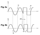
figure 2 . Lorsque le pot catalytique est neuf, le signal post-catalytique Sp reproduit le double créneau de richesse pratiquement identique à celui du signal amont Sa, mais avec un décalage dans le temps de Δt (n). - En fin de vie efficace du pot catalytique, alors que la portion du signal post-catalytique hors créneau de richesse devient également sinusoïdale, quasi identique à celle du signal amont Sa, le stimulus se traduit dans le signal post-catalytique Sp par un double créneau pratiquement identique à celui du signal amont Sa mais décalé dans le temps de Δt (v) beaucoup plus petit que Δt (n) (
figure 3 ). - Comme les caractéristiques du double créneau peuvent être parfaitement maîtrisées par le logiciel de l'automate de diagnostic, au contraire des portions sinusoïdales des courbes des signaux Sa et Sp, le procédé de diagnostic intrusif est beaucoup plus précis que le diagnostic passif. Dès que Δt (n) atteint un seuil bas, on provoque une alerte.
- La demanderesse a proposé son invention après avoir réalisé le côté paradoxal du diagnostic intrusif. Un pot catalytique a pour fonction de réduire les émanations de gaz polluants, Or les stimuli des diagnostics intrusifs, avec leurs phases d'enrichissement et d'appauvrissement, sont des causes de pollution et, ce, quelque soit l'état des pots catalytiques. Le paradoxe se manifeste d'ailleurs surtout quand les pots sont neufs et empêchent la pollution.
- Et bien la demanderesse a osé braver la tendance qui veut de plus en plus de précisions pour revenir en arrière et proposer à nouveau un diagnostic passif pendant une première partie de la durée de vie des pots catalytiques pour, ensuite, satisfaire à nouveau les exigences normatives et repasser au-delà à un diagnostic intrusif pendant une deuxième partie de la durée de vie des pots catalytiques, la plus cruciale au plan de la pollution.
- Au-delà du paradoxe mis en évidence et de l'audace d'un retour en arrière, la demanderesse a finalement fait preuve d'un simple bon sens en basant son invention sur le fait que les normes étant de plus en plus sévères, les constructeurs mettaient forcément sur le marché des pots catalytiques performants, au moins pendant un certain temps. Tout cela ne peut que constituer un gage d'activité inventive.
- Ainsi l'invention concerne un procédé de diagnostic des performances d'un pot catalytique de véhicule automobile à essence, à bord du véhicule, le pot étant monté sur la ligne d'échappement du véhicule, procédé dans lequel on place deux sondes à oxygène sur la ligne d'échappement respectivement en amont et en aval du pot, on analyse leurs signaux, et on compare le signal de la sonde aval à un seuil pour procéder à un diagnostic passif pendant une première période de la durée de vie du pot, au-delà de laquelle, pendant une dernière période de la durée de vie du pot, à l'aide des deux sondes et d'un automate de diagnostic, et par mesure de la capacité de stockage d'oxygène du pot, on procède à un diagnostic intrusif des performances du pot.
- Avantageusement la transition entre le diagnostic passif et le diagnostic intrusif est prédéterminée par le franchissement d'un seuil bas par le décalage temporel entre les deux signaux des deux sondes, le seuil étant déterminé à volonté car non normé.
- De préférence, le seuil de transition est déterminé par un niveau d'émission d'une norme en vigueur, par exemple Euro 5.
- En référence à la
figure 1 , qui représente schématiquement une ligne d'échappement d'un moteur de véhicule automobile à essence, la ligne d'échappement 1 du véhicule automobile comprend, sur la tuyauterie 2, un pot catalytique 3 et, en aval du pot 3, un silencieux 4. Deux sondes à oxygène 5, 6 sont placées sur la tuyauterie 2 respectivement en amont (5) et en aval (6) du pot 3. La sonde aval 6 (Sp) est une sonde post-catalytique, la sonde amont 5 (Sa), une sonde pré-catalytique. Lafigure 2 correspond aux signaux des sondes Sa et Sp associées à un pot catalytique pratiquement neuf. On a représenté, sur lafigure 2 , le signal de la sonde pré- catalytique (Sa) 5 en phase de diagnostic intrusif. Avant le stimulus, le signal est une sinusoïde classique 7 constituée d'alternances d'état riche et d'état pauvre. Le stimulus 8 est illustré par un créneau à un état haut 9 suivi d'un créneau à un état bas 10. Après le stimulus, la courbe reprend sa forme sinusoïdale. Sur lafigure 2b , la courbe 16 du signal de la sonde post-catalytique (Sp) 6, avant et après le stimulus 11, est pratiquement plate. Les créneaux de stimulus 11 du signal de la sonde post-catalytique 6 sont quasiment les mêmes que ceux du signal de la sonde 5, mais décalés de Δt (n). Lesfigures 3a, 3b représentent les signaux des deux sondes 5 (5a), 6 (Sp) mais le pot catalytique 3 étant déjà usagé.
Les courbes de ces figures se distinguent de celles desfigures 2a, 2b par : - 1) avant et après le stimulus, la courbe du signal de la sonde post-catalytique 6 est une sinusoïde pratiquement identique à celle de la courbe du signal de la sonde pré-catalytique 5,
- 2) les créneaux de stimulus 13 de la courbe 12 du signal 15 de la sonde 6 sont décalés par rapport à ceux de la courbe 14 du signal de la sonde 5 de Δt (v), beaucoup plus petit que Δt (n).
Claims (3)
- Procédé de diagnostic des performances d'un pot catalytique (3) de véhicule automobile à essence, à bord du véhicule, le pot catalytique étant monté sur la ligne d'échappement (1) du véhicule, procédé dans lequel on place deux sondes à oxygène (5, 6) sur la ligne d'échappement (1) respectivement en amont et en aval du pot (3), on analyse leurs signaux (7, 16) et on compare le signal (16) de la sonde aval (6) à un seuil pour procéder à un diagnostic passif pendant une première période de la durée de vie du pot (3), au-delà de laquelle, pendant une dernière période de la durée de vie du pot (3), à l'aide des deux sondes (5, 6) et d'un automate de diagnostic et, par mesure de la capacité de stockage d'oxygène du pot (3), on procède à un diagnostic intrusif des performances du pot (3).
- Procédé de diagnostic selon la revendication 1, dans lequel la transition entre le diagnostic passif et le diagnostic intrusif est prédéterminée par le franchissement d'un seuil bas par le décalage temporel entre les deux signaux (7, 16) des deux sondes (5, 6).
- Procédé de diagnostic selon la revendication 2, dans lequel le seuil de transition est déterminé par un niveau d'émission d'une norme en vigueur.
Applications Claiming Priority (2)
| Application Number | Priority Date | Filing Date | Title |
|---|---|---|---|
| FR0806209A FR2938008B1 (fr) | 2008-11-06 | 2008-11-06 | Procede de diagnostic des performances d'un pot catalytique |
| PCT/EP2009/064667 WO2010052261A1 (fr) | 2008-11-06 | 2009-11-05 | Procede de diagnostic des performances d'un pot catalytique |
Publications (2)
| Publication Number | Publication Date |
|---|---|
| EP2347104A1 EP2347104A1 (fr) | 2011-07-27 |
| EP2347104B1 true EP2347104B1 (fr) | 2013-01-09 |
Family
ID=40756731
Family Applications (1)
| Application Number | Title | Priority Date | Filing Date |
|---|---|---|---|
| EP09752787A Not-in-force EP2347104B1 (fr) | 2008-11-06 | 2009-11-05 | Procede de diagnostic des performances d'un pot catalytique |
Country Status (11)
| Country | Link |
|---|---|
| US (1) | US8910510B2 (fr) |
| EP (1) | EP2347104B1 (fr) |
| JP (1) | JP5658163B2 (fr) |
| KR (1) | KR101612581B1 (fr) |
| CN (1) | CN102209838B (fr) |
| BR (1) | BRPI0921427A2 (fr) |
| FR (1) | FR2938008B1 (fr) |
| MX (1) | MX2011004711A (fr) |
| MY (1) | MY148498A (fr) |
| RU (1) | RU2516058C2 (fr) |
| WO (1) | WO2010052261A1 (fr) |
Families Citing this family (6)
| Publication number | Priority date | Publication date | Assignee | Title |
|---|---|---|---|---|
| CN102374001B (zh) * | 2010-08-06 | 2013-07-10 | 长春易控汽车电子有限公司 | 发动机催化转化器老化故障诊断方法 |
| FR2979949B1 (fr) * | 2011-09-13 | 2015-02-20 | Peugeot Citroen Automobiles Sa | Procede et dispositif de detection d'un organe de depollution dans une ligne d'echappement d'un vehicule automobile, ligne d'echappement et vehicule automobile comprenant un tel dispositif |
| DE102012007897A1 (de) * | 2012-04-23 | 2013-10-24 | Man Truck & Bus Ag | Verfahren und Vorrichtung zu Überprüfung der Funktionsfähigkeit eines NO-Oxidationskatalysators |
| US9261033B2 (en) * | 2014-05-22 | 2016-02-16 | Ford Global Technologies, Llc | Systems and methods for improving catalyst diagnostics in the presence of sensor degradation |
| US10436762B2 (en) * | 2017-11-07 | 2019-10-08 | Chevron Phillips Chemical Company Lp | System and method for monitoring a reforming catalyst |
| FR3101668B1 (fr) * | 2019-10-07 | 2022-06-24 | Renault Sas | Procede de diagnostic d’un systeme de post-traitement d’un moteur a allumage commande |
Family Cites Families (12)
| Publication number | Priority date | Publication date | Assignee | Title |
|---|---|---|---|---|
| JPH0374540A (ja) * | 1989-08-17 | 1991-03-29 | Mitsubishi Electric Corp | 内燃機関の空燃比制御装置 |
| RU2059080C1 (ru) * | 1994-11-03 | 1996-04-27 | Акционерное общество "Элкар" | Способ бортовой диагностики каталитического нейтрализатора отработавших газов транспортного двигателя внутреннего сгорания |
| JP3149714B2 (ja) * | 1994-12-28 | 2001-03-26 | 日産自動車株式会社 | 内燃機関の触媒劣化診断装置 |
| EP1471221B1 (fr) * | 1995-10-26 | 2006-03-15 | Toyota Jidosha Kabushiki Kaisha | Dispositif pour la détection de la détérioration d' un catalyseur pour un moteur à combustion interne |
| US5842339A (en) * | 1997-02-26 | 1998-12-01 | Motorola Inc. | Method for monitoring the performance of a catalytic converter |
| DE19963903A1 (de) * | 1999-12-31 | 2001-07-12 | Bosch Gmbh Robert | Verfahren zum Betreiben einer Brennkraftmaschine insbesondere eines Kraftfahrzeugs |
| DE19963932A1 (de) * | 1999-12-31 | 2001-07-12 | Bosch Gmbh Robert | Verfahren zum Betreiben einer Brennkraftmaschine insbesondere eines Kraftfahrzeugs |
| JP2002256856A (ja) * | 2001-03-06 | 2002-09-11 | Mitsubishi Motors Corp | 排気浄化触媒の劣化検出装置 |
| US6868666B2 (en) * | 2003-04-08 | 2005-03-22 | General Motors Corporation | Method and apparatus for monitoring catalyst efficiency and outlet oxygen sensor performance |
| JP4089507B2 (ja) * | 2003-05-20 | 2008-05-28 | トヨタ自動車株式会社 | 内燃機関の触媒劣化検出装置 |
| JP2006257904A (ja) | 2005-03-15 | 2006-09-28 | Toyota Motor Corp | 内燃機関の触媒劣化判定装置 |
| JP4636273B2 (ja) * | 2006-06-07 | 2011-02-23 | 三菱自動車工業株式会社 | 内燃機関の排気浄化装置 |
-
2008
- 2008-11-06 FR FR0806209A patent/FR2938008B1/fr not_active Expired - Fee Related
-
2009
- 2009-11-05 MX MX2011004711A patent/MX2011004711A/es active IP Right Grant
- 2009-11-05 MY MYPI2011001852A patent/MY148498A/en unknown
- 2009-11-05 RU RU2011122619/06A patent/RU2516058C2/ru not_active IP Right Cessation
- 2009-11-05 BR BRPI0921427A patent/BRPI0921427A2/pt not_active IP Right Cessation
- 2009-11-05 EP EP09752787A patent/EP2347104B1/fr not_active Not-in-force
- 2009-11-05 JP JP2011535106A patent/JP5658163B2/ja not_active Expired - Fee Related
- 2009-11-05 US US13/127,302 patent/US8910510B2/en active Active
- 2009-11-05 KR KR1020117012884A patent/KR101612581B1/ko not_active Expired - Fee Related
- 2009-11-05 WO PCT/EP2009/064667 patent/WO2010052261A1/fr not_active Ceased
- 2009-11-05 CN CN2009801442196A patent/CN102209838B/zh not_active Expired - Fee Related
Also Published As
| Publication number | Publication date |
|---|---|
| FR2938008B1 (fr) | 2010-11-26 |
| BRPI0921427A2 (pt) | 2017-06-06 |
| MY148498A (en) | 2013-04-30 |
| CN102209838B (zh) | 2013-05-29 |
| JP5658163B2 (ja) | 2015-01-21 |
| EP2347104A1 (fr) | 2011-07-27 |
| FR2938008A1 (fr) | 2010-05-07 |
| MX2011004711A (es) | 2011-08-15 |
| CN102209838A (zh) | 2011-10-05 |
| WO2010052261A1 (fr) | 2010-05-14 |
| KR20110082607A (ko) | 2011-07-19 |
| RU2516058C2 (ru) | 2014-05-20 |
| KR101612581B1 (ko) | 2016-04-14 |
| JP2012511652A (ja) | 2012-05-24 |
| RU2011122619A (ru) | 2012-12-20 |
| US8910510B2 (en) | 2014-12-16 |
| US20110252867A1 (en) | 2011-10-20 |
Similar Documents
| Publication | Publication Date | Title |
|---|---|---|
| US8307633B2 (en) | Engine exhaust gas purification apparatus enabling accurate judgement of appropriate time for terminating NOx catalyst regeneration procedure | |
| CN106996326B (zh) | 监测排气后处理系统的方法 | |
| US9416708B2 (en) | Method for determining HC-conversion efficiency of a catalyst, a diagnostic device configured to carry out the method as well as a motor vehicle having such a catalyst | |
| EP3146176B1 (fr) | Procédé de diagnostic de l'efficacité d'un catalyseur trois voies | |
| FR3029973A1 (fr) | Procede de surveillance d'un dispositif de catalyse d'oxydation | |
| US10450986B2 (en) | Method for diagnosing an exhaust gas system of an internal combustion engine | |
| WO2010052261A1 (fr) | Procede de diagnostic des performances d'un pot catalytique | |
| US20120222401A1 (en) | Method for operating an exhaust system of an internal combustion engine | |
| Peckham et al. | Analysis of transient HC, CO, NOx and CO2 emissions from a GDI engine using fast response gas analyzers | |
| FR2899277A1 (fr) | Procede de commande pilote d'un coefficient lambda. | |
| JP2020041445A (ja) | 触媒劣化診断方法および触媒劣化診断システム | |
| EP3612723A1 (fr) | Procede de determination du vieillissement d'un catalyseur de ligne d'echappement de vehicule automobile | |
| FR2807473A1 (fr) | Dispositif et procede pour coordonner des mesures a prendre concernant les gaz d'echappement | |
| JP2020041444A (ja) | 触媒劣化診断方法および触媒劣化診断システム | |
| EP4041998B1 (fr) | Procédé de diagnostic d'un système de post-traitement d'un moteur à allumage commandé | |
| US20080105031A1 (en) | Method and Device for Diagnosis of an Exhaust Gas Cleaning System | |
| FR3030622A1 (fr) | Procede de surveillance d'un catalyseur d'oxydation de methane | |
| FR3053732A1 (fr) | Procede de controle d'un etat de fonctionnement d'un systeme de reduction catalytique selective des oxydes d'azote pour un vehicule | |
| FR2849471A1 (fr) | Procede pour le diagnostic d'un catalyseur dans un flux de gaz d'echappement d'un moteur a combustion interne et dispositif pour la mise en oeuvre du procede | |
| US20080279742A1 (en) | Method and Device For Desulfating a NOx Storage Catalyst | |
| EP3034827B1 (fr) | Procédé de diagnostic d'un piège à oxydes d'azote et dispositif associé | |
| EP2961955B1 (fr) | Procede de detection d'un dysfonctionnement d'un systeme de reduction catalytique selective | |
| CN115142938A (zh) | 内燃机装置 | |
| FR2856732A1 (fr) | Procede et dispositif pour influencer la temperature d'un systeme catalytique | |
| FR2862085A1 (fr) | Procede de controle de l'etat d'un convertisseur catalytique d'un vehicule automobile |
Legal Events
| Date | Code | Title | Description |
|---|---|---|---|
| PUAI | Public reference made under article 153(3) epc to a published international application that has entered the european phase |
Free format text: ORIGINAL CODE: 0009012 |
|
| 17P | Request for examination filed |
Effective date: 20110606 |
|
| AK | Designated contracting states |
Kind code of ref document: A1 Designated state(s): AT BE BG CH CY CZ DE DK EE ES FI FR GB GR HR HU IE IS IT LI LT LU LV MC MK MT NL NO PL PT RO SE SI SK SM TR |
|
| AX | Request for extension of the european patent |
Extension state: AL BA RS |
|
| DAX | Request for extension of the european patent (deleted) | ||
| 17Q | First examination report despatched |
Effective date: 20120314 |
|
| GRAP | Despatch of communication of intention to grant a patent |
Free format text: ORIGINAL CODE: EPIDOSNIGR1 |
|
| GRAS | Grant fee paid |
Free format text: ORIGINAL CODE: EPIDOSNIGR3 |
|
| GRAA | (expected) grant |
Free format text: ORIGINAL CODE: 0009210 |
|
| AK | Designated contracting states |
Kind code of ref document: B1 Designated state(s): AT BE BG CH CY CZ DE DK EE ES FI FR GB GR HR HU IE IS IT LI LT LU LV MC MK MT NL NO PL PT RO SE SI SK SM TR |
|
| REG | Reference to a national code |
Ref country code: GB Ref legal event code: FG4D Free format text: NOT ENGLISH |
|
| REG | Reference to a national code |
Ref country code: CH Ref legal event code: EP Ref country code: AT Ref legal event code: REF Ref document number: 592880 Country of ref document: AT Kind code of ref document: T Effective date: 20130115 |
|
| REG | Reference to a national code |
Ref country code: IE Ref legal event code: FG4D Free format text: LANGUAGE OF EP DOCUMENT: FRENCH |
|
| REG | Reference to a national code |
Ref country code: DE Ref legal event code: R096 Ref document number: 602009012679 Country of ref document: DE Effective date: 20130314 |
|
| PG25 | Lapsed in a contracting state [announced via postgrant information from national office to epo] |
Ref country code: SI Free format text: LAPSE BECAUSE OF FAILURE TO SUBMIT A TRANSLATION OF THE DESCRIPTION OR TO PAY THE FEE WITHIN THE PRESCRIBED TIME-LIMIT Effective date: 20130109 |
|
| REG | Reference to a national code |
Ref country code: NL Ref legal event code: VDEP Effective date: 20130109 |
|
| REG | Reference to a national code |
Ref country code: AT Ref legal event code: MK05 Ref document number: 592880 Country of ref document: AT Kind code of ref document: T Effective date: 20130109 |
|
| REG | Reference to a national code |
Ref country code: LT Ref legal event code: MG4D |
|
| PG25 | Lapsed in a contracting state [announced via postgrant information from national office to epo] |
Ref country code: SE Free format text: LAPSE BECAUSE OF FAILURE TO SUBMIT A TRANSLATION OF THE DESCRIPTION OR TO PAY THE FEE WITHIN THE PRESCRIBED TIME-LIMIT Effective date: 20130109 Ref country code: NO Free format text: LAPSE BECAUSE OF FAILURE TO SUBMIT A TRANSLATION OF THE DESCRIPTION OR TO PAY THE FEE WITHIN THE PRESCRIBED TIME-LIMIT Effective date: 20130409 Ref country code: IS Free format text: LAPSE BECAUSE OF FAILURE TO SUBMIT A TRANSLATION OF THE DESCRIPTION OR TO PAY THE FEE WITHIN THE PRESCRIBED TIME-LIMIT Effective date: 20130509 Ref country code: ES Free format text: LAPSE BECAUSE OF FAILURE TO SUBMIT A TRANSLATION OF THE DESCRIPTION OR TO PAY THE FEE WITHIN THE PRESCRIBED TIME-LIMIT Effective date: 20130420 Ref country code: LT Free format text: LAPSE BECAUSE OF FAILURE TO SUBMIT A TRANSLATION OF THE DESCRIPTION OR TO PAY THE FEE WITHIN THE PRESCRIBED TIME-LIMIT Effective date: 20130109 Ref country code: AT Free format text: LAPSE BECAUSE OF FAILURE TO SUBMIT A TRANSLATION OF THE DESCRIPTION OR TO PAY THE FEE WITHIN THE PRESCRIBED TIME-LIMIT Effective date: 20130109 |
|
| PG25 | Lapsed in a contracting state [announced via postgrant information from national office to epo] |
Ref country code: GR Free format text: LAPSE BECAUSE OF FAILURE TO SUBMIT A TRANSLATION OF THE DESCRIPTION OR TO PAY THE FEE WITHIN THE PRESCRIBED TIME-LIMIT Effective date: 20130410 Ref country code: LV Free format text: LAPSE BECAUSE OF FAILURE TO SUBMIT A TRANSLATION OF THE DESCRIPTION OR TO PAY THE FEE WITHIN THE PRESCRIBED TIME-LIMIT Effective date: 20130109 Ref country code: FI Free format text: LAPSE BECAUSE OF FAILURE TO SUBMIT A TRANSLATION OF THE DESCRIPTION OR TO PAY THE FEE WITHIN THE PRESCRIBED TIME-LIMIT Effective date: 20130109 Ref country code: PL Free format text: LAPSE BECAUSE OF FAILURE TO SUBMIT A TRANSLATION OF THE DESCRIPTION OR TO PAY THE FEE WITHIN THE PRESCRIBED TIME-LIMIT Effective date: 20130109 Ref country code: NL Free format text: LAPSE BECAUSE OF FAILURE TO SUBMIT A TRANSLATION OF THE DESCRIPTION OR TO PAY THE FEE WITHIN THE PRESCRIBED TIME-LIMIT Effective date: 20130109 Ref country code: PT Free format text: LAPSE BECAUSE OF FAILURE TO SUBMIT A TRANSLATION OF THE DESCRIPTION OR TO PAY THE FEE WITHIN THE PRESCRIBED TIME-LIMIT Effective date: 20130509 |
|
| PG25 | Lapsed in a contracting state [announced via postgrant information from national office to epo] |
Ref country code: HR Free format text: LAPSE BECAUSE OF FAILURE TO SUBMIT A TRANSLATION OF THE DESCRIPTION OR TO PAY THE FEE WITHIN THE PRESCRIBED TIME-LIMIT Effective date: 20130109 |
|
| PG25 | Lapsed in a contracting state [announced via postgrant information from national office to epo] |
Ref country code: RO Free format text: LAPSE BECAUSE OF FAILURE TO SUBMIT A TRANSLATION OF THE DESCRIPTION OR TO PAY THE FEE WITHIN THE PRESCRIBED TIME-LIMIT Effective date: 20130109 Ref country code: EE Free format text: LAPSE BECAUSE OF FAILURE TO SUBMIT A TRANSLATION OF THE DESCRIPTION OR TO PAY THE FEE WITHIN THE PRESCRIBED TIME-LIMIT Effective date: 20130109 Ref country code: CZ Free format text: LAPSE BECAUSE OF FAILURE TO SUBMIT A TRANSLATION OF THE DESCRIPTION OR TO PAY THE FEE WITHIN THE PRESCRIBED TIME-LIMIT Effective date: 20130109 Ref country code: DK Free format text: LAPSE BECAUSE OF FAILURE TO SUBMIT A TRANSLATION OF THE DESCRIPTION OR TO PAY THE FEE WITHIN THE PRESCRIBED TIME-LIMIT Effective date: 20130109 Ref country code: SK Free format text: LAPSE BECAUSE OF FAILURE TO SUBMIT A TRANSLATION OF THE DESCRIPTION OR TO PAY THE FEE WITHIN THE PRESCRIBED TIME-LIMIT Effective date: 20130109 |
|
| PLBE | No opposition filed within time limit |
Free format text: ORIGINAL CODE: 0009261 |
|
| STAA | Information on the status of an ep patent application or granted ep patent |
Free format text: STATUS: NO OPPOSITION FILED WITHIN TIME LIMIT |
|
| PG25 | Lapsed in a contracting state [announced via postgrant information from national office to epo] |
Ref country code: CY Free format text: LAPSE BECAUSE OF FAILURE TO SUBMIT A TRANSLATION OF THE DESCRIPTION OR TO PAY THE FEE WITHIN THE PRESCRIBED TIME-LIMIT Effective date: 20130109 |
|
| 26N | No opposition filed |
Effective date: 20131010 |
|
| PG25 | Lapsed in a contracting state [announced via postgrant information from national office to epo] |
Ref country code: IT Free format text: LAPSE BECAUSE OF FAILURE TO SUBMIT A TRANSLATION OF THE DESCRIPTION OR TO PAY THE FEE WITHIN THE PRESCRIBED TIME-LIMIT Effective date: 20130109 |
|
| REG | Reference to a national code |
Ref country code: DE Ref legal event code: R097 Ref document number: 602009012679 Country of ref document: DE Effective date: 20131010 |
|
| BERE | Be: lapsed |
Owner name: VALEO SYSTEMES DE CONTROLE MOTEUR Effective date: 20131130 |
|
| REG | Reference to a national code |
Ref country code: CH Ref legal event code: PL |
|
| GBPC | Gb: european patent ceased through non-payment of renewal fee |
Effective date: 20131105 |
|
| PG25 | Lapsed in a contracting state [announced via postgrant information from national office to epo] |
Ref country code: CH Free format text: LAPSE BECAUSE OF NON-PAYMENT OF DUE FEES Effective date: 20131130 Ref country code: MC Free format text: LAPSE BECAUSE OF FAILURE TO SUBMIT A TRANSLATION OF THE DESCRIPTION OR TO PAY THE FEE WITHIN THE PRESCRIBED TIME-LIMIT Effective date: 20130109 Ref country code: LI Free format text: LAPSE BECAUSE OF NON-PAYMENT OF DUE FEES Effective date: 20131130 |
|
| REG | Reference to a national code |
Ref country code: IE Ref legal event code: MM4A |
|
| REG | Reference to a national code |
Ref country code: DE Ref legal event code: R119 Ref document number: 602009012679 Country of ref document: DE Effective date: 20140603 |
|
| PG25 | Lapsed in a contracting state [announced via postgrant information from national office to epo] |
Ref country code: DE Free format text: LAPSE BECAUSE OF NON-PAYMENT OF DUE FEES Effective date: 20140603 |
|
| PG25 | Lapsed in a contracting state [announced via postgrant information from national office to epo] |
Ref country code: BE Free format text: LAPSE BECAUSE OF NON-PAYMENT OF DUE FEES Effective date: 20131130 |
|
| PG25 | Lapsed in a contracting state [announced via postgrant information from national office to epo] |
Ref country code: IE Free format text: LAPSE BECAUSE OF NON-PAYMENT OF DUE FEES Effective date: 20131105 |
|
| PG25 | Lapsed in a contracting state [announced via postgrant information from national office to epo] |
Ref country code: GB Free format text: LAPSE BECAUSE OF NON-PAYMENT OF DUE FEES Effective date: 20131105 |
|
| PG25 | Lapsed in a contracting state [announced via postgrant information from national office to epo] |
Ref country code: SM Free format text: LAPSE BECAUSE OF FAILURE TO SUBMIT A TRANSLATION OF THE DESCRIPTION OR TO PAY THE FEE WITHIN THE PRESCRIBED TIME-LIMIT Effective date: 20130109 |
|
| PG25 | Lapsed in a contracting state [announced via postgrant information from national office to epo] |
Ref country code: TR Free format text: LAPSE BECAUSE OF FAILURE TO SUBMIT A TRANSLATION OF THE DESCRIPTION OR TO PAY THE FEE WITHIN THE PRESCRIBED TIME-LIMIT Effective date: 20130109 |
|
| PG25 | Lapsed in a contracting state [announced via postgrant information from national office to epo] |
Ref country code: HU Free format text: LAPSE BECAUSE OF FAILURE TO SUBMIT A TRANSLATION OF THE DESCRIPTION OR TO PAY THE FEE WITHIN THE PRESCRIBED TIME-LIMIT; INVALID AB INITIO Effective date: 20091105 Ref country code: LU Free format text: LAPSE BECAUSE OF NON-PAYMENT OF DUE FEES Effective date: 20131105 Ref country code: MK Free format text: LAPSE BECAUSE OF FAILURE TO SUBMIT A TRANSLATION OF THE DESCRIPTION OR TO PAY THE FEE WITHIN THE PRESCRIBED TIME-LIMIT Effective date: 20130109 |
|
| PG25 | Lapsed in a contracting state [announced via postgrant information from national office to epo] |
Ref country code: MT Free format text: LAPSE BECAUSE OF FAILURE TO SUBMIT A TRANSLATION OF THE DESCRIPTION OR TO PAY THE FEE WITHIN THE PRESCRIBED TIME-LIMIT Effective date: 20130109 |
|
| REG | Reference to a national code |
Ref country code: FR Ref legal event code: PLFP Year of fee payment: 7 |
|
| PGFP | Annual fee paid to national office [announced via postgrant information from national office to epo] |
Ref country code: BG Payment date: 20151020 Year of fee payment: 7 |
|
| REG | Reference to a national code |
Ref country code: FR Ref legal event code: PLFP Year of fee payment: 8 |
|
| REG | Reference to a national code |
Ref country code: FR Ref legal event code: PLFP Year of fee payment: 9 |
|
| PG25 | Lapsed in a contracting state [announced via postgrant information from national office to epo] |
Ref country code: BG Free format text: LAPSE BECAUSE OF NON-PAYMENT OF DUE FEES Effective date: 20170808 |
|
| PGFP | Annual fee paid to national office [announced via postgrant information from national office to epo] |
Ref country code: FR Payment date: 20221129 Year of fee payment: 14 |
|
| P01 | Opt-out of the competence of the unified patent court (upc) registered |
Effective date: 20230530 |
|
| PG25 | Lapsed in a contracting state [announced via postgrant information from national office to epo] |
Ref country code: FR Free format text: LAPSE BECAUSE OF NON-PAYMENT OF DUE FEES Effective date: 20231130 |
|
| PG25 | Lapsed in a contracting state [announced via postgrant information from national office to epo] |
Ref country code: FR Free format text: LAPSE BECAUSE OF NON-PAYMENT OF DUE FEES Effective date: 20231130 |