EP2346201A2 - Method and system for MU-MIMO transmission - Google Patents
Method and system for MU-MIMO transmission Download PDFInfo
- Publication number
- EP2346201A2 EP2346201A2 EP10193186A EP10193186A EP2346201A2 EP 2346201 A2 EP2346201 A2 EP 2346201A2 EP 10193186 A EP10193186 A EP 10193186A EP 10193186 A EP10193186 A EP 10193186A EP 2346201 A2 EP2346201 A2 EP 2346201A2
- Authority
- EP
- European Patent Office
- Prior art keywords
- dmrs
- user data
- symbol area
- symbols
- area
- Prior art date
- Legal status (The legal status is an assumption and is not a legal conclusion. Google has not performed a legal analysis and makes no representation as to the accuracy of the status listed.)
- Granted
Links
- 230000005540 biological transmission Effects 0.000 title claims abstract description 63
- 238000000034 method Methods 0.000 title claims abstract description 34
- 238000013507 mapping Methods 0.000 claims abstract description 48
- 230000011664 signaling Effects 0.000 claims abstract description 8
- 239000013598 vector Substances 0.000 claims description 6
- BUAJNGPDPGKBGV-UHFFFAOYSA-N 1-(1-phenylcyclohexyl)piperidin-1-ium;chloride Chemical compound [Cl-].C1CCCC[NH+]1C1(C=2C=CC=CC=2)CCCCC1 BUAJNGPDPGKBGV-UHFFFAOYSA-N 0.000 description 16
- 238000010586 diagram Methods 0.000 description 4
- 238000004088 simulation Methods 0.000 description 4
- 238000004891 communication Methods 0.000 description 2
- 238000001514 detection method Methods 0.000 description 2
- 230000008569 process Effects 0.000 description 2
- 239000002699 waste material Substances 0.000 description 2
- 101100298222 Caenorhabditis elegans pot-1 gene Proteins 0.000 description 1
- 230000006978 adaptation Effects 0.000 description 1
- 230000009286 beneficial effect Effects 0.000 description 1
- 230000015556 catabolic process Effects 0.000 description 1
- 230000008859 change Effects 0.000 description 1
- 230000003247 decreasing effect Effects 0.000 description 1
- 238000006731 degradation reaction Methods 0.000 description 1
- 238000011156 evaluation Methods 0.000 description 1
- 230000006872 improvement Effects 0.000 description 1
- 238000012986 modification Methods 0.000 description 1
- 230000004048 modification Effects 0.000 description 1
- 230000009467 reduction Effects 0.000 description 1
Images

Classifications
-
- H—ELECTRICITY
- H04—ELECTRIC COMMUNICATION TECHNIQUE
- H04L—TRANSMISSION OF DIGITAL INFORMATION, e.g. TELEGRAPHIC COMMUNICATION
- H04L5/00—Arrangements affording multiple use of the transmission path
- H04L5/003—Arrangements for allocating sub-channels of the transmission path
-
- H—ELECTRICITY
- H04—ELECTRIC COMMUNICATION TECHNIQUE
- H04B—TRANSMISSION
- H04B7/00—Radio transmission systems, i.e. using radiation field
- H04B7/02—Diversity systems; Multi-antenna system, i.e. transmission or reception using multiple antennas
- H04B7/04—Diversity systems; Multi-antenna system, i.e. transmission or reception using multiple antennas using two or more spaced independent antennas
- H04B7/0413—MIMO systems
- H04B7/0452—Multi-user MIMO systems
Definitions
- the present invention relates to wireless communication techniques, and more particularly, to a method and system for Multi-User Multiple Input Multiple Output (MU-MIMO) transmission.
- MU-MIMO Multi-User Multiple Input Multiple Output
- MU-MIMO single-cell enhanced Multi-User MIMO
- LTE-A LTE Advanced
- LTE Rel-8 Single-User MIMO (SU-MIMO) and MU-MIMO are supported by different transmission modes which are configured semi-statically by higher layer.
- SU-MIMO Single-User MIMO
- MU-MIMO are supported by different transmission modes which are configured semi-statically by higher layer.
- transparent MU-MIMO is used and up to rank 2 (i.e. T rank ⁇ 2) transmission can be supported.
- T rank refers to the number of Demodulation Reference Signal (DMRS) ports which are actually allocated to UEs.
- DMRS Demodulation Reference Signal
- Orthogonal Cover Code is used for DMRS multiplexing.
- the transparent MU-MIMO has been further discussed so as to support a situation that T rank > 2.
- N port i.e. the number of DMRS ports available for the UEs.
- N Port 8.
- the transparent MU-MIMO indicates that, for any UE participating in an MU-MIMO coordinated transmission, there is no difference between SU-MIMO and MU-MIMO transmission.
- any UE participating in an MU-MIMO coordinated transmission is referred to as the i th UE.
- the i th UE only knows its own DMRS port information, e.g. the number of ports occupied by the i th UE and which ports are occupied by the i t h UE, etc.
- the i t h UE does not know DMRS port information of its co-scheduled UEs. For example, UE1, UE2 and UE3 are scheduled in a same Resource Block (RB).
- RB Resource Block
- the three UEs form a coordinated transmission group, in which UE2 and UE3 are co-scheduled UEs of UE1 .
- UE1 cannot acquire the DMRS port information of the UE2 and the UE3.
- non-transparent MU-MIMO indicates that, any UE in a group of UEs participating in the MU-MIMO coordinated transmission can know the DMRS port information of its co-scheduled UEs.
- the transparent MU-MIMO Compared with the non-transparent MU-MIMO, the transparent MU-MIMO has some advantages and some performance loss at the same time.
- the advantages of the transparent MU-MIMO include:
- the transparent MU-MIMO could possibly bring some performance loss due to:
- Embodiments of the present invention provide a method and system for MU-MIMO transmission, which improve system performance in the case that a coordinated transmission UE cannot know DMRS port information of its co-scheduled UEs.
- the base station side maps the user data and the DMRS symbols according to the total number of allocated DMRS ports. Furthermore, the base station maps the user data and the DMRS symbols to multiple REs of one RB according to a DMRS port allocation situation and an Orthogonal Cover Code (OCC) length of each coordinated transmission UE.
- OOC Orthogonal Cover Code
- Each coordinated transmission UE correctly receives its own DMRS symbols and the user data according to an assumed DMRS density and makes full use of its DMRS port information. Even if the assumed DMRS density is different from the actual DMRS density, the method provided by the present invention can still ensure the reception of the DMRS symbols of each coordinated transmission UE.
- FIG.1 is a flowchart illustrating a method for MU-MIMO transmission according to an embodiment of the present invention. The method includes the following steps.
- each UE participating in the coordinated transmission cannot know DMRS density information corresponding to the total number of allocated DMRS ports (total rank), hereinafter the total rank is denoted by T rank . Therefore, during the mapping of PDSCH at the base station side and the receiving at the UE side, there may be several cases as follows.
- Transparent case 1 whether T rank is larger than 2 or not, the base station will not fill user data in REs indicated by biases and REs indicated by dots.
- the REs indicated by biases belong to a first DMRS symbol area
- the REs indicated by dots belong to a second DMRS symbol area, and except those allocated to signaling, the REs without filling belong to a user data area.
- m indicates a time index and n indicates frequency index.
- the division of the RB is not restricted to the manner shown in FIG.2 .
- One RB may be divided into M*N REs, wherein M and N are both integers larger than 1.
- the DRMS symbols occupy 24 REs.
- the above operation of the base station does not waste resources.
- T rank ⁇ 2 only 12 Res are occupied by the DMRS symbols and the other 12 REs (i.e. the second DMRS symbol area) are null and not used for filling user data.
- the UE assumes that the DMRS density used by the base station side is 24 REs occupied per RB (i.e. 24 REs/RB). Therefore, the UE does not receive user data on these 24 REs. Since the base station side never fills user data in the second DMRS symbol area in any case, i.e. the second DMRS symbol area is filled with DMRS symbols or is null, the UE side need not consider the actual DMRS density. Certainly, the resource is wasted in case of the actual DMRS density of 12 REs/RB.
- OCC length is 2 or 4, the transparent case 1 is applicable.
- Transparent case 2 the UE assumes that the base station side uses DMRS density of 12 REs/RB.
- Transparent case 3 similar to the transparent case 2, the UE assumes that the base station side uses DMRS density of 12 REs/RB. The difference is that, when the actual DMRS density is 24 REs/RB, the base station side first fills the user data into REs other than the 12 REs indicated by biases in FIG.2 , and then multiplexes the DMRS symbols of the co-scheduled UEs and the user data in the 12 REs indicated by dots in FIG.2 .
- the user data of the i th UE and the DMRS symbols of the co-scheduled UEs can be differentiated at the i th UE side because they use different pre-coding vectors.
- the base station maps the DMRS symbols onto one of the first DMRS symbol area and the second DMRS symbol area according to the DMRS port configurations, and maps the user data onto the other of the first DMRS symbol area and the second DMRS symbol area as well as onto the user data area, and then multiplexes the DMRS symbols of the co-scheduled UEs and the user data in the other of the first DMRS symbol area and the second DMRS symbol area. For example, when DMRS symbols of the i th UE occupy the second DMRS symbol area, the user data will be mapped onto the first DMRS symbol area and the user data area.
- i th UE when learning that the OCC length is 2, then i th UE receives its own DMRS symbols from one of the first DMRS symbol area and the second DMRS symbol area according to the DMRS port information of the i th UE, receives the user data from the user data area, and receives first data from the other of the first DMRS symbol area and the second DMRS symbol area, de-multiplexes the first data to obtain the user data according to the pre-coding vector.
- Table 1 gives link level parameters used in the simulation. It is assumed that two OFDM symbols are used for the PDCCH, and the overhead for a common control channel is ignored. It is also assumed that DMRS density is 12 REs/RB for total rank 1-2 and 24 REs/RB for total rank 3-8. Table 1 Simulation Parameters Carrier frequency 2 GHz Transmission bandwidth 10 MHz Subframe length 1 msec RB bandwidth 180 kHz (12 subcarriers) Subband bandwidth 1.08 MHz (6 RBs) Channel model Typical Urban, TU Spatial correlation between antennas Highly-correlated for Tx (coefficient 0.95) and uncorrelated for Rx Moving speed or Max.
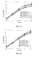
- FIG.3 includes schematic diagrams illustrating comparisons of performances between the transparent MU-MIMO and the non-transparent MU-MIMO with a full buffer traffic model, wherein the full buffer traffic model means that the data amount in a buffer is always full.
- FIG.3a shows the comparison of system throughputs when an MRC receiver is adopted
- FIG.3b shows the comparison of system throughputs when an IRC receiver is adopted.
- the IRC receiver since the DMRS port information of the co-scheduled UEs is unknown in the transparent MU-MIMO, the IRC receiver will use blind detection, e.g. always regards that a co-scheduled UE exists in the blind detection.
- Transparent case 3 can achieve the performance similar to the non-transparent MU-MIMO for not-high (low and middle) SNRs, but has a little bit performance loss for high SNRs due to impact of degradation of channel estimation accuracy. Furthermore, transparent case 1 has performance loss for all SNRs because of resource waste. Transparent case 2 has the best performance in low SNRs with low total rank because PDSCH puncturing is unnecessary, but there is performance loss for high SNRs due to PDSCH puncturing for high total rank.
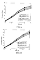
- FIG.4 shows comparisons of the system throughputs between the transparent MU-MIMO and the non-transparent MU-MIMO with an on-off traffic model.
- An on-off factor is 0.5.
- the on-off traffic model means that the data amount in the buffer is not always full and the state that the data amount in the buffer is full is intermittent.
- FIG.4a shows a comparison of system throughputs when an MRC receiver is adopted
- FIG.4b shows a comparison of system throughputs when an IRC receiver is adopted.
Abstract
Description
- The present invention relates to wireless communication techniques, and more particularly, to a method and system for Multi-User Multiple Input Multiple Output (MU-MIMO) transmission.
- From evaluation results on International Mobile Telecommunications Advanced (IMT-A) obtained by International Telecommunications Union-Radio communications (ITU-R), single-cell enhanced Multi-User MIMO (MU-MIMO) has been identified as an important technique for LTE Advanced (LTE-A) to improve system performance. In LTE Rel-8, Single-User MIMO (SU-MIMO) and MU-MIMO are supported by different transmission modes which are configured semi-statically by higher layer. And in LTE Rel-9, transparent MU-MIMO is used and up to rank 2 (i.e. Trank ≤2) transmission can be supported. Trank refers to the number of Demodulation Reference Signal (DMRS) ports which are actually allocated to UEs. Orthogonal Cover Code (OCC) is used for DMRS multiplexing. In LTE Rel-10, the transparent MU-MIMO has been further discussed so as to support a situation that Trank > 2. It should be noted that, the total number of DMRS ports N port , i.e. the number of DMRS ports available for the UEs, is fixed. When DMRS density is 12, Nport =4, and when DMRS density is 24, NPort =8. However, the total number of allocated DMRS ports Trank is not fixed. For example, when N port =8, Trank may be 2.
- The transparent MU-MIMO indicates that, for any UE participating in an MU-MIMO coordinated transmission, there is no difference between SU-MIMO and MU-MIMO transmission. Hereinafter, any UE participating in an MU-MIMO coordinated transmission is referred to as the ith UE. During PDSCH receiving, the ith UE only knows its own DMRS port information, e.g. the number of ports occupied by the i th UE and which ports are occupied by the i th UE, etc. However, the i th UE does not know DMRS port information of its co-scheduled UEs. For example, UE1, UE2 and UE3 are scheduled in a same Resource Block (RB). The three UEs form a coordinated transmission group, in which UE2 and UE3 are co-scheduled UEs of UE1 . During the transparent MU-MIMO transmission, UE1 cannot acquire the DMRS port information of the UE2 and the UE3. Correspondingly, non-transparent MU-MIMO indicates that, any UE in a group of UEs participating in the MU-MIMO coordinated transmission can know the DMRS port information of its co-scheduled UEs.
- Compared with the non-transparent MU-MIMO, the transparent MU-MIMO has some advantages and some performance loss at the same time. The advantages of the transparent MU-MIMO include:
- (1) High scheduling flexibility
The transparent MU-MIMO allows relative flexible scheduling, e.g., one UE can simultaneously use SU-MIMO and MU-MIMO on different subbands within one Transmission Time Interval (TTI). The scheduling flexibility is beneficial to the improvement of system performance. - (2) Low signaling overhead
In the transparent MU-MIMO, only same signaling as SU-MIMO is informed and there is no additional signaling about the co-scheduled UEs. - On the other hand, the transparent MU-MIMO could possibly bring some performance loss due to:
- (1) No effective support for advanced receiver
Advanced receiver, e.g., Interference Rejection Combining (IRC) receiver, can improve the system performance by cancelling the interference from co-scheduled UEs to the ith UE. But in the transparent MU-MIMO, since the ith UE does not know channel information even the existence of the co-scheduled UEs, effective IRC receiving can not be applied. - (2) Lack of DMRS density information
For LTE Rel-10, the total number of allocated DMRS ports will change within a range. Therefore, the DMRS density may be used to indicate DMRS port occupation situations of multiple UEs in the coordinated transmission group. More specifically, when the total number of allocated DMRS ports is not larger than 2, the DMRS density is 12 REs/RB. And when the total number of allocated DMRS ports is larger than 2 (any value from 3 to 8), the DMRS density is 24 REs/RB. In the transparent MU-MIMO, if the number of ports occupied by one UE is larger than 2, it indicates that the total number of allocated DMRS ports must be larger than 2. Therefore, the UE is able to know the DMRS density of the coordinated transmission group indirectly. But when the number of ports occupied by the UE is not larger than 2, the UE cannot know the DMRS density. The number of ports occupied by the UE refers to the number of DMRS ports allocated to the UE. In this case, at the UE side, collision between DMRS and PDSCH data will occur, otherwise, puncturing of PDSCH data is needed. The PDSCH data refers to user data of the UE. - In view of the above characteristics of the transparent MU-MIMO in wireless transmission, a detailed solution is required to provide the transparent MU-MIMO between a base station and the UE, so as to exert the advantages of the transparent MU-MIMO at most and avoid the performance loss at the same time.
- Embodiments of the present invention provide a method and system for MU-MIMO transmission, which improve system performance in the case that a coordinated transmission UE cannot know DMRS port information of its co-scheduled UEs.
- In order to achieve the above objective, the technical solution of the present invention is as follows:
- A method for MU-MIMO transmission includes:
- configuring, by a base station, Demodulation Reference Signal (DMRS) ports for coordinated transmission User Equipments (UEs) performing an MU-MIMO transmission, and mapping DMRS symbols and user data of each coordinated transmission UE onto each Resource Block (RB) according to the total number of allocated DMRS ports and configurations of the configured DMRS ports;
- transmitting, by the base station, DMRS port information of an i th UE of the coordinated transmission UEs to the ih UE, wherein i is a natural number; and
- receiving, by the ith UE, user data and DMRS symbols of the ith UE from each RB according to the DMRS port information of the i th UE.
- Preferably, the method further includes:
- dividing, by the base station, each RB into M*N Resource Elements (REs), and grouping the REs in each RB into a first DMRS symbol area, a second DMRS symbol area and a user data area, wherein M and N are natural numbers respectively.
- Preferably, the mapping the DMRS symbols and the user data onto each RB includes:
- mapping, by the base station, the user data of the th UE to the user data area; and if the total number of allocated DMRS ports is not larger than 2, mapping, by the base station, the DMRS symbols of the ith UE onto the first DMRS symbol area; if the total number of the allocated DMRS ports is larger than 2, mapping, by the base station, the DMRS symbols of the ith UE onto the first DMRS symbol area and/or the second DMRS symbol area.
- Preferably, the receiving the user data and the DMRS symbols of the i th UE from each RB by the i th UE according to the DMRS port information of then ith UE includes:
- receiving, by the ith UE, the user data from the user data area; and
- receiving, by the ith UE, the DMRS symbols of the ith UE from the first DMRS symbol area and/or the second DMRS symbol area according to the DMRS port information of the ith UE.
- Preferably, the mapping the DMRS symbols and the user data onto each RB includes:
- if it is determined that the total number of the allocated DMRS ports is not larger than 2, mapping, by the base station, the user data to the user data area and the second DMRS symbol area, and mapping the DMRS symbols to the first DMRS symbol area.
- Preferably, the receiving the user data and the DMRS symbols of the i th UE from each RB by the ith UE according to the DMRS port information of the i th UE includes:
- receiving, by then i th UE, the user data from the user data area and the second DMRS symbol area, and receiving the DMRS symbols of the ith UE from the first DMRS symbol area according to the DMRS port information of the ith UE.
- Preferably, the mapping the DMRS symbols and the user data onto each RB includes:
- if it is determined that the total number of the allocated DMRS ports is larger than 2 and OCC length is 2, if an index of a DMRS port configured for then ith UE is not larger than 1, and if the DMRS ports configured for all coordinated transmission UEs are continuous, mapping, by the base station, the user data onto the user data area and the second DMRS symbol area; mapping the DMRS symbols onto the first DMRS symbol area; then puncturing the user data in the second DMRS symbol area, and filling DMRS symbols of co-scheduled UEs into the second DMRS symbol area.
- Preferably, the receiving the user data and the DMRS symbols of the ith UE from each RB by the ith UE according to the DMRS port information of the ith UE includes:
- if the ith UE learns that the OCC length is 2 and determines that the index of the DMRS port occupied by the ith UE is not larger than 1 according to the DMRS port information of the ith UE, receiving, by the ith UE, first data from the user data area and the second DMRS symbol area and taking the first data as the user data, and receiving the DMRS symbols of the ith UE from the first DMRS symbol area.
- Preferably, the mapping the DMRS symbols and the user data onto each RB includes:
- if it is determined that the total number of the allocated DMRS ports is larger than 2 and OCC length is 2, and if the DMRS ports configured for all the coordinated transmission UEs are discontinuous, mapping, by the base station, the DMRS symbols to one of the first DMRS symbol area and the second DMRS symbol area according to the configurations of the configured DMRS ports, and mapping the user data onto the user data area and the other of the first DMRS symbol area and the second DMRS symbol area, puncturing the user data in the other of the first DMRS symbol area and the second DMRS symbol area, and filling DMRS symbols of co-scheduled UEs in the other of the first DMRS symbol area and the second DMRS symbol area.
- Preferably, the receiving the user data and the DMRS symbols of the ith UE from each RB by the ith UE according to the DMRS port information of the ith UE includes:
- learning, by the ith UE, that the OCC length is 2, receiving, by the ith UE, the DMRS symbols of the ith UE from one of the first DMRS symbol area and the second DMRS symbol area according to the DMRS port information of the ithUE, and receiving first data from the user data area and the other of the first DMRS symbol area and the second DMRS symbol area.
- Preferably, the mapping the DMRS symbols and the user data onto each RB includes:
- if it is determined that the total number of the allocated DMRS ports is larger than 2 and OCC length is 2, if an index of a DMRS port configured for ith UE is larger than 1 and if the DMRS ports configured for all coordinated transmission UEs are continuous, mapping, by the base station, the user data to the user data area, and mapping the DMRS symbols to the first DMRS symbol area and the second DMRS symbol area.
- Preferably, the receiving the user data and the DMRS symbols of the ith UE from each RB by the ith UE according to the DMRS port information of then ith UE includes:
- if the ith UE learns that the OCC length is 2 and determines that the index of the DMRS port configured for the ith UE is larger than 1 according to the DMRS port information of the ith UE, receiving, by the ithUE, the user data from the user data area, and receiving the DMRS symbols of the ith UE from the first DMRS symbol area and the second DMRS symbol area.
- Preferably, the mapping the DMRS symbols and the user data onto each RB includes:
- if it is determined that the total number of the allocated DMRS ports is larger than 2 and OCC length is 2, if an index of a DMRS port configured for then ith UE is not larger than 1 and if the DMRS ports configured for all the coordinated transmission UEs are continuous, mapping, by the base station, the user data onto the user data area and the second DMRS symbol area, mapping the DMRS symbols onto the first DMRS symbol area, and multiplexing DMRS symbols of co-scheduled UEs and the user data in the second DMRS symbol area.
- Preferably, the receiving the user data and the DMRS symbols of the ith UE from each RB by the ith UE according to the DMRS port information of the ith UE includes:
- if the ith UE learns that the OCC length is 2 and determines that the index of the DMRS port occupied by the ith UE is not larger than 1 according to the DMRS port information of then ith UE, receiving, by the ith UE, the DMRS symbols of the ith UE from the first DMRS symbol area, receiving the user data from the user data area, receiving first data from the second DMRS symbol area, and de-multiplexing the first data to obtain the user data according to a pre-coding vector.
- Preferably, the mapping the DMRS symbols and the user data onto each RB includes:
- if it is determined that the total number of the allocated DMRS ports is larger than 2 and OCC length is 2, and if the DMRS ports configured for all the coordinated transmission UEs are discontinuous, mapping, by the base station, the DMRS symbols to one of the first DMRS symbol area and the second DMRS symbol area, mapping the user data to the user data area and the other of the first DMRS symbol area and the second DMRS symbol area, and multiplexing DMRS symbols of co-scheduled UEs and the user data in the other of the first DMRS symbol area and the second DMRS symbol area.
- Preferably, the receiving the user data and the DMRS symbols of the ith UE from each RB by the ith UE according to the DMRS port information of the ith UE includes:
- if the ith UE learns that the OCC length is 2, receiving, by the ith UE, the DMRS symbols of the ith UE from one of the first DMRS symbol area and the second DMRS symbol area, receiving the user data from the user data area, receiving first data from the other of the first DMRS symbol area and the second DMRS symbol area, and de-multiplexing the first data to obtain the user data according to a pre-coding vector.
- Preferably, each RB is divided into 14* 12 REs;
- the first DMRS symbol area includes REs with m=6, 7, 13, 14 and n=1, 6, 11; the second DMRS symbol area includes REs with m=6, 7, 13,, 14 and n=2, 7, 12; the user data area includes REs other than the REs in the first DMRS symbol area, the REs in the second DMRS symbol area and REs allocated for signaling.
- A system for Multi-User Multiple Input Multiple Output (MU-MIMO) includes:
- a base station, adapted to configure Demodulation Reference Signal (DMRS) ports for coordinated transmission User Equipments (UEs) performing an MU-MIMO transmission, and map DMRS symbols and user data of each coordinated transmission UE onto each Resource Block (RB) according to the total number of allocated DMRS ports and configurations of the configured DMRS ports; transmit DMRS port information of any ith UE of the coordinated transmission UEs to the ith UE, wherein i is a natural number; and
- the ith UE, adapted to receive user data and DMRS symbols of the ith UE from each RB according to the DMRS port information of the ith UE.
- It can be seen from the above technical solution that, in the method for MU-MIMO transmission provided by the present invention, the base station side maps the user data and the DMRS symbols according to the total number of allocated DMRS ports. Furthermore, the base station maps the user data and the DMRS symbols to multiple REs of one RB according to a DMRS port allocation situation and an Orthogonal Cover Code (OCC) length of each coordinated transmission UE. Each coordinated transmission UE correctly receives its own DMRS symbols and the user data according to an assumed DMRS density and makes full use of its DMRS port information. Even if the assumed DMRS density is different from the actual DMRS density, the method provided by the present invention can still ensure the reception of the DMRS symbols of each coordinated transmission UE.
-
-
FIG.1 is a flowchart illustrating a method for MU-MIMO transmission according to an embodiment of the present invention. - FIC.2 is a schematic diagram illustrating distribution of a first DMRS symbol area, a second DMRS symbol area and a user data area in an RB according to an embodiment of the present invention.
-
FIG.3a and FIG.3b are schematic diagrams illustrating comparisons between performances of transparent MU-MIMO and non-transparent MU-MIMO with full buffer traffic. -
FIG.4a and FIG.4b are schematic diagrams illustrating comparisons between performances of transparent MU-MIMO and non-transparent MU-MIMO with on-off traffic. - The present invention will be described hereinafter in further detail with reference to accompanying drawings and embodiments to make the technical solution and merits therein clearer.
-
FIG.1 is a flowchart illustrating a method for MU-MIMO transmission according to an embodiment of the present invention. The method includes the following steps. -
Step 101, a base station configures DMRS ports for coordinated transmission UEs in an MU-MIMO transmission. -
Step 102, DRMS symbols and user data of each coordinated transmission UE are mapped to each RB according to the total number of allocated DMRS ports and the configured DMRS ports. -
Step 103, DMRS port information of the ith UE among the coordinated transmission UEs is transmitted to the ith UE, where i is a natural number and is within the range from 1 to the maximum number of DMRS ports. -
Step 104, then ith UE receives the user data and the DMRS symbols of the ith UE from each RB according to the DMRS port information of the ith UE. - In the above transparent MU-MIMO transmission, each UE participating in the coordinated transmission cannot know DMRS density information corresponding to the total number of allocated DMRS ports (total rank), hereinafter the total rank is denoted by Trank. Therefore, during the mapping of PDSCH at the base station side and the receiving at the UE side, there may be several cases as follows.
- Transparent case 1: whether Trank is larger than 2 or not, the base station will not fill user data in REs indicated by biases and REs indicated by dots. The REs indicated by biases belong to a first DMRS symbol area, the REs indicated by dots belong to a second DMRS symbol area, and except those allocated to signaling, the REs without filling belong to a user data area. In particular, the first DMRS symbol area includes REs with m=6, 7, 13, 14 and n=1, 6, 11. The second DMRS symbol area includes REs with m=6, 7, 13, 14 and n=2, 7, 12. Wherein m indicates a time index and n indicates frequency index. The division of the RB is not restricted to the manner shown in
FIG.2 . One RB may be divided into M*N REs, wherein M and N are both integers larger than 1. - When Trank > 2 (Trank = 3,4,5,6,7,8), the DRMS symbols occupy 24 REs. The above operation of the base station does not waste resources. When Trank ≤ 2 , only 12 Res are occupied by the DMRS symbols and the other 12 REs (i.e. the second DMRS symbol area) are null and not used for filling user data.
- Accordingly, the UE assumes that the DMRS density used by the base station side is 24 REs occupied per RB (i.e. 24 REs/RB). Therefore, the UE does not receive user data on these 24 REs. Since the base station side never fills user data in the second DMRS symbol area in any case, i.e. the second DMRS symbol area is filled with DMRS symbols or is null, the UE side need not consider the actual DMRS density. Certainly, the resource is wasted in case of the actual DMRS density of 12 REs/RB.
- It should be noted that, whether OCC length is 2 or 4, the
transparent case 1 is applicable. - Transparent case 2: the UE assumes that the base station side uses DMRS density of 12 REs/RB.
- (1) When Trank ≤ 2 , the base station side encodes and modulates the user data and the DMRS symbols in bits, and maps the user data and the DMRS symbols onto the REs of each RB. Since Trank ≤ 2 , the DMRS symbols occupy at most 12 REs filled with biases as shown in
FIG.2 . The other REs (i.e. the user data area and the second DMRS symbol area) in each RB are filled with the user data.
Accordingly, the ith UE may occupy Port-0 or Pot-1, or occupy both Port-0 and Port-1 at the same time. In other words, the DMRS density is exactly 12 REs/RB and the assumption of the UE is correct. During the receiving process, the UE obtains the DMRS symbols only from the 12 REs indicated by biases and obtains the user data from the other REs. - (2) When Trank > 2 and the OCC length is 2 (i.e. 4 ≥ Trank > 2 ), and when the ith UE occupies one or more REs indicated by biases
The base station side first fills the user data in the REs other than the 12 REs indicated by biases inFIG.2 , next punctures the user data in the 12 REs indicated by dots inFIG.2 and then fills the DMRS symbols of co-scheduled UEs in the 12 REs indicated by dots inFIG.2 , so as to avoid collision between the DMRS symbols and the user data.
During the receiving process, the ith UE learns that it occupies Port-0 or Port-1 or occupies both Port-0 and Port-1 at the same time according to the DMRS port information of the ith UE. In other words, the No. of the port occupied by the ith UE is not larger than 1. The ith UE obtains the DMRS symbols only from the 12 REs indicated by biases and obtains the user data from other REs. In this case, the ith UE also regards the DMRS symbols of the co-scheduled UEs recorded in the 12 REs indicated by dots as the user data of the ith UE. It should be noted that, all available DMRS ports are numbered from 0 to NPort -1.
As to a situation that DMRS ports configured for all coordinated transmission UEs are discontinuous, when it is determined that the total rank is larger than 2 and the OCC length is 2, the base station maps the DMRS symbols onto one of the first DMRS symbol area and the second DMRS symbol area according to the configurations of the configured DMRS ports, and maps the user data onto the other of the first DMRS symbol area and the second DMRS symbol area as well as onto the user data area, then punctures the user data in the other of the first DMRS symbol area and the second DMRS symbol area and fills the DMRS symbols of the co-scheduled UEs in the other of the first DMRS symbol area and the second DMRS symbol area.
Accordingly, the ith UE learns that the OCC length is 2, receives its own DMRS symbols from one of the first DMRS symbol area and the second DMRS symbol area according to the DMRS port information of the ith UE, and receives first data from the user data area and the other of the first DMRS symbol area and the second DMRS symbol area. - (3) When Trank > 2 and the OCC length is 2 (i.e. 4 ≥Trank > 2), and when the ith UE occupies one or more REs indicated by dots
The base station side maps the user data onto the user data area, and maps the DMRS symbols onto the first DMRS symbol area and the second DMRS symbol area.
Accordingly, the ith UE receives the user data from the user data area, and receives its own DMRS symbols from the first DMRS symbol area and the second DMRS symbol area. - Transparent case 3: similar to the
transparent case 2, the UE assumes that the base station side uses DMRS density of 12 REs/RB. The difference is that, when the actual DMRS density is 24 REs/RB, the base station side first fills the user data into REs other than the 12 REs indicated by biases inFIG.2 , and then multiplexes the DMRS symbols of the co-scheduled UEs and the user data in the 12 REs indicated by dots inFIG.2 . Although there may be collision between the user data of the ith UE and the DMRS symbols of the co-scheduled UEs in the above operation, the user data of the ith UE and the DMRS symbols of the co-scheduled UEs can be differentiated at the ith UE side because they use different pre-coding vectors. - As to a situation that the DMRS ports configured for all the coordinated transmission UEs are discontinuous, when it is determined that the total rank is larger than 2 and the OCC length is 2, the base station maps the DMRS symbols onto one of the first DMRS symbol area and the second DMRS symbol area according to the DMRS port configurations, and maps the user data onto the other of the first DMRS symbol area and the second DMRS symbol area as well as onto the user data area, and then multiplexes the DMRS symbols of the co-scheduled UEs and the user data in the other of the first DMRS symbol area and the second DMRS symbol area. For example, when DMRS symbols of the ith UE occupy the second DMRS symbol area, the user data will be mapped onto the first DMRS symbol area and the user data area.
- Accordingly, when learning that the OCC length is 2, then ith UE receives its own DMRS symbols from one of the first DMRS symbol area and the second DMRS symbol area according to the DMRS port information of the ith UE, receives the user data from the user data area, and receives first data from the other of the first DMRS symbol area and the second DMRS symbol area, de-multiplexes the first data to obtain the user data according to the pre-coding vector.
- Hereinafter, the performances of the transparent MU-MIMO and the non-transparent MU-MIMO are compared through simulation. Table 1 gives link level parameters used in the simulation. It is assumed that two OFDM symbols are used for the PDCCH, and the overhead for a common control channel is ignored. It is also assumed that DMRS density is 12 REs/RB for total rank 1-2 and 24 REs/RB for total rank 3-8.
Table 1 Simulation Parameters Carrier frequency 2 GHz Transmission bandwidth 10 MHz Subframe length 1 msec RB bandwidth 180 kHz (12 subcarriers) Subband bandwidth 1.08 MHz (6 RBs) Channel model Typical Urban, TU Spatial correlation between antennas Highly-correlated for Tx (coefficient 0.95) and uncorrelated for Rx Moving speed or Max. Doppler frequency 3 km/h (fD = 5.55 Hz) Number of eNodeB/UE antennas 4 (eNodeB), 2 (UE) Note: the antennas are co-polarization Dimensioning of MU- MIMO Rank 1 for each UE, up to 4 for total rank, and dynamic rank adaptation Scheduling algorithm Frequency-domain scheduling based on PF Traffic model Full buffer/ on-off traffic model with on-off factor of 0.5 Control delay on scheduling or AMC 4 msec HARQ Chase combination Round trip delay of HARQ 8 msec MCS set QPSK (R = 1/8 - 5/6) 16QAM (R = 1/2 - 5/6) 64QAM (R = 3/5 - 4/5) PMI feedback Wideband, 1 TTI; rank 1CQI feedback Subband, 1 TTI; rank 1Granularity of scheduling Subband, 1 TTI Codebook Household codebook as Rel-8 UE receiver assumption MRC/IRC -
FIG.3 includes schematic diagrams illustrating comparisons of performances between the transparent MU-MIMO and the non-transparent MU-MIMO with a full buffer traffic model, wherein the full buffer traffic model means that the data amount in a buffer is always full.FIG.3a shows the comparison of system throughputs when an MRC receiver is adopted andFIG.3b shows the comparison of system throughputs when an IRC receiver is adopted. As toFIG.3b , since the DMRS port information of the co-scheduled UEs is unknown in the transparent MU-MIMO, the IRC receiver will use blind detection, e.g. always regards that a co-scheduled UE exists in the blind detection. It can be seen fromFIG.3 that, whether the MRC receiver or the IRC receiver is adopted, the non-transparent MU-MIMO always has the best performance for almost all SNRs. But it should be noted that, the non-transparent MU-MIMO means larger signaling overhead.Transparent case 3 can achieve the performance similar to the non-transparent MU-MIMO for not-high (low and middle) SNRs, but has a little bit performance loss for high SNRs due to impact of degradation of channel estimation accuracy. Furthermore,transparent case 1 has performance loss for all SNRs because of resource waste.Transparent case 2 has the best performance in low SNRs with low total rank because PDSCH puncturing is unnecessary, but there is performance loss for high SNRs due to PDSCH puncturing for high total rank. -
FIG.4 shows comparisons of the system throughputs between the transparent MU-MIMO and the non-transparent MU-MIMO with an on-off traffic model. An on-off factor is 0.5. The on-off traffic model means that the data amount in the buffer is not always full and the state that the data amount in the buffer is full is intermittent. -
FIG.4a shows a comparison of system throughputs when an MRC receiver is adopted andFIG.4b shows a comparison of system throughputs when an IRC receiver is adopted. As can be seen, conclusions are similar to that of the full buffer traffic model. Certainly, due to reduction of total rank in case of finite buffer traffic, the gain of transparent MU-MIMO overnon-transparent case 3 is a little bit decreased because the gain oftransparent case 3 on increased PDSCH length due to multiplexing of PDSCH and DRMS symbols of co-scheduled UEs is reduced. In addition, the performance oftransparent case 1 becomes a little bit worse compared totransparent case 2. - The simulation results show the following:
- 1) Compared with the non-transparent MU-MIMO, the transparent MU-MIMO implemented by adopting the transparent case 3 (i.e. multiplexing the PDSCH of a certain UE and the DMRS symbols of co-scheduled UEs) can achieve similar performance for low SNRs but has a little bit performance loss for high SNRs.
- 2) For the transparent MU-MIMO, always assuming the DMRS density of 24 REs/RB (i.e. the transparent case 1) at the UE side, or always assuming the DMRS density of 12 REs/RB with PDSCH puncturing (i.e. the transparent case 2) has a little bit performance loss.
- The foregoing descriptions are only preferred embodiments of this invention and are not for use in limiting the protection scope thereof. Any changes and modifications can be made by those skilled in the art without departing from the spirit of this invention and therefore should be covered within the protection scope as set by the appended claims.
Claims (18)
- A method for Multi-User Multiple Input Multiple Output (MU-MIMO), comprising:configuring, by a base station, Demodulation Reference Signal (DMRS) ports for coordinated transmission User Equipments (UEs) performing an MU-MIMO transmission, and mapping DMRS symbols and user data of each coordinated transmission UE onto each Resource Block (RB) according to the total number of allocated DMRS ports and configurations of the configured DMRS ports;transmitting, by the base station, DMRS port information of an ith UE of the coordinated transmission UEs to the ith UE, wherein i is a natural number; andreceiving, by the ith UE, user data and DMRS symbols of the ith UE from each RB according to the DMRS port information of the ith UE.
- The method of claim 1, further comprising:dividing, by the base station, each RB into M*N Resource Elements (REs), and grouping the REs in each RB into a first DMRS symbol area, a second DMRS symbol area and a user data area, wherein M and N are natural numbers respectively.
- The method of claim 2, wherein the mapping the DMRS symbols and the user data onto each RB comprises:mapping, by the base station, the user data of the ith UE onto the user data area;
andif the total number of the allocated DMRS ports is not larger than 2, mapping, by the base station, the DMRS symbols of the ith UE onto the first DMRS symbol area; if the total number of the allocated DMRS ports is larger than 2, mapping, by the base station, the DMRS symbols of the ith UE onto the first DMRS symbol area and/or the second DMRS symbol area. - The method of claim 3, wherein the receiving the user data and the DMRS symbols of the ith UE from each RB by the ith UE according to the DMRS port information of the ith UE comprises:receiving, by the ith UE, the user data from the user data area; andreceiving, by then ith UE, the DMRS symbols of then ith UE from the first DMRS symbol area and/or the second DMRS symbol area according to the DMRS port information of then ith UE.
- The method of claim 2, wherein the mapping the DMRS symbols and the user data onto each RB comprises:if it is determined that the total number of the allocated DMRS ports is not larger than 2, mapping, by the base station, the user data to the user data area and the second DMRS symbol area, and mapping the DMRS symbols to the first DMRS symbol area.
- The method of claim 5, wherein the receiving the user data and the DMRS symbols of the ith UE from each RB by then ith UE according to the DMRS port information of the ith UE comprises:receiving, by the ith UE, the user data from the user data area and the second DMRS symbol area, and receiving the DMRS symbols of then ith UE from the first DMRS symbol area according to the DMRS port information of the ith UE.
- The method of claim 2, wherein the mapping the DMRS symbols and the user data onto each RB comprises:if it is determined that the total number of the allocated DMRS ports is larger than 2 and Orthogonal Cover Code (OCC) length is 2, if an index of a DMRS port configured for the ith UE is not larger than 1, and if the DMRS ports configured for all coordinated transmission UEs are continuous, mapping, by the base station, the user data onto the user data area and the second DMRS symbol area; mapping the DMRS symbols onto the first DMRS symbol area; then puncturing the user data in the second DMRS symbol area, and filling DMRS symbols of co-scheduled UEs into the second DMRS symbol area.
- The method of claim 7, wherein the receiving the user data and the DMRS symbols of the ith UE from each RB by then ith UE according to the DMRS port information of the ith UE comprises:if the ith UE learns that the OCC length is 2 and determines that the index of the DMRS port occupied by the ith UE is not larger than 1 according to the DMRS port information of the ith UE, receiving, by the ith UE, first data from the user data area and the second DMRS symbol area and taking the first data as the user data, and receiving the DMRS symbols of the ith UE from the first DMRS symbol area.
- The method of claim 2, wherein the mapping the DMRS symbols and the user data onto each RB comprises:if it is determined that the total number of the allocated DMRS ports is larger than 2 and OCC length is 2, and if the DMRS ports configured for all the coordinated transmission UEs are discontinuous, mapping, by the base station, the DMRS symbols to one of the first DMRS symbol area and the second DMRS symbol area according to the configurations of the configured DMRS ports, and mapping the user data onto the user data area and the other of the first DMRS symbol area and the second DMRS symbol area, puncturing the user data in the other of the first DMRS symbol area and the second DMRS symbol area, and filling DMRS symbols of co-scheduled UEs in the other of the first DMRS symbol area and the second DMRS symbol area.
- The method of claim 9, wherein the receiving the user data and the DMRS symbols of the ith UE from each RB by the ith UE according to the DMRS port information of the ith UE comprises:learning, by the ith UE, that the OCC length is 2, receiving, by the ith UE, the DMRS symbols of the ith UE from one of the first DMRS symbol area and the second DMRS symbol area according to the DMRS port information of the ith UE, and receiving first data from the user data area and the other of the first DMRS symbol area and the second DMRS symbol area.
- The method of claim 2, wherein the mapping the DMRS symbols and the user data onto each RB comprises:if it is determined that the total number of the allocated DMRS ports is larger than 2 and OCC length is 2, if an index of a DMRS port configured for ith UE is larger than 1 and if the DMRS ports configured for all coordinated transmission UEs are continuous, mapping, by the base station, the user data to the user data area, and mapping the DMRS symbols to the first DMRS symbol area and the second DMRS symbol area.
- The method of claim 11, wherein the receiving the user data and the DMRS symbols of the ith UE from each RB by then ith UE according to the DMRS port information of then ith UE comprises:if the ith UE learns that the OCC length is 2 and determines that the index of the DMRS port configured for the ith UE is larger than 1 according to the DMRS port information of the ith UE, receiving, by then ith UE, the user data from the user data area, and receiving the DMRS symbols of the ith UE from the first DMRS symbol area and the second DMRS symbol area.
- The method of claim 2, wherein the mapping the DMRS symbols and the user data onto each RB comprises:if it is determined that the total number of the allocated DMRS ports is larger than 2 and OCC length is 2, if an index of a DMRS port configured for the ith UE is not larger than 1 and if the DMRS ports configured for all the coordinated transmission UEs are continuous, mapping, by the base station, the user data onto the user data area and the second DMRS symbol area, mapping the DMRS symbols onto the first DMRS symbol area, and multiplexing DMRS symbols of co-scheduled UEs and the user data in the second DMRS symbol area.
- The method of claim 13, wherein the receiving the user data and the DMRS symbols of the ith UE from each RB by the ith UE according to the DMRS port information of the ith UE comprises:if the ith UE learns that the OCC length is 2 and determines that the index of the DMRS port occupied by the ith UE is not larger than 1 according to the DMRS port information of the ith UE, receiving, by the ith UE, the DMRS symbols of the ith UE from the first DMRS symbol area, receiving the user data from the user data area, receiving first data from the second DMRS symbol area, and de-multiplexing the first data to obtain the user data according to a pre-coding vector.
- The method of claim 2, wherein the mapping the DMRS symbols and the user data onto each RB comprises:if it is determined that the total number of the allocated DMRS ports is larger than 2 and OCC length is 2, and if the DMRS ports configured for all the coordinated transmission UEs are discontinuous, mapping, by the base station, the DMRS symbols to one of the first DMRS symbol area and the second DMRS symbol area, mapping the user data to the user data area and the other of the first DMRS symbol area and the second DMRS symbol area, and multiplexing DMRS symbols of co-scheduled UEs and the user data in the other of the first DMRS symbol area and the second DMRS symbol area.
- The method of claim 15, wherein the receiving the user data and the DMRS symbols of the ith UE from each RB by the ith UE according to the DMRS port information of the ith UE comprises:if the ith UE learns that the OCC length is 2, receiving, by the ith UE, the DMRS symbols of then ith UE from one of the first DMRS symbol area and the second DMRS symbol area, receiving the user data from the user data area, receiving first data from the other of the first DMRS symbol area and the second DMRS symbol area, and de-multiplexing the first data to obtain the user data according to a pre-coding vector.
- The method of anyone of claims 2-16, wherein each RB is divided into 14* 12 REs;
the first DMRS symbol area includes REs with m=6, 7, 13, 14 and n=1, 6, 11; the second DMRS symbol area includes REs with m=6, 7, 13, 14 and n=2, 7, 12; the user data area includes REs other than the REs in the first DMRS symbol area, the REs in the second DMRS symbol area and REs allocated for signaling. - A system for Multi-User Multiple Input Multiple Output (MU-MIMO), comprising:a base station, adapted to configure Demodulation Reference Signal (DMRS) ports for coordinated transmission User Equipments (UEs) performing an MU-MIMO transmission, and map DMRS symbols and user data of each coordinated transmission UE onto each Resource Block (RB) according to the total number of allocated DMRS ports and configurations of the configured DMRS ports; transmit DMRS port information of an ith UE of the coordinated transmission UEs to the ith UE, wherein i is a natural number; andthe ith UE, adapted to receive user data and DMRS symbols of then ith UE from each RB according to the DMRS port information of the ith UE.
Applications Claiming Priority (1)
| Application Number | Priority Date | Filing Date | Title |
|---|---|---|---|
| CN201010004504.2A CN102122985B (en) | 2010-01-11 | 2010-01-11 | MU-MIMO (Multi-User Multi-Input Multi-Output) transmission method |
Publications (3)
| Publication Number | Publication Date |
|---|---|
| EP2346201A2 true EP2346201A2 (en) | 2011-07-20 |
| EP2346201A3 EP2346201A3 (en) | 2016-10-19 |
| EP2346201B1 EP2346201B1 (en) | 2021-07-21 |
Family
ID=44072560
Family Applications (1)
| Application Number | Title | Priority Date | Filing Date |
|---|---|---|---|
| EP10193186.3A Active EP2346201B1 (en) | 2010-01-11 | 2010-11-30 | Method and system for MU-MIMO transmission |
Country Status (3)
| Country | Link |
|---|---|
| EP (1) | EP2346201B1 (en) |
| JP (1) | JP5669540B2 (en) |
| CN (1) | CN102122985B (en) |
Cited By (8)
| Publication number | Priority date | Publication date | Assignee | Title |
|---|---|---|---|---|
| WO2014089110A1 (en) * | 2012-12-03 | 2014-06-12 | Intel Corporation | Notification of receiver capabilities |
| US8917690B2 (en) | 2012-01-30 | 2014-12-23 | Broadcom Corporation | Method and apparatus for providing enhanced interference suppression |
| WO2017196398A1 (en) * | 2016-05-13 | 2017-11-16 | Intel Corporation | Qcl (quasi co-location) for dm-rs (demodulation reference signal) antenna ports for comp (coordinated multi-point) |
| CN108111207A (en) * | 2017-11-10 | 2018-06-01 | 北京邮电大学 | Information transferring method and device |
| WO2018182244A1 (en) * | 2017-03-25 | 2018-10-04 | 엘지전자 주식회사 | Method for assigning ptrs for phase noise removal in wireless communication system, and device therefor |
| WO2018201879A1 (en) * | 2017-05-05 | 2018-11-08 | 华为技术有限公司 | Communications method, related device and system |
| CN109906572A (en) * | 2016-08-12 | 2019-06-18 | 瑞典爱立信有限公司 | With the uplink control signaling on the PUSCH for shortening Transmission Time Interval |
| US10756861B2 (en) | 2017-05-05 | 2020-08-25 | Huawei Technologies Co., Ltd. | Communication method, and related device and system |
Families Citing this family (13)
| Publication number | Priority date | Publication date | Assignee | Title |
|---|---|---|---|---|
| CN102170624B (en) * | 2011-03-29 | 2014-07-16 | 电信科学技术研究院 | Demodulating reference signal configuration indication, transmission and control signaling detection method and equipment |
| KR20130014960A (en) * | 2011-08-01 | 2013-02-12 | 주식회사 팬택 | Transmitting method of reference signal, transmission apparatus thereof, receiving method of reference signal, reception apparatus thereof |
| RU2608773C2 (en) * | 2011-11-16 | 2017-01-24 | Самсунг Электроникс Ко., Лтд. | Method and device for control information transmitting in wireless communication systems |
| CN106877978B (en) * | 2011-12-31 | 2021-01-26 | 中兴通讯股份有限公司 | Control channel detection method and device |
| CN105027481B (en) | 2013-03-03 | 2018-01-23 | Lg 电子株式会社 | The method that control information is received on EPDCCH |
| CN104995975B (en) * | 2013-06-19 | 2019-06-28 | 华为技术有限公司 | A kind of method and apparatus of interference coordination |
| CN104393965B (en) * | 2014-11-21 | 2017-11-21 | 西安电子科技大学 | User collaboration transmission method in multi-user wireless network |
| CN106559196B (en) * | 2015-09-25 | 2019-10-22 | 华为技术有限公司 | A kind of method and device of pilot tone distribution |
| CN107113272B (en) * | 2015-09-25 | 2019-11-26 | 华为技术有限公司 | A kind of method for mapping resource and device |
| CN106856426B (en) * | 2015-12-09 | 2019-07-19 | 电信科学技术研究院 | A kind of DMRS indicating means, terminal and base station |
| CN106888062B (en) * | 2015-12-10 | 2020-04-10 | 电信科学技术研究院 | CQI estimation and SINR determination method and related equipment |
| CN107181579A (en) * | 2016-03-11 | 2017-09-19 | 北京信威通信技术股份有限公司 | A kind of descending DMRS resource multiplexing methods |
| CN107889222B (en) * | 2016-09-29 | 2022-03-08 | 华为技术有限公司 | Signal transmission method, terminal device, network device and communication system |
Family Cites Families (2)
| Publication number | Priority date | Publication date | Assignee | Title |
|---|---|---|---|---|
| WO2009099306A1 (en) * | 2008-02-07 | 2009-08-13 | Samsung Electronics Co., Ltd. | Methods and apparatus to allocate acknowledgement channels |
| CN101621492A (en) * | 2009-08-14 | 2010-01-06 | 中兴通讯股份有限公司 | Resource determining method of special demodulation data reference signal |
-
2010
- 2010-01-11 CN CN201010004504.2A patent/CN102122985B/en active Active
- 2010-11-30 EP EP10193186.3A patent/EP2346201B1/en active Active
- 2010-12-02 JP JP2010269438A patent/JP5669540B2/en active Active
Non-Patent Citations (1)
| Title |
|---|
| None |
Cited By (15)
| Publication number | Priority date | Publication date | Assignee | Title |
|---|---|---|---|---|
| US8917690B2 (en) | 2012-01-30 | 2014-12-23 | Broadcom Corporation | Method and apparatus for providing enhanced interference suppression |
| US10715193B2 (en) | 2012-12-03 | 2020-07-14 | Apple Inc. | Notification of receiver capabilities |
| WO2014089110A1 (en) * | 2012-12-03 | 2014-06-12 | Intel Corporation | Notification of receiver capabilities |
| WO2017196398A1 (en) * | 2016-05-13 | 2017-11-16 | Intel Corporation | Qcl (quasi co-location) for dm-rs (demodulation reference signal) antenna ports for comp (coordinated multi-point) |
| CN109906572B (en) * | 2016-08-12 | 2022-02-08 | 瑞典爱立信有限公司 | Uplink control signaling on PUSCH with shortened transmission time interval |
| US11863329B2 (en) | 2016-08-12 | 2024-01-02 | Telefonaktiebolaget Lm Ericsson (Publ) | Uplink control signaling on PUSCH with shortened transmission time interval (TTI) |
| CN109906572A (en) * | 2016-08-12 | 2019-06-18 | 瑞典爱立信有限公司 | With the uplink control signaling on the PUSCH for shortening Transmission Time Interval |
| WO2018182244A1 (en) * | 2017-03-25 | 2018-10-04 | 엘지전자 주식회사 | Method for assigning ptrs for phase noise removal in wireless communication system, and device therefor |
| US11469869B2 (en) | 2017-03-25 | 2022-10-11 | Lg Electronics Inc. | Method for assigning PTRS for phase noise removal in wireless communication system, and device therefor |
| CN110463130A (en) * | 2017-03-25 | 2019-11-15 | Lg电子株式会社 | The method and its equipment for the PTRS that assignment is eliminated for phase noise in a wireless communication system |
| US10965415B2 (en) | 2017-03-25 | 2021-03-30 | Lg Electronics Inc. | Method for assigning PTRS for phase noise removal in wireless communication system, and device therefor |
| US10756861B2 (en) | 2017-05-05 | 2020-08-25 | Huawei Technologies Co., Ltd. | Communication method, and related device and system |
| WO2018201879A1 (en) * | 2017-05-05 | 2018-11-08 | 华为技术有限公司 | Communications method, related device and system |
| CN108111207B (en) * | 2017-11-10 | 2021-04-23 | 北京邮电大学 | Information transmission method and device |
| CN108111207A (en) * | 2017-11-10 | 2018-06-01 | 北京邮电大学 | Information transferring method and device |
Also Published As
| Publication number | Publication date |
|---|---|
| CN102122985B (en) | 2015-04-08 |
| CN102122985A (en) | 2011-07-13 |
| EP2346201B1 (en) | 2021-07-21 |
| JP2011142617A (en) | 2011-07-21 |
| EP2346201A3 (en) | 2016-10-19 |
| JP5669540B2 (en) | 2015-02-12 |
Similar Documents
| Publication | Publication Date | Title |
|---|---|---|
| EP2346201B1 (en) | Method and system for MU-MIMO transmission | |
| US11019526B2 (en) | Antenna port mapping for demodulation reference signals | |
| JP7170636B2 (en) | PT-RS configuration according to scheduling parameters | |
| KR101715939B1 (en) | Method and apparatus for channel state information feedback | |
| KR101715397B1 (en) | Apparatus and method for transmitting reference signal in wireless communication system | |
| US9729218B2 (en) | Method and apparatus for transmitting signal in wireless communication system | |
| CN102106097B (en) | Method for allocating PHICH and generating reference signal in system using single-user MIMO based on multiple codewords when transmitting uplink | |
| KR101776097B1 (en) | Method and system for mapping uplink control information | |
| KR101755038B1 (en) | Apparatus and method of transmitting reference signal in wireless communication system | |
| EP2540006B1 (en) | Method and system for indicating an enabled transport block | |
| CN110224727A (en) | Data transmission method for uplink, signaling method, apparatus and system | |
| KR20110038994A (en) | Method of receiving and transmitting multi-user control channels in wireless communication system with multiple antennas and apparatus thereof | |
| WO2011085509A1 (en) | Layer-to dm rs port mapping for lte-advanced | |
| CN109217992B (en) | Transmission method of phase tracking reference signal, communication equipment and storage medium | |
| CN110120859A (en) | A kind of user equipment that be used to wirelessly communicate, the method and apparatus in base station | |
| CN104754537A (en) | Method and device for transmitting and receiving network-assisted signals | |
| CN111512682A (en) | Method and device used in user equipment and base station for wireless communication | |
| US8812814B2 (en) | User equipment buffer management in multiple-input multiple-output communication systems | |
| CN111447680B (en) | Method and device used in user equipment and base station for wireless communication |
Legal Events
| Date | Code | Title | Description |
|---|---|---|---|
| PUAI | Public reference made under article 153(3) epc to a published international application that has entered the european phase |
Free format text: ORIGINAL CODE: 0009012 |
|
| AK | Designated contracting states |
Kind code of ref document: A2 Designated state(s): AL AT BE BG CH CY CZ DE DK EE ES FI FR GB GR HR HU IE IS IT LI LT LU LV MC MK MT NL NO PL PT RO RS SE SI SK SM TR |
|
| AX | Request for extension of the european patent |
Extension state: BA ME |
|
| PUAL | Search report despatched |
Free format text: ORIGINAL CODE: 0009013 |
|
| AK | Designated contracting states |
Kind code of ref document: A3 Designated state(s): AL AT BE BG CH CY CZ DE DK EE ES FI FR GB GR HR HU IE IS IT LI LT LU LV MC MK MT NL NO PL PT RO RS SE SI SK SM TR |
|
| AX | Request for extension of the european patent |
Extension state: BA ME |
|
| RIC1 | Information provided on ipc code assigned before grant |
Ipc: H04L 5/00 20060101AFI20160912BHEP |
|
| STAA | Information on the status of an ep patent application or granted ep patent |
Free format text: STATUS: REQUEST FOR EXAMINATION WAS MADE |
|
| 17P | Request for examination filed |
Effective date: 20170228 |
|
| STAA | Information on the status of an ep patent application or granted ep patent |
Free format text: STATUS: EXAMINATION IS IN PROGRESS |
|
| 17Q | First examination report despatched |
Effective date: 20180615 |
|
| STAA | Information on the status of an ep patent application or granted ep patent |
Free format text: STATUS: EXAMINATION IS IN PROGRESS |
|
| GRAP | Despatch of communication of intention to grant a patent |
Free format text: ORIGINAL CODE: EPIDOSNIGR1 |
|
| STAA | Information on the status of an ep patent application or granted ep patent |
Free format text: STATUS: GRANT OF PATENT IS INTENDED |
|
| INTG | Intention to grant announced |
Effective date: 20210202 |
|
| RIN1 | Information on inventor provided before grant (corrected) |
Inventor name: SHE, XIAOMING Inventor name: YUN, XIANG Inventor name: ZHANG, BIJUN Inventor name: CHEN, LAN Inventor name: ZHU, JIANCHI |
|
| GRAS | Grant fee paid |
Free format text: ORIGINAL CODE: EPIDOSNIGR3 |
|
| GRAA | (expected) grant |
Free format text: ORIGINAL CODE: 0009210 |
|
| STAA | Information on the status of an ep patent application or granted ep patent |
Free format text: STATUS: THE PATENT HAS BEEN GRANTED |
|
| AK | Designated contracting states |
Kind code of ref document: B1 Designated state(s): AL AT BE BG CH CY CZ DE DK EE ES FI FR GB GR HR HU IE IS IT LI LT LU LV MC MK MT NL NO PL PT RO RS SE SI SK SM TR |
|
| REG | Reference to a national code |
Ref country code: GB Ref legal event code: FG4D |
|
| REG | Reference to a national code |
Ref country code: CH Ref legal event code: EP |
|
| REG | Reference to a national code |
Ref country code: DE Ref legal event code: R096 Ref document number: 602010067289 Country of ref document: DE |
|
| REG | Reference to a national code |
Ref country code: AT Ref legal event code: REF Ref document number: 1413605 Country of ref document: AT Kind code of ref document: T Effective date: 20210815 |
|
| REG | Reference to a national code |
Ref country code: IE Ref legal event code: FG4D |
|
| REG | Reference to a national code |
Ref country code: LT Ref legal event code: MG9D |
|
| REG | Reference to a national code |
Ref country code: NL Ref legal event code: MP Effective date: 20210721 |
|
| REG | Reference to a national code |
Ref country code: AT Ref legal event code: MK05 Ref document number: 1413605 Country of ref document: AT Kind code of ref document: T Effective date: 20210721 |
|
| PG25 | Lapsed in a contracting state [announced via postgrant information from national office to epo] |
Ref country code: HR Free format text: LAPSE BECAUSE OF FAILURE TO SUBMIT A TRANSLATION OF THE DESCRIPTION OR TO PAY THE FEE WITHIN THE PRESCRIBED TIME-LIMIT Effective date: 20210721 Ref country code: SE Free format text: LAPSE BECAUSE OF FAILURE TO SUBMIT A TRANSLATION OF THE DESCRIPTION OR TO PAY THE FEE WITHIN THE PRESCRIBED TIME-LIMIT Effective date: 20210721 Ref country code: LT Free format text: LAPSE BECAUSE OF FAILURE TO SUBMIT A TRANSLATION OF THE DESCRIPTION OR TO PAY THE FEE WITHIN THE PRESCRIBED TIME-LIMIT Effective date: 20210721 Ref country code: AT Free format text: LAPSE BECAUSE OF FAILURE TO SUBMIT A TRANSLATION OF THE DESCRIPTION OR TO PAY THE FEE WITHIN THE PRESCRIBED TIME-LIMIT Effective date: 20210721 Ref country code: BG Free format text: LAPSE BECAUSE OF FAILURE TO SUBMIT A TRANSLATION OF THE DESCRIPTION OR TO PAY THE FEE WITHIN THE PRESCRIBED TIME-LIMIT Effective date: 20211021 Ref country code: NO Free format text: LAPSE BECAUSE OF FAILURE TO SUBMIT A TRANSLATION OF THE DESCRIPTION OR TO PAY THE FEE WITHIN THE PRESCRIBED TIME-LIMIT Effective date: 20211021 Ref country code: NL Free format text: LAPSE BECAUSE OF FAILURE TO SUBMIT A TRANSLATION OF THE DESCRIPTION OR TO PAY THE FEE WITHIN THE PRESCRIBED TIME-LIMIT Effective date: 20210721 Ref country code: PT Free format text: LAPSE BECAUSE OF FAILURE TO SUBMIT A TRANSLATION OF THE DESCRIPTION OR TO PAY THE FEE WITHIN THE PRESCRIBED TIME-LIMIT Effective date: 20211122 Ref country code: RS Free format text: LAPSE BECAUSE OF FAILURE TO SUBMIT A TRANSLATION OF THE DESCRIPTION OR TO PAY THE FEE WITHIN THE PRESCRIBED TIME-LIMIT Effective date: 20210721 Ref country code: FI Free format text: LAPSE BECAUSE OF FAILURE TO SUBMIT A TRANSLATION OF THE DESCRIPTION OR TO PAY THE FEE WITHIN THE PRESCRIBED TIME-LIMIT Effective date: 20210721 Ref country code: ES Free format text: LAPSE BECAUSE OF FAILURE TO SUBMIT A TRANSLATION OF THE DESCRIPTION OR TO PAY THE FEE WITHIN THE PRESCRIBED TIME-LIMIT Effective date: 20210721 |
|
| PG25 | Lapsed in a contracting state [announced via postgrant information from national office to epo] |
Ref country code: PL Free format text: LAPSE BECAUSE OF FAILURE TO SUBMIT A TRANSLATION OF THE DESCRIPTION OR TO PAY THE FEE WITHIN THE PRESCRIBED TIME-LIMIT Effective date: 20210721 Ref country code: LV Free format text: LAPSE BECAUSE OF FAILURE TO SUBMIT A TRANSLATION OF THE DESCRIPTION OR TO PAY THE FEE WITHIN THE PRESCRIBED TIME-LIMIT Effective date: 20210721 Ref country code: GR Free format text: LAPSE BECAUSE OF FAILURE TO SUBMIT A TRANSLATION OF THE DESCRIPTION OR TO PAY THE FEE WITHIN THE PRESCRIBED TIME-LIMIT Effective date: 20211022 |
|
| REG | Reference to a national code |
Ref country code: DE Ref legal event code: R097 Ref document number: 602010067289 Country of ref document: DE |
|
| PG25 | Lapsed in a contracting state [announced via postgrant information from national office to epo] |
Ref country code: DK Free format text: LAPSE BECAUSE OF FAILURE TO SUBMIT A TRANSLATION OF THE DESCRIPTION OR TO PAY THE FEE WITHIN THE PRESCRIBED TIME-LIMIT Effective date: 20210721 |
|
| PLBE | No opposition filed within time limit |
Free format text: ORIGINAL CODE: 0009261 |
|
| STAA | Information on the status of an ep patent application or granted ep patent |
Free format text: STATUS: NO OPPOSITION FILED WITHIN TIME LIMIT |
|
| PG25 | Lapsed in a contracting state [announced via postgrant information from national office to epo] |
Ref country code: SM Free format text: LAPSE BECAUSE OF FAILURE TO SUBMIT A TRANSLATION OF THE DESCRIPTION OR TO PAY THE FEE WITHIN THE PRESCRIBED TIME-LIMIT Effective date: 20210721 Ref country code: SK Free format text: LAPSE BECAUSE OF FAILURE TO SUBMIT A TRANSLATION OF THE DESCRIPTION OR TO PAY THE FEE WITHIN THE PRESCRIBED TIME-LIMIT Effective date: 20210721 Ref country code: RO Free format text: LAPSE BECAUSE OF FAILURE TO SUBMIT A TRANSLATION OF THE DESCRIPTION OR TO PAY THE FEE WITHIN THE PRESCRIBED TIME-LIMIT Effective date: 20210721 Ref country code: EE Free format text: LAPSE BECAUSE OF FAILURE TO SUBMIT A TRANSLATION OF THE DESCRIPTION OR TO PAY THE FEE WITHIN THE PRESCRIBED TIME-LIMIT Effective date: 20210721 Ref country code: CZ Free format text: LAPSE BECAUSE OF FAILURE TO SUBMIT A TRANSLATION OF THE DESCRIPTION OR TO PAY THE FEE WITHIN THE PRESCRIBED TIME-LIMIT Effective date: 20210721 Ref country code: AL Free format text: LAPSE BECAUSE OF FAILURE TO SUBMIT A TRANSLATION OF THE DESCRIPTION OR TO PAY THE FEE WITHIN THE PRESCRIBED TIME-LIMIT Effective date: 20210721 |
|
| 26N | No opposition filed |
Effective date: 20220422 |
|
| PG25 | Lapsed in a contracting state [announced via postgrant information from national office to epo] |
Ref country code: MC Free format text: LAPSE BECAUSE OF FAILURE TO SUBMIT A TRANSLATION OF THE DESCRIPTION OR TO PAY THE FEE WITHIN THE PRESCRIBED TIME-LIMIT Effective date: 20210721 |
|
| REG | Reference to a national code |
Ref country code: CH Ref legal event code: PL |
|
| PG25 | Lapsed in a contracting state [announced via postgrant information from national office to epo] |
Ref country code: LU Free format text: LAPSE BECAUSE OF NON-PAYMENT OF DUE FEES Effective date: 20211130 Ref country code: IT Free format text: LAPSE BECAUSE OF FAILURE TO SUBMIT A TRANSLATION OF THE DESCRIPTION OR TO PAY THE FEE WITHIN THE PRESCRIBED TIME-LIMIT Effective date: 20210721 Ref country code: BE Free format text: LAPSE BECAUSE OF NON-PAYMENT OF DUE FEES Effective date: 20211130 |
|
| REG | Reference to a national code |
Ref country code: BE Ref legal event code: MM Effective date: 20211130 |
|
| PG25 | Lapsed in a contracting state [announced via postgrant information from national office to epo] |
Ref country code: IE Free format text: LAPSE BECAUSE OF NON-PAYMENT OF DUE FEES Effective date: 20211130 |
|
| PG25 | Lapsed in a contracting state [announced via postgrant information from national office to epo] |
Ref country code: FR Free format text: LAPSE BECAUSE OF NON-PAYMENT OF DUE FEES Effective date: 20211130 |
|
| PG25 | Lapsed in a contracting state [announced via postgrant information from national office to epo] |
Ref country code: HU Free format text: LAPSE BECAUSE OF FAILURE TO SUBMIT A TRANSLATION OF THE DESCRIPTION OR TO PAY THE FEE WITHIN THE PRESCRIBED TIME-LIMIT; INVALID AB INITIO Effective date: 20101130 Ref country code: CY Free format text: LAPSE BECAUSE OF FAILURE TO SUBMIT A TRANSLATION OF THE DESCRIPTION OR TO PAY THE FEE WITHIN THE PRESCRIBED TIME-LIMIT Effective date: 20210721 |
|
| P01 | Opt-out of the competence of the unified patent court (upc) registered |
Effective date: 20230510 |
|
| PG25 | Lapsed in a contracting state [announced via postgrant information from national office to epo] |
Ref country code: LI Free format text: LAPSE BECAUSE OF NON-PAYMENT OF DUE FEES Effective date: 20220630 Ref country code: CH Free format text: LAPSE BECAUSE OF NON-PAYMENT OF DUE FEES Effective date: 20220630 |
|
| PGFP | Annual fee paid to national office [announced via postgrant information from national office to epo] |
Ref country code: GB Payment date: 20231123 Year of fee payment: 14 |
|
| PGFP | Annual fee paid to national office [announced via postgrant information from national office to epo] |
Ref country code: DE Payment date: 20231121 Year of fee payment: 14 |