EP2345884A2 - Hardness test method, hardness tester, and computer-readable storage medium storing program - Google Patents
Hardness test method, hardness tester, and computer-readable storage medium storing program Download PDFInfo
- Publication number
- EP2345884A2 EP2345884A2 EP11150288A EP11150288A EP2345884A2 EP 2345884 A2 EP2345884 A2 EP 2345884A2 EP 11150288 A EP11150288 A EP 11150288A EP 11150288 A EP11150288 A EP 11150288A EP 2345884 A2 EP2345884 A2 EP 2345884A2
- Authority
- EP
- European Patent Office
- Prior art keywords
- indenter
- work load
- hardness
- indent
- indentation
- Prior art date
- Legal status (The legal status is an assumption and is not a legal conclusion. Google has not performed a legal analysis and makes no representation as to the accuracy of the status listed.)
- Granted
Links
Images






Classifications
-
- G—PHYSICS
- G01—MEASURING; TESTING
- G01N—INVESTIGATING OR ANALYSING MATERIALS BY DETERMINING THEIR CHEMICAL OR PHYSICAL PROPERTIES
- G01N3/00—Investigating strength properties of solid materials by application of mechanical stress
- G01N3/40—Investigating hardness or rebound hardness
- G01N3/42—Investigating hardness or rebound hardness by performing impressions under a steady load by indentors, e.g. sphere, pyramid
-
- G—PHYSICS
- G01—MEASURING; TESTING
- G01N—INVESTIGATING OR ANALYSING MATERIALS BY DETERMINING THEIR CHEMICAL OR PHYSICAL PROPERTIES
- G01N2203/00—Investigating strength properties of solid materials by application of mechanical stress
- G01N2203/0058—Kind of property studied
- G01N2203/0076—Hardness, compressibility or resistance to crushing
- G01N2203/0078—Hardness, compressibility or resistance to crushing using indentation
- G01N2203/0082—Indentation characteristics measured during load
-
- G—PHYSICS
- G01—MEASURING; TESTING
- G01N—INVESTIGATING OR ANALYSING MATERIALS BY DETERMINING THEIR CHEMICAL OR PHYSICAL PROPERTIES
- G01N2203/00—Investigating strength properties of solid materials by application of mechanical stress
- G01N2203/02—Details not specific for a particular testing method
- G01N2203/0202—Control of the test
- G01N2203/0212—Theories, calculations
- G01N2203/0218—Calculations based on experimental data
-
- G—PHYSICS
- G01—MEASURING; TESTING
- G01N—INVESTIGATING OR ANALYSING MATERIALS BY DETERMINING THEIR CHEMICAL OR PHYSICAL PROPERTIES
- G01N2203/00—Investigating strength properties of solid materials by application of mechanical stress
- G01N2203/02—Details not specific for a particular testing method
- G01N2203/026—Specifications of the specimen
- G01N2203/0286—Miniature specimen; Testing on microregions of a specimen
Definitions
- the present invention relates to a hardness test method, a hardness tester, and a computer-readable storage medium storing a program.
- an indentation hardness tester such as a Vickers hardness tester, for evaluating and measuring the hardness of a sample on the basis of an indent formed by indenting an indenter, loaded with a predetermined load thereon, on a surface of the sample has been known (see, for example, Japanese Patent Application Laid-Open Publication No. 2005-326169 ).
- nanoindentation instrumentation indentation test
- F a force loaded on an indenter
- indentation depth a displacement quantity of an indenter
- the nanoindentation is effective as an evaluation method of a material the indent observation of which is difficult by a primary factor, such as a small size of an indent. Consequently, the nanoindentation is noticed to be suitable for the evaluation of the mechanical properties of a plastic and a thin film material, which are construction materials indispensable for various machines and structures.
- indentation hardness H IT For the nanoindentation, International Standard ISO (International Organization for Standardization) 14577 regulates the parameter of hardness called indentation hardness H IT , and the cases of using the indentation hardness H IT for the evaluation of a thin film material and the like have recently increased.
- the indentation hardness H IT is treated as a value having a correlation with the Vickers hardness.
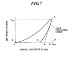
- FIG. 7 is a schematic diagram of an F-h curve.
- the ordinate axis thereof indicates a test force F, and the abscissa axis thereof indicates an indentation depth h.
- the indentation hardness H IT is defined by the following formula (1) as a value obtained by dividing the maximum test force (set test force) Fmax by the contact projected area Ap(hc) of a sample of an indenter at the time of the maximum indentation.
- H IT Fmax / Ap hc
- the contact projected area Ap(hc) is expressed as the following formula (2) from the geometric shape of the Berkovich indenter.
- Ap hc 23.96 ⁇ hc 2
- hc is called contact depth, and is expressed by the following formula (3) by using the maximum indentation depth hmax, and an intersection point hr of a tangential line of the initial part of a load unloading curve and an indentation depth axis.
- Hc hmax - 0.75 ⁇ hmax - hr
- the aforesaid analysis method of the indentation hardness H IT regulated by the ISO 14577 is a technique proposed by Oliver and Phart, and it was ascertained by their research that there was a correlation between the indentation hardness H IT and the Vickers hardness HV.
- the samples that they used in their research were ones each having a strong tendency of plastic behavior, such as a metal, and ones each expressing a deformation in which an elastic deformation and a plastic deformation were mixed, i.e. ones clearly expressing elastoplastic behavior, such as fused silica, and they did not examine the materials each having a strong tendency of showing the elastic behavior, such as a rubber material and an amorphous material.
- the nanoindentation including also the materials each having a strong tendency of showing the elastic behavior as objects, it is difficult to treat the indentation hardness H IT regulated in the ISO 14577 as being equivalent to the Vickers hardness HV.
- FIG. 8 is a diagram showing a relation between the indentation hardness H IT and the Vickers hardness HV of copper, beryllium copper (Cu-Be), tool steel (SK85), fused silica, acrylic resin, polypropylene (PP), and a diamond-like carbon (DLC) film.
- the ordinate axis thereof indicates the indentation hardness H IT
- the abscissa axis thereof indicates the Vickers hardness HV.
- the straight line in FIG. 8 expresses the indentation hardness H IT and the Vickers hardness HV by the following formula (4) by using a coefficient C.
- H IT C 1 ⁇ HV
- the straight line in FIG. 8 expresses the formula (4) when the coefficient C 1 is set to 1.25.
- some causes such as a point of using a projected area, not a surface area, for the calculation of indentation hardness H IT ; causes of errors peculiar to the nanoindentation, such as a tip shape of an indenter and a surface detection error; and the like, can be considered.
- the values of the indentation hardness H IT and the Vickers hardness HV of the samples other than the DLC film have a correlation, although the values are not equal.
- the values of the indentation hardness H IT and the Vickers hardness HV of the DLC film greatly deviate from the straight line, and the fact indicates that the treatment of the indentation hardness H IT as being equivalent to the Vickers hardness HV in the regulation of the ISO 14577 has a problem for the DLC film.
- the technique for obtaining a value corresponding to the Vickers hardness HV in the nanoindentation is not established in the case where the rubber material, the amorphous material, or the like is used as a sample.
- a hardness test method which hardness test method includes the steps of:
- the sample is made of a material selected from the group consisting of a diamondlike carbon, a silicon rubber, and a natural rubber.
- a hardness tester for forming an indent by indenting a surface of a sample with an indenter loaded with a predetermined load
- hardness tester includes:
- a computer-readable storage medium which computer-readable storage medium stores a program for making a computer function as:
- awork load by plastic deformation Wp
- HVe estimation of Vickers hardness
- a work load by plastic deformation is a value having a correlation with Vickers hardness independent of the type of a sample
- an estimation (HVe) of the Vickers hardness which estimation is a value corresponding to the Vickers hardness (HV) can be obtained in nanoindentation including materials showing remarkable elastic behavior, such as a rubber material and an amorphous material, as objects.
- a hardness tester 100 of the present embodiment is an instrumented indentation test machine capable of continuously monitoring a test force to be given to an indenter 3 and an indentation depth of the indenter 3.
- the hardness tester 100 of the present embodiment can use, for example, a DLC, a silicon rubber, a natural rubber, and the like as a sample S. That is, the hardness tester 100 can measure an evaporated film; a thin film of a semiconductor material or the like; a surface treated layer; various plastics; various rubbers; microfilaments; brittle materials, such as a glass and a ceramic; micro-electronic parts, and the like.
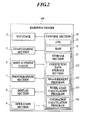
- the hardness tester 100 is equipped with a hardness tester main body 1, to which, for example, a control section 10 and each constituent member are provided to be arranged therein as shown in FIGs. 1 and 2 .
- the tester main body 1 is composed of an XYZ stage 2 to move the sample S in X, Y, and Z directions, a load lever 4 including the indenter 3 forming an indent on the sample S at one end thereof, a load loading section 5 to load (give) a predetermined load (test force) to the load lever 4, a displacement gauge 6 to detect a displacement quantity of the indenter 3, a photographing section 7 to photograph an indent or the like formed on the surface of the sample S, a display section 8, an operation section 9, and the like.
- the XYZ stage 2 is configured to move into the X, Y, and Z directions (i.e. horizontal direction and vertical direction) in conformity with a control signal input from the control section 10, and the sample S is adapted in such a way that the position thereof to the indenter 3 is adjusted by the movements thereof into front, back, right, left, upper, and lower directions by the XYZ stage 2.
- the XYZ stage 2 holds the sample S on the sample hold stand 2a lest the sample S placed on the top surface thereof should shifts during test measurement.
- the indenter 3 is an indenter used for hardness tests by indent formation, such as, Berkovich, Vickers, Knoop, and Brinell hardness tests.
- indent formation such as, Berkovich, Vickers, Knoop, and Brinell hardness tests.
- the load lever 4 is, for example, formed in almost a rod, and is fixed on a pedestal at almost the central part through a cross spring 4a.
- the indenter 3 is provided, which indenter 3 is provided in a freely touchable and detachable state to the sample S from above the sample S placed on the hold stand 2a and is pressed against the surface of the sample S to form an indent on the surface of the sample S.
- a force coil 5a constituting the load loading section 5, is provided.
- the load loading section 5 is, for example, a force motor, and is composed of the force coil 5a attached to the load lever 4, a fixed magnet 5b fixed to be opposed to the force coil 5a, and the like.
- the load loading section 5 rotates the load lever 4 by using a force as a drive force which force is generated by the electromagnetic induction generated by the magnetic field generated by the fixed magnet 5b in a gap of the load loading section 5 and the current flowing through the force coil 5a set in the gap in conformity with a control signal input from the control section 10. Consequently, the end of the load lever 4 on the side of the indenter 3 inclines downward, and the indenter 3 is indented on the sample S.
- the displacement gauge 6 is, for example, a capacitance type displacement sensor, and is composed of a movable pole plate 6a provided to the end of the load lever 4 on the side of the indenter 3, a fixed pole plate 6b fixed to be opposed to the movable pole plate 6a, and the like.
- the displacement gauge 6 for example, detects a change of the electrostatic capacity between the movable pole plate 6a and the fixed pole plate 6b, and then detects the displacement quantity by which the indenter 3 has moved at the time of forming an indent on the sample S (the indentation depth when the indenter 3 is indented into the sample S). The displacement gauge 6 thereby outputs a displacement signal based on the detected displacement quantity to the control section 10.
- the displacement gauge 6 is not limited to this type, but, for example, an optical displacement sensor or an eddy current displacement sensor may be used.
- the photographing section 7 is, for example, equipped with a camera and the like, and, for example, photographs an indent and the like formed on the surface of the sample S by the indenter 3 on the sample hold stand 2a in conformity with a control signal input from the control section 10.
- the display section 8 is, for example, a liquid display panel, and performs display processing of a surface image of the sample S photographed by the photographing section 7, various test results, and the like in conformity with a control signal input from the control section 10.
- the operation section 9 is, for example, an operation key group, such as a keyboard. When the operation section is operated by a user, the operation section outputs an operation signal accompanying the operation to the control section 10.
- the operation section 9 may be equipped with the other operation devices, such as a pointing device, such as a mouse and a touch panel, and a remote controller.
- the operation section 9 is operated in the case where a user performs an instruction input for performing a hardness test of the sample S, in the case where the user sets a test force, i.e. a load, to be loaded on the indenter 3, and in the other cases.
- a test force i.e. a load
- the control section 10 is composed of a central processing unit (CPU) 11, a random access memory (RAM) 12, a storage section 13, and the like, and is connected to the XYZ stage 2, the load loading section 5, the displacement gauge 6, the photographing section 7, the display section 8, the operation section 9, and the like through a system bus and the like.
- CPU central processing unit
- RAM random access memory
- the CPU 11 for example, performs various pieces of control processing in conformity with various processing programs for a hardness tester, stored in the storage section 13.
- the RAM 12 is provided with, for example, a program storage region for expanding a processing program to be executed by the CPU 11 and the like; a data storage region for storing input data, a processing result generated at the time of the execution of a processing program, and the like.
- the storage section 13 stores, for example, a system program executable in the hardness tester 100, various processing programs executable on the system program, the data to be used at the time of executing the various processing programs, the data of various processing results of the operation processing by the CPU 11, and the like.
- the programs are stored in the storage section 13 in the form of computer readable program codes.
- the storage section 13 stores, for example, a coefficient data storage section 131, a measurement program 132, a work load calculation program 133, an estimation calculation program 134, and the like.
- the coefficient data storage section 131 stores, for example, a coefficient K, which has been set and registered in advance by a user.
- the coefficient K is a predetermined constant satisfying a formula (6) to be described later, and is obtained by a user beforehand and is previously registered.
- the measurement program 132 is, for example, a program for enabling the CPU 11 to realize the function of detecting the displacement quantity of the indenter 3 and the test force loaded on the indenter 3 at the time of forming an indent to measure an indentation curve.
- the CPU 11 when the CPU 11 receives, for example, an input of an operation signal instructing the performance of measurement from the operation section 9, the CPU 11 controls the load loading section 5 to give a predetermined test force to the sample S placed on the sample hold stand 2a. Then, the CPU 11, for example, continuously measures an indentation depth on the sample S of the indenter 3 at the time of forming the indent, and a test force at the time of forming the indent, and measures a test force-indentation depth curve (indentation curve) as shown in FIG. 3 .
- the CPU 11 when the sample S is placed on the sample hold stand 2a and an operation signal is input, the CPU 11 outputs a control signal to the load loading section 5, and rotates the load lever 4 by using a force generated by electromagnetic induction of a magnetic field generated in the gap by the fixed magnet 5b of the load loading section 5 and a current flowing through the force coil 5a set in the gap, as a drive force.
- the end of the load lever 4 on the side of the indenter 3 inclines downward, and the indenter 3 forms an indent on the sample S.
- the load to be loaded on the indenter 3 is gradually increased until the test force reaches a set maximum test force (load loading step).
- the test force loaded on the indenter 3 is increased as shown in a load loading curve of FIG. 3 at the load loading step, and thereby the indentation depth of the indenter 3 to the sample S also increases.
- the CPU 11 judges that the load loaded on the indenter 3 reaches the maximum test force, the CPU 11 controls the supply quantity of the current to the drive coil to operate the load loading section 5, and thereby gradually decreases the load loaded on the indenter 3 (load unloading step).
- load unloading step the test force loaded on the indenter 3 is decreased as shown in the load unloading curve of FIG. 3 , and the indent depth of the indenter 3 to the sample S is also decreased.
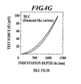
- FIGs. 4A-4G severally show an example of the indentation curves of the results of the measurements of copper, beryllium copper (Cu-Be), tool steel (SK85), fused silica, acrylic resin, polypropylene (PP), and a DLC film.
- Cu-Be beryllium copper
- SK85 tool steel
- fused silica acrylic resin
- PP polypropylene
- the CPU 11 functions as a measurement section by executing the measurement program 132.
- the work load calculation program 133 is, for example, a program for enabling the CPU 11 to realize the function of calculating the work load by plastic deformation Wp from the area of the indentation curve obtained by the execution of the measurement program 132.
- the mechanical work load (Wtotal: hereinafter referred to as Wt) generated during the indentation of the indenter 3 to the sample S, a work load (Welastic: hereinafter referred to as We) generated by the elastic deformation occupying the mechanical work load (Wt), and the work load by plastic deformation Wp can be obtained from the indentation curve as follows.
- Wt an area of a part enclosed by a curve passing through the points B and G, and a point H
- Wp an area of a part enclosed by a curve passing through the points B, G, and J
- We an area of a part enclosed by a curve passing through the points J and G, and a point H
- each work (Wt, Wp, We), i.e. the area of each part, is expressed by the sum of the product of a test force and an indentation depth in a minute interval of the indentation depth as the following formula (5).
- W ⁇ Fdh
- the CPU 11 executes the operation of the formula (5) by executing the work load calculation program 133 to calculate the area enclosed by the curve passing through the points B, G, and J in the indentation curve, i.e. the work load by plastic deformation Wp.
- the CPU 11 functions as a work load calculation section by executing the work load calculation program 133.
- the estimation calculation program 134 is, for example, a program for enabling the CPU 11 to realize the function of calculating an estimate value (HVestimation: hereinafter referred to HVe) of the Vickers hardness by using the work load (Wp) calculated by the execution of the work load calculation program 133 and the previously determined coefficient K in conformity with the following formula (6).
- HVe K / Wp 2
- the CPU 11 calculates the estimation (HVe) of the Vickers hardness by executing the operation of the formula (6) by using the work load by plastic deformation Wp calculated by the operation of the formula (5), and the coefficient K previously set and registered in the coefficient data storage section 131.
- the CPU 11 functions as an estimation calculation section by executing the estimation calculation program 134.
- FIG. 5 is a diagram showing a relation between the work load by plastic deformation Wp and the Vickers hardness HV values obtained by analyzing the indentation curve of FIGs. 4A-4G .
- the ordinate axis indicates the work load by plastic deformation Wp
- the abscissa axis indicates the Vickers hardness HV.
- the straight line of FIG. 5 expresses the work load by plastic deformation Wp and the Vickers hardness HV with the formula (8) by using the coefficient K.
- FIG. 6 is a flow chart showing a hardness test method by the hardness tester 100.
- Step S1 the CPU 11 judges whether or not a user has instructed to perform the hardness test of the sample S by an operation of the operation section 9.
- Step S1: No the CPU 11 repeats the processing at Step S1.
- Step S1 the CPU 11 judges that the user has instructed (Step S1: Yes)
- the CPU 11 measures an indentation curve by executing the measurement program 132 at the succeeding Step S2.
- Step S3 the CPU 11 calculates the work load by plastic deformation Wp form the indentation curve by executing the work load calculation program 133.
- Step S4 the CPU 11 calculates the estimation HVe of the Vickers hardness HV by using the work load by plastic deformation Wp and the previously determined coefficient K by executing the estimation calculation program 134, and ends the present processing.
- the estimation HVe of the Vickers hardness HV which is a value corresponding to the Vickers hardness HV, can be obtained in nanoindentation including the materials expressing remarkable elastic behavior, such as a rubber material and an amorphous material, as objects.
- the sample S is made of a diamondlike carbon, a silicon rubber, or a natural rubber.
- the hardness tester 100 can measure an evaporated film; a thin film made of a semiconductor material or the like; a surface treated layer; various plastics; various rubbers; brittle materials, such as a microfilament, a glass, and a ceramic; micro electronic parts; and the like.
- the hardness tester may be configured to move the indenter axis into the axial direction thereof by a drive force generated by supplying a drive current to the drive coil.
Landscapes
- Physics & Mathematics (AREA)
- Health & Medical Sciences (AREA)
- Life Sciences & Earth Sciences (AREA)
- Chemical & Material Sciences (AREA)
- Analytical Chemistry (AREA)
- Biochemistry (AREA)
- General Health & Medical Sciences (AREA)
- General Physics & Mathematics (AREA)
- Immunology (AREA)
- Pathology (AREA)
- Investigating Strength Of Materials By Application Of Mechanical Stress (AREA)
Abstract
Description
- The present invention relates to a hardness test method, a hardness tester, and a computer-readable storage medium storing a program.
- Conventionally, an indentation hardness tester, such as a Vickers hardness tester, for evaluating and measuring the hardness of a sample on the basis of an indent formed by indenting an indenter, loaded with a predetermined load thereon, on a surface of the sample has been known (see, for example, Japanese Patent Application Laid-Open Publication No.
2005-326169 - Moreover, a test method called nanoindentation (instrumentation indentation test) has been known, which method continuously measures a test force (a force loaded on an indenter) F and an indentation depth (a displacement quantity of an indenter) h to obtain a mechanical property of a material by analyzing an obtained indentation curve (F-h curve) in an indentation process in place of the observation of an indent formed after indentation, (see, for example, Japanese Patent Application Laid-Open Publication No.
2009-47427 - The nanoindentation is effective as an evaluation method of a material the indent observation of which is difficult by a primary factor, such as a small size of an indent. Consequently, the nanoindentation is noticed to be suitable for the evaluation of the mechanical properties of a plastic and a thin film material, which are construction materials indispensable for various machines and structures.
- For the nanoindentation, International Standard ISO (International Organization for Standardization) 14577 regulates the parameter of hardness called indentation hardness HIT, and the cases of using the indentation hardness HIT for the evaluation of a thin film material and the like have recently increased. The indentation hardness HIT is treated as a value having a correlation with the Vickers hardness.
- Here, the analysis method of the indentation hardness HIT that is regulated by the ISO 14577 is shown.
-
FIG. 7 is a schematic diagram of an F-h curve. The ordinate axis thereof indicates a test force F, and the abscissa axis thereof indicates an indentation depth h. - The indentation hardness HIT is defined by the following formula (1) as a value obtained by dividing the maximum test force (set test force) Fmax by the contact projected area Ap(hc) of a sample of an indenter at the time of the maximum indentation.

- Then, for example, the contact projected area Ap(hc) is expressed as the following formula (2) from the geometric shape of the Berkovich indenter.

- Moreover, hc is called contact depth, and is expressed by the following formula (3) by using the maximum indentation depth hmax, and an intersection point hr of a tangential line of the initial part of a load unloading curve and an indentation depth axis.

- The aforesaid analysis method of the indentation hardness HIT regulated by the ISO 14577 is a technique proposed by Oliver and Phart, and it was ascertained by their research that there was a correlation between the indentation hardness HIT and the Vickers hardness HV.
- However, the samples that they used in their research were ones each having a strong tendency of plastic behavior, such as a metal, and ones each expressing a deformation in which an elastic deformation and a plastic deformation were mixed, i.e. ones clearly expressing elastoplastic behavior, such as fused silica, and they did not examine the materials each having a strong tendency of showing the elastic behavior, such as a rubber material and an amorphous material. In the nanoindentation including also the materials each having a strong tendency of showing the elastic behavior as objects, it is difficult to treat the indentation hardness HIT regulated in the ISO 14577 as being equivalent to the Vickers hardness HV.
- For example,
FIG. 8 is a diagram showing a relation between the indentation hardness HIT and the Vickers hardness HV of copper, beryllium copper (Cu-Be), tool steel (SK85), fused silica, acrylic resin, polypropylene (PP), and a diamond-like carbon (DLC) film. The ordinate axis thereof indicates the indentation hardness HIT, and the abscissa axis thereof indicates the Vickers hardness HV. - The straight line in
FIG. 8 expresses the indentation hardness HIT and the Vickers hardness HV by the following formula (4) by using a coefficient C.
- To put it concretely, the straight line in
FIG. 8 expresses the formula (4) when the coefficient C1 is set to 1.25. In addition, as the reasons why the coefficient C1 is not 1 (HIT ≠ HV), for example, some causes, such as a point of using a projected area, not a surface area, for the calculation of indentation hardness HIT; causes of errors peculiar to the nanoindentation, such as a tip shape of an indenter and a surface detection error; and the like, can be considered. In any event, it can be said that the values of the indentation hardness HIT and the Vickers hardness HV of the samples other than the DLC film have a correlation, although the values are not equal. - On the other hand, the values of the indentation hardness HIT and the Vickers hardness HV of the DLC film greatly deviate from the straight line, and the fact indicates that the treatment of the indentation hardness HIT as being equivalent to the Vickers hardness HV in the regulation of the ISO 14577 has a problem for the DLC film.
- That is, the technique for obtaining a value corresponding to the Vickers hardness HV in the nanoindentation is not established in the case where the rubber material, the amorphous material, or the like is used as a sample.
- It is an object of the present invention to provide a hardness test method, a hardness tester, and a computer-readable storage medium storing a program that can obtain an estimation of Vickers hardness, which estimation is a value corresponding to the Vickers hardness, in nanoindentation.
- In order to achieve the object, according to a first aspect of the present invention, a hardness test method is provided which hardness test method includes the steps of:
- forming an indent by indenting a surface of a sample with an indenter loaded with a predetermined load and detecting a displacement quantity of the indenter and a test force loaded on the indenter at a time of forming the indent to measure an indentation curve;
- calculating a work load by plastic deformation (Wp) from an area of an indentation curve obtained by the step of forming the indent; and
- calculating an estimation (HVe) of Vickers hardness by using the work load (Wp), calculated at the step of calculating the work load, and a previously determined coefficient K in conformity with

- Preferably, the sample is made of a material selected from the group consisting of a diamondlike carbon, a silicon rubber, and a natural rubber.
- According to a second aspect of the present invention, a hardness tester for forming an indent by indenting a surface of a sample with an indenter loaded with a predetermined load is provided which hardness tester includes:
- a measurement section to measure an indentation curve by detecting a displacement quantity of the indenter and a test force loaded on the indenter at a time of forming the indent;
- a work load calculation section to calculate a work load by plastic deformation (Wp) from an area of an indentation curve obtained by the measurement section; and
- an estimation calculation section to calculate an estimation (HVe) of Vickers hardness by using the work load (Wp), calculated by the work load calculation section, and a previously determined coefficient K in conformity with

- According to a third aspect of the present invention, a computer-readable storage medium is provided which computer-readable storage medium stores a program for making a computer function as:
- a measurement section to measure an indentation curve by forming an indent by indenting a surface of a sample with an indenter loaded with a predetermined load, and by detecting a displacement quantity of the indenter and a test force loaded on the indenter at a time of forming the indent;
- a work load calculation section to calculate a work load by plastic deformation (Wp) from an area of an indentation curve obtained by the measurement section; and
- an estimation calculation section to calculate an estimation (HVe) of Vickers hardness by using the work load (Wp), calculated by the work load calculation section, and a previously determined coefficient K in conformity with

- According to the present invention, after measuring an indentation curve, awork load by plastic deformation (Wp) is calculated from an area of the indentation curve, and an estimation (HVe) of Vickers hardness is calculated by using the calculated work load (Wp) and a previously determined coefficient K in conformity with a relational formula: HVe = (K/Wp)2.
- Because a work load by plastic deformation (Wp) is a value having a correlation with Vickers hardness independent of the type of a sample, an estimation (HVe) of the Vickers hardness, which estimation is a value corresponding to the Vickers hardness (HV) can be obtained in nanoindentation including materials showing remarkable elastic behavior, such as a rubber material and an amorphous material, as objects.
- Examples of hardness testers and methods will now be described with reference to the accompanying drawings, in which:-
-
FIG. 1 is a schematic view showing a hardness tester according to an embodiment of the present invention; -
FIG. 2 is a block diagram showing a control configuration of the hardness tester ofFIG. 1 ; -
FIG. 3 is a diagram for describing a method of calculating a work load by plastic deformation Wp; -
FIG. 4A is an example of an indentation curve obtained by measuring copper; -
FIG. 4B is anexample of an indentation curve obtained by measuring beryllium copper; -
FIG. 4C is an example of an indentation curve obtained by measuring tool steel; -
FIG. 4D is an example of an indentation curve obtained by measuring fused silica; -
FIG. 4E is an example of an indentation curve obtained by measuring an acrylic resin; -
FIG. 4F is an example of an indentation curve obtained by measuring a polypropylene; -
FIG. 4G is an example of an indentation curve obtained by measuring a DLC film; -
FIG. 5 is a diagram showing a relation between a work load by plastic deformation Wp and Vickers hardness HV; -
FIG. 6 is a flow chart for describing a hardness test method by the hardness tester ofFIG. 1 ; -
FIG. 7 is a schematic diagram showing an indentation curve; and -
FIG. 8 is a diagram showing a relation between indentation hardness HIT and Vickers hardness HV. - In the following, ahardness tester and a hardness test method according to an embodiment of the present invention will be described in detail with reference to the accompanying drawings.
- A
hardness tester 100 of the present embodiment is an instrumented indentation test machine capable of continuously monitoring a test force to be given to anindenter 3 and an indentation depth of theindenter 3. - Moreover, the
hardness tester 100 of the present embodiment can use, for example, a DLC, a silicon rubber, a natural rubber, and the like as a sample S. That is, thehardness tester 100 can measure an evaporated film; a thin film of a semiconductor material or the like; a surface treated layer; various plastics; various rubbers; microfilaments; brittle materials, such as a glass and a ceramic; micro-electronic parts, and the like. - The
hardness tester 100 is equipped with a hardness testermain body 1, to which, for example, acontrol section 10 and each constituent member are provided to be arranged therein as shown inFIGs. 1 and2 . The testermain body 1 is composed of anXYZ stage 2 to move the sample S in X, Y, and Z directions, aload lever 4 including theindenter 3 forming an indent on the sample S at one end thereof, aload loading section 5 to load (give) a predetermined load (test force) to theload lever 4, adisplacement gauge 6 to detect a displacement quantity of theindenter 3, a photographingsection 7 to photograph an indent or the like formed on the surface of the sample S, adisplay section 8, anoperation section 9, and the like. - The
XYZ stage 2 is configured to move into the X, Y, and Z directions (i.e. horizontal direction and vertical direction) in conformity with a control signal input from thecontrol section 10, and the sample S is adapted in such a way that the position thereof to theindenter 3 is adjusted by the movements thereof into front, back, right, left, upper, and lower directions by theXYZ stage 2. - Moreover, the
XYZ stage 2 holds the sample S on thesample hold stand 2a lest the sample S placed on the top surface thereof should shifts during test measurement. - The
indenter 3 is an indenter used for hardness tests by indent formation, such as, Berkovich, Vickers, Knoop, and Brinell hardness tests. When theindenter 3 is indented on the surface of the sample S by being loaded with a predetermined load, theindenter 3 forms an indent (impression) on the surface of the sample S. - The
load lever 4 is, for example, formed in almost a rod, and is fixed on a pedestal at almost the central part through across spring 4a. - At one end of the
load lever 4, theindenter 3 is provided, which indenter 3 is provided in a freely touchable and detachable state to the sample S from above the sample S placed on thehold stand 2a and is pressed against the surface of the sample S to form an indent on the surface of the sample S. - Moreover, at the other end of the
load lever 4, aforce coil 5a, constituting theload loading section 5, is provided. - The
load loading section 5 is, for example, a force motor, and is composed of theforce coil 5a attached to theload lever 4, afixed magnet 5b fixed to be opposed to theforce coil 5a, and the like. - The
load loading section 5, for example, rotates theload lever 4 by using a force as a drive force which force is generated by the electromagnetic induction generated by the magnetic field generated by the fixedmagnet 5b in a gap of theload loading section 5 and the current flowing through theforce coil 5a set in the gap in conformity with a control signal input from thecontrol section 10. Consequently, the end of theload lever 4 on the side of theindenter 3 inclines downward, and theindenter 3 is indented on the sample S. - The
displacement gauge 6 is, for example, a capacitance type displacement sensor, and is composed of amovable pole plate 6a provided to the end of theload lever 4 on the side of theindenter 3, a fixedpole plate 6b fixed to be opposed to themovable pole plate 6a, and the like. - The
displacement gauge 6, for example, detects a change of the electrostatic capacity between themovable pole plate 6a and the fixedpole plate 6b, and then detects the displacement quantity by which theindenter 3 has moved at the time of forming an indent on the sample S (the indentation depth when theindenter 3 is indented into the sample S). Thedisplacement gauge 6 thereby outputs a displacement signal based on the detected displacement quantity to thecontrol section 10. - In addition, although the capacitance type displacement sensor has been illustrated as the
displacement gauge 6, thedisplacement gauge 6 is not limited to this type, but, for example, an optical displacement sensor or an eddy current displacement sensor may be used. - The photographing
section 7 is, for example, equipped with a camera and the like, and, for example, photographs an indent and the like formed on the surface of the sample S by theindenter 3 on thesample hold stand 2a in conformity with a control signal input from thecontrol section 10. - The
display section 8 is, for example, a liquid display panel, and performs display processing of a surface image of the sample S photographed by the photographingsection 7, various test results, and the like in conformity with a control signal input from thecontrol section 10. - The
operation section 9 is, for example, an operation key group, such as a keyboard. When the operation section is operated by a user, the operation section outputs an operation signal accompanying the operation to thecontrol section 10. In addition, theoperation section 9 may be equipped with the other operation devices, such as a pointing device, such as a mouse and a touch panel, and a remote controller. - The
operation section 9 is operated in the case where a user performs an instruction input for performing a hardness test of the sample S, in the case where the user sets a test force, i.e. a load, to be loaded on theindenter 3, and in the other cases. - The
control section 10 is composed of a central processing unit (CPU) 11, a random access memory (RAM) 12, astorage section 13, and the like, and is connected to theXYZ stage 2, theload loading section 5, thedisplacement gauge 6, the photographingsection 7, thedisplay section 8, theoperation section 9, and the like through a system bus and the like. - The
CPU 11, for example, performs various pieces of control processing in conformity with various processing programs for a hardness tester, stored in thestorage section 13. - The
RAM 12 is provided with, for example, a program storage region for expanding a processing program to be executed by theCPU 11 and the like; a data storage region for storing input data, a processing result generated at the time of the execution of a processing program, and the like. - The
storage section 13 stores, for example, a system program executable in thehardness tester 100, various processing programs executable on the system program, the data to be used at the time of executing the various processing programs, the data of various processing results of the operation processing by theCPU 11, and the like. In addition, the programs are stored in thestorage section 13 in the form of computer readable program codes. - To put it concretely, the
storage section 13 stores, for example, a coefficientdata storage section 131, ameasurement program 132, a workload calculation program 133, anestimation calculation program 134, and the like. - The coefficient
data storage section 131 stores, for example, a coefficient K, which has been set and registered in advance by a user. The coefficient K is a predetermined constant satisfying a formula (6) to be described later, and is obtained by a user beforehand and is previously registered. - To put it concretely, for example, as for several samples, such as fused silica, tool steel, beryllium copper, and copper, their Vickers hardness HV and work loads (Wplastic: hereinafter referred to Wp) by plastic deformation in conformity with a formula (5) to be described later in a certain test force are obtained, and the obtained two values are applied to a formula (8) to be described later. The thus obtained value can be used as the coefficient K.
- Moreover, different values of the coefficient K are used correspondingly to the test forces loaded on the
indenter 3. If the values of the coefficient K are once registered, the operation of setting and registering the values again is unnecessary. - The
measurement program 132 is, for example, a program for enabling theCPU 11 to realize the function of detecting the displacement quantity of theindenter 3 and the test force loaded on theindenter 3 at the time of forming an indent to measure an indentation curve. - To put it concretely, when the
CPU 11 receives, for example, an input of an operation signal instructing the performance of measurement from theoperation section 9, theCPU 11 controls theload loading section 5 to give a predetermined test force to the sample S placed on thesample hold stand 2a. Then, theCPU 11, for example, continuously measures an indentation depth on the sample S of theindenter 3 at the time of forming the indent, and a test force at the time of forming the indent, and measures a test force-indentation depth curve (indentation curve) as shown inFIG. 3 . - To put it more concretely, first, when the sample S is placed on the
sample hold stand 2a and an operation signal is input, theCPU 11 outputs a control signal to theload loading section 5, and rotates theload lever 4 by using a force generated by electromagnetic induction of a magnetic field generated in the gap by the fixedmagnet 5b of theload loading section 5 and a current flowing through theforce coil 5a set in the gap, as a drive force. Thereby, the end of theload lever 4 on the side of theindenter 3 inclines downward, and theindenter 3 forms an indent on the sample S. - At the time of forming an indent, the load to be loaded on the
indenter 3 is gradually increased until the test force reaches a set maximum test force (load loading step). The test force loaded on theindenter 3 is increased as shown in a load loading curve ofFIG. 3 at the load loading step, and thereby the indentation depth of theindenter 3 to the sample S also increases. - Next, when the
CPU 11 judges that the load loaded on theindenter 3 reaches the maximum test force, theCPU 11 controls the supply quantity of the current to the drive coil to operate theload loading section 5, and thereby gradually decreases the load loaded on the indenter 3 (load unloading step). In the load unloading step, the test force loaded on theindenter 3 is decreased as shown in the load unloading curve ofFIG. 3 , and the indent depth of theindenter 3 to the sample S is also decreased. -
FIGs. 4A-4G severally show an example of the indentation curves of the results of the measurements of copper, beryllium copper (Cu-Be), tool steel (SK85), fused silica, acrylic resin, polypropylene (PP), and a DLC film. - The
CPU 11 functions as a measurement section by executing themeasurement program 132. - The work
load calculation program 133 is, for example, a program for enabling theCPU 11 to realize the function of calculating the work load by plastic deformation Wp from the area of the indentation curve obtained by the execution of themeasurement program 132. - Here, as shown in
FIG. 3 , the mechanical work load (Wtotal: hereinafter referred to as Wt) generated during the indentation of theindenter 3 to the sample S, a work load (Welastic: hereinafter referred to as We) generated by the elastic deformation occupying the mechanical work load (Wt), and the work load by plastic deformation Wp can be obtained from the indentation curve as follows. - Wt = an area of a part enclosed by a curve passing through the points B and G, and a point H
- Wp = an area of a part enclosed by a curve passing through the points B, G, and J
- We = an area of a part enclosed by a curve passing through the points J and G, and a point H
- Moreover, each work (Wt, Wp, We), i.e. the area of each part, is expressed by the sum of the product of a test force and an indentation depth in a minute interval of the indentation depth as the following formula (5).

- The
CPU 11 executes the operation of the formula (5) by executing the workload calculation program 133 to calculate the area enclosed by the curve passing through the points B, G, and J in the indentation curve, i.e. the work load by plastic deformation Wp. - The
CPU 11 functions as a work load calculation section by executing the workload calculation program 133. - The
estimation calculation program 134 is, for example, a program for enabling theCPU 11 to realize the function of calculating an estimate value (HVestimation: hereinafter referred to HVe) of the Vickers hardness by using the work load (Wp) calculated by the execution of the workload calculation program 133 and the previously determined coefficient K in conformity with the following formula (6).
- To put it concretely, the
CPU 11 calculates the estimation (HVe) of the Vickers hardness by executing the operation of the formula (6) by using the work load by plastic deformation Wp calculated by the operation of the formula (5), and the coefficient K previously set and registered in the coefficientdata storage section 131. - The
CPU 11 functions as an estimation calculation section by executing theestimation calculation program 134. - Here, how the formula (6) has been introduced is described.
- In the formula (5), when a certain test force isloaded, the work load by plastic deformation Wp is in proportion to the depth of the plastic deformation, i.e. the depth h of an indent.
- Because the indent area A in a Vickers test is in proportion to the square of the deformation depth, the following formula (7) comes into effect among a certain coefficient C2, the work load by plastic deformation Wp, and the indent area A.
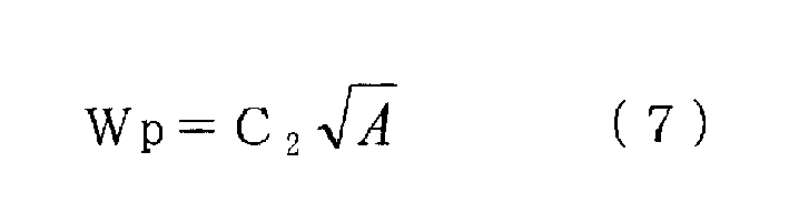
- Furthermore, because the Vickers hardness isobtained by dividing the test force F by the indent area A, the following formula (8) comes into effect when the formula (7) is expressed by using the Vickers hardness HV.

- Then, if the Vickers hardness HV of the formula (8) is replaced with the estimation HVe of the Vickers hardness HV, the formula (6) comes into effect.

-
FIG. 5 is a diagram showing a relation between the work load by plastic deformation Wp and the Vickers hardness HV values obtained by analyzing the indentation curve ofFIGs. 4A-4G . InFIG. 5 , the ordinate axis indicates the work load by plastic deformation Wp, and the abscissa axis indicates the Vickers hardness HV. - Moreover, the straight line of
FIG. 5 expresses the work load by plastic deformation Wp and the Vickers hardness HV with the formula (8) by using the coefficient K. - From
FIG. 5 , it is known that there is a correlation between the work load by plastic deformation Wp and the Vickers hardness HV to all of the samples S including the DLC film. - That is, it is known that the work load by plastic deformation Wp is effective if used at the time of evaluating the correlation with the Vickers hardness HV.
-
FIG. 6 is a flow chart showing a hardness test method by thehardness tester 100. - First, at Step S1, the
CPU 11 judges whether or not a user has instructed to perform the hardness test of the sample S by an operation of theoperation section 9. When theCPU 11 judges that the user does not instruct (Step S1: No), theCPU 11 repeats the processing at Step S1. - On the other hand, if the
CPU 11 judges that the user has instructed (Step S1: Yes), theCPU 11 measures an indentation curve by executing themeasurement program 132 at the succeeding Step S2. - Next, at Step S3, the
CPU 11 calculates the work load by plastic deformation Wp form the indentation curve by executing the workload calculation program 133. - Next, at Step S4, the
CPU 11 calculates the estimation HVe of the Vickers hardness HV by using the work load by plastic deformation Wp and the previously determined coefficient K by executing theestimation calculation program 134, and ends the present processing. - As described above, according to the
hardness tester 100 and the hardness test method of the present embodiment, after measuring an indentation curve, the work load by plastic deformation Wp is calculated from the area of the indentation curve, and the estimation HVe of the Vickers hardness HV is calculated by using the calculated work load Wp and the previously determined coefficient K in conformity with the relational formula: HVe = (K/Wp)2. - Because the work load by plastic deformation Wp is a value having a correlation with the Vickers hardness HV even in the case where the DLC film and the like are used as samples, the estimation HVe of the Vickers hardness HV, which is a value corresponding to the Vickers hardness HV, can be obtained in nanoindentation including the materials expressing remarkable elastic behavior, such as a rubber material and an amorphous material, as objects.
- Moreover, according to the
hardness tester 100 and the hardness test method of the present embodiment, the sample S is made of a diamondlike carbon, a silicon rubber, or a natural rubber. - Consequently, the
hardness tester 100 can measure an evaporated film; a thin film made of a semiconductor material or the like; a surface treated layer; various plastics; various rubbers; brittle materials, such as a microfilament, a glass, and a ceramic; micro electronic parts; and the like. - In addition, the present invention is not limited to the embodiment described above, but can suitably be changed without departing from the spirit and scope of the invention.
- For example, the hardness tester may be configured to move the indenter axis into the axial direction thereof by a drive force generated by supplying a drive current to the drive coil.
Claims (4)
- A hardness test method, comprising the steps of:forming an indent by indenting a surface of a sample with an indenter loaded with a predetermined load and detecting a displacement quantity of the indenter and a test force loaded on the indenter at a time of forming the indent to measure an indentation curve;calculating a work load by plastic deformation (Wp) from an area of an indentation curve obtained by the step of forming the indent; andcalculating an estimation (HVe) of Vickers hardness by using the work load (Wp), calculated at the step of calculating the work load, and a previously determined coefficient K in conformity with
HVe = (K/Wp)2. - The hardness test method according to claim 1, wherein
the sample is made of a material selected from the group consisting of a diamondlike carbon, a silicon rubber, and a natural rubber. - A hardness tester for forming an indent by indenting a surface of a sample with an indenter loaded with a predetermined load, the tester comprising:a measurement section to measure an indentation curve by detecting a displacement quantity of the indenter and a test force loaded on the indenter at a time of forming the indent;a work load calculation section to calculate a work load by plastic deformation (Wp) from an area of an indentation curve obtained by the measurement section; andan estimation calculation section to calculate an estimation (HVe) of Vickers hardness by using the work load (Wp), calculated by the work load calculation section, and a previously determined coefficient K in conformity with HVe = (K/Wp)2.
- A computer-readable storage medium storing a program for enabling a computer to function as:a measurement section to measure an indentation curve by forming an indent by indenting a surface of a sample with an indenter loaded with a predetermined load, and by detecting a displacement quantity of the indenter and a test force loaded on the indenter at a time of forming the indent;a work load calculation section to calculate a work load by plastic deformation (Wp) from an area of an indentation curve obtained by the measurement section; andan estimation calculation section to calculate an estimation (HVe) of Vickers hardness by using the work load (Wp), calculated by the work load calculation section, and a previously determined coefficient K in conformity with
HVe = (K/Wp)2.
Applications Claiming Priority (1)
| Application Number | Priority Date | Filing Date | Title |
|---|---|---|---|
| JP2010006587A JP2011145190A (en) | 2010-01-15 | 2010-01-15 | Hardness test method, hardness tester, and program |
Publications (3)
| Publication Number | Publication Date |
|---|---|
| EP2345884A2 true EP2345884A2 (en) | 2011-07-20 |
| EP2345884A3 EP2345884A3 (en) | 2012-08-22 |
| EP2345884B1 EP2345884B1 (en) | 2018-10-24 |
Family
ID=43838072
Family Applications (1)
| Application Number | Title | Priority Date | Filing Date |
|---|---|---|---|
| EP11150288.6A Active EP2345884B1 (en) | 2010-01-15 | 2011-01-06 | Hardness test method, hardness tester, and computer-readable storage medium storing program |
Country Status (4)
| Country | Link |
|---|---|
| US (1) | US8655602B2 (en) |
| EP (1) | EP2345884B1 (en) |
| JP (1) | JP2011145190A (en) |
| CN (1) | CN102147345B (en) |
Cited By (1)
| Publication number | Priority date | Publication date | Assignee | Title |
|---|---|---|---|---|
| CN103335904A (en) * | 2013-05-31 | 2013-10-02 | 郑州海意科技有限公司 | Measurement device for hardness of filter stick or cigarette |
Families Citing this family (23)
| Publication number | Priority date | Publication date | Assignee | Title |
|---|---|---|---|---|
| JP5777957B2 (en) * | 2011-07-05 | 2015-09-16 | 株式会社ミツトヨ | Hardness tester and hardness test method |
| JP5932341B2 (en) * | 2012-01-06 | 2016-06-08 | 株式会社ミツトヨ | Hardness tester and program |
| CN102589995B (en) * | 2012-02-22 | 2013-09-11 | 西南交通大学 | Method for forecasting uniaxial constitutive relation of material according to press hardness |
| WO2013145111A1 (en) * | 2012-03-26 | 2013-10-03 | 株式会社マツザワ | Hardness testing device and hardness testing method |
| JP6017187B2 (en) * | 2012-05-31 | 2016-10-26 | 株式会社ミツトヨ | Indentation testing machine |
| JP5910407B2 (en) * | 2012-08-09 | 2016-04-27 | 株式会社島津製作所 | Hardness tester and hardness test method in hardness tester |
| CN104122153A (en) * | 2014-07-22 | 2014-10-29 | 中国人民解放军装甲兵工程学院 | Method for determining Vickers hardness of materials based on Vickers instrumented indentation nominal hardness |
| CN111198142B (en) * | 2015-06-25 | 2023-02-10 | 麦克赛尔株式会社 | Hardness Tester |
| JP2017090071A (en) * | 2015-11-04 | 2017-05-25 | 株式会社ミツトヨ | Hardness tester and hardness testing method |
| DE102016100708A1 (en) * | 2016-01-18 | 2017-07-20 | Helmut Fischer GmbH Institut für Elektronik und Messtechnik | Measuring device for detecting measurement signals during a penetration movement of an indenter |
| JP6836408B2 (en) * | 2017-01-27 | 2021-03-03 | 株式会社ミツトヨ | Hardness tester and hardness test method |
| JP2018165643A (en) * | 2017-03-28 | 2018-10-25 | 株式会社ミツトヨ | Hardness testing machine and program |
| CN110702511A (en) * | 2019-10-10 | 2020-01-17 | 南京工程学院 | Heterogeneous welding joint micro-area plastic rheological characterization method |
| JP7462181B2 (en) | 2019-11-29 | 2024-04-05 | 国立研究開発法人理化学研究所 | Three-dimensional microhardness distribution measuring method and three-dimensional microhardness distribution measuring system |
| CN111300061B (en) * | 2020-02-20 | 2022-03-04 | 吉林建筑大学 | A heat pipe production device, production control method and computer program product |
| US12130265B2 (en) * | 2021-03-29 | 2024-10-29 | Colorado State University Research Foundation | Robotic arm nanoindenting for material validation, mass serialization, enhanced joining, and forensic identification |
| CN113899639B (en) * | 2021-08-23 | 2025-05-02 | 惠州市豪鹏科技有限公司 | Battery hardness detection method, device, computer equipment and storage medium |
| US11867295B2 (en) | 2021-09-30 | 2024-01-09 | Tpr Co., Ltd. | Sliding member |
| CN114295504B (en) * | 2021-11-30 | 2023-08-15 | 浙江省计量科学研究院 | A method for measuring ball indentation hardness |
| CN114454325A (en) * | 2022-01-21 | 2022-05-10 | 四川农业大学 | Maintenance system and production method of prefabricated concrete component for assembly type building |
| US12394746B2 (en) * | 2022-05-18 | 2025-08-19 | The Boeing Company | Compression system calibration |
| JP7695974B2 (en) * | 2023-08-10 | 2025-06-19 | 株式会社牧野フライス製作所 | METHOD FOR MEASURING MACHINED AFFECTED LAYER OF WORK, METHOD FOR MACHINING WORK, MACHINED AFFECTED LAYER MEASURING DEVICE, AND MACHINE TOOL |
| CN119147402B (en) * | 2024-11-21 | 2025-05-09 | 邵阳三泰科技有限公司 | A physical property testing device for artificial diamond |
Citations (2)
| Publication number | Priority date | Publication date | Assignee | Title |
|---|---|---|---|---|
| JP2005326169A (en) | 2004-05-12 | 2005-11-24 | Mitsutoyo Corp | Hardness tester and automatic hardness test method |
| JP2009047427A (en) | 2007-08-13 | 2009-03-05 | Mitsutoyo Corp | Test management method and indentation tester in indentation tester |
Family Cites Families (5)
| Publication number | Priority date | Publication date | Assignee | Title |
|---|---|---|---|---|
| AU2002255669A1 (en) * | 2001-03-07 | 2002-09-24 | Massachusetts Institute Of Technology | Systems and methods for estimation and analysis of mechanical property data |
| US7149634B2 (en) * | 2004-01-14 | 2006-12-12 | The Hong Kong Polytechnic University | Method of determining elastic modulus |
| RU2279056C1 (en) * | 2005-04-15 | 2006-06-27 | Государственное образовательное учреждение высшего профессионального образования "Ульяновский государственный технический университет" | Method of determining dynamic microscopic hardness of surface layer on wedge-shaped part |
| JP4320018B2 (en) * | 2006-01-06 | 2009-08-26 | 株式会社レニアス | Micro hardness measurement method and micro hardness tester |
| JP2008197010A (en) * | 2007-02-14 | 2008-08-28 | Fujikura Ltd | Micro hardness tester and hardness measurement method using the same |
-
2010
- 2010-01-15 JP JP2010006587A patent/JP2011145190A/en active Pending
-
2011
- 2011-01-06 EP EP11150288.6A patent/EP2345884B1/en active Active
- 2011-01-11 US US13/004,145 patent/US8655602B2/en active Active
- 2011-01-14 CN CN201110007380.8A patent/CN102147345B/en active Active
Patent Citations (2)
| Publication number | Priority date | Publication date | Assignee | Title |
|---|---|---|---|---|
| JP2005326169A (en) | 2004-05-12 | 2005-11-24 | Mitsutoyo Corp | Hardness tester and automatic hardness test method |
| JP2009047427A (en) | 2007-08-13 | 2009-03-05 | Mitsutoyo Corp | Test management method and indentation tester in indentation tester |
Cited By (2)
| Publication number | Priority date | Publication date | Assignee | Title |
|---|---|---|---|---|
| CN103335904A (en) * | 2013-05-31 | 2013-10-02 | 郑州海意科技有限公司 | Measurement device for hardness of filter stick or cigarette |
| CN103335904B (en) * | 2013-05-31 | 2015-09-02 | 郑州海意科技有限公司 | A kind of filter rod/cigarette hardness measuring device |
Also Published As
| Publication number | Publication date |
|---|---|
| CN102147345B (en) | 2016-07-06 |
| EP2345884A3 (en) | 2012-08-22 |
| US20110178728A1 (en) | 2011-07-21 |
| JP2011145190A (en) | 2011-07-28 |
| EP2345884B1 (en) | 2018-10-24 |
| CN102147345A (en) | 2011-08-10 |
| US8655602B2 (en) | 2014-02-18 |
Similar Documents
| Publication | Publication Date | Title |
|---|---|---|
| EP2345884B1 (en) | Hardness test method, hardness tester, and computer-readable storage medium storing program | |
| Hay et al. | Instrumented indentation testing | |
| Motra et al. | Assessment of strain measurement techniques to characterise mechanical properties of structural steel | |
| US8087282B2 (en) | Test management method for indentation tester and indentation tester | |
| US8074497B2 (en) | Indentation testing instrument and indentation testing method | |
| JP5932341B2 (en) | Hardness tester and program | |
| Photiou et al. | On the conical indentation response of elastic auxetic materials: effects of Poisson's ratio, contact friction and cone angle | |
| Lu et al. | Estimation of surface equi-biaxial residual stress by using instrumented sharp indentation | |
| US20170122856A1 (en) | Hardness testing apparatus and hardness testing method | |
| JP5501192B2 (en) | Hardness test method and program | |
| JP6615561B2 (en) | Hardness testing machine | |
| Charleux et al. | A method for measuring the contact area in instrumented indentation testing by tip scanning probe microscopy imaging | |
| JP2018119900A (en) | Hardness tester and hardness testing method | |
| JP5760244B2 (en) | Low cycle fatigue crack growth evaluation method | |
| Peng et al. | Characterization of the viscoelastic-plastic properties of UPVC by instrumented sharp indentation | |
| Choi et al. | Evaluation of nonequibiaxial residual stress using Knoop indenter | |
| Kim et al. | Determination of dynamic strain hardening parameters using the virtual fields method | |
| Satošek et al. | Study of influential parameters of the sphere indentation used for the control function of material properties in forming operations | |
| Shim et al. | A critical examination of the Berkovich vs. conical indentation based on 3D finite element calculation | |
| JP2013019862A (en) | Indenter, hardness testing device, and hardness testing method | |
| KR102521067B1 (en) | Evaluation system of directionality of material yield strength using spherical indentation and surface displacement analysis | |
| Cagliero et al. | Influence of Vickers Indenter Tip Geometry on the Macro-indentation Properties of γ-TiAl Alloys | |
| Ramirez | Microparticle compression strength with micro indentation | |
| RU2475722C2 (en) | Bulk material identification method and device for its implementation | |
| Sivaram et al. | Development of Indentation Testing Method for Evaluation of Mechanical Properties of Steel Reinforcement |
Legal Events
| Date | Code | Title | Description |
|---|---|---|---|
| PUAI | Public reference made under article 153(3) epc to a published international application that has entered the european phase |
Free format text: ORIGINAL CODE: 0009012 |
|
| AK | Designated contracting states |
Kind code of ref document: A2 Designated state(s): AL AT BE BG CH CY CZ DE DK EE ES FI FR GB GR HR HU IE IS IT LI LT LU LV MC MK MT NL NO PL PT RO RS SE SI SK SM TR |
|
| AX | Request for extension of the european patent |
Extension state: BA ME |
|
| PUAL | Search report despatched |
Free format text: ORIGINAL CODE: 0009013 |
|
| AK | Designated contracting states |
Kind code of ref document: A3 Designated state(s): AL AT BE BG CH CY CZ DE DK EE ES FI FR GB GR HR HU IE IS IT LI LT LU LV MC MK MT NL NO PL PT RO RS SE SI SK SM TR |
|
| AX | Request for extension of the european patent |
Extension state: BA ME |
|
| RIC1 | Information provided on ipc code assigned before grant |
Ipc: G01N 3/02 20060101ALN20120719BHEP Ipc: G01N 3/42 20060101AFI20120719BHEP Ipc: G01N 3/00 20060101ALN20120719BHEP |
|
| 17P | Request for examination filed |
Effective date: 20130219 |
|
| GRAP | Despatch of communication of intention to grant a patent |
Free format text: ORIGINAL CODE: EPIDOSNIGR1 |
|
| STAA | Information on the status of an ep patent application or granted ep patent |
Free format text: STATUS: GRANT OF PATENT IS INTENDED |
|
| RIC1 | Information provided on ipc code assigned before grant |
Ipc: G01N 3/42 20060101AFI20180425BHEP Ipc: G01N 3/00 20060101ALN20180425BHEP Ipc: G01N 3/02 20060101ALN20180425BHEP |
|
| INTG | Intention to grant announced |
Effective date: 20180518 |
|
| GRAS | Grant fee paid |
Free format text: ORIGINAL CODE: EPIDOSNIGR3 |
|
| GRAA | (expected) grant |
Free format text: ORIGINAL CODE: 0009210 |
|
| STAA | Information on the status of an ep patent application or granted ep patent |
Free format text: STATUS: THE PATENT HAS BEEN GRANTED |
|
| AK | Designated contracting states |
Kind code of ref document: B1 Designated state(s): AL AT BE BG CH CY CZ DE DK EE ES FI FR GB GR HR HU IE IS IT LI LT LU LV MC MK MT NL NO PL PT RO RS SE SI SK SM TR |
|
| REG | Reference to a national code |
Ref country code: GB Ref legal event code: FG4D |
|
| REG | Reference to a national code |
Ref country code: CH Ref legal event code: EP |
|
| REG | Reference to a national code |
Ref country code: IE Ref legal event code: FG4D |
|
| REG | Reference to a national code |
Ref country code: DE Ref legal event code: R096 Ref document number: 602011053125 Country of ref document: DE Ref country code: AT Ref legal event code: REF Ref document number: 1057271 Country of ref document: AT Kind code of ref document: T Effective date: 20181115 |
|
| REG | Reference to a national code |
Ref country code: NL Ref legal event code: MP Effective date: 20181024 |
|
| REG | Reference to a national code |
Ref country code: LT Ref legal event code: MG4D |
|
| REG | Reference to a national code |
Ref country code: AT Ref legal event code: MK05 Ref document number: 1057271 Country of ref document: AT Kind code of ref document: T Effective date: 20181024 |
|
| PG25 | Lapsed in a contracting state [announced via postgrant information from national office to epo] |
Ref country code: NL Free format text: LAPSE BECAUSE OF FAILURE TO SUBMIT A TRANSLATION OF THE DESCRIPTION OR TO PAY THE FEE WITHIN THE PRESCRIBED TIME-LIMIT Effective date: 20181024 |
|
| PG25 | Lapsed in a contracting state [announced via postgrant information from national office to epo] |
Ref country code: ES Free format text: LAPSE BECAUSE OF FAILURE TO SUBMIT A TRANSLATION OF THE DESCRIPTION OR TO PAY THE FEE WITHIN THE PRESCRIBED TIME-LIMIT Effective date: 20181024 Ref country code: AT Free format text: LAPSE BECAUSE OF FAILURE TO SUBMIT A TRANSLATION OF THE DESCRIPTION OR TO PAY THE FEE WITHIN THE PRESCRIBED TIME-LIMIT Effective date: 20181024 Ref country code: LV Free format text: LAPSE BECAUSE OF FAILURE TO SUBMIT A TRANSLATION OF THE DESCRIPTION OR TO PAY THE FEE WITHIN THE PRESCRIBED TIME-LIMIT Effective date: 20181024 Ref country code: FI Free format text: LAPSE BECAUSE OF FAILURE TO SUBMIT A TRANSLATION OF THE DESCRIPTION OR TO PAY THE FEE WITHIN THE PRESCRIBED TIME-LIMIT Effective date: 20181024 Ref country code: BG Free format text: LAPSE BECAUSE OF FAILURE TO SUBMIT A TRANSLATION OF THE DESCRIPTION OR TO PAY THE FEE WITHIN THE PRESCRIBED TIME-LIMIT Effective date: 20190124 Ref country code: IS Free format text: LAPSE BECAUSE OF FAILURE TO SUBMIT A TRANSLATION OF THE DESCRIPTION OR TO PAY THE FEE WITHIN THE PRESCRIBED TIME-LIMIT Effective date: 20190224 Ref country code: NO Free format text: LAPSE BECAUSE OF FAILURE TO SUBMIT A TRANSLATION OF THE DESCRIPTION OR TO PAY THE FEE WITHIN THE PRESCRIBED TIME-LIMIT Effective date: 20190124 Ref country code: PL Free format text: LAPSE BECAUSE OF FAILURE TO SUBMIT A TRANSLATION OF THE DESCRIPTION OR TO PAY THE FEE WITHIN THE PRESCRIBED TIME-LIMIT Effective date: 20181024 Ref country code: HR Free format text: LAPSE BECAUSE OF FAILURE TO SUBMIT A TRANSLATION OF THE DESCRIPTION OR TO PAY THE FEE WITHIN THE PRESCRIBED TIME-LIMIT Effective date: 20181024 Ref country code: LT Free format text: LAPSE BECAUSE OF FAILURE TO SUBMIT A TRANSLATION OF THE DESCRIPTION OR TO PAY THE FEE WITHIN THE PRESCRIBED TIME-LIMIT Effective date: 20181024 |
|
| PG25 | Lapsed in a contracting state [announced via postgrant information from national office to epo] |
Ref country code: SE Free format text: LAPSE BECAUSE OF FAILURE TO SUBMIT A TRANSLATION OF THE DESCRIPTION OR TO PAY THE FEE WITHIN THE PRESCRIBED TIME-LIMIT Effective date: 20181024 Ref country code: RS Free format text: LAPSE BECAUSE OF FAILURE TO SUBMIT A TRANSLATION OF THE DESCRIPTION OR TO PAY THE FEE WITHIN THE PRESCRIBED TIME-LIMIT Effective date: 20181024 Ref country code: GR Free format text: LAPSE BECAUSE OF FAILURE TO SUBMIT A TRANSLATION OF THE DESCRIPTION OR TO PAY THE FEE WITHIN THE PRESCRIBED TIME-LIMIT Effective date: 20190125 Ref country code: PT Free format text: LAPSE BECAUSE OF FAILURE TO SUBMIT A TRANSLATION OF THE DESCRIPTION OR TO PAY THE FEE WITHIN THE PRESCRIBED TIME-LIMIT Effective date: 20190224 Ref country code: AL Free format text: LAPSE BECAUSE OF FAILURE TO SUBMIT A TRANSLATION OF THE DESCRIPTION OR TO PAY THE FEE WITHIN THE PRESCRIBED TIME-LIMIT Effective date: 20181024 |
|
| REG | Reference to a national code |
Ref country code: DE Ref legal event code: R097 Ref document number: 602011053125 Country of ref document: DE |
|
| PG25 | Lapsed in a contracting state [announced via postgrant information from national office to epo] |
Ref country code: CZ Free format text: LAPSE BECAUSE OF FAILURE TO SUBMIT A TRANSLATION OF THE DESCRIPTION OR TO PAY THE FEE WITHIN THE PRESCRIBED TIME-LIMIT Effective date: 20181024 Ref country code: IT Free format text: LAPSE BECAUSE OF FAILURE TO SUBMIT A TRANSLATION OF THE DESCRIPTION OR TO PAY THE FEE WITHIN THE PRESCRIBED TIME-LIMIT Effective date: 20181024 Ref country code: DK Free format text: LAPSE BECAUSE OF FAILURE TO SUBMIT A TRANSLATION OF THE DESCRIPTION OR TO PAY THE FEE WITHIN THE PRESCRIBED TIME-LIMIT Effective date: 20181024 |
|
| PG25 | Lapsed in a contracting state [announced via postgrant information from national office to epo] |
Ref country code: SK Free format text: LAPSE BECAUSE OF FAILURE TO SUBMIT A TRANSLATION OF THE DESCRIPTION OR TO PAY THE FEE WITHIN THE PRESCRIBED TIME-LIMIT Effective date: 20181024 Ref country code: RO Free format text: LAPSE BECAUSE OF FAILURE TO SUBMIT A TRANSLATION OF THE DESCRIPTION OR TO PAY THE FEE WITHIN THE PRESCRIBED TIME-LIMIT Effective date: 20181024 Ref country code: EE Free format text: LAPSE BECAUSE OF FAILURE TO SUBMIT A TRANSLATION OF THE DESCRIPTION OR TO PAY THE FEE WITHIN THE PRESCRIBED TIME-LIMIT Effective date: 20181024 Ref country code: SM Free format text: LAPSE BECAUSE OF FAILURE TO SUBMIT A TRANSLATION OF THE DESCRIPTION OR TO PAY THE FEE WITHIN THE PRESCRIBED TIME-LIMIT Effective date: 20181024 Ref country code: MC Free format text: LAPSE BECAUSE OF FAILURE TO SUBMIT A TRANSLATION OF THE DESCRIPTION OR TO PAY THE FEE WITHIN THE PRESCRIBED TIME-LIMIT Effective date: 20181024 |
|
| PLBE | No opposition filed within time limit |
Free format text: ORIGINAL CODE: 0009261 |
|
| REG | Reference to a national code |
Ref country code: CH Ref legal event code: PL |
|
| STAA | Information on the status of an ep patent application or granted ep patent |
Free format text: STATUS: NO OPPOSITION FILED WITHIN TIME LIMIT |
|
| PG25 | Lapsed in a contracting state [announced via postgrant information from national office to epo] |
Ref country code: LU Free format text: LAPSE BECAUSE OF NON-PAYMENT OF DUE FEES Effective date: 20190106 |
|
| 26N | No opposition filed |
Effective date: 20190725 |
|
| REG | Reference to a national code |
Ref country code: BE Ref legal event code: MM Effective date: 20190131 |
|
| REG | Reference to a national code |
Ref country code: IE Ref legal event code: MM4A |
|
| PG25 | Lapsed in a contracting state [announced via postgrant information from national office to epo] |
Ref country code: FR Free format text: LAPSE BECAUSE OF NON-PAYMENT OF DUE FEES Effective date: 20190131 Ref country code: SI Free format text: LAPSE BECAUSE OF FAILURE TO SUBMIT A TRANSLATION OF THE DESCRIPTION OR TO PAY THE FEE WITHIN THE PRESCRIBED TIME-LIMIT Effective date: 20181024 |
|
| PG25 | Lapsed in a contracting state [announced via postgrant information from national office to epo] |
Ref country code: BE Free format text: LAPSE BECAUSE OF NON-PAYMENT OF DUE FEES Effective date: 20190131 |
|
| PG25 | Lapsed in a contracting state [announced via postgrant information from national office to epo] |
Ref country code: LI Free format text: LAPSE BECAUSE OF NON-PAYMENT OF DUE FEES Effective date: 20190131 Ref country code: CH Free format text: LAPSE BECAUSE OF NON-PAYMENT OF DUE FEES Effective date: 20190131 |
|
| PG25 | Lapsed in a contracting state [announced via postgrant information from national office to epo] |
Ref country code: IE Free format text: LAPSE BECAUSE OF NON-PAYMENT OF DUE FEES Effective date: 20190106 |
|
| PG25 | Lapsed in a contracting state [announced via postgrant information from national office to epo] |
Ref country code: TR Free format text: LAPSE BECAUSE OF FAILURE TO SUBMIT A TRANSLATION OF THE DESCRIPTION OR TO PAY THE FEE WITHIN THE PRESCRIBED TIME-LIMIT Effective date: 20181024 |
|
| PG25 | Lapsed in a contracting state [announced via postgrant information from national office to epo] |
Ref country code: MT Free format text: LAPSE BECAUSE OF NON-PAYMENT OF DUE FEES Effective date: 20190106 |
|
| PG25 | Lapsed in a contracting state [announced via postgrant information from national office to epo] |
Ref country code: CY Free format text: LAPSE BECAUSE OF FAILURE TO SUBMIT A TRANSLATION OF THE DESCRIPTION OR TO PAY THE FEE WITHIN THE PRESCRIBED TIME-LIMIT Effective date: 20181024 |
|
| PG25 | Lapsed in a contracting state [announced via postgrant information from national office to epo] |
Ref country code: HU Free format text: LAPSE BECAUSE OF FAILURE TO SUBMIT A TRANSLATION OF THE DESCRIPTION OR TO PAY THE FEE WITHIN THE PRESCRIBED TIME-LIMIT; INVALID AB INITIO Effective date: 20110106 |
|
| PG25 | Lapsed in a contracting state [announced via postgrant information from national office to epo] |
Ref country code: MK Free format text: LAPSE BECAUSE OF FAILURE TO SUBMIT A TRANSLATION OF THE DESCRIPTION OR TO PAY THE FEE WITHIN THE PRESCRIBED TIME-LIMIT Effective date: 20181024 |
|
| PGFP | Annual fee paid to national office [announced via postgrant information from national office to epo] |
Ref country code: GB Payment date: 20260123 Year of fee payment: 16 |
|
| PGFP | Annual fee paid to national office [announced via postgrant information from national office to epo] |
Ref country code: DE Payment date: 20260121 Year of fee payment: 16 |