EP2345869A1 - Lever-type detector, stylus, and automatic stylus exchanger - Google Patents
Lever-type detector, stylus, and automatic stylus exchanger Download PDFInfo
- Publication number
- EP2345869A1 EP2345869A1 EP10197161A EP10197161A EP2345869A1 EP 2345869 A1 EP2345869 A1 EP 2345869A1 EP 10197161 A EP10197161 A EP 10197161A EP 10197161 A EP10197161 A EP 10197161A EP 2345869 A1 EP2345869 A1 EP 2345869A1
- Authority
- EP
- European Patent Office
- Prior art keywords
- stylus
- seating
- shaft body
- lever
- gravity
- Prior art date
- Legal status (The legal status is an assumption and is not a legal conclusion. Google has not performed a legal analysis and makes no representation as to the accuracy of the status listed.)
- Granted
Links
Images










Classifications
-
- G—PHYSICS
- G01—MEASURING; TESTING
- G01B—MEASURING LENGTH, THICKNESS OR SIMILAR LINEAR DIMENSIONS; MEASURING ANGLES; MEASURING AREAS; MEASURING IRREGULARITIES OF SURFACES OR CONTOURS
- G01B5/00—Measuring arrangements characterised by the use of mechanical techniques
- G01B5/004—Measuring arrangements characterised by the use of mechanical techniques for measuring coordinates of points
- G01B5/008—Measuring arrangements characterised by the use of mechanical techniques for measuring coordinates of points using coordinate measuring machines
- G01B5/012—Contact-making feeler heads therefor
-
- G—PHYSICS
- G01—MEASURING; TESTING
- G01B—MEASURING LENGTH, THICKNESS OR SIMILAR LINEAR DIMENSIONS; MEASURING ANGLES; MEASURING AREAS; MEASURING IRREGULARITIES OF SURFACES OR CONTOURS
- G01B5/00—Measuring arrangements characterised by the use of mechanical techniques
- G01B5/28—Measuring arrangements characterised by the use of mechanical techniques for measuring roughness or irregularity of surfaces
Definitions
- the present invention relates to lever-type detectors, styluses, and automatic stylus exchangers used in surface-property measuring machines, and more specifically, to improvements to a lever-type detector having a detachable stylus and an automatic stylus exchanger for attaching and detaching the stylus to and from the detector automatically.
- a known surface roughness tester brings its stylus into contact with the surface of a workpiece, moves the stylus along a surface of the workpiece, detects the displacement of the stylus caused by the surface roughness, and determines the surface roughness from the displacement (refer to Japanese Patent Application Publication No. 2000-74616 , for example).
- the lever-type detector mounted to the surface roughness tester illustrated in Figs. 3 and 9 in Japanese Patent Application Publication No. 2000-74616 has a stylus that is brought into contact with the workpiece and a stylus holder that holds the stylus detachably.
- the operator of the surface roughness tester exchanges the stylus to one suitable for a workpiece measurement portion before starting measurement. For example, before starting measurement, the operator sets up a bore testing stylus to measure the surface roughness of a bore or sets up a deep-groove testing stylus having a long length to measure the surface roughness of a deep groove.
- surface-property measuring machines such as a roundness measuring machine and a contour-shape measuring machine also have styluses in different shapes prepared for various workpiece measurement portions to deal with diversified kinds of measurement.
- the operator exchanges the stylus. To do so, the operator temporarily stops the measurement, removes the current stylus from the detector, attaches a new stylus to the detector, and resumes the measurement.
- the automatic probe changer used with three-dimensional measuring machines and the like could be applied to a surface-property measuring machine.
- the measuring machine may be equipped with an exchange rack storing different types of styluses, so that the stylus on the detector can be exchanged automatically.
- an object of the present invention is to provide a lever-type detector, a stylus, and an automatic stylus exchanger that allow styluses of different types to be exchanged automatically and reduce the burden of exchanging the styluses of different types for the lever-type detector.
- a lever-type detector including a stylus having a contact part that comes into contact with a workpiece; a stylus holder that supports the stylus swingably; and displacement detection means for detecting a swinging displacement of the stylus; and the lever-type detector obtains the swinging displacement of the stylus in order to measure a surface property of the workpiece.
- the stylus includes a long stylus body having the contact part at a tip end and a seating that is disposed in a base end of the stylus body and is detachable from the stylus holder.
- the stylus holder includes a shaft body that serves as the center of swinging of the stylus.
- the seating contains the position of the center of gravity of the whole stylus separated from the stylus holder and has a notch for guiding the shaft body to the center of gravity of the stylus when the stylus is attached.
- the seating In a state in which the shaft body is guided to the center of gravity through the notch, the seating is detachably held by the stylus holder, and the stylus becomes swingable about the shaft body.
- the shape of the notch may be an approximately U shape, an approximately V shape, or an approximately L shape, and is not limited.
- the shaft body provided for the stylus holder may be supported by the stylus holder rotatably or may be fixed to the stylus holder. In the latter case, a swinging member, described later, rotates about the central axis of the shaft body fixed.
- the seating of the stylus include a counterbalance for adjusting the position of the center of gravity such that the center of gravity of the whole stylus is placed in the notch of the seating.
- the lever-type detector further include styluses of different types prepared for measurement of different portions of the workpiece, each of the styluses have a locking part that can lock a part provided for an exchange rack that accommodates the styluses and allows the styluses to be taken out; and the locking part be disposed in the seating of each of the styluses in a position offset with respect to the counterbalance in the direction of a swinging axis of the shaft body.
- the locking part disposed in the seating locks the part provided for the exchange rack.
- the held stylus is detached from the stylus holder.
- These two operations are executed in close coordination. More specifically, to detach the stylus from the stylus holder, the stylus holder is moved toward the exchange rack to make the locking part engage with the part provided for the exchange rack. Then, while this engagement is maintained, when the detector is moved away from the exchange rack, the seating is detached from the stylus holder, allowing the stylus to be stored in the exchange rack. Conversely, to mount a stylus to the stylus holder, the stylus holder is moved toward the exchange rack to guide the shaft body of the stylus holder to the center of gravity of the stylus, mounting the seating of the stylus to the stylus holder. Then, the stylus holder is moved in a direction in which the locking condition of the locking part is released to take out the stylus from the exchange rack.
- the stylus holder include a swinging member supported by the shaft body; in a state in which the shaft body is guided to the center of gravity of the stylus, the swinging member and the seating be placed side by side along the direction of a swinging axis of the shaft body; and the swinging member include an elastic holding member for holding the seating by pressing it against the swinging member with an elastic force and a support for supporting the elastic holding member.
- the elastic holding member be rotatably supported by the support at a base end, and when the stylus is attached to the stylus holder, the elastic holding member be pressed at a tip end by the seating, generate elastic deformation while rotating, and use the resultant elastic force to hold the seating by pressing it against the swinging member.
- the elastic holding member be cantilevered by the support at a base end, and when the stylus is attached to the stylus holder, the elastic holding member be pressed at a tip end to become far from the swinging member by the seating, generates elastic deformation based on a bend, and use the resultant elastic force to hold the seating by pressing it against the swinging member.
- the seating In a state in which the stylus is attached to the stylus holder, it is preferred that the seating have the notch located between two protrusions provided for the seating protruding forward the elastic holding member.
- the elastic holding member be flat and cantilevered by the support at a base end, and pressed at a tip end to become far from the swinging member by the protrusions.
- the support be extended in the direction of the swinging axis of the shaft body from the swinging member through the notch and support the elastic holding member at a extended tip end.
- At least three balls be placed between the seating and the swinging member in at least three positions that are not in a straight line, and the balls be used to position the seating with respect to the swinging member in the direction of the swinging axis of the shaft body. And it is preferred that at least two of the balls be rotatably supported by the seating, and when the stylus is attached to the stylus holder, the balls roll on a groove formed in the swinging member along the direction in which the shaft body is guided to the center of gravity.
- an automatic stylus exchanger including the above-described lever-type detector; an exchange rack that accommodates styluses of different types prepared for different portions to be measured in a workpiece and allows the styluses to be taken out; a detector drive mechanism for moving the lever-type detector in a direction for approaching or separating from the exchange rack; and a controller.
- the controller controls the detector drive mechanism and performs a stylus exchange operation between the stylus holder and the exchange rack.
- the exchange rack comprise a locked part and a part for preventing.
- the locked part is projecting in a moving direction of the lever-type detector in order to guide the stylus locked by a locking part disposed in the seating into a accommodating position when the lever-type detector moves in a direction orthogonal to the direction in which the shaft body is guided to the center of gravity of the stylus on a flat face provided for the seating.
- the part for preventing the stylus from moving in the direction in which the shaft body is guided to the center of gravity of the stylus is accommodated by the exchange rack when the lever-type detector moves in a direction in which the shaft body is guided to the center of gravity of the stylus.
- the exchange rack comprise a locked part and a part for preventing.
- the locked part is projecting in a moving direction of the lever-type detector in order to guide the stylus locked by a locking part disposed in the seating into a accommodating position when the lever-type detector moves in a direction in which the shaft body is guided to the center of gravity of the stylus on a flat face provided for the seating. And in a state in which the stylus is in the accommodating position, the part for preventing the stylus from moving in the direction in which the shaft body is guided to the center of gravity of the stylus.
- the part for preventing is provided so as to move forward and backward between a position for locking the seating in order to prevent the stylus from moving and a position for releasing a lock of the seating.
- a lever-type detector has a seating integrally formed with a stylus body at a base end of a stylus, opposite to a contact part of the stylus.
- the seating of the stylus is held by a stylus holder detachably.
- the stylus body and the seating may be produced separately and then integrated.
- the seating of the stylus has a notch used to guide a shaft body, which serves as a swinging axis of the stylus, to the center of gravity of the stylus. Attachment through the notch allows the shaft body to reach the center of gravity of the stylus. Since the center of gravity of any stylus is placed on the same axis as the shaft body, which is the center of swinging of the lever-type detector, even after the stylus is changed to a different type, the whole stylus, including the swinging member, is kept in good balance, and measurement can be continued with the same measuring force as that used before the exchange. This eliminates the need for stylus balance adjustment after the exchange, especially in precise measurement, and consequently, the detector does not need to include a balance adjustment mechanism.
- the seating has a counterbalance for adjusting the position of the center of gravity to bring the center of gravity of the whole stylus into the notch of the seating.
- the center of gravity of the second stylus can be set in the same position as set by the seating for the first stylus because of the counterbalance disposed on the seating of the second stylus.
- the counterbalance allows standardization of the basic shape of the seating among styluses of different types.
- the counterbalance can be scaled up or down more freely, and consequently a stylus of a special shape can be produced more easily.
- the present invention employs a mechanism for holding the stylus with an elastic force. Since the swinging member is provided with an elastic holding member for holding the seating by pressing it against the swinging member with an elastic force, the stylus holding mechanism can have a simplified configuration and lower weight in comparison with a magnetic holding mechanism.
- the elastic holding member has its base end rotatably supported by a support.
- the stylus When the stylus is attached to the stylus holder, it is pressed by the seating at its tip end, exhibits elastic deformation as it rotates, and holds the seating by pressing it against the swinging member with the elastic force. Therefore, the seating can be held by the swinging member just by inserting it, and the seating can be detached from the swinging member just by pulling it.
- the stylus holding mechanism configured as a so-called toggle joint facilitates the exchange process.
- the elastic holding member does not produce an elastic force before its tip is pressed by the seating.
- the elastic holding member rotates, exhibiting elastic deformation, and the elastic force exerted on the seating increases gradually.
- the elastic holding member is rotated to a predetermined position, the seating is held by the swinging member with a predetermined holding force.
- the seating of the stylus comes into contact with the tip of the elastic holding member, moves a short distance further, and is then completely held by the swinging member.
- the stylus holding mechanism is configured with a simple flat spring mechanism for attachment-detachment of the stylus instead of the toggle joint. Consequently, the stylus holding mechanism can have a still lower weight, improve steadiness of automatic stylus exchanging and usefulness.
- a plurality of balls are provided in at least three positions that are not in a straight line between the seating and the swinging member. With the balls, the seating is positioned with respect to the swinging member, so that the seating is accurately positioned in the direction of the central axis of the shaft body.
- the shaft body is guided accurately to the center of gravity of the stylus. Accordingly, the positional relationship between the swinging member and the seating can be reproduced accurately, and unevenness in measured values caused by exchanging the stylus are reduced.
- An automatic stylus exchanger eliminates the need for stylus balance adjustment in automatic exchange, allows measurement to be continued with the same measuring force even after the stylus is exchanged with one of a different type, and has other advantages, as described earlier.
- a lever-type detector and a stylus according to the present invention can reduce the burden of manual exchange of a plurality of styluses, and an automatic stylus exchanger according to the present invention can automatically exchange styluses of different types in a lever-type detector.
- Fig. 1 is a perspective view of a roundness measuring machine according to a first embodiment of the present invention.
- Fig. 2A is a perspective view of a detector in the roundness measuring machine
- Fig. 2B is a perspective view showing the internal structure of the detector.
- Fig. 3A is a perspective view of a swinging member of the detector
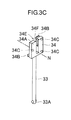
- Figs. 3B and 3C are perspective views of a stylus from different angles.
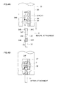
- Fig. 4A is a partial sectional view of the detector before the stylus is attached to a stylus holder
- Fig. 4B is a partial sectional view after the stylus is attached.
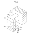
- Fig. 5 is a perspective view showing a flat spring of the stylus holder supported by the swinging member.
- Figs. 6A to 6C are enlarged partial sectional views of an area I in Fig. 4B .
- Fig. 6A shows an initial state when the flat spring starts rotating;
- Fig. 6B shows the flat spring rotated by a predetermined angle; and
- Fig. 6C shows the flat spring rotated until a predetermined holding power is generated.
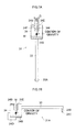
- Figs. 7A and 7B illustrate the positions of the centers of gravity in different types of styluses.
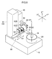
- Fig. 8 is a perspective view of the roundness measuring machine shown in Fig. 1 with an exchange rack, seen from a different angle.
- Figs. 9A and 9B are views illustrating a procedure for exchanging the stylus in the machine shown in Fig. 8 .
- Fig. 9A is a perspective view showing a state before the stylus is taken out of the exchange rack.
- Fig. 9B is a perspective view showing a state after the stylus is taken out.
- Figs. 10 A and 10B are partial side views of a stylus holder of a detector according to a second embodiment.
- Fig. 10A shows a state before a stylus is attached
- Fig. 10B shows a state after the attachment.
- Figs. 11A and 11 B show seatings for different types of styluses according to modifications of the present invention.
- Fig. 12 is a perspective view of a stylus attachment-detachment mechanism of a lever type detector according to a second embodiment of the present invention.
- Fig. 13A is a partial side view of the swinging member before the stylus is attached to a stylus holder
- Fig. 13B is a partial side view of the positional relationship between the swinging member and the seating after the stylus is attached.
- Fig. 14 is enlarged partial side view of an area II in Fig. 13 .
- Fig. 15 is a perspective view of the positional relationship between a stocker and a detector before the stylus is taken out of the stocker.
- Figs. 16A to 16C are views illustrating a procedure for exchanging the stylus.
- Fig. 16A is a perspective view showing a state before the stylus is taken out of the stocker.
- Fig. 16B is a perspective view showing a state in which the stylus is attached to the swinging member.
- Fig. 16C is a perspective view showing a state after the stylus is taken out of the stocker.
- Figs. 17A and 17B are views illustrating a operation of an upper support of the stocker.
- Fig. 17A is a perspective view showing a releasing position.
- Fig. 17B is a perspective view showing a locking position.
- Figs. 18 is a back view showing a driver of the upper support of the stocker.
- Fig. 1 is a perspective view of a roundness measuring machine according to a first embodiment of the present invention.
- the roundness measuring machine of the first embodiment includes a base 10, a turntable 20 provided on one side of the base 10 to turn about the vertical central axis L and to support a workpiece W on its top surface, a lever-type detector 30, a detector drive mechanism 40 that moves the lever-type detector 30 toward or away from the turntable 20 in the direction of the vertical central axis L and a direction orthogonal to the vertical central axis L, and a controller 50.
- the turntable 20 contains a turntable drive mechanism 21, which is not shown in the figure.
- the turntable drive mechanism 21 can turn the turntable 20 around the vertical central axis L.
- the turntable drive mechanism 21 includes a motor for turning the turntable 20 or a mechanism for transferring the rotation of a motor through a decelerator to the turntable 20.
- the lever-type detector 30 includes a stylus 31 to be brought into contact with the workpiece W and a stylus holder 32 that holds the stylus 31 detachably and detects the displacement of the stylus 31 as an electrical signal.
- the stylus 31 is supported to swing about a swinging axis provided in the stylus holder 32. Therefore, the detected displacement of the stylus 31 is the amount of rotational displacement of the stylus 31. However, since the amount of displacement is tiny with respect to the turning radius of the stylus 31, the detected displacement becomes the amount of displacement in a direction orthogonal to the longitudinal direction of the stylus 31.
- the detector drive mechanism 40 includes a column 41 provided upright on the other side of the base 10, a vertical motion drive mechanism 43 that moves a vertical slider 42 in the vertical direction (Z direction) along the column 41, a first horizontal motion drive mechanism 45 that slides a slide arm 44 toward or away from the turntable 20 in the direction (X direction) orthogonal to the vertical central axis L, with respect to the vertical slider 42, a detector arm 46 that is provided at an end of the slide arm 44 to hold the detector 30, and a rotational motion drive mechanism 47 (not shown in the figure) that turns the detector arm 46 around the sliding axis of the slide arm 44 to change the orientation of the detector 30.
- the vertical motion drive mechanism 43 can have any structure so long as it can move the vertical slider 42 up and down.
- the vertical motion drive mechanism 43 can be a feed mechanism that includes a ball thread shaft standing upright in the vertical direction in the column 41, a motor for turning the ball thread shaft, and a nut coupled with the vertical slider 42 engaged with the ball thread shaft.
- the first horizontal motion drive mechanism 45 can have any structure so long as it can move the slide arm 44 toward or away from the turntable 20 in the direction orthogonal to the vertical central axis L.
- the first horizontal motion drive mechanism 45 can be a mechanism in the vertical slider 42, which includes a rack formed along the longitudinal direction of the slide arm 44 and a pinion that engages with the rack, a motor for turning the pinion, and the like.
- the detector drive mechanism 40 When a measurement program stored in a program storage section 51 of the controller 50 gives a measurement command to the controller 50, the detector drive mechanism 40 is driven. The vertical motion drive mechanism 43 and the first horizontal motion drive mechanism 45 move the detector 30 toward the workpiece W, and the stylus 31 of the detector 30 is brought into contact with the workpiece W. When necessary, the rotational motion drive mechanism 47 is operated to change the orientation of the detector 30. If the turntable 20 turns in this state, the stylus 31 of the detector 30 is displaced in accordance with the roundness of the workpiece W. The displacement of the stylus 31 is detected by the stylus holder 32 as an electrical signal and is then taken into the controller 50. The controller 50 stores the measurement data in a data storage section 52, calculates the roundness from the data, displays the result on a display unit 53, and prints out the result, if necessary.
- FIG. 2A shows a perspective view of the detector 30, and Fig. 2B shows the internal structure.
- the stylus 31 is supported to swing about a swing bearing 32A disposed in the stylus holder 32.
- the detector 30 also has a mechanism for attaching and detaching the stylus 31.
- the detector 30 has a flat swinging member 37 that is supported to turn around a shaft body 36, which serves as a swinging axis.
- the flat swinging member 37 is configured to hold the stylus 31 detachably.
- Figs. 3B and 3C show perspective views of the stylus 31 from different angles.
- the stylus 31 includes a long stylus body 33 having a contact part 33A at its tip end and a seating plate 34 integrally formed with the base end of the stylus body 33.
- the stylus body 33 has a long cylindrical shape and two cemented carbide balls, which are contact parts 33A, fixed in one end of the cylinder.
- the two cemented carbide balls are half buried in the side face of the cylinder end at intervals of 180 degrees.
- the illustrated stylus 31 is just one example of various styluses.
- the stylus bodies 33 of the various styluses 31 have different longitudinal lengths and different cylindrical diameters.
- Some styluses have just a single cemented carbide ball buried at the cylinder end as the contact part 33A.
- the shape of the contact parts 33A is not limited to a sphere and can be a circular cone having a spherical tip.
- the material of the contact parts 33A can be sapphire or the like.
- the seating plate 34 is an approximately rectangular plate, and its central axis and the central axis of the stylus body 33 lie on a single straight line.
- the seating plate 34 which corresponds to a seating in the present invention, includes a body 34A, two locking parts 34B having different lengths, and three steel positioning balls 34C (see Fig. 3C ).
- the shape of the seating plate 34 is determined so as to place the center of gravity of the whole stylus 31, which includes both the seating plate 34 and the stylus body 33, over the seating plate 34.
- the center of gravity of the stylus 31 is indicated by a black dot in Fig. 7A .
- the body 34A of the seating plate 34 has an approximately U-shaped notch 34E in its flat face.
- the notch 34E is formed to enclose the center of gravity of the stylus 31, as shown in Fig. 7A .
- the center of gravity of the whole stylus 31 is positioned in the approximately U-shaped notch 34E.
- the width P in the direction orthogonal to the central axis M of the notch 34E is greater than the diameter of the cylindrical shaft body 36 of the stylus holder 32. Since the central axis M of the notch 34E and the central axis of the stylus body 33 lie on a single straight line, when the stylus 31 is attached to the stylus holder 32, the notch 34E can guide the shaft body 36 to the center of gravity.
- the notch 34E in this embodiment is approximately U-shaped but can have any shape, such as an approximate V shape or an approximate L shape, so long as the shaft body 36 can be guided to the center of gravity.
- an axis N is set to pass through the center of gravity of the whole stylus 31 and is parallel to the thickness direction of the seating plate 34.
- the notch 34E is formed by cutting the seating plate 34 from a side thereof (above in the figure) to the axis N of the center of gravity of the stylus until the axis N of the center of gravity penetrates through the seating plate 34 without touching the body 34A.
- the notch 34E has a pair of depressed parts 34F in two sides facing each other inside the U shape.
- the width Q of the pair of depressed parts 34F is greater than the width P of the notch 34E (see Fig. 7A ).
- the depressed parts 34F are formed along the central axis M of the notch 34E, not along the whole notch but from an upper opening in Fig. 7A to approximately the center of the notch 34E.
- the depressed parts 34F are formed along the axis N of the center of gravity, not across the entire thickness of the seating plate 34 but from the surface in which the locking parts 34B are provided to a position of about 80% of the thickness of the seating plate 34.
- the depressed parts 34F have first internal faces 34G and second internal faces 34H.
- the first internal faces 34G of the depressed parts 34F are orthogonal to the central axis M of the notch 34E, and the second internal faces 34H are orthogonal to the axis N of the center of gravity of the stylus 31.
- the positioning balls 34C are rotatably supported in one flat face of the seating plate 34.
- the three positioning balls 34C are placed in three different positions, and two of them are placed on one side of the notch 34E, and another one of them is placed on another side of the notch 34E.
- the three steel positioning balls 34C come between the seating plate 34 and the flat swinging member 37 of the stylus holder 32. Therefore, the three positioning balls 34C function as positioning means for positioning the seating plate 34 with respect to the flat swinging member 37 in the direction of the central axis of the shaft body 36 and for maintaining the parallel relationship between the seating plate 34 and the flat swinging member 37.
- the two positioning balls 34C are placed side by side parallel to the central axis M (see Figs. 7A and 7B ) of the approximately U-shaped notch 34E. When the stylus 31 is attached, the two positioning balls 34C roll along a V-shaped groove 37C formed in the flat swinging member 37 of the stylus holder 32.
- the single positioning ball 34C disposed on the other side of the notch 34E in the seating plate 34 rolls along a positioning flat face 37D formed parallel to the V-shaped groove 37C.
- the stylus holder 32 includes a holder body 35, the shaft body 36, which is supported by the holder body 35, the flat swinging member 37, which can turn around the shaft body 36, a flat spring 38 (not shown in the figure) for holding the seating plate 34 of the stylus 31 by an elastic force, a flat spring support 39 for supporting the flat spring 38, displacement detection means 71 (not shown in the figure) for detecting the angular displacement of the flat swinging member 37, and turning force providing means 72 (not shown in the figure) for providing a turning force to the flat swinging member 37.
- the holder body 35 is approximately cylindrical and has a hollow internal space where the flat swinging member 37, the displacement detection means 71, and the turning force providing means 72 are placed.
- the base end (upper end in the figure) of the approximate cylinder is fixed to the detector arm 46 shown in Fig. 1 .
- the other end of the approximate cylinder has a notch having an approximately U-shaped cross section so that the flat swinging member 37 and the stylus 31 turning together about the shaft body 36 do not touch it.
- the approximately U-shaped cross section is the cross-sectional shape of the holder body 35 cut away in a plane parallel to both the central axis of the approximately cylindrical holder body 35 and the swinging axis of the shaft body 36.
- the central axis of the shaft body 36 is parallel to a direction orthogonal to the central axis of the holder body 35.
- the shaft body 36 is supported rotatably near the other end of the holder body 35.
- the shaft body 36 may be supported in a fixed position by the holder body 35. In that case, the flat swinging member 37 is supported to rotate about the central axis of the shaft body 36.
- Fig. 3A shows a perspective view of the flat swinging member 37.
- Fig. 4A shows a partial sectional view of the flat swinging member 37 and the seating plate 34 before the stylus 31 is attached to the stylus holder 32.
- Fig. 4B shows another partial sectional view after the stylus 31 is attached.
- the flat swinging member 37 includes a wide plate 37A where the stylus 31 is attached and the shaft body 36 is fixed and a narrow plate 37B (not shown in the figure) integrally formed with the wide plate 37A. After attachment, as shown in Fig. 4B , the wide plate 37A and the seating plate 34 are placed side by side in the longitudinal direction of the shaft body 36.
- the rotational displacement of the narrow plate 37B is detected by the displacement detection means 71.
- a differential transformer is used as the displacement detection means 71. Any device that does not apply a load on the stylus 31, such as a distortion gauge or a capacitance sensor, may also be used.
- the turning force providing means 72 gives the narrow plate 37B a turning force, causing it to turn around the shaft body 36.
- a spring is used as the turning force providing means 72.
- An electric motor or an actuator that includes a voice coil formed of a magnet and a coil may also be used.
- the flat spring support 39 is formed continuously from the wide plate 37A.
- the position of the flat spring support 39 is a position in the wide plate 37A, on the narrow plate 37B side of the shaft body 36.
- the flat spring support 39 includes a first supporting member 39A that extends from the wide plate 37A in the longitudinal direction of the shaft body 36 and a second supporting member 39B that extends toward the shaft body 36, like a cantilever, from the projecting end of the first supporting member 39A.
- a flat spring shaft material 39C is fixed at the tip of the second supporting member 39B to support the flat spring 38 rotatably.
- the flat spring shaft material 39C is parallel to a direction orthogonal to the swinging axis of the flat swinging member 37 and is also parallel to the width direction of the wide plate 37A.
- the flat spring 38 includes a first spring part 38A and a second spring part 38B and has an approximately L-shaped bend.
- One end of the first spring part 38A is wound around the flat spring shaft material 39C of the flat spring support 39 by almost a single winding so that the flat spring 38 can rotate around the flat spring support 39.
- the first spring part 38A extends from the flat spring shaft material 39C toward the wide plate 37A, as indicated by a solid line in Fig. 5
- the second spring part 38B extends from the other end of the first spring part 38A toward the shaft body 36, parallel to the surface of the wide plate 37A.
- FIGS. 4A, 4B , 6A, 6B , and 6C are enlarged views of the area I in Fig. 4B .
- the stylus holder 32 is placed first in such a position with respect to the stylus 31 that the central axis of the approximately cylindrical holder body 35 and the central axis M of the notch 34E of the stylus 31 (see Fig. 7A ) lie on a single straight line and that the swinging axis of the shaft body 36 becomes parallel to the axis N of the center of gravity of the stylus 31.
- the stylus holder 32 is moved toward the stylus 31, and the shaft body 36 is inserted into the upper opening of the notch 34E in the seating plate 34.
- the shaft body 36 is guided smoothly along the approximately U-shaped notch 34E to the center of gravity of the stylus 31, without touching the seating plate 34.
- the seating plate 34 is placed between the wide plate 37A of the flat swinging member 37 and the second supporting member 39B of the flat spring support 39. Following the shaft body 36, the first supporting member 39A of the flat spring support 39 is inserted into the approximately U-shaped notch 34E ( Fig. 4B ).
- the tip of the flat spring 38 comes into contact with the first internal faces 34G formed in the depressed parts 34F of the notch 34E.
- the tip of the flat spring 38 is pushed by the first internal faces 34G, and the flat spring 38 starts rotating around the flat spring shaft material 39C.
- the tip of the flat spring 38 comes into contact with the second internal faces 34H ( Fig. 6B ) as well.
- the tip of the flat spring 38 moves to the corners between the first internal faces 34G and the second internal faces 34H. If the tip of the flat spring 38 is pushed further by the first internal faces 34G, elastic deformation of the flat spring 38 starts, and the angle formed by the first spring part 38A and the second spring part 38B decreases gradually.
- the flat spring 38 can have two states, pressing the seating plate 34 and not pressing the seating plate 34, so that the flat swinging member 37 can stably hold the seating plate 34 by the elastic force of the flat spring 38.
- the flat spring 38 works in reverse.
- the seating plate 34 is detached from the flat swinging member 37, and the stylus 31 can be easily removed from the stylus holder 32.
- the shaft body 36 passes the approximately U-shaped notch 34E formed in the seating plate 34 when the stylus is attached, the shaft body 36 can reach the center of gravity of the stylus 31. That is, if the stylus 31 is attached to the stylus holder 32, the center of gravity always lies on the same axis as the shaft body 36, regardless of the type of stylus 31. Accordingly, even if the stylus 31 of a different type is attached to the flat swinging member 37, the whole stylus 31, including the flat swinging member 37, is kept in good balance, and the measurement can be continued with the same measuring force as before the exchange. This eliminates the need for balance adjustment of the stylus 31 after the stylus is exchanged in precise measurement.
- the seating plate 34 can be held by the flat swinging member 37 just by inserting it and can be detached from the flat swinging member 37 just by pulling it.
- the stylus 31 is detachable from the stylus holder 32. Since the flat swinging member 37 can hold the seating plate 34 by the elastic force of the flat spring 38, the mechanism for holding the stylus 31 can have a simplified configuration and less weight in comparison with a magnetic holding mechanism.
- the stylus 31 At the attachment of the stylus 31, when the tip of the flat spring 38 is first pressed by the first internal faces 34G of the seating plate 34, the flat spring 38 starts to elastically deform while rotating, and the generated elastic force presses the second internal faces 34H of the seating plate 34 against the flat swinging member 37. Since the mechanism for holding the stylus 31 is configured as a so-called toggle joint, the stylus 31 can be exchanged easily.
- This type of toggle joint does not produce the elastic force of the flat spring 38 before the tip of the flat spring 38 comes into contact with the second internal faces 34H.
- the stylus holder 32 advances a short distance further, and then the elastic force pressing the second internal faces 34H is maximized, completing the process of holding the stylus 31. Since the seating plate 34 and the flat swinging member 37 can be positioned while the stylus holder 32 is advancing the short distance, the stylus 31 can be held in the stylus holder 32 after it is positioned accurately.
- the three positioning balls 34C placed in at least three different positions, not in a straight line, between the seating plate 34 and the flat swinging member 37 are used to position the seating plate 34 with respect to the flat swinging member 37. Therefore, the shaft body 36 can be positioned accurately in the direction of the central axis.
- the number of positioning balls 34C is not limited to three. At least three balls 34C should be placed in three different positions, not in a straight line. At least two of the balls 34C should be provided to roll along the V-shaped groove 37C.
- the positioning balls 34C need not be provided rotatably on the seating plate 34; they may be press-fitted or bonded to the seating plate 34.
- Fig. 7B shows the position of the center of gravity of a different stylus 31A like Fig. 7A .
- the stylus 31A has an approximately U-shaped notch 34E in a direction orthogonal to the longitudinal direction of the stylus body 33, but the basic shape of a seating plate 34 is the same as that of the seating plate 34 in Fig. 7A .
- the seating plate 34 of the stylus 31A has a counterbalance 34D for adjusting the position of the center of gravity so that the center of gravity of the whole stylus 31 A is placed in the notch 34E of the seating plate 34. Since the center of gravity of the stylus of any type can be adjusted with the counterbalance 34D disposed on the seating plate 34, the basic shape of the seating plate 34 can be standardized for different types of styluses.
- the stylus 31A shown in Fig. 7B is called a crank stylus and is useful for measuring the internal surface of a narrow circumferential groove.
- the stylus body 33 has a small-diameter, short rod 33B at its tip, orthogonally to the stylus body 33, and a contact part 33C is formed in the end of the short rod 33B.
- the shape of the contact part 33c is a circular cone shape having a sphere at the tip.
- Fig. 8 is a perspective view of the roundness measuring machine shown in Fig. 1 with an exchange rack 60 mounted thereto, seen from a different angle.
- This roundness measuring machine differs from the machine shown in Fig. 1 in the shape of the detector arm 46, but has the same basic configuration as the machine shown in Fig. 1 and uses an automatic stylus exchanger according to the present invention.
- Figs. 9A to 9C illustrate a procedure for exchanging the stylus 31.
- Fig. 9A shows a perspective view before the stylus 31 is taken out from the exchange rack 60
- Fig. 9B shows a perspective view after the stylus 31 is taken out.
- the exchange rack 60 is disposed on the base 10 between the turntable 20 and the column 41.
- the vertical motion drive mechanism 43 and the first horizontal motion drive mechanism 45 are configured to move the detector 30 to the position of the exchange rack 60.
- the exchange rack 60 includes a rack base 61, a rack slider 62 that slides in the Y direction on the rack base 61, and three stockers 63 standing upright on the rack slider 62.
- a first stocker 63A is positioned at an attachment-detachment location.
- a second stocker 63B and a third stocker 63C can be positioned at the location one at a time.
- the second stocker 63B stores the different stylus 31 A.
- each stocker 63 includes a rectangular stocker body 64 standing upright on the rack slider 62 and an upper support 65 and a lower support 66 fixed on the stocker body 64.
- the upper support 65 forms a part is provided for preventing the stylus 31 from moving in the present invention.
- the lower support 66 forms a locked part in the present invention.
- the upper support 65 has an upper projecting plate 65A projecting in the negative X direction, and the lower support 66 has a lower projecting plate 66A projecting in the same direction.
- the lower projecting plate 66A has a greater projection length than the upper projecting plate 65A.
- the two projecting plates 65A and 66B are disposed with a predetermined space placed between them in the Z direction. The two projecting plates are locked by the pair of upper and lower locking parts 34B provided on the seating plate 34 of the stylus 31.
- the seating plate 34 of the stylus 31 has an upper groove 73 and a lower groove 74.
- the grooves 73 and 74 are made by forming locking parts 34B having an L-shaped cross section integrally with the body 34A of the seating plate 34.
- the pair of locking parts 34B project in the direction of the axis N of the center of gravity from the flat face of the seating plate 34 opposite to the flat face supporting the positioning balls 34C.
- each locking part 34B is offset from the body 34A of the seating plate 34 in the direction of the central axis of the shaft body 36.
- the two locking parts 34B have different lengths.
- the longer locking part 34B is disposed at a location in the negative Z direction of the seating plate 34, and the shorter locking part 34B is disposed at another location in the positive Z direction, with a predetermined space placed between them.
- the longitudinal direction of each locking part 34B is parallel to a direction orthogonal to the central axis of the approximately U-shaped notch 34E.
- the locking parts 34B in the seating plate 34 of the stylus 31 are offset in the direction of the axis N of the center of gravity with respect to the body 34A of the seating plate 34, the size of the counterbalance 34D can be determined more freely, therefore, the stylus 31 A, which has a special shape as shown in Fig. 7B , can be produced easily.
- the detector drive mechanism 40 When an automatic stylus exchange program stored in the program storage section gives a stylus exchange command to the controller 50, the detector drive mechanism 40 is driven.
- the vertical motion drive mechanism 43, the first horizontal motion drive mechanism 45, and the rotational motion drive mechanism 47 move the detector 30, and the stylus exchange operation between the stylus holder 32 and the exchange rack 60 is executed.
- the stylus exchange command is given when the stylus 31 is attached to the detector 30. If the orientation of the detector 30 is not vertical, the rotational motion drive mechanism 47 turns the detector 30 to make it vertical.
- the vertical motion drive mechanism 43 positions the detector 30 to the height of the stocker 63 to which the stylus 31 is to be stored, of the exchange rack 60, and the following operation is performed.
- the first horizontal motion drive mechanism 45 moves the detector 30 toward the stocker 63 in the positive X direction to bring the upper groove 73 and the lower groove 74 of the seating plate 34 of the stylus 31 to positions corresponding to the upper projecting plate 65A and the lower projecting plate 66A of the stocker 63.
- the upper and lower projecting plates are inserted into the upper and lower grooves and engaged.
- the rack slider 62 is moved horizontally, the stocker 63 storing the new stylus 31 is brought to the attachment position, and the following operation is performed.
- the vertical motion drive mechanism 43 moves the stylus holder 32 in the negative Z direction toward the exchange rack 60.
- the shaft body 36 of the stylus holder 32 is guided to the center of gravity of the stylus 31, and the seating plate 34 is attached to the flat swinging member 37 of the stylus holder 32.
- the new stylus 31 is attached to the stylus holder 32.
- the first horizontal motion drive mechanism 45 moves the detector 30 in the negative X direction away from the exchange rack 60.
- the upper projecting plate 65A and the lower projecting plate 66A of the stocker 63 come off from the upper groove 73 and the lower groove 74 of the stylus 31.
- the stylus 31 is disengaged and taken out of the exchange rack 60.
- the stylus 31 can be taken out and stored in the stocker 63, as described above. As well as the standard stylus 31, styluses of different types prepared for different portions to be measured on the workpiece W, such as styluses having different lengths, are stored.
- the detector drive mechanism 40 drives the stylus holder 32 to relatively move it, and the stylus exchange operation between the stylus holder 32 and the stocker 63 is executed. If the stylus exchange command is given in accordance with the shape of the part to be measured on the workpiece W, the stylus exchange operation between the stylus holder 32 and the stocker 63 is executed automatically. Consequently, the measurement is not interrupted, the burden placed on the operator can be reduced, and the measurement can be made more efficient.
- Figs. 10A and 10B are partial side views of a stylus holder of a detector according to a second embodiment of the present invention.
- Fig. 10A shows the state before the stylus is attached
- Fig. 10B shows the state after the attachment.
- Figs. 10A and 10B correspond to Figs. 4A and 4B in the first embodiment.
- the detector has almost the same configuration as in the first embodiment except for the stylus holding mechanism.
- An elastic holding member for holding the seating plate 34 of the stylus and a support 81 for supporting the elastic holding member will be described below.
- the support 81 is formed continuously from the flat swinging member 37 and extends from the flat swinging member 37 in the longitudinal direction of the shaft body 36.
- the projecting end of the support 81 has a flat spring 82, which functions as the elastic holding member, with its end fastened by a setscrew 83.
- the flat spring 82 has an approximately L-shaped bend and includes a first long spring part 82A and a second short spring part 82B.
- the elastic deformation of the flat spring 82 generates a holding force that presses the seating plate 34 against the flat swinging member 37, as in the first embodiment.
- first spring part 82A is fixed to the support 81, and the other end extends toward the shaft body 36 (not shown in the figure) disposed below.
- the second spring part 82B extends from the second end of the first spring part 82A toward the flat swinging member 37.
- a shaft 85 is disposed parallel to the width direction of the flat swinging member 37.
- the shaft 85 supports another L-shaped member 84 rotatably.
- the L-shaped member 84 includes a first member 84A and a second member 84B and has a greater rigidity than the flat spring 82.
- One end of the first member 84A of the L-shaped member 84 is supported by the shaft 85.
- the other end of the first member 84A is parallel to the second spring part 82B of the flat spring 82, and the second member 84B is parallel to the flat swinging member 37.
- the seating plate 34 is inserted into the space between the flat swinging member 37 and the flat spring 82. Then, the end of the L-shaped member 84 (the end of the second member 84B) comes into contact with the first internal faces 34G formed in the depressed parts 34F of the seating plate 34. The end of the L-shaped member 84 is pressed against the first internal faces 34G and rotates about the shaft 85. When the L-shaped member 84 rotates by a predetermined angle, the end of the second member 84B comes into contact with the second internal faces 34H as well.
- the end of the L-shaped member 84 moves to the corner formed by the first internal faces 34G and the second internal faces 34H. If the end of the L-shaped member 84 is pressed further against the first internal faces 34G, the L-shaped member 84 pushes the shaft 85 away from the flat swinging member 37, keeping its L shape. This brings about elastic deformation of the flat spring 82, generating a force to push the shaft 85 back to the original position. This force acts through the L-shaped member 84 to press the seating plate 34 against the flat swinging member 37 and becomes the holding force, as indicated by an arrow in Fig. 10B . Since the stylus holding mechanism forms a toggle joint, as in the first embodiment, the stylus exchange operation is facilitated.
- the flat swinging member 37 holds the seating plate 34 detachably by the elastic force of the elastic member.
- the seating plate 34 may also be detachably coupled to the flat swinging member 37 by a magnet.
- the seating plate 34 may also be detachably held on the flat swinging member 37 by air suction.
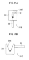
- Figs. 11A and 11B show seating plates 34 for different types of styluses 31 B and 31C according to modifications of the present invention.
- the seating plate 34 may have a notch 34E having a curved central axis M, as in the stylus 31B shown in Fig. 11A , and may also have an approximately V-shaped notch 34E, as in the stylus 31C shown in Fig. 11B .
- the flat spring 38 or the flat spring 82 is used as the elastic holding member, and the attachment-detachment mechanism is configured as a toggle joint.
- Different types of elastic holding members may be used to form the toggle joint.
- an elastic-force-generating part that includes an elastic member such as a spring plunger may also be used, as the elastic holding member.
- the spring plunger includes a coil spring, a cylindrical case that accommodates the coil spring, and a movable member that is contained in the case and can advance or retreat in the longitudinal direction. An end of the movable member protrudes from the cylindrical case. When the protruding end is pressed into the case by an external force, the coil spring is compressed, and the resultant repulsive force is applied to the movable member.
- the toggle joint operation is implemented as performed by the flat spring 38.
- the spring plunger rotates, compressing the coil spring.
- the movable member should press the seating plate 34 against the flat swinging member 37 by an elastic force generated by the compression.
- Fig. 12 is a perspective view of a stylus attachment-detachment mechanism of a lever type detector according to a third embodiment of the present invention.
- Fig. 13A is a partial side view of a flat swinging member 137 before the stylus is attached to a stylus holder
- Fig. 13B is a partial side view of a positional relationship between the flat swinging member 137 and a seating plate 134 after the stylus is attached.
- Fig. 13A and Fig. 13B correspond to Fig. 4A and 4B in the first embodiment.
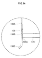
- Fig. 14 is enlarged partial side view of an area II in Fig. 13 .
- the detector has almost the same configuration as in the first embodiment except for the stylus holding mechanism.
- a flat spring 138 and a flat spring support 139 for supporting the flat spring 138 will be described below.
- the flat spring 138 is provided for the flat swinging member 137 for holding the seating plate 134 of the stylus 131.
- the flat swinging member 137 includes the wide plate 37A and the narrow plate 37B as in the first embodiment.
- the shaft body 36 is fixed to the wide plate 37A.
- the flat spring support 139 is formed continuously from the wide plate 37A of the flat swinging member 137. A position of the flat spring support 139 on the wide plate 37A is closer to the narrow plate 37B than a position of the shaft body 36.
- the flat spring support 139 is extended from the wide plate 37A parallel to the longitudinal direction of the shaft body 36.
- the flat spring 138 is fastened by a setscrew on the extended end of the flat spring support 139, like a cantilever.
- the flat spring 138 is screwed to the flat spring support 139 at a base end in the approximately parallel state to the wide plate 37A.
- a tip end of the flat spring 138 extends toward the shaft body 36.
- the flat spring 138 has a bend to the outside at the tip end.
- a width of the tip end of the flat spring 138 is wider than a width of the base end.
- the width of the tip end of the flat spring 138 is wider than the width P of the notch 34E (see Fig. 7A ) of the seating plate 134.
- the wide plate 37A and the seating plate 134 are placed side by side in the longitudinal direction of the shaft body 36.
- the three positioning balls 34C is provided between the seating plate 134 and the wide plate 37A.
- the positioning balls 34C function for positioning the seating plate 134, for maintaining the parallel relationship between the seating plate 134 and the flat swinging member 137, and for smoothly guiding the shaft body 36 to a center of gravity of the stylus 131 at the attachment of the stylus 131.
- the seating plate 134 has two protrusions 34J protruding forward the flat spring 138.
- the protrusions 34J are formed on a flat face opposite to a flat face with the positioning balls 34C of the seating plate 134.
- the notch 34E of the seating plate 134 is located between two protrusions 34J.
- Each protrusion 34J includes a single steel ball partially buried in the flat face of the seating plate 134.
- a cemented carbide ball may also be used for the protrusion 34J as the positioning ball 34C in the first embodiment.
- the pair of depressed parts 34F in the first embodiment become unnecessary for the seating plate 134, since the flat spring 138 contacts with the protrusions 34J and holds the stylus 131.
- a fundamental operation of the attachment-detachment mechanism is common to the first embodiment. Some differences will be mainly described below with reference to Figs. 13A and 13B .
- the shaft body 36 is guided along the notch 34E of the seating plate 134.
- the shaft body 36 and the flat spring support 139 are placed side by side in a guiding direction for guiding the shaft body 36.
- the flat spring support 139 is also inserted into the notch 34E followed the shaft body 36.
- a tip of the flat spring 138 comes into contact with the protrusions 34J. After that, the flat spring 138 is bended, and the tip of the flat spring 138 is pushed to the outside by the protrusions 34J.
- a distance between the wide plate 37A and the tip of the flat spring 138 is bigger than a state before guidance.
- the elastic force based on the elastic deformation of the flat spring 138 acts through the protrusions 34J to press the seating plate 134 against the flat swinging member 137. Consequently, a holding force for holding the stylus 131 is generated.
- pushing the tip of the flat spring 138 to the outside means pushing in a direction in which the tip end becomes far from the swinging member 137.
- the stylus holding mechanism is configured with the simple flat spring mechanism for attachment-detachment of the stylus
- the attachment-detachment mechanism can have a still lower weight, improve steadiness of automatic stylus exchanging and its usefulness.
- a convex part 139A is formed in the extended end of the flat spring support 139 at a position closest to the shaft body 36.
- the convex part 139A extends slightly more than another part of the flat spring support 139. Therefore in a state in which the flat spring 138 is fastened by a setscrew on the flat spring support 139, the flat spring 138 is elastically deformed slightly to the outside by the convex part 139A.
- the flat spring 138 is classified into three parts which have a narrow part 138A including its base end and a wide part 138B and a tip end 138C bended to the outside. A position in which the flat spring 138 contacts the convex part 139A is the approximate middle of the wide part 138B.
- the convex part 139A is provided for the support 139, in the state before stylus attachment, the flat spring 138 is elastically deformed. Therefore when the stylus 131 is attached, the flat spring 138 is elastically deformed still more and the strong elastical force acts against the stylus 131. As a result, although the elastic deformation of the flat spring 138 based on the stylus attachment is slight, a predetermined holding force is generated so as to hold the stylus 131.
- FIG. 15 is a perspective view of a positional relationship between the stocker 163 and the detector 130 before the stylus 131 is taken out of the stocker 163.
- Fig. 15 corresponds to Fig. 9A in the first embodiment.
- Figs. 16A to 16C are views illustrating a procedure for exchanging the stylus 131.
- Fig. 16A is a perspective view showing a state before the stylus 131 is taken out of the stocker 163.
- Fig. 16B is a perspective view showing a state in which the stylus 131 is attached to the flat swinging member 137.
- Fig. 16C is a perspective view showing a state after the stylus 131 is taken out of the stocker 163.
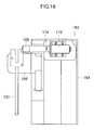
- Each stocker 163 includes a rectangular stocker body 164 and an upper support 165 and a lower support 166.
- the stocker body 164 is configured to move the upper support 165.
- the upper support 165 forms as a part which can move forward and backward for preventing the stylus from moving in the present invention.
- the lower support 166 forms as a locked part in the present invention.
- the lower support 166 will be described below with reference to Figs. 16C .
- the lower support 166 projects in the negative X direction from a stocker body 164.
- the projecting portion of the lower support 166 is formed flatly.
- the flat face of the lower support 166 is parallel to the x-z plane.
- An approximately square cut portion is provided for the lower support 166 from the positive Z direction edge in the negative Z direction.
- the lower support 166 is classified into three parts which have an inner side plate 166A and an outer side plate 166B and a lower plate 166C.
- the cut portion is positioned between the two side plates 166A, 166B.
- the lower plate 166C is positioned under the cut portion and connects the two side plates 166A, 166B.
- two upper locking parts 34L having an L-shaped cross section and a single lower locking part 34K are provided for the seating plate 134 of the stylus 131. These locking parts 34L, 34K are respectively formed integrally with the seating plate 134.
- the notch 34E of the seating plate 134 is positioned between two upper locking parts 34L.
- a groove extend in the Z direction is formed in the upper locking part 34L so as to lock the side plate 166A, 166B.
- the lower locking part 34K is formed in the seating plate 134 at a offset position from the notch 34E to the negative Z direction.
- the lower locking part 34K has three grooves. Two grooves are formed on the sides in the positive and negative X direction. Other groove is formed on the side in the negative Z direction. In other words, two grooves extended in the Z direction lock the side plates 166A, 166B, and one groove extended in the x direction locks the lower plate 166C.
- the upper support 165 and the lower support 166 are placed side by side in a Z direction.
- the upper support 165 projects in the negative X direction from the stocker body 164.
- a projecting amount of the upper support 165 is approximately same to a projecting amount of the inner side plate 166A of the lower support 166.
- the upper support 165 is formed to advance or retreat in the X direction.
- Figs. 17A and 17B are views illustrating an operation of the upper support 165 at the taking the stylus 131 from the stocker 163.
- Fig. 17A is a perspective view showing the upper support 165 which has moved backward to a releasing position.
- Fig. 17B is a perspective view showing the upper support 165 which has moved forward to a locking position.
- Figs. 18 is a back view showing the stocker body 164 without a side cover 168 and showing a driver 172 connecting the upper support 165.
- the upper support 165 is supported by a tip end of a drive shaft 174 provided for the driver 172 of solenoid type, and can advance or retreat in the X direction. At the locking position, as in Fig. 17B , a tip end of the upper support 165 can lock the upper locking part 34L closer to the stocker body 164.
- a moving distance of the drive shaft 174 is a few millimeters.
- the detector drive mechanism 40 is driven and the stylus exchange operation between the stylus holder 32 and the exchange rack 60 is executed.
- the lever type detector 130 mounting no stylus is positioned relative to the stylus 131 accommodated in the stocker 163 so that the longitudinal direction of the stylus 131 become same to the central axis of the stylus holder 132.
- the detector 130 can move in the negative Z direction by the vertical motion drive mechanism 43, so as to approach the stocker 163.
- the shaft body 36 of the stylus holder 132 is guided to the center of gravity of the stylus 131. Therefore the seating plate 134 is attached to the flat swinging member 137 of the stylus holder 132 (see Fig. 16B ).
- the detector 130 moves in the positive Z direction so as to be far from the exchange rack 60.
- the grooves provided for the locking parts 34L, 34K of the stylus 131 release the side plates 166A, 166B and the lower plate 166C of the stocker 163, and the stylus holder 132 can take the stylus 131 from the exchange rack 60 (see Fig. 16C ).
- the detector 130 moves as shown in Fig. 16C , 16B, 16A in this order.
- the upper support 165 moves to the locking position from the releasing position by the driver 172 of solenoid type.
- the detector 130 moves in the positive Z direction, becomes far from the exchange rack 60 by the vertical motion drive mechanism 43.
- the stylus holder 132 moves in the positive Z direction in the state in which the stylus 131 is accommodated in the stocker 163.
- the stylus 131 detached from the detector 130 is stored in the exchange rack 60.
- the moving direction of the detector 130 in the stylus exchange operation become one direction in the Z direction only. Since the moving in the X direction is unnecessary for the stylus exchange operation, the stylus exchanger can have a still more simplified construction.
- the present invention can be applied not only to roundness measuring machines but also to a wide range of surface-property measuring machines, such as surface roughness testers and contour-shape measuring machines.
Landscapes
- Physics & Mathematics (AREA)
- General Physics & Mathematics (AREA)
- A Measuring Device Byusing Mechanical Method (AREA)
Abstract
Description
- This application is based on and claims the benefits of priority from Japanese Patent Application No.
2010-002055 filed on January 7, 2010 2010-269929 filed on December 3, 2010 - The present invention relates to lever-type detectors, styluses, and automatic stylus exchangers used in surface-property measuring machines, and more specifically, to improvements to a lever-type detector having a detachable stylus and an automatic stylus exchanger for attaching and detaching the stylus to and from the detector automatically.
- A known surface roughness tester brings its stylus into contact with the surface of a workpiece, moves the stylus along a surface of the workpiece, detects the displacement of the stylus caused by the surface roughness, and determines the surface roughness from the displacement (refer to Japanese Patent Application Publication No.
2000-74616 - The lever-type detector mounted to the surface roughness tester illustrated in
Figs. 3 and9 in Japanese Patent Application Publication No.2000-74616 - Since styluses in various shapes are prepared beforehand for workpiece measurement portions having different shapes, in addition to the usual stylus, the operator of the surface roughness tester exchanges the stylus to one suitable for a workpiece measurement portion before starting measurement. For example, before starting measurement, the operator sets up a bore testing stylus to measure the surface roughness of a bore or sets up a deep-groove testing stylus having a long length to measure the surface roughness of a deep groove.
- Besides the surface roughness tester, surface-property measuring machines such as a roundness measuring machine and a contour-shape measuring machine also have styluses in different shapes prepared for various workpiece measurement portions to deal with diversified kinds of measurement.
- Conventionally, the operator exchanges the stylus. To do so, the operator temporarily stops the measurement, removes the current stylus from the detector, attaches a new stylus to the detector, and resumes the measurement.
- In the conventional stylus exchanging procedure, the operator must stop the measurement temporarily and must detach the current stylus and attach a new one by hand. This interrupts the measurement for a long period of time and places a great deal of burden on the operator who exchanges the stylus. Accordingly, demand for automatic, unattended measurement by surface-property measuring machines has been growing in recent years.
- The automatic probe changer used with three-dimensional measuring machines and the like could be applied to a surface-property measuring machine. The measuring machine may be equipped with an exchange rack storing different types of styluses, so that the stylus on the detector can be exchanged automatically.
- One problem which is common to the conventional manual stylus exchange and the automatic stylus exchange by using the exchange rack is that the exchanged stylus of a different type upsets the lever-type detector and changes the measuring force of the detector. The measuring force is a force exerted on the workpiece by the stylus during measurement. In particular, precise measurement requires balance adjustment of the stylus after it is exchanged. Therefore, the detector must have a mechanism for performing automatic balance adjustment after the stylus is automatically exchanged by using the exchange rack.
- In view of the foregoing problems, an object of the present invention is to provide a lever-type detector, a stylus, and an automatic stylus exchanger that allow styluses of different types to be exchanged automatically and reduce the burden of exchanging the styluses of different types for the lever-type detector.
- The foregoing object is achieved in one aspect of the present invention through the provision of a lever-type detector including a stylus having a contact part that comes into contact with a workpiece; a stylus holder that supports the stylus swingably; and displacement detection means for detecting a swinging displacement of the stylus; and the lever-type detector obtains the swinging displacement of the stylus in order to measure a surface property of the workpiece. The stylus includes a long stylus body having the contact part at a tip end and a seating that is disposed in a base end of the stylus body and is detachable from the stylus holder. The stylus holder includes a shaft body that serves as the center of swinging of the stylus. The seating contains the position of the center of gravity of the whole stylus separated from the stylus holder and has a notch for guiding the shaft body to the center of gravity of the stylus when the stylus is attached. In a state in which the shaft body is guided to the center of gravity through the notch, the seating is detachably held by the stylus holder, and the stylus becomes swingable about the shaft body. The shape of the notch may be an approximately U shape, an approximately V shape, or an approximately L shape, and is not limited.
- The shaft body provided for the stylus holder may be supported by the stylus holder rotatably or may be fixed to the stylus holder. In the latter case, a swinging member, described later, rotates about the central axis of the shaft body fixed.
- It is preferred in the above-described lever-type detector that the seating of the stylus include a counterbalance for adjusting the position of the center of gravity such that the center of gravity of the whole stylus is placed in the notch of the seating.
- It is preferred that the lever-type detector further include styluses of different types prepared for measurement of different portions of the workpiece, each of the styluses have a locking part that can lock a part provided for an exchange rack that accommodates the styluses and allows the styluses to be taken out; and the locking part be disposed in the seating of each of the styluses in a position offset with respect to the counterbalance in the direction of a swinging axis of the shaft body.
- The locking part disposed in the seating locks the part provided for the exchange rack. The held stylus is detached from the stylus holder. These two operations are executed in close coordination. More specifically, to detach the stylus from the stylus holder, the stylus holder is moved toward the exchange rack to make the locking part engage with the part provided for the exchange rack. Then, while this engagement is maintained, when the detector is moved away from the exchange rack, the seating is detached from the stylus holder, allowing the stylus to be stored in the exchange rack. Conversely, to mount a stylus to the stylus holder, the stylus holder is moved toward the exchange rack to guide the shaft body of the stylus holder to the center of gravity of the stylus, mounting the seating of the stylus to the stylus holder. Then, the stylus holder is moved in a direction in which the locking condition of the locking part is released to take out the stylus from the exchange rack.
- It is preferred in the lever-type detector that the stylus holder include a swinging member supported by the shaft body; in a state in which the shaft body is guided to the center of gravity of the stylus, the swinging member and the seating be placed side by side along the direction of a swinging axis of the shaft body; and the swinging member include an elastic holding member for holding the seating by pressing it against the swinging member with an elastic force and a support for supporting the elastic holding member.
- It is preferred that the elastic holding member be rotatably supported by the support at a base end, and when the stylus is attached to the stylus holder, the elastic holding member be pressed at a tip end by the seating, generate elastic deformation while rotating, and use the resultant elastic force to hold the seating by pressing it against the swinging member.
- It is preferred that the elastic holding member be cantilevered by the support at a base end, and when the stylus is attached to the stylus holder, the elastic holding member be pressed at a tip end to become far from the swinging member by the seating, generates elastic deformation based on a bend, and use the resultant elastic force to hold the seating by pressing it against the swinging member. In a state in which the stylus is attached to the stylus holder, it is preferred that the seating have the notch located between two protrusions provided for the seating protruding forward the elastic holding member. And the elastic holding member be flat and cantilevered by the support at a base end, and pressed at a tip end to become far from the swinging member by the protrusions.
- It is preferred that in a state in which the stylus is attached to the stylus holder, the support be extended in the direction of the swinging axis of the shaft body from the swinging member through the notch and support the elastic holding member at a extended tip end.
- It is preferred that at least three balls be placed between the seating and the swinging member in at least three positions that are not in a straight line, and the balls be used to position the seating with respect to the swinging member in the direction of the swinging axis of the shaft body. And it is preferred that at least two of the balls be rotatably supported by the seating, and when the stylus is attached to the stylus holder, the balls roll on a groove formed in the swinging member along the direction in which the shaft body is guided to the center of gravity.
- The foregoing object is achieved in another aspect of the present invention through the provision of a stylus detachably attached to the above-described lever-type detector.
- The foregoing object is achieved in still another aspect of the present invention through the provision of an automatic stylus exchanger including the above-described lever-type detector; an exchange rack that accommodates styluses of different types prepared for different portions to be measured in a workpiece and allows the styluses to be taken out; a detector drive mechanism for moving the lever-type detector in a direction for approaching or separating from the exchange rack; and a controller. When a stylus exchange command is given, the controller controls the detector drive mechanism and performs a stylus exchange operation between the stylus holder and the exchange rack.
- It is preferred that the seating of the styluses be flat, the exchange rack comprise a locked part and a part for preventing. The locked part is projecting in a moving direction of the lever-type detector in order to guide the stylus locked by a locking part disposed in the seating into a accommodating position when the lever-type detector moves in a direction orthogonal to the direction in which the shaft body is guided to the center of gravity of the stylus on a flat face provided for the seating. And in a state in which the stylus is in the accommodating position, the part for preventing the stylus from moving in the direction in which the shaft body is guided to the center of gravity of the stylus. As a result, only the stylus is accommodated by the exchange rack when the lever-type detector moves in a direction in which the shaft body is guided to the center of gravity of the stylus.
- It is preferred that the seating of the styluses be flat, the exchange rack comprise a locked part and a part for preventing. The locked part is projecting in a moving direction of the lever-type detector in order to guide the stylus locked by a locking part disposed in the seating into a accommodating position when the lever-type detector moves in a direction in which the shaft body is guided to the center of gravity of the stylus on a flat face provided for the seating. And in a state in which the stylus is in the accommodating position, the part for preventing the stylus from moving in the direction in which the shaft body is guided to the center of gravity of the stylus. The part for preventing is provided so as to move forward and backward between a position for locking the seating in order to prevent the stylus from moving and a position for releasing a lock of the seating. As a result, in a state in which a locking position of the part is kept, only the stylus is accommodated by the exchange rack when the lever-type detector moves in a direction in which the shaft body is guided to the center of gravity of the stylus.
- A lever-type detector according to the present invention has a seating integrally formed with a stylus body at a base end of a stylus, opposite to a contact part of the stylus. The seating of the stylus is held by a stylus holder detachably. The stylus body and the seating may be produced separately and then integrated.
- According to the present invention, the seating of the stylus has a notch used to guide a shaft body, which serves as a swinging axis of the stylus, to the center of gravity of the stylus. Attachment through the notch allows the shaft body to reach the center of gravity of the stylus. Since the center of gravity of any stylus is placed on the same axis as the shaft body, which is the center of swinging of the lever-type detector, even after the stylus is changed to a different type, the whole stylus, including the swinging member, is kept in good balance, and measurement can be continued with the same measuring force as that used before the exchange. This eliminates the need for stylus balance adjustment after the exchange, especially in precise measurement, and consequently, the detector does not need to include a balance adjustment mechanism.
- According to the present invention, the seating has a counterbalance for adjusting the position of the center of gravity to bring the center of gravity of the whole stylus into the notch of the seating. When two styluses differing in stylus length, shape of the contact part, and material are used, if the seating of a first stylus is formed to fit the center of gravity of the first stylus and if the seating formed for a second stylus is the same as the seating for the first stylus, the center of gravity of the second stylus can be set in the same position as set by the seating for the first stylus because of the counterbalance disposed on the seating of the second stylus. The counterbalance allows standardization of the basic shape of the seating among styluses of different types.
- According to the present invention, since a lock part provided in the seating is offset in the direction of the swinging axis with respect to the counterbalance of the same seating, the counterbalance can be scaled up or down more freely, and consequently a stylus of a special shape can be produced more easily.
- The present invention employs a mechanism for holding the stylus with an elastic force. Since the swinging member is provided with an elastic holding member for holding the seating by pressing it against the swinging member with an elastic force, the stylus holding mechanism can have a simplified configuration and lower weight in comparison with a magnetic holding mechanism.
- The elastic holding member has its base end rotatably supported by a support. When the stylus is attached to the stylus holder, it is pressed by the seating at its tip end, exhibits elastic deformation as it rotates, and holds the seating by pressing it against the swinging member with the elastic force. Therefore, the seating can be held by the swinging member just by inserting it, and the seating can be detached from the swinging member just by pulling it. The stylus holding mechanism configured as a so-called toggle joint facilitates the exchange process.
- The elastic holding member does not produce an elastic force before its tip is pressed by the seating. When its tip is pressed by the seating, the elastic holding member rotates, exhibiting elastic deformation, and the elastic force exerted on the seating increases gradually. When the elastic holding member is rotated to a predetermined position, the seating is held by the swinging member with a predetermined holding force. With the toggle joint as described here, the seating of the stylus comes into contact with the tip of the elastic holding member, moves a short distance further, and is then completely held by the swinging member. By positioning the seating and the swinging member during the short-distance movement, for example, the stylus can be held after it is accurately positioned.
- According to the present invention, the stylus holding mechanism is configured with a simple flat spring mechanism for attachment-detachment of the stylus instead of the toggle joint. Consequently, the stylus holding mechanism can have a still lower weight, improve steadiness of automatic stylus exchanging and usefulness.
- According to the present invention, a plurality of balls are provided in at least three positions that are not in a straight line between the seating and the swinging member. With the balls, the seating is positioned with respect to the swinging member, so that the seating is accurately positioned in the direction of the central axis of the shaft body.
- Since at least two of the balls are rotatably supported by the seating and are guided along a groove formed in the swinging member, the shaft body is guided accurately to the center of gravity of the stylus. Accordingly, the positional relationship between the swinging member and the seating can be reproduced accurately, and unevenness in measured values caused by exchanging the stylus are reduced.
- An automatic stylus exchanger according to the present invention eliminates the need for stylus balance adjustment in automatic exchange, allows measurement to be continued with the same measuring force even after the stylus is exchanged with one of a different type, and has other advantages, as described earlier.
- A lever-type detector and a stylus according to the present invention can reduce the burden of manual exchange of a plurality of styluses, and an automatic stylus exchanger according to the present invention can automatically exchange styluses of different types in a lever-type detector.
-
Fig. 1 is a perspective view of a roundness measuring machine according to a first embodiment of the present invention. -
Fig. 2A is a perspective view of a detector in the roundness measuring machine, andFig. 2B is a perspective view showing the internal structure of the detector. -
Fig. 3A is a perspective view of a swinging member of the detector, andFigs. 3B and3C are perspective views of a stylus from different angles. -
Fig. 4A is a partial sectional view of the detector before the stylus is attached to a stylus holder, andFig. 4B is a partial sectional view after the stylus is attached. -
Fig. 5 is a perspective view showing a flat spring of the stylus holder supported by the swinging member. -
Figs. 6A to 6C are enlarged partial sectional views of an area I inFig. 4B .Fig. 6A shows an initial state when the flat spring starts rotating;Fig. 6B shows the flat spring rotated by a predetermined angle; andFig. 6C shows the flat spring rotated until a predetermined holding power is generated. -
Figs. 7A and 7B illustrate the positions of the centers of gravity in different types of styluses. -
Fig. 8 is a perspective view of the roundness measuring machine shown inFig. 1 with an exchange rack, seen from a different angle. -
Figs. 9A and 9B are views illustrating a procedure for exchanging the stylus in the machine shown inFig. 8 .Fig. 9A is a perspective view showing a state before the stylus is taken out of the exchange rack.Fig. 9B is a perspective view showing a state after the stylus is taken out. -
Figs. 10 A and 10B are partial side views of a stylus holder of a detector according to a second embodiment.Fig. 10A shows a state before a stylus is attached, andFig. 10B shows a state after the attachment. -
Figs. 11A and 11 B show seatings for different types of styluses according to modifications of the present invention. -
Fig. 12 is a perspective view of a stylus attachment-detachment mechanism of a lever type detector according to a second embodiment of the present invention. -
Fig. 13A is a partial side view of the swinging member before the stylus is attached to a stylus holder, andFig. 13B is a partial side view of the positional relationship between the swinging member and the seating after the stylus is attached. -
Fig. 14 is enlarged partial side view of an area II inFig. 13 . -
Fig. 15 is a perspective view of the positional relationship between a stocker and a detector before the stylus is taken out of the stocker. -
Figs. 16A to 16C are views illustrating a procedure for exchanging the stylus.Fig. 16A is a perspective view showing a state before the stylus is taken out of the stocker.Fig. 16B is a perspective view showing a state in which the stylus is attached to the swinging member.Fig. 16C is a perspective view showing a state after the stylus is taken out of the stocker. -
Figs. 17A and 17B are views illustrating a operation of an upper support of the stocker.Fig. 17A is a perspective view showing a releasing position.Fig. 17B is a perspective view showing a locking position. -
Figs. 18 is a back view showing a driver of the upper support of the stocker. -
Fig. 1 is a perspective view of a roundness measuring machine according to a first embodiment of the present invention. - As shown in
Fig. 1 , the roundness measuring machine of the first embodiment includes abase 10, aturntable 20 provided on one side of the base 10 to turn about the vertical central axis L and to support a workpiece W on its top surface, a lever-type detector 30, adetector drive mechanism 40 that moves the lever-type detector 30 toward or away from theturntable 20 in the direction of the vertical central axis L and a direction orthogonal to the vertical central axis L, and acontroller 50. - The
turntable 20 contains a turntable drive mechanism 21, which is not shown in the figure. The turntable drive mechanism 21 can turn theturntable 20 around the vertical central axis L. The turntable drive mechanism 21 includes a motor for turning theturntable 20 or a mechanism for transferring the rotation of a motor through a decelerator to theturntable 20. - The lever-
type detector 30 includes astylus 31 to be brought into contact with the workpiece W and astylus holder 32 that holds thestylus 31 detachably and detects the displacement of thestylus 31 as an electrical signal. Thestylus 31 is supported to swing about a swinging axis provided in thestylus holder 32. Therefore, the detected displacement of thestylus 31 is the amount of rotational displacement of thestylus 31. However, since the amount of displacement is tiny with respect to the turning radius of thestylus 31, the detected displacement becomes the amount of displacement in a direction orthogonal to the longitudinal direction of thestylus 31. - The
detector drive mechanism 40 includes acolumn 41 provided upright on the other side of thebase 10, a verticalmotion drive mechanism 43 that moves avertical slider 42 in the vertical direction (Z direction) along thecolumn 41, a first horizontalmotion drive mechanism 45 that slides aslide arm 44 toward or away from theturntable 20 in the direction (X direction) orthogonal to the vertical central axis L, with respect to thevertical slider 42, adetector arm 46 that is provided at an end of theslide arm 44 to hold thedetector 30, and a rotational motion drive mechanism 47 (not shown in the figure) that turns thedetector arm 46 around the sliding axis of theslide arm 44 to change the orientation of thedetector 30. - The vertical
motion drive mechanism 43 can have any structure so long as it can move thevertical slider 42 up and down. For example, the verticalmotion drive mechanism 43 can be a feed mechanism that includes a ball thread shaft standing upright in the vertical direction in thecolumn 41, a motor for turning the ball thread shaft, and a nut coupled with thevertical slider 42 engaged with the ball thread shaft. - The first horizontal
motion drive mechanism 45 can have any structure so long as it can move theslide arm 44 toward or away from theturntable 20 in the direction orthogonal to the vertical central axis L. For example, the first horizontalmotion drive mechanism 45 can be a mechanism in thevertical slider 42, which includes a rack formed along the longitudinal direction of theslide arm 44 and a pinion that engages with the rack, a motor for turning the pinion, and the like. - When a measurement program stored in a program storage section 51 of the
controller 50 gives a measurement command to thecontroller 50, thedetector drive mechanism 40 is driven. The verticalmotion drive mechanism 43 and the first horizontalmotion drive mechanism 45 move thedetector 30 toward the workpiece W, and thestylus 31 of thedetector 30 is brought into contact with the workpiece W. When necessary, the rotationalmotion drive mechanism 47 is operated to change the orientation of thedetector 30. If theturntable 20 turns in this state, thestylus 31 of thedetector 30 is displaced in accordance with the roundness of the workpiece W. The displacement of thestylus 31 is detected by thestylus holder 32 as an electrical signal and is then taken into thecontroller 50. Thecontroller 50 stores the measurement data in a data storage section 52, calculates the roundness from the data, displays the result on a display unit 53, and prints out the result, if necessary. - A characteristic stylus attachment-detachment mechanism of the
detector 30 according to the present invention will be described with reference toFigs. 2A to 7B .Fig. 2A shows a perspective view of thedetector 30, andFig. 2B shows the internal structure. - As shown in
Fig. 2A , in thedetector 30, thestylus 31 is supported to swing about a swing bearing 32A disposed in thestylus holder 32. Thedetector 30 also has a mechanism for attaching and detaching thestylus 31. Accordingly, as shown inFig. 2B , thedetector 30 has a flat swingingmember 37 that is supported to turn around ashaft body 36, which serves as a swinging axis. The flat swingingmember 37 is configured to hold thestylus 31 detachably. -
Figs. 3B and3C show perspective views of thestylus 31 from different angles. Thestylus 31 includes along stylus body 33 having acontact part 33A at its tip end and aseating plate 34 integrally formed with the base end of thestylus body 33. - The
stylus body 33 has a long cylindrical shape and two cemented carbide balls, which arecontact parts 33A, fixed in one end of the cylinder. The two cemented carbide balls are half buried in the side face of the cylinder end at intervals of 180 degrees. The illustratedstylus 31 is just one example of various styluses. Thestylus bodies 33 of thevarious styluses 31 have different longitudinal lengths and different cylindrical diameters. Some styluses have just a single cemented carbide ball buried at the cylinder end as thecontact part 33A. The shape of thecontact parts 33A is not limited to a sphere and can be a circular cone having a spherical tip. The material of thecontact parts 33A can be sapphire or the like. - The
seating plate 34 is an approximately rectangular plate, and its central axis and the central axis of thestylus body 33 lie on a single straight line. Theseating plate 34, which corresponds to a seating in the present invention, includes abody 34A, two lockingparts 34B having different lengths, and threesteel positioning balls 34C (seeFig. 3C ). - As shown in
Fig. 7A , the shape of theseating plate 34 is determined so as to place the center of gravity of thewhole stylus 31, which includes both theseating plate 34 and thestylus body 33, over theseating plate 34. The center of gravity of thestylus 31 is indicated by a black dot inFig. 7A . - The
body 34A of theseating plate 34 has an approximatelyU-shaped notch 34E in its flat face. Thenotch 34E is formed to enclose the center of gravity of thestylus 31, as shown inFig. 7A . In other words, the center of gravity of thewhole stylus 31 is positioned in the approximatelyU-shaped notch 34E. The width P in the direction orthogonal to the central axis M of thenotch 34E is greater than the diameter of thecylindrical shaft body 36 of thestylus holder 32. Since the central axis M of thenotch 34E and the central axis of thestylus body 33 lie on a single straight line, when thestylus 31 is attached to thestylus holder 32, thenotch 34E can guide theshaft body 36 to the center of gravity. Thenotch 34E in this embodiment is approximately U-shaped but can have any shape, such as an approximate V shape or an approximate L shape, so long as theshaft body 36 can be guided to the center of gravity. - As shown in
Figs. 3B and3C , an axis N is set to pass through the center of gravity of thewhole stylus 31 and is parallel to the thickness direction of theseating plate 34. With respect to the axis N of the center of gravity, thenotch 34E is formed by cutting theseating plate 34 from a side thereof (above in the figure) to the axis N of the center of gravity of the stylus until the axis N of the center of gravity penetrates through theseating plate 34 without touching thebody 34A. - The
notch 34E has a pair ofdepressed parts 34F in two sides facing each other inside the U shape. The width Q of the pair ofdepressed parts 34F is greater than the width P of thenotch 34E (seeFig. 7A ). Thedepressed parts 34F are formed along the central axis M of thenotch 34E, not along the whole notch but from an upper opening inFig. 7A to approximately the center of thenotch 34E. As shown inFigs. 3B and3C , thedepressed parts 34F are formed along the axis N of the center of gravity, not across the entire thickness of theseating plate 34 but from the surface in which the lockingparts 34B are provided to a position of about 80% of the thickness of theseating plate 34. Therefore, as shown in an enlarged view inFig. 6C , thedepressed parts 34F have firstinternal faces 34G and secondinternal faces 34H. The firstinternal faces 34G of thedepressed parts 34F are orthogonal to the central axis M of thenotch 34E, and the secondinternal faces 34H are orthogonal to the axis N of the center of gravity of thestylus 31. - As shown in
Fig. 3C , thepositioning balls 34C are rotatably supported in one flat face of theseating plate 34. The threepositioning balls 34C are placed in three different positions, and two of them are placed on one side of thenotch 34E, and another one of them is placed on another side of thenotch 34E. In the state in which theseating plate 34 is put into thestylus holder 32 and thestylus 31 is attached, the threesteel positioning balls 34C come between theseating plate 34 and the flat swingingmember 37 of thestylus holder 32. Therefore, the threepositioning balls 34C function as positioning means for positioning theseating plate 34 with respect to the flat swingingmember 37 in the direction of the central axis of theshaft body 36 and for maintaining the parallel relationship between theseating plate 34 and the flat swingingmember 37. - The two
positioning balls 34C are placed side by side parallel to the central axis M (seeFigs. 7A and 7B ) of the approximatelyU-shaped notch 34E. When thestylus 31 is attached, the twopositioning balls 34C roll along a V-shapedgroove 37C formed in the flat swingingmember 37 of thestylus holder 32. - The
single positioning ball 34C disposed on the other side of thenotch 34E in theseating plate 34 rolls along a positioningflat face 37D formed parallel to the V-shapedgroove 37C. - As shown in
Fig. 2A and 2B , thestylus holder 32 includes aholder body 35, theshaft body 36, which is supported by theholder body 35, the flat swingingmember 37, which can turn around theshaft body 36, a flat spring 38 (not shown in the figure) for holding theseating plate 34 of thestylus 31 by an elastic force, aflat spring support 39 for supporting theflat spring 38, displacement detection means 71 (not shown in the figure) for detecting the angular displacement of the flat swingingmember 37, and turning force providing means 72 (not shown in the figure) for providing a turning force to the flat swingingmember 37. - The
holder body 35 is approximately cylindrical and has a hollow internal space where the flat swingingmember 37, the displacement detection means 71, and the turning force providing means 72 are placed. The base end (upper end in the figure) of the approximate cylinder is fixed to thedetector arm 46 shown inFig. 1 . The other end of the approximate cylinder has a notch having an approximately U-shaped cross section so that the flat swingingmember 37 and thestylus 31 turning together about theshaft body 36 do not touch it. The approximately U-shaped cross section is the cross-sectional shape of theholder body 35 cut away in a plane parallel to both the central axis of the approximatelycylindrical holder body 35 and the swinging axis of theshaft body 36. - The central axis of the
shaft body 36 is parallel to a direction orthogonal to the central axis of theholder body 35. Theshaft body 36 is supported rotatably near the other end of theholder body 35. Theshaft body 36 may be supported in a fixed position by theholder body 35. In that case, the flat swingingmember 37 is supported to rotate about the central axis of theshaft body 36. -
Fig. 3A shows a perspective view of the flat swingingmember 37.Fig. 4A shows a partial sectional view of the flat swingingmember 37 and theseating plate 34 before thestylus 31 is attached to thestylus holder 32.Fig. 4B shows another partial sectional view after thestylus 31 is attached. - The flat swinging
member 37 includes awide plate 37A where thestylus 31 is attached and theshaft body 36 is fixed and anarrow plate 37B (not shown in the figure) integrally formed with thewide plate 37A. After attachment, as shown inFig. 4B , thewide plate 37A and theseating plate 34 are placed side by side in the longitudinal direction of theshaft body 36. - The rotational displacement of the
narrow plate 37B is detected by the displacement detection means 71. A differential transformer is used as the displacement detection means 71. Any device that does not apply a load on thestylus 31, such as a distortion gauge or a capacitance sensor, may also be used. - The turning force providing means 72 gives the
narrow plate 37B a turning force, causing it to turn around theshaft body 36. A spring is used as the turning force providing means 72. An electric motor or an actuator that includes a voice coil formed of a magnet and a coil may also be used. - As shown in
Fig. 3A , theflat spring support 39 is formed continuously from thewide plate 37A. The position of theflat spring support 39 is a position in thewide plate 37A, on thenarrow plate 37B side of theshaft body 36. As shown in the cross-sectional view inFig. 4A , theflat spring support 39 includes a first supportingmember 39A that extends from thewide plate 37A in the longitudinal direction of theshaft body 36 and a second supportingmember 39B that extends toward theshaft body 36, like a cantilever, from the projecting end of the first supportingmember 39A. As shown inFig. 5 , a flatspring shaft material 39C is fixed at the tip of the second supportingmember 39B to support theflat spring 38 rotatably. The flatspring shaft material 39C is parallel to a direction orthogonal to the swinging axis of the flat swingingmember 37 and is also parallel to the width direction of thewide plate 37A. - The
flat spring 38 includes afirst spring part 38A and asecond spring part 38B and has an approximately L-shaped bend. One end of thefirst spring part 38A is wound around the flatspring shaft material 39C of theflat spring support 39 by almost a single winding so that theflat spring 38 can rotate around theflat spring support 39. - In the state before the
stylus 31 is attached, thefirst spring part 38A extends from the flatspring shaft material 39C toward thewide plate 37A, as indicated by a solid line inFig. 5 , and thesecond spring part 38B extends from the other end of thefirst spring part 38A toward theshaft body 36, parallel to the surface of thewide plate 37A. - The operation of the attachment-detachment mechanism will be described with reference to
Figs. 4A, 4B ,6A, 6B , and6C .Figs. 6A to 6C are enlarged views of the area I inFig. 4B . - As shown in
Figs. 4A and 4B , attachment of thestylus 31 by moving thestylus holder 32 toward thestylus 31 at rest, will now be described. If the operator were attaching thestylus 31 by hand, he would bring thestylus 31 toward thestylus holder 32 at rest, but the operation of the attachment-detachment mechanism is substantially the same. - As shown in
Fig. 4A , thestylus holder 32 is placed first in such a position with respect to thestylus 31 that the central axis of the approximatelycylindrical holder body 35 and the central axis M of thenotch 34E of the stylus 31 (seeFig. 7A ) lie on a single straight line and that the swinging axis of theshaft body 36 becomes parallel to the axis N of the center of gravity of thestylus 31. - The
stylus holder 32 is moved toward thestylus 31, and theshaft body 36 is inserted into the upper opening of thenotch 34E in theseating plate 34. In this process, if thepositioning balls 34C on theseating plate 34 are rolled on the V-shapedgroove 37C and the positioningflat face 37D of the flat swingingmember 37, theshaft body 36 is guided smoothly along the approximatelyU-shaped notch 34E to the center of gravity of thestylus 31, without touching theseating plate 34. - The
seating plate 34 is placed between thewide plate 37A of the flat swingingmember 37 and the second supportingmember 39B of theflat spring support 39. Following theshaft body 36, the first supportingmember 39A of theflat spring support 39 is inserted into the approximatelyU-shaped notch 34E (Fig. 4B ). - As shown in
Figs. 6A , before theshaft body 36 reaches the center of gravity of thestylus 31, the tip of the flat spring 38 (tip of thesecond spring part 38B) comes into contact with the firstinternal faces 34G formed in thedepressed parts 34F of thenotch 34E. The tip of theflat spring 38 is pushed by the firstinternal faces 34G, and theflat spring 38 starts rotating around the flatspring shaft material 39C. After theflat spring 38 rotates by a predetermined angle, the tip of theflat spring 38 comes into contact with the secondinternal faces 34H (Fig. 6B ) as well. The tip of theflat spring 38 moves to the corners between the firstinternal faces 34G and the secondinternal faces 34H. If the tip of theflat spring 38 is pushed further by the firstinternal faces 34G, elastic deformation of theflat spring 38 starts, and the angle formed by thefirst spring part 38A and thesecond spring part 38B decreases gradually. - As shown in
Fig. 6A , let the distance between the center of rotation of theflat spring 38 and the tip of theflat spring 38 be S. In the state in which theshaft body 36 is guided to the center of gravity of the stylus 31 (Fig. 6C ), the distance S decreases, and a certain amount of elastic deformation is obtained. As shown inFig. 6A , since the line connecting the center of rotation of theflat spring 38 and the tip of theflat spring 38 is approximately orthogonal to the flat face of the flat swingingmember 37, the elastic force of theflat spring 38 presses theseating plate 34 against the flat swingingmember 37 and generates a holding force, as indicated by an arrow. - While the
seating plate 34 is being inserted, theflat spring 38 can have two states, pressing theseating plate 34 and not pressing theseating plate 34, so that the flat swingingmember 37 can stably hold theseating plate 34 by the elastic force of theflat spring 38. - When the
seating plate 34 is pulled from the space between the flat swingingmember 37 and the second supportingmember 39B, theflat spring 38 works in reverse. Theseating plate 34 is detached from the flat swingingmember 37, and thestylus 31 can be easily removed from thestylus holder 32. - According to the present embodiment, because the
shaft body 36 passes the approximatelyU-shaped notch 34E formed in theseating plate 34 when the stylus is attached, theshaft body 36 can reach the center of gravity of thestylus 31. That is, if thestylus 31 is attached to thestylus holder 32, the center of gravity always lies on the same axis as theshaft body 36, regardless of the type ofstylus 31. Accordingly, even if thestylus 31 of a different type is attached to the flat swingingmember 37, thewhole stylus 31, including the flat swingingmember 37, is kept in good balance, and the measurement can be continued with the same measuring force as before the exchange. This eliminates the need for balance adjustment of thestylus 31 after the stylus is exchanged in precise measurement. - The
seating plate 34 can be held by the flat swingingmember 37 just by inserting it and can be detached from the flat swingingmember 37 just by pulling it. Thestylus 31 is detachable from thestylus holder 32. Since the flat swingingmember 37 can hold theseating plate 34 by the elastic force of theflat spring 38, the mechanism for holding thestylus 31 can have a simplified configuration and less weight in comparison with a magnetic holding mechanism. - At the attachment of the
stylus 31, when the tip of theflat spring 38 is first pressed by the firstinternal faces 34G of theseating plate 34, theflat spring 38 starts to elastically deform while rotating, and the generated elastic force presses the secondinternal faces 34H of theseating plate 34 against the flat swingingmember 37. Since the mechanism for holding thestylus 31 is configured as a so-called toggle joint, thestylus 31 can be exchanged easily. - This type of toggle joint does not produce the elastic force of the
flat spring 38 before the tip of theflat spring 38 comes into contact with the secondinternal faces 34H. After theflat spring 38 comes into contact with the secondinternal faces 34H, thestylus holder 32 advances a short distance further, and then the elastic force pressing the secondinternal faces 34H is maximized, completing the process of holding thestylus 31. Since theseating plate 34 and the flat swingingmember 37 can be positioned while thestylus holder 32 is advancing the short distance, thestylus 31 can be held in thestylus holder 32 after it is positioned accurately. - In the positioning of the
stylus 31 for attachment, the threepositioning balls 34C placed in at least three different positions, not in a straight line, between theseating plate 34 and the flat swingingmember 37 are used to position theseating plate 34 with respect to the flat swingingmember 37. Therefore, theshaft body 36 can be positioned accurately in the direction of the central axis. - During attachment, two of the three
balls 34C are guided along the V-shapedgroove 37C of the flat swingingmember 37, so that theshaft body 36 can be guided accurately to the center of gravity of thestylus 31. In other words, the central axis of theshaft body 36 agrees with the axis N of the center of gravity of thestylus 31, and the positional relationship between the flat swingingmember 37 and theseating plate 34 before the exchange can be reproduced accurately. - The number of
positioning balls 34C is not limited to three. At least threeballs 34C should be placed in three different positions, not in a straight line. At least two of theballs 34C should be provided to roll along the V-shapedgroove 37C. - The
positioning balls 34C need not be provided rotatably on theseating plate 34; they may be press-fitted or bonded to theseating plate 34. -
Fig. 7B shows the position of the center of gravity of adifferent stylus 31A likeFig. 7A . Thestylus 31A has an approximatelyU-shaped notch 34E in a direction orthogonal to the longitudinal direction of thestylus body 33, but the basic shape of aseating plate 34 is the same as that of theseating plate 34 inFig. 7A . Theseating plate 34 of thestylus 31A has acounterbalance 34D for adjusting the position of the center of gravity so that the center of gravity of thewhole stylus 31 A is placed in thenotch 34E of theseating plate 34. Since the center of gravity of the stylus of any type can be adjusted with thecounterbalance 34D disposed on theseating plate 34, the basic shape of theseating plate 34 can be standardized for different types of styluses. - The
stylus 31A shown inFig. 7B is called a crank stylus and is useful for measuring the internal surface of a narrow circumferential groove. In the crank stylus, thestylus body 33 has a small-diameter,short rod 33B at its tip, orthogonally to thestylus body 33, and acontact part 33C is formed in the end of theshort rod 33B. The shape of the contact part 33c is a circular cone shape having a sphere at the tip. - Automatic exchange of the
stylus 31 of thedetector 30 will be described next. -
Fig. 8 is a perspective view of the roundness measuring machine shown inFig. 1 with anexchange rack 60 mounted thereto, seen from a different angle. This roundness measuring machine differs from the machine shown inFig. 1 in the shape of thedetector arm 46, but has the same basic configuration as the machine shown inFig. 1 and uses an automatic stylus exchanger according to the present invention. -
Figs. 9A to 9C illustrate a procedure for exchanging thestylus 31.Fig. 9A shows a perspective view before thestylus 31 is taken out from theexchange rack 60, andFig. 9B shows a perspective view after thestylus 31 is taken out. - As shown in
Fig. 8 , theexchange rack 60 is disposed on the base 10 between theturntable 20 and thecolumn 41. The verticalmotion drive mechanism 43 and the first horizontalmotion drive mechanism 45 are configured to move thedetector 30 to the position of theexchange rack 60. - The
exchange rack 60 includes arack base 61, arack slider 62 that slides in the Y direction on therack base 61, and threestockers 63 standing upright on therack slider 62. InFig. 8 , afirst stocker 63A is positioned at an attachment-detachment location. As therack slider 62 moves, asecond stocker 63B and athird stocker 63C can be positioned at the location one at a time. Thesecond stocker 63B stores thedifferent stylus 31 A. - As shown in
Fig. 9A , eachstocker 63 includes arectangular stocker body 64 standing upright on therack slider 62 and anupper support 65 and alower support 66 fixed on thestocker body 64. Theupper support 65 forms a part is provided for preventing thestylus 31 from moving in the present invention. Thelower support 66 forms a locked part in the present invention. Theupper support 65 has an upper projectingplate 65A projecting in the negative X direction, and thelower support 66 has a lower projectingplate 66A projecting in the same direction. The lower projectingplate 66A has a greater projection length than the upper projectingplate 65A. The two projectingplates 65A and 66B are disposed with a predetermined space placed between them in the Z direction. The two projecting plates are locked by the pair of upper andlower locking parts 34B provided on theseating plate 34 of thestylus 31. - As shown in
Fig. 3B , theseating plate 34 of thestylus 31 has anupper groove 73 and alower groove 74. Thegrooves parts 34B having an L-shaped cross section integrally with thebody 34A of theseating plate 34. - The pair of locking
parts 34B project in the direction of the axis N of the center of gravity from the flat face of theseating plate 34 opposite to the flat face supporting thepositioning balls 34C. In other words, each lockingpart 34B is offset from thebody 34A of theseating plate 34 in the direction of the central axis of theshaft body 36. The two lockingparts 34B have different lengths. The longer lockingpart 34B is disposed at a location in the negative Z direction of theseating plate 34, and theshorter locking part 34B is disposed at another location in the positive Z direction, with a predetermined space placed between them. The longitudinal direction of each lockingpart 34B is parallel to a direction orthogonal to the central axis of the approximatelyU-shaped notch 34E. - When the upper projecting
plate 65A and lower projectingplate 66A of one of thestockers 63 are inserted into theupper groove 73 and thelower groove 74, formed as described above, of thestylus 31, the movement of thestylus 31 in the Z direction is restricted. Therefore, when thestylus holder 32 moves in the positive Z direction, just thestylus 31 can be stored in thestocker 63. - Since the locking
parts 34B in theseating plate 34 of thestylus 31 are offset in the direction of the axis N of the center of gravity with respect to thebody 34A of theseating plate 34, the size of thecounterbalance 34D can be determined more freely, therefore, thestylus 31 A, which has a special shape as shown inFig. 7B , can be produced easily. - When an automatic stylus exchange program stored in the program storage section gives a stylus exchange command to the
controller 50, thedetector drive mechanism 40 is driven. The verticalmotion drive mechanism 43, the first horizontalmotion drive mechanism 45, and the rotationalmotion drive mechanism 47 move thedetector 30, and the stylus exchange operation between thestylus holder 32 and theexchange rack 60 is executed. - As shown in
Fig. 8 , for example, suppose that the stylus exchange command is given when thestylus 31 is attached to thedetector 30. If the orientation of thedetector 30 is not vertical, the rotationalmotion drive mechanism 47 turns thedetector 30 to make it vertical. The verticalmotion drive mechanism 43 positions thedetector 30 to the height of thestocker 63 to which thestylus 31 is to be stored, of theexchange rack 60, and the following operation is performed. - (A) The first horizontal
motion drive mechanism 45 moves thedetector 30 toward thestocker 63 in the positive X direction to bring theupper groove 73 and thelower groove 74 of theseating plate 34 of thestylus 31 to positions corresponding to the upper projectingplate 65A and the lower projectingplate 66A of thestocker 63. The upper and lower projecting plates are inserted into the upper and lower grooves and engaged. - (B) The vertical
motion drive mechanism 43 moves thedetector 30 in the positive Z direction away from theexchange rack 60. Since thestylus 31 is engaged and cannot be moved in the Z direction, thestylus holder 32 moves in the positive Z direction, leaving thestylus 31 in thestocker 63. Thestylus 31 of thedetector 30 is now stored in theexchange rack 60. - To attach a
new stylus 31 to thestylus holder 32, therack slider 62 is moved horizontally, thestocker 63 storing thenew stylus 31 is brought to the attachment position, and the following operation is performed. - (C) As shown in
Fig. 9A , the verticalmotion drive mechanism 43 moves thestylus holder 32 in the negative Z direction toward theexchange rack 60. Theshaft body 36 of thestylus holder 32 is guided to the center of gravity of thestylus 31, and theseating plate 34 is attached to the flat swingingmember 37 of thestylus holder 32. Now, thenew stylus 31 is attached to thestylus holder 32. - (D) As shown in
Fig. 9B , the first horizontalmotion drive mechanism 45 moves thedetector 30 in the negative X direction away from theexchange rack 60. The upper projectingplate 65A and the lower projectingplate 66A of thestocker 63 come off from theupper groove 73 and thelower groove 74 of thestylus 31. Thestylus 31 is disengaged and taken out of theexchange rack 60. - (E) The vertical
motion drive mechanism 43 moves thedetector 30 in the positive Z direction back to the original position. Then, the rotationalmotion drive mechanism 47 turns thedetector 30 to have a predetermined orientation, and measurement is performed at a new position. - The
stylus 31 can be taken out and stored in thestocker 63, as described above. As well as thestandard stylus 31, styluses of different types prepared for different portions to be measured on the workpiece W, such as styluses having different lengths, are stored. - According to this embodiment, when the stylus exchange command is given, the
detector drive mechanism 40 drives thestylus holder 32 to relatively move it, and the stylus exchange operation between thestylus holder 32 and thestocker 63 is executed. If the stylus exchange command is given in accordance with the shape of the part to be measured on the workpiece W, the stylus exchange operation between thestylus holder 32 and thestocker 63 is executed automatically. Consequently, the measurement is not interrupted, the burden placed on the operator can be reduced, and the measurement can be made more efficient. -
Figs. 10A and 10B are partial side views of a stylus holder of a detector according to a second embodiment of the present invention.Fig. 10A shows the state before the stylus is attached, andFig. 10B shows the state after the attachment.Figs. 10A and 10B correspond toFigs. 4A and 4B in the first embodiment. - The detector has almost the same configuration as in the first embodiment except for the stylus holding mechanism. An elastic holding member for holding the
seating plate 34 of the stylus and asupport 81 for supporting the elastic holding member will be described below. - The
support 81 is formed continuously from the flat swingingmember 37 and extends from the flat swingingmember 37 in the longitudinal direction of theshaft body 36. The projecting end of thesupport 81 has aflat spring 82, which functions as the elastic holding member, with its end fastened by asetscrew 83. - The
flat spring 82 has an approximately L-shaped bend and includes a firstlong spring part 82A and a secondshort spring part 82B. The elastic deformation of theflat spring 82 generates a holding force that presses theseating plate 34 against the flat swingingmember 37, as in the first embodiment. - One end of the
first spring part 82A is fixed to thesupport 81, and the other end extends toward the shaft body 36 (not shown in the figure) disposed below. Thesecond spring part 82B extends from the second end of thefirst spring part 82A toward the flat swingingmember 37. Inside the bend of theflat spring 82, ashaft 85 is disposed parallel to the width direction of the flat swingingmember 37. Theshaft 85 supports another L-shapedmember 84 rotatably. - The L-shaped
member 84 includes afirst member 84A and asecond member 84B and has a greater rigidity than theflat spring 82. One end of thefirst member 84A of the L-shapedmember 84 is supported by theshaft 85. As shown inFig. 10A , in the state before the stylus is attached, the other end of thefirst member 84A is parallel to thesecond spring part 82B of theflat spring 82, and thesecond member 84B is parallel to the flat swingingmember 37. - As in the first embodiment, when the stylus holder is moved to the stylus to attach the stylus, the
seating plate 34 is inserted into the space between the flat swingingmember 37 and theflat spring 82. Then, the end of the L-shaped member 84 (the end of thesecond member 84B) comes into contact with the firstinternal faces 34G formed in thedepressed parts 34F of theseating plate 34. The end of the L-shapedmember 84 is pressed against the firstinternal faces 34G and rotates about theshaft 85. When the L-shapedmember 84 rotates by a predetermined angle, the end of thesecond member 84B comes into contact with the secondinternal faces 34H as well. In other words, the end of the L-shapedmember 84 moves to the corner formed by the firstinternal faces 34G and the secondinternal faces 34H. If the end of the L-shapedmember 84 is pressed further against the firstinternal faces 34G, the L-shapedmember 84 pushes theshaft 85 away from the flat swingingmember 37, keeping its L shape. This brings about elastic deformation of theflat spring 82, generating a force to push theshaft 85 back to the original position. This force acts through the L-shapedmember 84 to press theseating plate 34 against the flat swingingmember 37 and becomes the holding force, as indicated by an arrow inFig. 10B . Since the stylus holding mechanism forms a toggle joint, as in the first embodiment, the stylus exchange operation is facilitated. - In each of the embodiments described earlier, the flat swinging
member 37 holds theseating plate 34 detachably by the elastic force of the elastic member. Theseating plate 34 may also be detachably coupled to the flat swingingmember 37 by a magnet. Theseating plate 34 may also be detachably held on the flat swingingmember 37 by air suction. -
Figs. 11A and 11B showseating plates 34 for different types ofstyluses seating plate 34 may have anotch 34E having a curved central axis M, as in thestylus 31B shown inFig. 11A , and may also have an approximately V-shapednotch 34E, as in thestylus 31C shown inFig. 11B . - In the embodiments described earlier, the
flat spring 38 or theflat spring 82 is used as the elastic holding member, and the attachment-detachment mechanism is configured as a toggle joint. Different types of elastic holding members may be used to form the toggle joint. - For example, an elastic-force-generating part that includes an elastic member such as a spring plunger may also be used, as the elastic holding member. The spring plunger includes a coil spring, a cylindrical case that accommodates the coil spring, and a movable member that is contained in the case and can advance or retreat in the longitudinal direction. An end of the movable member protrudes from the cylindrical case. When the protruding end is pressed into the case by an external force, the coil spring is compressed, and the resultant repulsive force is applied to the movable member.
- When the spring plunger is used instead of the
flat spring 38 in the above-described embodiments, and a base end of the spring plunger is rotatably supported as the one end of theflat spring 38, the toggle joint operation is implemented as performed by theflat spring 38. When the end of the movable member is pressed against theseating plate 34, the spring plunger rotates, compressing the coil spring. The movable member should press theseating plate 34 against the flat swingingmember 37 by an elastic force generated by the compression. - In each of the embodiments described earlier, the toggle joint is used as the stylus attachment-detachment mechanism. The stylus attachment-detachment mechanism may also be configured with different types of mechanism as shown in
Figs. 12 to 14 , instead of the toggle joint.Fig. 12 is a perspective view of a stylus attachment-detachment mechanism of a lever type detector according to a third embodiment of the present invention.Fig. 13A is a partial side view of aflat swinging member 137 before the stylus is attached to a stylus holder, andFig. 13B is a partial side view of a positional relationship between the flat swingingmember 137 and aseating plate 134 after the stylus is attached.Fig. 13A and Fig. 13B correspond toFig. 4A and 4B in the first embodiment.Fig. 14 is enlarged partial side view of an area II inFig. 13 . - The detector has almost the same configuration as in the first embodiment except for the stylus holding mechanism. A
flat spring 138 and aflat spring support 139 for supporting theflat spring 138 will be described below. Theflat spring 138 is provided for the flat swingingmember 137 for holding theseating plate 134 of thestylus 131. - As shown
Fig. 12 , the flat swingingmember 137 includes thewide plate 37A and thenarrow plate 37B as in the first embodiment. Theshaft body 36 is fixed to thewide plate 37A. Theflat spring support 139 is formed continuously from thewide plate 37A of the flat swingingmember 137. A position of theflat spring support 139 on thewide plate 37A is closer to thenarrow plate 37B than a position of theshaft body 36. - The
flat spring support 139 is extended from thewide plate 37A parallel to the longitudinal direction of theshaft body 36. Theflat spring 138 is fastened by a setscrew on the extended end of theflat spring support 139, like a cantilever. - The
flat spring 138 is screwed to theflat spring support 139 at a base end in the approximately parallel state to thewide plate 37A. A tip end of theflat spring 138 extends toward theshaft body 36. Theflat spring 138 has a bend to the outside at the tip end. A width of the tip end of theflat spring 138 is wider than a width of the base end. The width of the tip end of theflat spring 138 is wider than the width P of thenotch 34E (seeFig. 7A ) of theseating plate 134. - In the state in which the
stylus 131 is attached to astylus holder 132, thewide plate 37A and theseating plate 134 are placed side by side in the longitudinal direction of theshaft body 36. As in the first embodiment, the threepositioning balls 34C is provided between theseating plate 134 and thewide plate 37A. Thepositioning balls 34C function for positioning theseating plate 134, for maintaining the parallel relationship between theseating plate 134 and the flat swingingmember 137, and for smoothly guiding theshaft body 36 to a center of gravity of thestylus 131 at the attachment of thestylus 131. - The
seating plate 134 has twoprotrusions 34J protruding forward theflat spring 138. Theprotrusions 34J are formed on a flat face opposite to a flat face with thepositioning balls 34C of theseating plate 134. Thenotch 34E of theseating plate 134 is located between twoprotrusions 34J. Eachprotrusion 34J includes a single steel ball partially buried in the flat face of theseating plate 134. A cemented carbide ball may also be used for theprotrusion 34J as thepositioning ball 34C in the first embodiment. In this embodiment, the pair ofdepressed parts 34F in the first embodiment become unnecessary for theseating plate 134, since theflat spring 138 contacts with theprotrusions 34J and holds thestylus 131. - A fundamental operation of the attachment-detachment mechanism is common to the first embodiment. Some differences will be mainly described below with reference to
Figs. 13A and 13B . At the attachment of thestylus 131, theshaft body 36 is guided along thenotch 34E of theseating plate 134. As in the first embodiment, theshaft body 36 and theflat spring support 139 are placed side by side in a guiding direction for guiding theshaft body 36. As a result, theflat spring support 139 is also inserted into thenotch 34E followed theshaft body 36. - Before the
shaft body 36 reaches the center of gravity of thestylus 131, a tip of the flat spring 138 (a portion bended to the outside) comes into contact with theprotrusions 34J. After that, theflat spring 138 is bended, and the tip of theflat spring 138 is pushed to the outside by theprotrusions 34J. In a state in which theshaft body 36 is guided to the center of gravity of thestylus 131, a distance between thewide plate 37A and the tip of theflat spring 138 is bigger than a state before guidance. The elastic force based on the elastic deformation of theflat spring 138 acts through theprotrusions 34J to press theseating plate 134 against the flat swingingmember 137. Consequently, a holding force for holding thestylus 131 is generated. In this invention, pushing the tip of theflat spring 138 to the outside means pushing in a direction in which the tip end becomes far from the swingingmember 137. - According to the present embodiment, because the stylus holding mechanism is configured with the simple flat spring mechanism for attachment-detachment of the stylus, the attachment-detachment mechanism can have a still lower weight, improve steadiness of automatic stylus exchanging and its usefulness.
- As shown
Fig. 14 , aconvex part 139A is formed in the extended end of theflat spring support 139 at a position closest to theshaft body 36. Theconvex part 139A extends slightly more than another part of theflat spring support 139. Therefore in a state in which theflat spring 138 is fastened by a setscrew on theflat spring support 139, theflat spring 138 is elastically deformed slightly to the outside by theconvex part 139A. Theflat spring 138 is classified into three parts which have anarrow part 138A including its base end and awide part 138B and atip end 138C bended to the outside. A position in which theflat spring 138 contacts theconvex part 139A is the approximate middle of thewide part 138B. - Because the
convex part 139A is provided for thesupport 139, in the state before stylus attachment, theflat spring 138 is elastically deformed. Therefore when thestylus 131 is attached, theflat spring 138 is elastically deformed still more and the strong elastical force acts against thestylus 131. As a result, although the elastic deformation of theflat spring 138 based on the stylus attachment is slight, a predetermined holding force is generated so as to hold thestylus 131. - An automatic exchanger of the
stylus 131 according to the present embodiment can be used as a roundness measuring machine with theexchange rack 60. Theexchange rack 60 has almost the same configuration as in the first embodiment except for astocker 163. Thestocker 163 will be described below with reference toFigs. 15 to 18 .Fig. 15 is a perspective view of a positional relationship between thestocker 163 and thedetector 130 before thestylus 131 is taken out of thestocker 163.Fig. 15 corresponds toFig. 9A in the first embodiment.Figs. 16A to 16C are views illustrating a procedure for exchanging thestylus 131.Fig. 16A is a perspective view showing a state before thestylus 131 is taken out of thestocker 163.Fig. 16B is a perspective view showing a state in which thestylus 131 is attached to the flat swingingmember 137.Fig. 16C is a perspective view showing a state after thestylus 131 is taken out of thestocker 163. - Each
stocker 163 includes arectangular stocker body 164 and anupper support 165 and alower support 166. Thestocker body 164 is configured to move theupper support 165. Theupper support 165 forms as a part which can move forward and backward for preventing the stylus from moving in the present invention. Thelower support 166 forms as a locked part in the present invention. - The
lower support 166 will be described below with reference toFigs. 16C . Thelower support 166 projects in the negative X direction from astocker body 164. The projecting portion of thelower support 166 is formed flatly. In the present embodiment, the flat face of thelower support 166 is parallel to the x-z plane. An approximately square cut portion is provided for thelower support 166 from the positive Z direction edge in the negative Z direction. Thelower support 166 is classified into three parts which have aninner side plate 166A and anouter side plate 166B and alower plate 166C. The cut portion is positioned between the twoside plates lower plate 166C is positioned under the cut portion and connects the twoside plates - As shown in
Fig. 15 , twoupper locking parts 34L having an L-shaped cross section and a singlelower locking part 34K are provided for theseating plate 134 of thestylus 131. These lockingparts seating plate 134. Thenotch 34E of theseating plate 134 is positioned between twoupper locking parts 34L. A groove extend in the Z direction is formed in theupper locking part 34L so as to lock theside plate lower locking part 34K is formed in theseating plate 134 at a offset position from thenotch 34E to the negative Z direction. Thelower locking part 34K has three grooves. Two grooves are formed on the sides in the positive and negative X direction. Other groove is formed on the side in the negative Z direction. In other words, two grooves extended in the Z direction lock theside plates lower plate 166C. - The
upper support 165 and thelower support 166 are placed side by side in a Z direction. Theupper support 165 projects in the negative X direction from thestocker body 164. A projecting amount of theupper support 165 is approximately same to a projecting amount of theinner side plate 166A of thelower support 166. - As shown in
Fig. 17 , theupper support 165 is formed to advance or retreat in the X direction.Figs. 17A and 17B are views illustrating an operation of theupper support 165 at the taking thestylus 131 from thestocker 163.Fig. 17A is a perspective view showing theupper support 165 which has moved backward to a releasing position.Fig. 17B is a perspective view showing theupper support 165 which has moved forward to a locking position.Figs. 18 is a back view showing thestocker body 164 without aside cover 168 and showing adriver 172 connecting theupper support 165. Theupper support 165 is supported by a tip end of adrive shaft 174 provided for thedriver 172 of solenoid type, and can advance or retreat in the X direction. At the locking position, as inFig. 17B , a tip end of theupper support 165 can lock theupper locking part 34L closer to thestocker body 164. A moving distance of thedrive shaft 174 is a few millimeters. - As in the first embodiment, when the automatic stylus exchange program gives the stylus exchange command to the
controller 50, thedetector drive mechanism 40 is driven and the stylus exchange operation between thestylus holder 32 and theexchange rack 60 is executed. - As shown in
Fig. 15 , thelever type detector 130 mounting no stylus is positioned relative to thestylus 131 accommodated in thestocker 163 so that the longitudinal direction of thestylus 131 become same to the central axis of thestylus holder 132. - At the starting of the new stylus attachment, as shown in
Fig. 16A , thedetector 130 can move in the negative Z direction by the verticalmotion drive mechanism 43, so as to approach thestocker 163. Theshaft body 36 of thestylus holder 132 is guided to the center of gravity of thestylus 131. Therefore theseating plate 134 is attached to the flat swingingmember 137 of the stylus holder 132 (seeFig. 16B ). - In the next step, the
detector 130 moves in the positive Z direction so as to be far from theexchange rack 60. As a result, the grooves provided for thelocking parts stylus 131 release theside plates lower plate 166C of thestocker 163, and thestylus holder 132 can take thestylus 131 from the exchange rack 60 (seeFig. 16C ). - When the
stocker 163 accommodates thestylus 131, thedetector 130 moves as shown inFig. 16C ,16B, 16A in this order. As shown inFig. 16B , after thestylus 131 is positioned in an accommodating position of thestocker 163, theupper support 165 moves to the locking position from the releasing position by thedriver 172 of solenoid type. After that, thedetector 130 moves in the positive Z direction, becomes far from theexchange rack 60 by the verticalmotion drive mechanism 43. In this operation, since theupper locking part 34L of thestylus 131 is locked by the tip end of theupper support 165, thestylus 131 is prevented from moving in the Z direction. As a result, thestylus holder 132 moves in the positive Z direction in the state in which thestylus 131 is accommodated in thestocker 163. As the above mentioned operation, thestylus 131 detached from thedetector 130 is stored in theexchange rack 60. - As in the present embodiment, the moving direction of the
detector 130 in the stylus exchange operation become one direction in the Z direction only. Since the moving in the X direction is unnecessary for the stylus exchange operation, the stylus exchanger can have a still more simplified construction. - The present invention can be applied not only to roundness measuring machines but also to a wide range of surface-property measuring machines, such as surface roughness testers and contour-shape measuring machines.
Claims (14)
- A lever-type detector (30,130) comprising:a stylus (31,131) having a contact part (33A) that comes into contact with a workpiece;a stylus holder (32,132) that supports the stylus (31,131) swingably;displacement detection means (71) for detecting a swinging displacement of the stylus (31,131) in order to measure a surface property of the workpiece;the stylus (31,131) comprising a long stylus body (33) having the contact part (33A) at a tip end and a seating (34,134) that is disposed in a base end of the stylus body (33) and is detachable from the stylus holder (32,132);the stylus holder (32,132) comprising a shaft body (36) that serves as the center of swinging of the stylus (31,131);the seating (34,134) containing the position of the center of gravity of the whole stylus (31,131) separated from the stylus holder (32,132) and having a notch (34E) for guiding the shaft body (36) to the center of gravity of the stylus (31,131) when the stylus (31,131) is attached; andin a state in which the shaft body (36) is guided to the center of gravity through the notch (34E), the seating (34,134) being detachably held by the stylus holder (32,132), and the stylus (31,131) becoming swingable about the shaft body (36).
- A lever-type detector (30,130) according to Claim 1, wherein the seating (34,134) of the stylus (31,131) comprises a counterbalance (34D) for adjusting the position of the center of gravity such that the center of gravity of the whole stylus (31,131) is placed in the notch (34E) of the seating (34,134).
- A lever-type detector (30,130) according to Claim 2, further comprising styluses (31,131) of different types prepared for measurement of different portions of the workpiece,
wherein each of the styluses (31,131) has a locking part (34B,34L,34K) that can lock a part provided for an exchange rack (60) that accommodates the styluses (31,131) and allows the styluses (31,131) to be taken out; and
the locking part (34B,34L,34K) is disposed in the seating (34,134) of each of the styluses (31,131) in a position offset with respect to the counterbalance (34D) in the direction of a swinging axis of the shaft body (36). - A lever-type detector (30,130) according to Claim 1 to 3, wherein the stylus holder (32,132) comprises a swinging member (37,137) supported by the shaft body (36);
in a state in which the shaft body (36) is guided to the center of gravity of the stylus (31,131), the swinging member (37,137) and the seating (34,134) are placed side by side along the direction of a swinging axis of the shaft body (36); and
the swinging member (37,137) comprises an elastic holding member (38,82,138) for holding the seating (34,134) by pressing it against the swinging member (37,137) with an elastic force and a support (39,81,139) for supporting the elastic holding member (38,82,138). - A lever-type detector (30) according to Claim 4, wherein the elastic holding member (38,82) is rotatably supported by the support (39,81) at a base end, and when the stylus (31) is attached to the stylus holder (32), the elastic holding member (38,82) is pressed at a tip end by the seating (34), generates elastic deformation while rotating, and uses the resultant elastic force to hold the seating (34) by pressing it against the swinging member (37).
- A lever-type detector (130) according to Claim 4, wherein the elastic holding member (138) is cantilevered by the support (139) at a base end, and when the stylus (131) is attached to the stylus holder (132), the elastic holding member (138) is pressed at a tip end to become far from the swinging member (137) by the seating (134), generates elastic deformation based on a bend, and uses the resultant elastic force to hold the seating (134) by pressing it against the swinging member (137).
- A lever-type detector (130) according to Claim 6,
in a state in which the stylus (131) is attached to the stylus holder (132), wherein the seating (134) has the notch (34E) located between two protrusions (34J) provided for the seating (134) protruding forward the elastic holding member (138); and
the elastic holding member (138) is flat and cantilevered by the support (139) at a base end, and pressed at a tip end to become far from the swinging member (137) by the protrusions (34J). - A lever-type detector (30,130) according to Claim 4 to 7,
in a state in which the stylus (31,131) is attached to the stylus holder (32,132), wherein the support (39,81,139) is extended in the direction of the swinging axis of the shaft body (36) from the swinging member (37,137) through the notch (34E) and supports the elastic holding member (38,82,138) at a extended tip end. - A lever-type detector (30,130) according to Claim 4 to 8, wherein at least three balls (34C) are placed between the seating (34,134) and the swinging member (37,137) in at least three positions that are not in a straight line, and the balls (34C) are used to position the seating (34,134) with respect to the swinging member (37,137) in the direction of the swinging axis of the shaft body (36).
- A lever-type detector (30,130) according to Claim 9, wherein at least two of the balls (34C) are rotatably supported by the seating (34,134), and when the stylus (31,131) is attached to the stylus holder (32,132), the balls (34C) roll on a groove formed in the swinging member (37,137) along the direction in which the shaft body (36) is guided to the center of gravity.
- A stylus (31,131) detachably attached to a lever-type detector (30,130) according to Claim 1 to 10.
- An automatic stylus exchanger comprising:a lever-type detector (30,130) according to Claim 1 to 10;an exchange rack (60) that accommodates styluses (31,131) of different types prepared for different portions to be measured in a workpiece and allows the styluses (31,131) to be taken out;a detector drive mechanism (40) for moving the lever-type detector (30,130) in a direction for approaching or separating from the exchange rack (60); anda controller (50);when a stylus exchange command is given, the controller (50) controlling the detector drive mechanism (40) and performing a stylus exchange operation between the stylus holder (32,132) and the exchange rack (60).
- An automatic stylus exchanger according to Claim 12, wherein the seating (34,134) of the styluses (31,131) is flat,
the exchange rack (60) comprises:a locked part (66,166) projecting in a moving direction of the lever-type detector (30,130) in order to guide the stylus (31,131) locked by a locking part (34B,34L,34K) disposed in the seating (34,134) into a accommodating position when the lever-type detector (30,130) moves in a direction orthogonal to the direction in which the shaft body (36) is guided to the center of gravity of the stylus (31,131) on a flat face provided for the seating (34,134);a part (65,165) for preventing the stylus (31,131) from moving in the direction in which the shaft body (36) is guided to the center of gravity of the stylus (31,131) in a state in which the stylus (31,131) is in the accommodating position; andwhereby only the stylus (31,131) is accommodated by the exchange rack (60) when the lever-type detector (30,130) moves in a direction in which the shaft body (36) is guided to the center of gravity of the stylus (31,131). - An automatic stylus exchanger according to Claim 12, wherein the seating (34,134) of the styluses (31,131) is flat,
the exchange rack (60) comprises:a locked part (66,166) projecting in a moving direction of the lever-type detector (30,130) in order to guide the stylus (31,131) locked by a locking part (34B,34L,34K) disposed in the seating (34,134) into a accommodating position when the lever-type detector (30,130) moves in a direction in which the shaft body (36) is guided to the center of gravity of the stylus (31,131) on a flat face provided for the seating (34,134);a part (65,165) for preventing the stylus (31,131) from moving in the direction in which the shaft body (36) is guided to the center of gravity of the stylus (31,131) in a state in which the stylus (31,131) is in the accommodating position;the part (65,165) is provided so as to move forward and backward between a position for locking the seating (34,134) in order to prevent the stylus (31,131) from moving and a position for releasing a lock of the seating (34,134); andwhereby in a state in which a locking position of the part (65,165) is kept, only the stylus (31,131) is accommodated by the exchange rack (60) when the lever-type detector (30,130) moves in a direction in which the shaft body (36) is guided to the center of gravity of the stylus (31,131).
Applications Claiming Priority (2)
| Application Number | Priority Date | Filing Date | Title |
|---|---|---|---|
| JP2010002055 | 2010-01-07 | ||
| JP2010269929A JP5639453B2 (en) | 2010-01-07 | 2010-12-03 | Lever type detector, stylus, and automatic stylus changer |
Publications (2)
| Publication Number | Publication Date |
|---|---|
| EP2345869A1 true EP2345869A1 (en) | 2011-07-20 |
| EP2345869B1 EP2345869B1 (en) | 2013-02-20 |
Family
ID=43921120
Family Applications (1)
| Application Number | Title | Priority Date | Filing Date |
|---|---|---|---|
| EP20100197161 Active EP2345869B1 (en) | 2010-01-07 | 2010-12-28 | Lever-type detector, stylus, and automatic stylus exchanger |
Country Status (4)
| Country | Link |
|---|---|
| US (1) | US8869601B2 (en) |
| EP (1) | EP2345869B1 (en) |
| JP (1) | JP5639453B2 (en) |
| CN (1) | CN102168941B (en) |
Cited By (1)
| Publication number | Priority date | Publication date | Assignee | Title |
|---|---|---|---|---|
| EP3199909A4 (en) * | 2014-10-28 | 2017-10-04 | Tokyo Seimitsu Co., Ltd. | Shape measurement apparatus |
Families Citing this family (16)
| Publication number | Priority date | Publication date | Assignee | Title |
|---|---|---|---|---|
| KR101277584B1 (en) | 2011-11-29 | 2013-06-21 | 현대제철 주식회사 | Measuring apparatus for roller |
| JP6126359B2 (en) * | 2012-11-15 | 2017-05-10 | 株式会社ミツトヨ | Sphere shape measuring device |
| FR3001799B1 (en) * | 2013-02-07 | 2017-01-13 | Commissariat Energie Atomique | DEVICE FOR MEASURING THE SURFACE CONDITION OF A SURFACE |
| CN103557818B (en) * | 2013-11-11 | 2016-01-27 | 厦门大学 | A kind of probe conversion device for three coordinate measuring machine |
| US9389708B2 (en) * | 2014-05-08 | 2016-07-12 | Atmel Corporation | Active stylus with force sensor |
| JP6883446B2 (en) * | 2017-03-02 | 2021-06-09 | 株式会社ミツトヨ | Lifting drive device and measuring machine using it |
| DE102017106741B4 (en) * | 2017-03-29 | 2019-11-14 | Jenoptik Industrial Metrology Germany Gmbh | surface measuring instrument |
| CN108871247A (en) * | 2018-06-05 | 2018-11-23 | 安徽沃德气门制造有限公司 | Valve conical surface detection device and detection method |
| JP7116963B2 (en) | 2018-08-23 | 2022-08-12 | Big Daishowa株式会社 | Misalignment measuring device |
| CN109539965B (en) * | 2019-01-15 | 2024-02-02 | 浙江东盛精密机械有限公司 | Transmission mechanism of bearing ring axial detection device |
| JP7310618B2 (en) * | 2019-06-18 | 2023-07-19 | 日本精工株式会社 | Contact probe and coordinate measuring device |
| CN111721247B (en) * | 2020-06-02 | 2021-06-04 | 南京泰普森自动化设备有限公司 | Measuring device and displacement sensor thereof |
| CN112762871A (en) * | 2021-01-29 | 2021-05-07 | 哈尔滨量具刃具集团有限责任公司 | Automatic head changing system and automatic head changing method for three-dimensional measuring head gear measuring center |
| CN116110212A (en) * | 2023-02-15 | 2023-05-12 | 精诚工科汽车系统有限公司 | Control devices for home appliances and home appliances |
| CN117073614B (en) * | 2023-10-17 | 2024-01-12 | 青岛国工新钻材料科技有限公司 | Diamond wafer measuring device and measuring method thereof |
| CN119197299B (en) * | 2024-11-29 | 2025-05-06 | 航天科工空天动力研究院(苏州)有限责任公司 | RVDT automatic comprehensive detection device |
Citations (5)
| Publication number | Priority date | Publication date | Assignee | Title |
|---|---|---|---|---|
| JPH11248404A (en) * | 1998-03-02 | 1999-09-17 | Mitsutoyo Corp | Detector for surface property-measuring instrument |
| JP2000074616A (en) | 1998-09-02 | 2000-03-14 | Mitsutoyo Corp | Surface tracking type measuring instrument |
| US6487897B1 (en) * | 1999-11-01 | 2002-12-03 | Mitutoyo Corporation | Detector for surface texture measuring instrument |
| JP2010002055A (en) | 2001-10-30 | 2010-01-07 | Carnegie Institution Of Washington | Composition and method for hydrogen storage |
| JP2010269929A (en) | 2009-05-25 | 2010-12-02 | Nippon Steel Corp | Transport control method, transport control device, and program |
Family Cites Families (15)
| Publication number | Priority date | Publication date | Assignee | Title |
|---|---|---|---|---|
| JPS62194401A (en) * | 1985-08-08 | 1987-08-26 | Tokyo Seimitsu Co Ltd | Laid-on type surface roughness measuring instrument |
| JP2900945B2 (en) * | 1990-03-01 | 1999-06-02 | オリンパス光学工業株式会社 | Atomic probe microscope and cantilever unit used therein |
| EP0746857A4 (en) * | 1992-03-13 | 2001-01-03 | Thermomicroscopes Corp | Scanning probe microscope |
| JP2853585B2 (en) * | 1994-11-18 | 1999-02-03 | 株式会社島津製作所 | Scanning probe microscope |
| JP3776526B2 (en) * | 1996-09-26 | 2006-05-17 | 株式会社ミツトヨ | Measuring method |
| US6272908B1 (en) * | 1999-03-23 | 2001-08-14 | Eastman Kodak Company | Flexural probe and method for examining a moving sensitive web surface |
| GB0114360D0 (en) * | 2001-06-13 | 2001-08-08 | Renishaw Plc | Stylus orientation |
| JP3961258B2 (en) * | 2001-10-10 | 2007-08-22 | 株式会社ミツトヨ | Touch sensor and probe for fine shape measuring device |
| JP4091851B2 (en) * | 2003-01-29 | 2008-05-28 | 株式会社ミツトヨ | Collision detection device for contact type measuring machine |
| ATE339671T1 (en) * | 2003-01-31 | 2006-10-15 | Zeiss Ind Messtechnik Gmbh | PROBE FOR A COORDINATE MEASURING DEVICE |
| DE20317487U1 (en) * | 2003-11-13 | 2004-01-15 | Leitz Messtechnik Gmbh | Coordinate measurement machine head has rod operated switches in the probe bearings to indicate correct probe head seating after automatic probe exchange |
| ATE378571T1 (en) * | 2004-04-23 | 2007-11-15 | Klingelnberg Gmbh | DEVICE WITH A DETACHABLE PROBE AND MEASURING INSTRUMENT COMPRISING SUCH DEVICE |
| US7797851B2 (en) * | 2006-05-18 | 2010-09-21 | Panasonic Corporation | Shape measurement device probe and shape measurement device |
| CN100494873C (en) * | 2007-07-20 | 2009-06-03 | 西安工业大学 | Automatic survey probe replacing device and method thereof |
| JP3141561U (en) * | 2008-02-26 | 2008-05-08 | 株式会社ミツトヨ | Surface roughness measuring device |
-
2010
- 2010-12-03 JP JP2010269929A patent/JP5639453B2/en not_active Expired - Fee Related
- 2010-12-22 US US12/976,415 patent/US8869601B2/en active Active
- 2010-12-28 EP EP20100197161 patent/EP2345869B1/en active Active
-
2011
- 2011-01-06 CN CN201110009085.6A patent/CN102168941B/en not_active Expired - Fee Related
Patent Citations (5)
| Publication number | Priority date | Publication date | Assignee | Title |
|---|---|---|---|---|
| JPH11248404A (en) * | 1998-03-02 | 1999-09-17 | Mitsutoyo Corp | Detector for surface property-measuring instrument |
| JP2000074616A (en) | 1998-09-02 | 2000-03-14 | Mitsutoyo Corp | Surface tracking type measuring instrument |
| US6487897B1 (en) * | 1999-11-01 | 2002-12-03 | Mitutoyo Corporation | Detector for surface texture measuring instrument |
| JP2010002055A (en) | 2001-10-30 | 2010-01-07 | Carnegie Institution Of Washington | Composition and method for hydrogen storage |
| JP2010269929A (en) | 2009-05-25 | 2010-12-02 | Nippon Steel Corp | Transport control method, transport control device, and program |
Cited By (2)
| Publication number | Priority date | Publication date | Assignee | Title |
|---|---|---|---|---|
| EP3199909A4 (en) * | 2014-10-28 | 2017-10-04 | Tokyo Seimitsu Co., Ltd. | Shape measurement apparatus |
| US9829303B2 (en) | 2014-10-28 | 2017-11-28 | Tokyo Seimitsu Co., Ltd. | Shape measuring apparatus |
Also Published As
| Publication number | Publication date |
|---|---|
| EP2345869B1 (en) | 2013-02-20 |
| CN102168941B (en) | 2015-03-11 |
| CN102168941A (en) | 2011-08-31 |
| JP5639453B2 (en) | 2014-12-10 |
| US8869601B2 (en) | 2014-10-28 |
| JP2011158466A (en) | 2011-08-18 |
| US20110162444A1 (en) | 2011-07-07 |
Similar Documents
| Publication | Publication Date | Title |
|---|---|---|
| EP2345869B1 (en) | Lever-type detector, stylus, and automatic stylus exchanger | |
| EP2253928B1 (en) | Roundness measuring apparatus | |
| JP2004003944A (en) | Instrument for measuring shape of spectacl eframe | |
| US8020309B2 (en) | Circularity measuring apparatus | |
| US20080282854A1 (en) | Method for controlling combined lathe apparatus, combined lathe apparatus, turning tool holder, blade position registering apparatus, and blade position detecting apparatus | |
| EP2314981B1 (en) | Measuring force control apparatus | |
| JP4962070B2 (en) | Tool changer | |
| JP4962071B2 (en) | Tool changer | |
| JP2024067044A (en) | Automatic inner diameter measuring device | |
| JP2010539467A (en) | Module or tool for changing the measuring probe | |
| JP2025036506A (en) | Shape measuring device | |
| JP7637329B2 (en) | Shape measuring device | |
| US20230241660A1 (en) | Conduit bender | |
| JP2002168614A (en) | Template holder | |
| JP2005203551A (en) | Winding device | |
| CN223882916U (en) | Novel measure instrument that steel sheet is curved that camber | |
| CN223240292U (en) | Yarn feeding device for knitting machine | |
| CN213733474U (en) | Hose assembly withhold device with angle measurement | |
| CN214213044U (en) | A workpiece holding tool | |
| JP2003161614A (en) | Measurement and processing equipment | |
| JP2004003943A (en) | Apparatus for measuring shape of spectacle frame | |
| JP2004003945A (en) | Instrument for measuring shape of spectacle frame | |
| JPH0424408Y2 (en) | ||
| JP2000275001A (en) | Female thread effective diameter measuring instrument | |
| JP2007327978A (en) | Device for measuring spectacle frame shape |
Legal Events
| Date | Code | Title | Description |
|---|---|---|---|
| PUAI | Public reference made under article 153(3) epc to a published international application that has entered the european phase |
Free format text: ORIGINAL CODE: 0009012 |
|
| AK | Designated contracting states |
Kind code of ref document: A1 Designated state(s): AL AT BE BG CH CY CZ DE DK EE ES FI FR GB GR HR HU IE IS IT LI LT LU LV MC MK MT NL NO PL PT RO RS SE SI SK SM TR |
|
| AX | Request for extension of the european patent |
Extension state: BA ME |
|
| 17P | Request for examination filed |
Effective date: 20120120 |
|
| 17Q | First examination report despatched |
Effective date: 20120214 |
|
| GRAP | Despatch of communication of intention to grant a patent |
Free format text: ORIGINAL CODE: EPIDOSNIGR1 |
|
| GRAS | Grant fee paid |
Free format text: ORIGINAL CODE: EPIDOSNIGR3 |
|
| GRAA | (expected) grant |
Free format text: ORIGINAL CODE: 0009210 |
|
| AK | Designated contracting states |
Kind code of ref document: B1 Designated state(s): AL AT BE BG CH CY CZ DE DK EE ES FI FR GB GR HR HU IE IS IT LI LT LU LV MC MK MT NL NO PL PT RO RS SE SI SK SM TR |
|
| REG | Reference to a national code |
Ref country code: GB Ref legal event code: FG4D |
|
| REG | Reference to a national code |
Ref country code: CH Ref legal event code: EP |
|
| REG | Reference to a national code |
Ref country code: AT Ref legal event code: REF Ref document number: 597737 Country of ref document: AT Kind code of ref document: T Effective date: 20130315 |
|
| REG | Reference to a national code |
Ref country code: IE Ref legal event code: FG4D |
|
| REG | Reference to a national code |
Ref country code: DE Ref legal event code: R096 Ref document number: 602010005106 Country of ref document: DE Effective date: 20130418 |
|
| REG | Reference to a national code |
Ref country code: AT Ref legal event code: MK05 Ref document number: 597737 Country of ref document: AT Kind code of ref document: T Effective date: 20130220 |
|
| REG | Reference to a national code |
Ref country code: NL Ref legal event code: VDEP Effective date: 20130220 |
|
| REG | Reference to a national code |
Ref country code: LT Ref legal event code: MG4D |
|
| PG25 | Lapsed in a contracting state [announced via postgrant information from national office to epo] |
Ref country code: NO Free format text: LAPSE BECAUSE OF FAILURE TO SUBMIT A TRANSLATION OF THE DESCRIPTION OR TO PAY THE FEE WITHIN THE PRESCRIBED TIME-LIMIT Effective date: 20130520 Ref country code: SE Free format text: LAPSE BECAUSE OF FAILURE TO SUBMIT A TRANSLATION OF THE DESCRIPTION OR TO PAY THE FEE WITHIN THE PRESCRIBED TIME-LIMIT Effective date: 20130220 Ref country code: AT Free format text: LAPSE BECAUSE OF FAILURE TO SUBMIT A TRANSLATION OF THE DESCRIPTION OR TO PAY THE FEE WITHIN THE PRESCRIBED TIME-LIMIT Effective date: 20130220 Ref country code: LT Free format text: LAPSE BECAUSE OF FAILURE TO SUBMIT A TRANSLATION OF THE DESCRIPTION OR TO PAY THE FEE WITHIN THE PRESCRIBED TIME-LIMIT Effective date: 20130220 Ref country code: ES Free format text: LAPSE BECAUSE OF FAILURE TO SUBMIT A TRANSLATION OF THE DESCRIPTION OR TO PAY THE FEE WITHIN THE PRESCRIBED TIME-LIMIT Effective date: 20130531 Ref country code: BG Free format text: LAPSE BECAUSE OF FAILURE TO SUBMIT A TRANSLATION OF THE DESCRIPTION OR TO PAY THE FEE WITHIN THE PRESCRIBED TIME-LIMIT Effective date: 20130520 Ref country code: IS Free format text: LAPSE BECAUSE OF FAILURE TO SUBMIT A TRANSLATION OF THE DESCRIPTION OR TO PAY THE FEE WITHIN THE PRESCRIBED TIME-LIMIT Effective date: 20130620 |
|
| PG25 | Lapsed in a contracting state [announced via postgrant information from national office to epo] |
Ref country code: PT Free format text: LAPSE BECAUSE OF FAILURE TO SUBMIT A TRANSLATION OF THE DESCRIPTION OR TO PAY THE FEE WITHIN THE PRESCRIBED TIME-LIMIT Effective date: 20130620 Ref country code: LV Free format text: LAPSE BECAUSE OF FAILURE TO SUBMIT A TRANSLATION OF THE DESCRIPTION OR TO PAY THE FEE WITHIN THE PRESCRIBED TIME-LIMIT Effective date: 20130220 Ref country code: SI Free format text: LAPSE BECAUSE OF FAILURE TO SUBMIT A TRANSLATION OF THE DESCRIPTION OR TO PAY THE FEE WITHIN THE PRESCRIBED TIME-LIMIT Effective date: 20130220 Ref country code: BE Free format text: LAPSE BECAUSE OF FAILURE TO SUBMIT A TRANSLATION OF THE DESCRIPTION OR TO PAY THE FEE WITHIN THE PRESCRIBED TIME-LIMIT Effective date: 20130220 Ref country code: GR Free format text: LAPSE BECAUSE OF FAILURE TO SUBMIT A TRANSLATION OF THE DESCRIPTION OR TO PAY THE FEE WITHIN THE PRESCRIBED TIME-LIMIT Effective date: 20130521 Ref country code: PL Free format text: LAPSE BECAUSE OF FAILURE TO SUBMIT A TRANSLATION OF THE DESCRIPTION OR TO PAY THE FEE WITHIN THE PRESCRIBED TIME-LIMIT Effective date: 20130220 Ref country code: FI Free format text: LAPSE BECAUSE OF FAILURE TO SUBMIT A TRANSLATION OF THE DESCRIPTION OR TO PAY THE FEE WITHIN THE PRESCRIBED TIME-LIMIT Effective date: 20130220 |
|
| PG25 | Lapsed in a contracting state [announced via postgrant information from national office to epo] |
Ref country code: RS Free format text: LAPSE BECAUSE OF FAILURE TO SUBMIT A TRANSLATION OF THE DESCRIPTION OR TO PAY THE FEE WITHIN THE PRESCRIBED TIME-LIMIT Effective date: 20130220 Ref country code: HR Free format text: LAPSE BECAUSE OF FAILURE TO SUBMIT A TRANSLATION OF THE DESCRIPTION OR TO PAY THE FEE WITHIN THE PRESCRIBED TIME-LIMIT Effective date: 20130220 |
|
| PG25 | Lapsed in a contracting state [announced via postgrant information from national office to epo] |
Ref country code: SK Free format text: LAPSE BECAUSE OF FAILURE TO SUBMIT A TRANSLATION OF THE DESCRIPTION OR TO PAY THE FEE WITHIN THE PRESCRIBED TIME-LIMIT Effective date: 20130220 Ref country code: EE Free format text: LAPSE BECAUSE OF FAILURE TO SUBMIT A TRANSLATION OF THE DESCRIPTION OR TO PAY THE FEE WITHIN THE PRESCRIBED TIME-LIMIT Effective date: 20130220 Ref country code: RO Free format text: LAPSE BECAUSE OF FAILURE TO SUBMIT A TRANSLATION OF THE DESCRIPTION OR TO PAY THE FEE WITHIN THE PRESCRIBED TIME-LIMIT Effective date: 20130220 Ref country code: CZ Free format text: LAPSE BECAUSE OF FAILURE TO SUBMIT A TRANSLATION OF THE DESCRIPTION OR TO PAY THE FEE WITHIN THE PRESCRIBED TIME-LIMIT Effective date: 20130220 Ref country code: NL Free format text: LAPSE BECAUSE OF FAILURE TO SUBMIT A TRANSLATION OF THE DESCRIPTION OR TO PAY THE FEE WITHIN THE PRESCRIBED TIME-LIMIT Effective date: 20130220 Ref country code: DK Free format text: LAPSE BECAUSE OF FAILURE TO SUBMIT A TRANSLATION OF THE DESCRIPTION OR TO PAY THE FEE WITHIN THE PRESCRIBED TIME-LIMIT Effective date: 20130220 |
|
| PLBE | No opposition filed within time limit |
Free format text: ORIGINAL CODE: 0009261 |
|
| STAA | Information on the status of an ep patent application or granted ep patent |
Free format text: STATUS: NO OPPOSITION FILED WITHIN TIME LIMIT |
|
| PG25 | Lapsed in a contracting state [announced via postgrant information from national office to epo] |
Ref country code: IT Free format text: LAPSE BECAUSE OF FAILURE TO SUBMIT A TRANSLATION OF THE DESCRIPTION OR TO PAY THE FEE WITHIN THE PRESCRIBED TIME-LIMIT Effective date: 20130220 |
|
| 26N | No opposition filed |
Effective date: 20131121 |
|
| REG | Reference to a national code |
Ref country code: DE Ref legal event code: R097 Ref document number: 602010005106 Country of ref document: DE Effective date: 20131121 |
|
| PG25 | Lapsed in a contracting state [announced via postgrant information from national office to epo] |
Ref country code: LU Free format text: LAPSE BECAUSE OF FAILURE TO SUBMIT A TRANSLATION OF THE DESCRIPTION OR TO PAY THE FEE WITHIN THE PRESCRIBED TIME-LIMIT Effective date: 20131228 |
|
| REG | Reference to a national code |
Ref country code: IE Ref legal event code: MM4A |
|
| REG | Reference to a national code |
Ref country code: FR Ref legal event code: ST Effective date: 20140829 |
|
| PG25 | Lapsed in a contracting state [announced via postgrant information from national office to epo] |
Ref country code: IE Free format text: LAPSE BECAUSE OF NON-PAYMENT OF DUE FEES Effective date: 20131228 |
|
| PG25 | Lapsed in a contracting state [announced via postgrant information from national office to epo] |
Ref country code: FR Free format text: LAPSE BECAUSE OF NON-PAYMENT OF DUE FEES Effective date: 20131231 |
|
| PG25 | Lapsed in a contracting state [announced via postgrant information from national office to epo] |
Ref country code: MC Free format text: LAPSE BECAUSE OF FAILURE TO SUBMIT A TRANSLATION OF THE DESCRIPTION OR TO PAY THE FEE WITHIN THE PRESCRIBED TIME-LIMIT Effective date: 20130220 |
|
| PG25 | Lapsed in a contracting state [announced via postgrant information from national office to epo] |
Ref country code: SM Free format text: LAPSE BECAUSE OF FAILURE TO SUBMIT A TRANSLATION OF THE DESCRIPTION OR TO PAY THE FEE WITHIN THE PRESCRIBED TIME-LIMIT Effective date: 20130220 |
|
| PG25 | Lapsed in a contracting state [announced via postgrant information from national office to epo] |
Ref country code: TR Free format text: LAPSE BECAUSE OF FAILURE TO SUBMIT A TRANSLATION OF THE DESCRIPTION OR TO PAY THE FEE WITHIN THE PRESCRIBED TIME-LIMIT Effective date: 20130220 Ref country code: CY Free format text: LAPSE BECAUSE OF FAILURE TO SUBMIT A TRANSLATION OF THE DESCRIPTION OR TO PAY THE FEE WITHIN THE PRESCRIBED TIME-LIMIT Effective date: 20130220 |
|
| PG25 | Lapsed in a contracting state [announced via postgrant information from national office to epo] |
Ref country code: HU Free format text: LAPSE BECAUSE OF FAILURE TO SUBMIT A TRANSLATION OF THE DESCRIPTION OR TO PAY THE FEE WITHIN THE PRESCRIBED TIME-LIMIT; INVALID AB INITIO Effective date: 20101228 Ref country code: MK Free format text: LAPSE BECAUSE OF FAILURE TO SUBMIT A TRANSLATION OF THE DESCRIPTION OR TO PAY THE FEE WITHIN THE PRESCRIBED TIME-LIMIT Effective date: 20130220 |
|
| REG | Reference to a national code |
Ref country code: CH Ref legal event code: PL |
|
| PG25 | Lapsed in a contracting state [announced via postgrant information from national office to epo] |
Ref country code: MT Free format text: LAPSE BECAUSE OF FAILURE TO SUBMIT A TRANSLATION OF THE DESCRIPTION OR TO PAY THE FEE WITHIN THE PRESCRIBED TIME-LIMIT Effective date: 20130220 |
|
| PG25 | Lapsed in a contracting state [announced via postgrant information from national office to epo] |
Ref country code: LI Free format text: LAPSE BECAUSE OF NON-PAYMENT OF DUE FEES Effective date: 20141231 Ref country code: CH Free format text: LAPSE BECAUSE OF NON-PAYMENT OF DUE FEES Effective date: 20141231 |
|
| PG25 | Lapsed in a contracting state [announced via postgrant information from national office to epo] |
Ref country code: AL Free format text: LAPSE BECAUSE OF FAILURE TO SUBMIT A TRANSLATION OF THE DESCRIPTION OR TO PAY THE FEE WITHIN THE PRESCRIBED TIME-LIMIT Effective date: 20130220 |
|
| PGFP | Annual fee paid to national office [announced via postgrant information from national office to epo] |
Ref country code: DE Payment date: 20251211 Year of fee payment: 16 |
|
| PGFP | Annual fee paid to national office [announced via postgrant information from national office to epo] |
Ref country code: GB Payment date: 20251219 Year of fee payment: 16 |