EP2345819B1 - Journal bearing - Google Patents
Journal bearing Download PDFInfo
- Publication number
- EP2345819B1 EP2345819B1 EP09826094.6A EP09826094A EP2345819B1 EP 2345819 B1 EP2345819 B1 EP 2345819B1 EP 09826094 A EP09826094 A EP 09826094A EP 2345819 B1 EP2345819 B1 EP 2345819B1
- Authority
- EP
- European Patent Office
- Prior art keywords
- bearing
- journal
- oil
- bearing housing
- connecting member
- Prior art date
- Legal status (The legal status is an assumption and is not a legal conclusion. Google has not performed a legal analysis and makes no representation as to the accuracy of the status listed.)
- Active
Links
- 238000005461 lubrication Methods 0.000 claims description 55
- 238000011144 upstream manufacturing Methods 0.000 claims description 20
- 239000003921 oil Substances 0.000 description 150
- 230000007423 decrease Effects 0.000 description 8
- 238000005259 measurement Methods 0.000 description 6
- 238000010276 construction Methods 0.000 description 5
- 230000000694 effects Effects 0.000 description 5
- 238000013019 agitation Methods 0.000 description 3
- 238000001816 cooling Methods 0.000 description 3
- 230000003247 decreasing effect Effects 0.000 description 3
- 230000000717 retained effect Effects 0.000 description 3
- 230000015572 biosynthetic process Effects 0.000 description 2
- 239000000470 constituent Substances 0.000 description 2
- 230000001050 lubricating effect Effects 0.000 description 2
- 240000008168 Ficus benjamina Species 0.000 description 1
- 238000006073 displacement reaction Methods 0.000 description 1
- 230000005489 elastic deformation Effects 0.000 description 1
- 230000010354 integration Effects 0.000 description 1
- 239000010687 lubricating oil Substances 0.000 description 1
- 239000000463 material Substances 0.000 description 1
- 230000000149 penetrating effect Effects 0.000 description 1
- 238000010008 shearing Methods 0.000 description 1
Images


Classifications
-
- F—MECHANICAL ENGINEERING; LIGHTING; HEATING; WEAPONS; BLASTING
- F16—ENGINEERING ELEMENTS AND UNITS; GENERAL MEASURES FOR PRODUCING AND MAINTAINING EFFECTIVE FUNCTIONING OF MACHINES OR INSTALLATIONS; THERMAL INSULATION IN GENERAL
- F16C—SHAFTS; FLEXIBLE SHAFTS; ELEMENTS OR CRANKSHAFT MECHANISMS; ROTARY BODIES OTHER THAN GEARING ELEMENTS; BEARINGS
- F16C17/00—Sliding-contact bearings for exclusively rotary movement
- F16C17/02—Sliding-contact bearings for exclusively rotary movement for radial load only
- F16C17/03—Sliding-contact bearings for exclusively rotary movement for radial load only with tiltably-supported segments, e.g. Michell bearings
-
- F—MECHANICAL ENGINEERING; LIGHTING; HEATING; WEAPONS; BLASTING
- F16—ENGINEERING ELEMENTS AND UNITS; GENERAL MEASURES FOR PRODUCING AND MAINTAINING EFFECTIVE FUNCTIONING OF MACHINES OR INSTALLATIONS; THERMAL INSULATION IN GENERAL
- F16C—SHAFTS; FLEXIBLE SHAFTS; ELEMENTS OR CRANKSHAFT MECHANISMS; ROTARY BODIES OTHER THAN GEARING ELEMENTS; BEARINGS
- F16C23/00—Bearings for exclusively rotary movement adjustable for aligning or positioning
- F16C23/02—Sliding-contact bearings
- F16C23/04—Sliding-contact bearings self-adjusting
-
- F—MECHANICAL ENGINEERING; LIGHTING; HEATING; WEAPONS; BLASTING
- F16—ENGINEERING ELEMENTS AND UNITS; GENERAL MEASURES FOR PRODUCING AND MAINTAINING EFFECTIVE FUNCTIONING OF MACHINES OR INSTALLATIONS; THERMAL INSULATION IN GENERAL
- F16C—SHAFTS; FLEXIBLE SHAFTS; ELEMENTS OR CRANKSHAFT MECHANISMS; ROTARY BODIES OTHER THAN GEARING ELEMENTS; BEARINGS
- F16C33/00—Parts of bearings; Special methods for making bearings or parts thereof
- F16C33/02—Parts of sliding-contact bearings
- F16C33/04—Brasses; Bushes; Linings
- F16C33/06—Sliding surface mainly made of metal
- F16C33/10—Construction relative to lubrication
- F16C33/1025—Construction relative to lubrication with liquid, e.g. oil, as lubricant
- F16C33/106—Details of distribution or circulation inside the bearings, e.g. details of the bearing surfaces to affect flow or pressure of the liquid
- F16C33/1085—Channels or passages to recirculate the liquid in the bearing
-
- F—MECHANICAL ENGINEERING; LIGHTING; HEATING; WEAPONS; BLASTING
- F16—ENGINEERING ELEMENTS AND UNITS; GENERAL MEASURES FOR PRODUCING AND MAINTAINING EFFECTIVE FUNCTIONING OF MACHINES OR INSTALLATIONS; THERMAL INSULATION IN GENERAL
- F16C—SHAFTS; FLEXIBLE SHAFTS; ELEMENTS OR CRANKSHAFT MECHANISMS; ROTARY BODIES OTHER THAN GEARING ELEMENTS; BEARINGS
- F16C2300/00—Application independent of particular apparatuses
- F16C2300/10—Application independent of particular apparatuses related to size
- F16C2300/14—Large applications, e.g. bearings having an inner diameter exceeding 500 mm
-
- F—MECHANICAL ENGINEERING; LIGHTING; HEATING; WEAPONS; BLASTING
- F16—ENGINEERING ELEMENTS AND UNITS; GENERAL MEASURES FOR PRODUCING AND MAINTAINING EFFECTIVE FUNCTIONING OF MACHINES OR INSTALLATIONS; THERMAL INSULATION IN GENERAL
- F16C—SHAFTS; FLEXIBLE SHAFTS; ELEMENTS OR CRANKSHAFT MECHANISMS; ROTARY BODIES OTHER THAN GEARING ELEMENTS; BEARINGS
- F16C2360/00—Engines or pumps
-
- F—MECHANICAL ENGINEERING; LIGHTING; HEATING; WEAPONS; BLASTING
- F16—ENGINEERING ELEMENTS AND UNITS; GENERAL MEASURES FOR PRODUCING AND MAINTAINING EFFECTIVE FUNCTIONING OF MACHINES OR INSTALLATIONS; THERMAL INSULATION IN GENERAL
- F16C—SHAFTS; FLEXIBLE SHAFTS; ELEMENTS OR CRANKSHAFT MECHANISMS; ROTARY BODIES OTHER THAN GEARING ELEMENTS; BEARINGS
- F16C2380/00—Electrical apparatus
- F16C2380/26—Dynamo-electric machines or combinations therewith, e.g. electro-motors and generators
-
- F—MECHANICAL ENGINEERING; LIGHTING; HEATING; WEAPONS; BLASTING
- F16—ENGINEERING ELEMENTS AND UNITS; GENERAL MEASURES FOR PRODUCING AND MAINTAINING EFFECTIVE FUNCTIONING OF MACHINES OR INSTALLATIONS; THERMAL INSULATION IN GENERAL
- F16C—SHAFTS; FLEXIBLE SHAFTS; ELEMENTS OR CRANKSHAFT MECHANISMS; ROTARY BODIES OTHER THAN GEARING ELEMENTS; BEARINGS
- F16C39/00—Relieving load on bearings
- F16C39/02—Relieving load on bearings using mechanical means
-
- F—MECHANICAL ENGINEERING; LIGHTING; HEATING; WEAPONS; BLASTING
- F16—ENGINEERING ELEMENTS AND UNITS; GENERAL MEASURES FOR PRODUCING AND MAINTAINING EFFECTIVE FUNCTIONING OF MACHINES OR INSTALLATIONS; THERMAL INSULATION IN GENERAL
- F16C—SHAFTS; FLEXIBLE SHAFTS; ELEMENTS OR CRANKSHAFT MECHANISMS; ROTARY BODIES OTHER THAN GEARING ELEMENTS; BEARINGS
- F16C43/00—Assembling bearings
- F16C43/02—Assembling sliding-contact bearings
Definitions
- the present invention relates to a journal bearing of pad type for supporting a journal of a rotation shaft of rotating machines, and can be preferably applied to large size rotating machines such as steam turbines, gas turbines, and electric generators.
- a self-aligning journal bearing having tiling pads has been used as a journal bearing of a large size rotating machine.
- a journal bearing having tilting pads devised by the applicant of this application is disclosed in patent literature 1(Japanese Laid-Open Patent Application No. 5-332355 ).
- each of the tilting pads is supported by means of a spherical pivot and an adjusting liner received in a recess defined in the back side face of the tilting pad and in a recess defined in the inner side face of the bearing housing such that the pad is swingable about an axis parallel with the rotation shaft (circumferentially swingable) and about a direction perpendicular to the axial direction of the rotation shaft (axially swingable).
- journal bearing of tilting pad type has self-aligning function.
- the spherical pivot is received in both the recess in the tilting pad and the recess in the bearing housing so that it serves as a stopper of the tilting pad, i.e. the tilting pad is prevented from being dragged circumferentially by the rotation of the journal.
- a tilting pad supporting structure comprised of a locating socket 42 and locating means 24 comprising a spigot member 40 and platform body 23 is adopted to inhibit displacement of the pad in a circumferential direction when the shaft is in motion.
- tilting pad journal bearing There are two types of tilting pad journal bearing, i.e., oil flooded lubrication type and direct lubrication type.
- oil flooded lubrication type both axial end sides of the tilting pad are sealed so that spaces between a tilting pad and the adjacent tilting pad are flooded with lubrication oil.
- mechanical efficiency decreases due to friction loss of the side seals and agitation loss of oil in the spaces between the tilting pads.
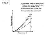
- FIG. 8 is a graph showing a relation between mechanical loss and rotation speed of journal in a journal bearing of oil flooded type.
- the total mechanical loss increases nearly proportional to the square of the rotation speed. It consists of frictional loss X between the journal surface and bearing surfaces of the lower pads on which bearing load exerts, frictional loss Y between the outer circumference of the journal and bearing surfaces of the upper pads on which bearing load does not exerts, and mechanical loss Z which is the sum of the frictional loss due to the side seals and agitation loss of oil in the spaces between the pads due to agitation by the rotation of the journal.
- Direct lubrication type of tilting pad radial bearing was proposed to eliminate the mechanical loss Z.
- oil supply nozzles are provided at the upstream side of each tilting pad upstream in relation to journal rotation direction and lubrication oil is supplied to the bearing surface of each tilting pad, and side seals are eliminated.
- Direct lubrication type is now widely adopted, as mechanical loss Z can be eliminated.
- the tilting pad journal bearing of the patent literature 1 is of direct lubrication type.
- Lubrication oil rises in temperature in the interstice defined by the circumferential surface of the journal and bearing surfaces of the tilting pad (hereunder referred to as bearing clearance of the tilting pad) due to shearing force in the lubrication oil in the interstice caused by the rotation of the journal.
- Lubrication oil increased in temperature in the bearing clearance of the upstream tilting pad is carried over to the bearing clearance of the adjacent downstream tilting pad, so the lubrication oil is further increased in temperature in the bearing clearance of the downstream tilting pad, which may cause overheat of the bearing surface of the tilting pad and bearing seizure.
- a bearing clearance of a tilting pad (clearance between the journal surface and bearing surface of the tilting pad) is filled with lubrication oil, the pad is supported by the stationary bearing housing, and the journal rotates at high speed in the oil filled in the clearance. Therefore, very large speed difference is developed in the oil between the bearing surface of the pad and journal surface.
- a wedge-form oil film is formed between the bearing surface of the pad and journal surface due to the speed difference, and oil pressure is generated in the oil film to support load exerted from the journal onto the bearing surface of the pad.
- FIG.9 is a quotation of FIG.33 of the patent literature 3, showing pressure distribution in the lubrication oil film between the journal surface and bearing surface.
- a plurality of tilting pads 101a ⁇ d are disposed around the journal 100 to support the journal 100.
- Radial clearances 102 between the journal 100 and the tilting pads 101a ⁇ d are filled with lubrication oil. Integration of oil film pressures F p exerting to the bearing faces of the pads coincides with the bearing load W.
- High oil film pressure is generated by the effect of wedge shape of the oil film narrowing the radial clearances 102 downstream of rotation direction of the journal due to tilting the each tilting pads 101a ⁇ d.
- a plurality of bearing housing supporting liners are provided between the bearing housing 05 and bearing platform (including bearing casing 07 and bearing cap 08) to fixedly support the bearing housing to the bearing platform by the intermediary of the spherical liners.
- Each of the spherical liners is provided such that its circumferential position coincides with each of the spherical pivots so that bearing load exerted on each of the tilting pads is supported by the bearing platform by the intermediary of each of the spherical liners between the bearing housing and bearing platform, thereby securing firm supporting of the bearing housing by the bearing platform.
- lubrication oil is supplied from the bearing platform passing through an oil hole drilled in the spherical liner to the oil passage in the bearing housing to be supplied to the bearing surfaces of the tilting pads.
- FIG.6 of the patent literature 1 is shown such an example that a separate load supporting member (spherical liner 06 located at a position vertically under the journal behind the bearing housing) is provided apart from 4 load supporting members 06 and an oil hole is provided in the separate load supporting member. As the oil hole is located at the space between adjacent tilting pads, rigidity of the bearing housing to support the journal decreases.
- an the object of the invention is to provide a oil supply mechanism which enables reliable supply of lubrication oil to the bearing surfaces of tilting pads without leading to decrease in rigidity and increase in size of the journal bearing while retaining facility of assembling the bearing.
- the present invention proposes a journal bearing having a bearing platform, a cylindrical bearing housing supported by the bearing platform by the intermediary of a plurality of load supporting members provided between the bearing platform and the bearing housing, a plurality of pads located inside the bearing housing swingablly so that a journal of a rotation shaft is supported by the pads capable of being self-aligning, and oil supply means for supplying lubrication oil to the bearing surfaces of the pads, wherein a connecting member is provided between the bearing platform and the bearing housing at a position circumferentially apart from one of said load supporting members, said connecting member having an oil hole to communicate an oil supply passage in the bearing platform, which is an upstream oil passage, with an oil supply passage in the bearing housing, which is a downstream oil passage, so that lubrication oil is supplied from the bearing platform to the bearing surfaces of the pads, said connecting member also serving to carry a part of bearing load exerted from the bearing housing, and said connecting member is mounted to said position in such a manner that said part of bearing load carried by the
- a connecting member is provided between the bearing platform and bearing housing at a position circumferentially apart from one of the load supporting members separately in addition to the load supporting members, and the load supporting member is not provided with an oil hole in order to prevent decrease in rigidity thereof, instead the connection member is provided with an oil hole.
- the connecting member is mounted in such a manner that the load that the connecting member receives from the bearing housing is smaller than the load received by the load supporting member for the purpose of reducing the burden share of connecting member to support the bearing load and the number of the load supporting member is not increased, easiness of assembling the journal bearing can be retained.
- the connecting member is located between the bearing platform and lower bearing housing which is loaded with the self weight of the rotation shaft.
- the upper bearing housing is produced as an upper half separate from the lower bearing housing and assembled as a cover member to cover the lower bearing housing, so it is not suited to provide the connecting member thereon. Further, there is a case that the upper bearing platform is not provided.
- the connecting member does not exert on the upper bearing housing, when the connecting member is provided to the upper bearing housing, it is difficult to eliminate occurrence of oil leakage from the oil hole of the connecting member, and furthermore, it is not easy to make adjusting so that the load carried by the connecting member becomes smaller than the load exerted on the bearing platform from the bearing housing by the intermediary of the load supporting member.
- an elastic member such as an O-ring is placed between the connecting member and bearing platform, thereby the connecting member being mounted so that a part of bearing load carried by the connecting member becomes smaller than bearing load carried by one of the load supporting members.
- journal bearing of the invention such that it is of a direct lubrication type in which lubrication oil is supplied to the bearing surfaces of the pads from oil supply nozzles located upstream of each of the pads in relation to rotation direction of the journal, wherein the downstream oil passage comprises a first oil hole communicating to the oil hole of the connecting member and a second oil passage communicating to nozzle holes of the oil supply nozzles.
- the journal bearing having a bearing platform, a cylindrical bearing housing supported by the bearing platform by the intermediary of a plurality of load supporting members, a plurality of pads located swingablly in the bearing housing so that a journal of a rotation shaft is supported by the pads capable of being self-aligning, and oil supply means for supplying lubrication oil to the bearing surfaces of the pads, is composed such that a connecting member is provided at a position apart from one of said load supporting members in the circumferential direction of the bearing housing between the bearing platform and the bearing housing, said connecting member having an oil hole to communicate an oil supply passage which is an upstream oil passage in the bearing platform with an oil supply passage which is a downstream side oil passage in the bearing housing so that lubrication oil is supplied from the bearing platform to the bearing surfaces of the pads, said connecting member also serving to carry a part of bearing load exerted from the bearing housing, and said connecting member is mounted to said position in such a manner that said part of bearing load carried by the connecting member is smaller than bearing load carried by one of the
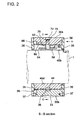
- FIGS. 1 ⁇ 3 show an embodiment of the journal bearing of the invention
- FIG.1 is a sectional front view along line C-C in FIG.2
- FIG.2 is a sectional side view along line B-B in FIG. 3
- FIG. 3 is a rear view viewed in the direction of arrow A in FIG.2 .
- a journal j is that of a rotation shaft of large rotating machine such as a steam turbine, gas turbine, and an electric generator.
- the diameter of the journal j is as large as about 40cm, so the journal bearing 10 to support the journal j becomes large in size, and circumferential velocity of the journal j becomes high.
- the journal j rotates in the direction of arrow a.
- the journal bearing 10 supporting the journal j is comprised of a bearing platform 20, a bearing housing 30 comprising an upper semi-cylindrical housing 30a and a lower semi-cylindrical housing 30b fixedly supported by the bearing platform 20, and four tilting pads 40a ⁇ d attached to the inner circumferential surface of the bearing housing 30.
- a ⁇ d will be omitted when matter common to all of the tilting pads is recited. This is similarly applied to other constituent parts.
- the bearing platform 20 has a concave part 20a semicircular in section, and the bearing housing 30 is cut in two halves of the upper bearing housing 30a and lower bearing housing 30b.
- the lower bearing housing 30b is supported by the semicircular concave part 20a of the bearing platform 20.
- the upper bearing housing 30a is positioned by means of a positioning pin 31 to the lower bearing housing 30b and connected to the lower bearing housing 30b by means of fastening bolts 32 as shown in FIG.3 .
- a recess 42 is provided in the back face (outer face) of each of the tilting pads 40 near the center part thereof, and an adjusting liner 44 is press fit in the recess.
- a recess 34 is formed in the inner face of the bearing housing 30 at a position facing the adjusting liner 44, and a spherical pivot 36 is inserted in the recess.
- the surface of the spherical pivot 36 facing the adjusting liner 44 is formed into a spherical surface so that the tilting pad 40 is circumferentially and axially swingable in relation to the journal j.
- the tilting pads 40 are located such that a circumferential spacing s1 is provided between each of the pads.
- the spherical pivots 36 are located such that their centers are at positions 45° from the vertical center line or horizontal center line of the journal bearing.
- the tilting pad 40 can be removed from the bearing assembly with the adjusting liner 44 fixed in the recess 42 thereof by removing a side plate mentioned later and sliding the tilting pad in the axial direction of the journal.
- Radial holes for measurement 38 are drilled in the upper bearing housing 30a penetrating the upper bearing housing 30a from the outer periphery thereof to the recesses 34.
- An outer liner 33(bearing load supporting medium) is provided on the outer periphery of the bearing housing 30 at a circumferential position thereof radially opposite behind the bearing housing 30 to the spherical pivot 36 located in the recess 34 in the inside face of the bearing housing 30.
- a hole 33a is drilled in the outer liner 33 to communicate with the hole for measurement 38.
- the hole for measurement 38 is plugged by a plug 39 after measurement mentioned later is finished.
- the outer liner 33 is attached to the outer periphery of the bearing housing 30 by means of fastening bolts not shown in the drawings.
- the outer periphery of the outer liner 33 protrudes a little from the circumferential surface of the bearing housing 30.
- the outer liner 33 contacts the concave surface 20a of the bearing platform 20, and the lower bearing housing 30b is supported by the bearing platform 20 via the medium of the outer liner 33.
- annular side plates 35 are attached to both side ends of the bearing housing 30 to retain the tilting pads between the inner circumferential surface of the bearing housing and the rotating surface of the journal j.
- the annular side plates 35 are fixed to both sides of the bearing housing 30 by means of a plurality of fastening bolts 37.
- the oil supply nozzles 50 for injecting lubrication oil are attached to the bearing housing 30 to be located at both end sides of each of the tilting pads 40, that is, located at the upstream side and down stream side in relation to the rotation direction of the journal j.
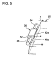
- FIG.5 shows an example of the oil supply nozzle 50 in a perspective view.
- structure of the oil supply nozzle 50 will be explained referring to FIG.2 and FIG.5 .
- the oil supply nozzles located in the upstream side are same in construction as those located in the downstream side.
- the oil supply nozzle 50 consists of a main casing 52 and nozzle arms 54.
- the main casing 52 has a rectangular parallelpiped part and cylindrical part.
- the nozzle arms 54 extend from both side faces opposite to each other of the rectangular parallelpiped part.
- the cylindrical part is inserted into a radial hole 70 drilled at an axial center part of the bearing housing 30 so that the rectangular parallelpiped part is located adjacent to the circumferential side end of the tilting pad 40 and the nozzle arms 54 extend in the axial direction of the journal j.
- the main casing 52 and arms 54 have a hollow 56 into which lubrication oil is introduced.
- Each of the nozzle arms 54 has a plurality of nozzle holes 58 at equal spacing along the arm so that the nozzle holes 58 face toward the journal j along the axial direction thereof when the oil supply nozzle 50 is attached to the bearing housing 30.
- Lubrication oil injected from the nozzle holes 58 of the oil supply nozzle 50 located in the upstream side of the tilting pad 40 in relation to rotation direction of the journal j intrudes into the radial clearance between the inner circumferential surface of the tilting pad 40 (bearing surface 48 in FIG. 4 ) and the rotating surface of the journal j dragged by the rotation of the journal j to form oil film there.
- Lubrication oil injected from the nozzle holes 58 of the oil supply nozzle 50 located in the downstream side of the tilting pad 40 in relation to rotation direction of the journal j cools the lubrication oil passed through the clearance between the bearing surface of the tilting pad and rotating surface of the journal j(oil clearance between the journal and tilting pad) and concurrently disrupts the oil film adhered on the rotating surface of the journal j to make the oil film to be separated therefrom.
- intrusion of lubrication oil dragged by the rotation surface of the journal from the oil clearance between the journal and upstream tilting pad into the oil clearance between the journal and downstream tilting pad next to said upstream tilting pad is prevented.
- Lubrication oil flowed out from the downstream end of the tilting pad is drained through the radial clearance s3 between the side plate 35 and journal j.
- the main casing 52 is attached to the bearing housing such that a face 52a of the rectangular parallelpiped part thereof facing the tilted surface 46 of the tilting pad 40 contacts a base part-46a of the tilted surface 46 of the tilting pad 40, and tilted surface 46 skews by a small angle ⁇ so that the clearance between the tilted surface 46 and the face 52a increases radially inwardly.
- the base part 46a of the tilted surface 46 of the tilting pad 40 is supported at the face 52a of the main casing 52 in a form of line-contact, thereby the oil supply nozzle 50 supports immovably the movement of the tilting pad in the direction of the journal rotation.
- an oil supply hole 60 is provided in the bearing platform 20.
- An outer liner 62 is located on the outer periphery of the lower bearing housing 30b at a position facing the oil supply hole 60. Configuration of this portion will be explained referring to FIG.6 .
- the outer liner 62 has an oil supply hole 62a communicating to the oil supply hole 60.
- An oil supply hole 64 is drilled radially in the lower bearing housing 30b such that the oil supply hole 64 communicates to the oil supply hole 60 by way of the oil supply hole 62a of the outer liner 62.
- Annular oil groove 66 is provided in an axial side face of the bearing housing 30.
- the annular oil groove 66 runs all around the axial side end of the bearing housing 30. As shown in FIG. 2 , the annular oil groove 66 is communicated to the hollow 56 of the main casing 52 of the oil supply nozzle 50 by an axial oil hole 68 in the bearing housing 30. The open end of the hollow 56 at the end of the cylindrical part of the main casing 52 is closed by a plug 72 and the plug 72 is secured by a C-shaped retaining ring 74.
- a radial clearance s4 is formed between the inner circumferential surface of the bearing platform 20 and outer periphery of the outer liner 62 (see FIG. 6 ).
- An o-ring 76 is placed in the clearance s4 to seal the clearance. By this, oil leakage through the clearance s4 is prevented and concurrently the o-ring 76 serves so that a bearing load exerted on the bearing platform 20 from the lower bearing housing 30b by the intermediary of the outer liner 62 becomes smaller than a bearing load exerted on the bearing platform 20 from the lower bearing housing 30b by the intermediary of the outer liner 33.
- two circular recesses 84 are provided in the outer circumferential surface of the tilting pads 40a and 40b at a certain spacing in the axial direction thereof and two circular recesses 82 in the circumferential surface of the upper housing 30a.
- Each of the circular recesses faces each other so that a cylindrical hollow is formed.
- the recesses 84 are provided near the downstream end of the tilting pads 40a and 40b in relation to the rotation direction of the journal j as can be seen in FIG. 1 .
- a coil spring 80 which pushes the tilting pad radially toward the journal j near the downstream side end thereof. Therefore, as shown in FIG.9 , it becomes easy that an oil clearance narrowing in the rotation direction of the journal j is formed between rotating surface of the journal and bearing surface of tilting pad 40a and 40b.
- radial screw holes 90 are provided near the upstream end part and downstream end part of each of the tilting pads 40 in relation to the rotation direction of the journal j.
- Radial through holes 92 are drilled in the bearing housing 30 where the radial though hole 92 faces the opening of the corresponding radial screw hole 90 so that the radial through hole 92 and the radial screw hole 90 has a same axis line.
- a hexagon socket head screw 94 is inserted through each of the radial through holes 92 and its fore-end part is screwed into each of the screw holes 90.
- the radial clearance between the inner surface of the bearing housing 30 and the outer surface of the tilting pad 40 can be adjusted by adjusting screwed-in length of the hexagon socket head screws 94, thereby the radial clearance (bearing clearance) between the rotating surface of the journal and bearing surface of the tilting pad 40 can be adjusted.
- the upstream side radial clearance and downstream side radial clearance between the journal surface and bearing surface of the tilting pad can be adjusted separately, that is, the attitude of the tilting pad can be adjusted, to obtain a wedge-shaped radial clearance by a compact and inexpensive means.
- lubrication oil is supplied from the oil supply hole 60 provided in the bearing platform 20 to the hollows 56 of the oil supply nozzles 50 through the annular oil groove 66 and axial oil hole 68 in the bearing housing 30.
- the lubrication oil is injected from the nozzle holes 58 of the nozzle arms 54 of the oil supply nozzle 50 toward the rotating surface of the journal j.
- Lubrication oil injected from the oil supply nozzle 50 located at the upstream side of the tilting pad 40 in relation to the rotation direction of the journal j is introduced into the oil clearance between the journal and tilting pad to lubricate the rotating surface of the journal j and bearing surface 48.
- excessive temperature rise of the bearing surface 48 of the tilting pad 40 can be prevented and occurrence of bearing seizure is prevented.
- Radial clearance between the journal surface and bearing surface 48 of the tilting pad can be adjusted to a desired clearance by measuring the distance from the rear face of the spherical pivot 36 to the open end of the radial hole for measurement 38 by means of a known measuring device and determine the radial clearance between the journal surface and bearing surface 48, and inserting an adjusting shim 86 in the recess 34 on the back face of the spherical pivot 36 based on the measurement.
- clearance adjusting means together with the clearance adjusting by the hexagon socket head screws 94, clearance between the journal surface and bearing surface of the tilting pad can be adjusted to a desired clearance with high accuracy such that the clearance becomes narrow toward the downstream side of the tilting pad in relation to the rotation direction of the journal as shown in FIG. 9 . Therefore, high oil film pressure owing to the wedge effect can be generated easier on the bearing surface 48 and high performance of lubrication of the bearing surface 48 can be maintained.
- Self weight of the rotation shaft exerts on the tilting pads 40c and 40d located on the lower bearing housing 30b, so a wedge-shaped radial clearance narrowing downstream as shown in FIG.9 can be formed relatively easily.
- the self weight of the rotation shaft does not exerts on the tilting pads 40a and 40b located on the upper housing 30a, so the formation of high pressure oil film between the journal surface and bearing surfaces 48 of the upper tilting pads 40a and 40b can not be expected.
- the downstream end part of each of the tilting pads 40a and 40b located on the upper bearing housing 30a are pushed downward by the elastic force of the coil springs 80, so wedge-shaped radial clearance narrowing downstream can be easily formed also in the upper tilting pads 40a and 40b. Therefore, high pressure oil film can be generated on the bearing surface of the upper tilting pads 40a and 40b by the wedge effect.
- journal bearing can be simplified in structure.
- the space in front and rear side of the tilting pad can be broaden, which enables to realize further stable supply of the lubricating oil.
- the spherical pivot 36 is received in the recess of the bearing housing 30 such that it extends into the recess of the tilting pad 40 so that the spherical pivot 36 serves to prevent circumferential movement of the tilting pad 40.
- Such configuration is not needed according to the embodiment of the present invention. Therefore, by allowing the spherical surface of the spherical pivot to be level with the inner circumferential surface of the bearing housing 30, the tilting pad 40 can be drawn out axially along the journal j by only removing the side plate 35. Therefore, the tilting pad 40 can be removed with the journal in the place as it is, which facilitates removing and attaching of the tilting pad 40 when repairing or changing same.
- the outer liner 62 having the oil supply hole 62a which communicate with the oil supply hole 60 in the bearing platform 20 separately in addition to the outer liners 33, reduction of rigidity of the outer liner 33 if an oil hole is drilled to it as is in a conventional example of tilting pad journal bearing can be eliminated. Therefore, necessity of increasing radial thickness of the bearing housing to compensate for the reduction in rigidity of the outer liner can be eliminated.
- the oil supply hole 62a can be provided without increasing the number of the outer liner 33. Therefore, there is no change in the number of the outer liner 33, so there is no need to raise the dimensional accuracy of the outer liner 33, and easiness of assembling the journal bearing can be retained.
- the bearing load which exerts on the lower bearing housing 30b can be adjusted easily by the outer liner 62, and in addition, as the o-ring 76 capable of elastic deformation is placed between the outer liner 62 and bearing platform 20, said adjustment of the bearing load is further facilitated.
- lubrication oil is supplied to the nozzles arms 54 of the oil supply nozzles 50 through the oil supply hole 60 in the bearing platform 20, annular oil groove 66, oil supply hole 68, and the hollow 56 in the main casing of the oil supply nozzle 50 with simple construction without decreasing the rigidity of the bearing housing 30.
- the O-ring is used between the outer liner 62 and bearing platform 20 in the embodiment, however, other elastic member, for example, a bellow and so on may be used instead of the O-ring.
- other elastic member for example, a bellow and so on may be used instead of the O-ring.
- a tilting pad type journal bearing provided with a means for supplying lubrication oil to the bearing surfaces of the tilting pads
- a means for supplying lubrication oil to the bearing surfaces of the tilting pads can be provided which can be constructed without leading to decrease in rigidity and increase in size of the journal bearing, in which lubrication oil can be supplied to the bearing surfaces of the pads with certainty, and which can be preferably adopted in large size rotating machines such as steam turbines, gas turbines, and electric generators.
Description
- The present invention relates to a journal bearing of pad type for supporting a journal of a rotation shaft of rotating machines, and can be preferably applied to large size rotating machines such as steam turbines, gas turbines, and electric generators.
- A self-aligning journal bearing having tiling pads has been used as a journal bearing of a large size rotating machine.
- A journal bearing having tilting pads devised by the applicant of this application is disclosed in patent literature 1(Japanese Laid-Open Patent Application No.
5-332355 patent literature 1, each of the tilting pads is supported by means of a spherical pivot and an adjusting liner received in a recess defined in the back side face of the tilting pad and in a recess defined in the inner side face of the bearing housing such that the pad is swingable about an axis parallel with the rotation shaft (circumferentially swingable) and about a direction perpendicular to the axial direction of the rotation shaft (axially swingable). - As the pads are swingable circumferentially and axially in accordance with the movement of the journal, a journal bearing of tilting pad type has self-aligning function.
- Therefore, it can support a journal stably and is preferably adopted for high speed rotating machines.
- The spherical pivot is received in both the recess in the tilting pad and the recess in the bearing housing so that it serves as a stopper of the tilting pad, i.e. the tilting pad is prevented from being dragged circumferentially by the rotation of the journal.
- In a tilting pad journal bearing disclosed in patent literature 2(Japanese Patent Publication No.
10-503827 socket 42 and locating means 24 comprising aspigot member 40 and platform body 23 is adopted to inhibit displacement of the pad in a circumferential direction when the shaft is in motion. - There are two types of tilting pad journal bearing, i.e., oil flooded lubrication type and direct lubrication type. In the oil flooded lubrication type, both axial end sides of the tilting pad are sealed so that spaces between a tilting pad and the adjacent tilting pad are flooded with lubrication oil. With this type, mechanical efficiency decreases due to friction loss of the side seals and agitation loss of oil in the spaces between the tilting pads.
- Occurrence of decrease of mechanical efficiency will be explained referring to
FIG.8 quoted from thepatent literature 1.FIG. 8 is a graph showing a relation between mechanical loss and rotation speed of journal in a journal bearing of oil flooded type. In the graph, the total mechanical loss increases nearly proportional to the square of the rotation speed. It consists of frictional loss X between the journal surface and bearing surfaces of the lower pads on which bearing load exerts, frictional loss Y between the outer circumference of the journal and bearing surfaces of the upper pads on which bearing load does not exerts, and mechanical loss Z which is the sum of the frictional loss due to the side seals and agitation loss of oil in the spaces between the pads due to agitation by the rotation of the journal. - Direct lubrication type of tilting pad radial bearing was proposed to eliminate the mechanical loss Z. In the direct lubrication type, oil supply nozzles are provided at the upstream side of each tilting pad upstream in relation to journal rotation direction and lubrication oil is supplied to the bearing surface of each tilting pad, and side seals are eliminated. Direct lubrication type is now widely adopted, as mechanical loss Z can be eliminated. The tilting pad journal bearing of the
patent literature 1 is of direct lubrication type. - Another type of direct lubrication type tilting pad radial bearing is proposed in patent liter, 3(Japanese Laid-Open Patent Application No.
2000-274432 patent literature 3. This is a phenomenon that the lubrication oil lubricated the bearing surface of an upstream tilting pad is carried on the rotating journal to be introduced to the bearing surface of the adjacent downstream tilting pad. - Lubrication oil rises in temperature in the interstice defined by the circumferential surface of the journal and bearing surfaces of the tilting pad (hereunder referred to as bearing clearance of the tilting pad) due to shearing force in the lubrication oil in the interstice caused by the rotation of the journal. Lubrication oil increased in temperature in the bearing clearance of the upstream tilting pad is carried over to the bearing clearance of the adjacent downstream tilting pad, so the lubrication oil is further increased in temperature in the bearing clearance of the downstream tilting pad, which may cause overheat of the bearing surface of the tilting pad and bearing seizure.
- Means of preventing carryover of lubrication oil in a direct lubricating type tilting pad journal bearing are proposed in the
patent literature 3. - In patent literature 4(Japanese Laid-Open Patent Application No.
2006-112499 - As recited in paragraph [0004] of the
patent literature 3, a bearing clearance of a tilting pad (clearance between the journal surface and bearing surface of the tilting pad) is filled with lubrication oil, the pad is supported by the stationary bearing housing, and the journal rotates at high speed in the oil filled in the clearance. Therefore, very large speed difference is developed in the oil between the bearing surface of the pad and journal surface. A wedge-form oil film is formed between the bearing surface of the pad and journal surface due to the speed difference, and oil pressure is generated in the oil film to support load exerted from the journal onto the bearing surface of the pad. -
FIG.9 is a quotation of FIG.33 of thepatent literature 3, showing pressure distribution in the lubrication oil film between the journal surface and bearing surface. In the drawing, a plurality of tiltingpads 101a∼d are disposed around thejournal 100 to support thejournal 100.Radial clearances 102 between thejournal 100 and the tiltingpads 101a∼d are filled with lubrication oil. Integration of oil film pressures Fp exerting to the bearing faces of the pads coincides with the bearing load W. - High oil film pressure is generated by the effect of wedge shape of the oil film narrowing the
radial clearances 102 downstream of rotation direction of the journal due to tilting the eachtilting pads 101a∼d. - As shown in
FIG. 1 ,3 , and6 of thepatent literature 1, a plurality of bearing housing supporting liners (spherical liners 06) are provided between the bearing housing 05 and bearing platform (including bearing casing 07 and bearing cap 08) to fixedly support the bearing housing to the bearing platform by the intermediary of the spherical liners. Each of the spherical liners is provided such that its circumferential position coincides with each of the spherical pivots so that bearing load exerted on each of the tilting pads is supported by the bearing platform by the intermediary of each of the spherical liners between the bearing housing and bearing platform, thereby securing firm supporting of the bearing housing by the bearing platform. - On the other hand, lubrication oil is supplied from the bearing platform passing through an oil hole drilled in the spherical liner to the oil passage in the bearing housing to be supplied to the bearing surfaces of the tilting pads.
- However, when the bearing load supporting member is provided with an oil hole to introduce lubrication oil, rigidity of the load supporting member decreases, and as a tilting pad supporting member is located at radially inwardly opposite position behind the bearing housing as can be seen in the
patent literatures - In
FIG.6 of thepatent literature 1 is shown such an example that a separate load supporting member (spherical liner 06 located at a position vertically under the journal behind the bearing housing) is provided apart from 4 load supporting members 06 and an oil hole is provided in the separate load supporting member. As the oil hole is located at the space between adjacent tilting pads, rigidity of the bearing housing to support the journal decreases. - Generally, four load supporting members are located along the circumference of the bearing housing at equal spacing, however, when five load supporting members are provided as in the case of
FIG.6 of thepatent literature 1, high accuracy in assembling is necessary to effect equal load sharing for the five load supporting members. - Patent literature 1: Japanese laid-open Patent Application No,
5-332355 - Patent literature 2: Japanese Patent publication No.
10-503827 - Patent literature 3: Japanese laid-open Patent Application No.
2000-274432 - Patent literature 4: Japanese laid-open Patent Application No.
2006-112499 - The present invention was made in light of problems of the prior art mentioned above, an the object of the invention is to provide a oil supply mechanism which enables reliable supply of lubrication oil to the bearing surfaces of tilting pads without leading to decrease in rigidity and increase in size of the journal bearing while retaining facility of assembling the bearing.
- To attain the object mentioned above, the present invention proposes a journal bearing having a bearing platform, a cylindrical bearing housing supported by the bearing platform by the intermediary of a plurality of load supporting members provided between the bearing platform and the bearing housing, a plurality of pads located inside the bearing housing swingablly so that a journal of a rotation shaft is supported by the pads capable of being self-aligning, and oil supply means for supplying lubrication oil to the bearing surfaces of the pads, wherein a connecting member is provided between the bearing platform and the bearing housing at a position circumferentially apart from one of said load supporting members, said connecting member having an oil hole to communicate an oil supply passage in the bearing platform, which is an upstream oil passage, with an oil supply passage in the bearing housing, which is a downstream oil passage, so that lubrication oil is supplied from the bearing platform to the bearing surfaces of the pads, said connecting member also serving to carry a part of bearing load exerted from the bearing housing, and said connecting member is mounted to said position in such a manner that said part of bearing load carried by the connecting member is smaller than a bearing load carried by one of the load supporting members.
- In the invention, a connecting member is provided between the bearing platform and bearing housing at a position circumferentially apart from one of the load supporting members separately in addition to the load supporting members, and the load supporting member is not provided with an oil hole in order to prevent decrease in rigidity thereof, instead the connection member is provided with an oil hole. As a result, increase of radial thickness of the bearing housing to compensate for the reduction in rigidity of the load supporting member becomes unnecessary.
- Further, as the connecting member is mounted in such a manner that the load that the connecting member receives from the bearing housing is smaller than the load received by the load supporting member for the purpose of reducing the burden share of connecting member to support the bearing load and the number of the load supporting member is not increased, easiness of assembling the journal bearing can be retained.
- In the journal bearing of the invention, it is preferable that the connecting member is located between the bearing platform and lower bearing housing which is loaded with the self weight of the rotation shaft. There is a case that the upper bearing housing is produced as an upper half separate from the lower bearing housing and assembled as a cover member to cover the lower bearing housing, so it is not suited to provide the connecting member thereon. Further, there is a case that the upper bearing platform is not provided.
- Further, as the self weight of the rotation shaft does not exert on the upper bearing housing, when the connecting member is provided to the upper bearing housing, it is difficult to eliminate occurrence of oil leakage from the oil hole of the connecting member, and furthermore, it is not easy to make adjusting so that the load carried by the connecting member becomes smaller than the load exerted on the bearing platform from the bearing housing by the intermediary of the load supporting member.
- On the other hand, as the self weight of the rotation shaft is exerted on the lower bearing housing, it is easy to make adjustment so that the load carried by the connecting member becomes smaller than the load carried by the load supporting member to be exerted on the bearing platform when the connecting member is provided to the lower bearing housing. Therefore, it is easier for assembling to locate the connecting member between the lower bearing housing and bearing platform.
- It is preferable that an elastic member such as an O-ring is placed between the connecting member and bearing platform, thereby the connecting member being mounted so that a part of bearing load carried by the connecting member becomes smaller than bearing load carried by one of the load supporting members.
- By mounting the connecting member between the lower bearing housing and bearing platform by the intermediary of an elastic member such as an O-ring, it becomes easier to adjust the load carried by the connecting member to support the bearing housing, and also assembling of the journal bearing is facilitated.
- It is preferable to compose the journal bearing of the invention such that it is of a direct lubrication type in which lubrication oil is supplied to the bearing surfaces of the pads from oil supply nozzles located upstream of each of the pads in relation to rotation direction of the journal, wherein the downstream oil passage comprises a first oil hole communicating to the oil hole of the connecting member and a second oil passage communicating to nozzle holes of the oil supply nozzles.
- With this construction, lubrication oil introduced from the bearing platform into the bearing housing through the oil hole drilled in the connecting member is supplied to the oil supply nozzles through the first oil passage and second oil passage in the bearing housing without decreasing rigidity of the bearing housing and with simple construction.
- According to the invention, the journal bearing having a bearing platform, a cylindrical bearing housing supported by the bearing platform by the intermediary of a plurality of load supporting members, a plurality of pads located swingablly in the bearing housing so that a journal of a rotation shaft is supported by the pads capable of being self-aligning, and oil supply means for supplying lubrication oil to the bearing surfaces of the pads, is composed such that a connecting member is provided at a position apart from one of said load supporting members in the circumferential direction of the bearing housing between the bearing platform and the bearing housing, said connecting member having an oil hole to communicate an oil supply passage which is an upstream oil passage in the bearing platform with an oil supply passage which is a downstream side oil passage in the bearing housing so that lubrication oil is supplied from the bearing platform to the bearing surfaces of the pads, said connecting member also serving to carry a part of bearing load exerted from the bearing housing, and said connecting member is mounted to said position in such a manner that said part of bearing load carried by the connecting member is smaller than bearing load carried by one of the load supporting members. With this construction, lubrication oil is supplied to the bearing surfaces of the pads without decreasing bearing load supporting rigidity of the bearing housing, as a result, it becomes unnecessary to increase the radial thickness of the bearing housing, and also it is unnecessary to increase the number of the load supporting members located between the bearing platform and bearing housing, and easiness of assembling the journal bearing is retained.
-
-
FIG.1 is a sectional front view of embodiment of the journal bearing of the present invention (C-C section inFIG.2 ). -
FIG. 2 is a sectional side view of the embodiment ofFIG. 1 (B-B section inFIG.3 ). -
FIG.3 is a rear view of the embodiment ofFIG.1 (view in the direction of arrow A inFIG.2 ). -
FIG.4 is a partial enlarged sectional view near thespherical pivot 36 inFIG. 1 . -
FIG.5 is a perspective view of theoil supply nozzle 50 of the embodiment ofFIG. 1 . -
FIG.6 is a partial enlarged sectional view near theoil supply hole 60 inFIG. 1 . -
FIG.7 is a sectional view along line D-D inFIG.1 . -
FIG.8 is a graph showing mechanical loss in a tilting pad journal bearing of oil flooded type. -
FIG.9 is a drawing for explaining of formation of oil film pressure in the journal bearing due to wedge effect. - A preferred embodiment of the present invention will now be detailed with reference to the accompanying drawings. It is intended, however, that unless particularly specified, dimensions, materials, relative positions and so forth of the constituent parts in the embodiments shall be interpreted as illustrative only not as limitative of the scope of the present invention.
-
FIGS. 1∼3 show an embodiment of the journal bearing of the invention,FIG.1 is a sectional front view along line C-C inFIG.2, FIG.2 is a sectional side view along line B-B inFIG. 3, and FIG. 3 is a rear view viewed in the direction of arrow A inFIG.2 . - In
FIG. 1 , a journal j is that of a rotation shaft of large rotating machine such as a steam turbine, gas turbine, and an electric generator. The diameter of the journal j is as large as about 40cm, so the journal bearing 10 to support the journal j becomes large in size, and circumferential velocity of the journal j becomes high. The journal j rotates in the direction of arrow a. - The journal bearing 10 supporting the journal j is comprised of a
bearing platform 20, a bearinghousing 30 comprising an uppersemi-cylindrical housing 30a and a lowersemi-cylindrical housing 30b fixedly supported by the bearingplatform 20, and fourtilting pads 40a∼d attached to the inner circumferential surface of the bearinghousing 30. Hereunder, suffixes a∼d will be omitted when matter common to all of the tilting pads is recited. This is similarly applied to other constituent parts. - The bearing
platform 20 has aconcave part 20a semicircular in section, and the bearinghousing 30 is cut in two halves of theupper bearing housing 30a andlower bearing housing 30b. Thelower bearing housing 30b is supported by the semicircularconcave part 20a of the bearingplatform 20. Theupper bearing housing 30a is positioned by means of apositioning pin 31 to thelower bearing housing 30b and connected to thelower bearing housing 30b by means of fasteningbolts 32 as shown inFIG.3 . - As shown in
FIG. 4 , arecess 42 is provided in the back face (outer face) of each of thetilting pads 40 near the center part thereof, and anadjusting liner 44 is press fit in the recess. Arecess 34 is formed in the inner face of the bearinghousing 30 at a position facing the adjustingliner 44, and aspherical pivot 36 is inserted in the recess. - The surface of the
spherical pivot 36 facing the adjustingliner 44 is formed into a spherical surface so that thetilting pad 40 is circumferentially and axially swingable in relation to the journal j. - As shown in
FIG. 1 , thetilting pads 40 are located such that a circumferential spacing s1 is provided between each of the pads. The spherical pivots 36 are located such that their centers are at positions 45° from the vertical center line or horizontal center line of the journal bearing. - As shown in
FIG.4 , thespherical pivot 36 is received in therecess 34 such that the top of its spherical surface is level with the inner circumferential surface of the bearinghousing 30. Therefore, thetilting pad 40 can be removed from the bearing assembly with the adjustingliner 44 fixed in therecess 42 thereof by removing a side plate mentioned later and sliding the tilting pad in the axial direction of the journal. - Radial holes for
measurement 38 are drilled in theupper bearing housing 30a penetrating theupper bearing housing 30a from the outer periphery thereof to therecesses 34. An outer liner 33(bearing load supporting medium) is provided on the outer periphery of the bearinghousing 30 at a circumferential position thereof radially opposite behind the bearinghousing 30 to thespherical pivot 36 located in therecess 34 in the inside face of the bearinghousing 30. Ahole 33a is drilled in theouter liner 33 to communicate with the hole formeasurement 38. The hole formeasurement 38 is plugged by aplug 39 after measurement mentioned later is finished. - The
outer liner 33 is attached to the outer periphery of the bearinghousing 30 by means of fastening bolts not shown in the drawings. The outer periphery of theouter liner 33 protrudes a little from the circumferential surface of the bearinghousing 30. - Therefore, the
outer liner 33 contacts theconcave surface 20a of the bearingplatform 20, and thelower bearing housing 30b is supported by the bearingplatform 20 via the medium of theouter liner 33. There is a radial clearance s2 between theconcave surface 20a of the bearingplatform 20 and the outer surface of thelower bearing housing 30b. - As shown in
FIG. 2 ,annular side plates 35 are attached to both side ends of the bearinghousing 30 to retain the tilting pads between the inner circumferential surface of the bearing housing and the rotating surface of the journal j. As shown inFIG. 3 , theannular side plates 35 are fixed to both sides of the bearinghousing 30 by means of a plurality offastening bolts 37. There is a radial clearance s3 between the inner periphery of the annular side plate and the rotating surface of the journal j. Lubrication oil injected fromoil supply nozzles 50 is drained through the radial clearance s3 after the lubrication oil served to lubricate between the journal j andpads 40. - As shown in
FIG.1 , theoil supply nozzles 50 for injecting lubrication oil are attached to the bearinghousing 30 to be located at both end sides of each of thetilting pads 40, that is, located at the upstream side and down stream side in relation to the rotation direction of the journal j.FIG.5 shows an example of theoil supply nozzle 50 in a perspective view. Hereunder, structure of theoil supply nozzle 50 will be explained referring toFIG.2 andFIG.5 . The oil supply nozzles located in the upstream side are same in construction as those located in the downstream side. - The
oil supply nozzle 50 consists of amain casing 52 andnozzle arms 54. Themain casing 52 has a rectangular parallelpiped part and cylindrical part. Thenozzle arms 54 extend from both side faces opposite to each other of the rectangular parallelpiped part. The cylindrical part is inserted into aradial hole 70 drilled at an axial center part of the bearinghousing 30 so that the rectangular parallelpiped part is located adjacent to the circumferential side end of thetilting pad 40 and thenozzle arms 54 extend in the axial direction of the journal j. Themain casing 52 andarms 54 have a hollow 56 into which lubrication oil is introduced. - Each of the
nozzle arms 54 has a plurality of nozzle holes 58 at equal spacing along the arm so that the nozzle holes 58 face toward the journal j along the axial direction thereof when theoil supply nozzle 50 is attached to the bearinghousing 30. Lubrication oil injected from the nozzle holes 58 of theoil supply nozzle 50 located in the upstream side of thetilting pad 40 in relation to rotation direction of the journal j intrudes into the radial clearance between the inner circumferential surface of the tilting pad 40 (bearingsurface 48 inFIG. 4 ) and the rotating surface of the journal j dragged by the rotation of the journal j to form oil film there. - Lubrication oil injected from the nozzle holes 58 of the
oil supply nozzle 50 located in the downstream side of thetilting pad 40 in relation to rotation direction of the journal j cools the lubrication oil passed through the clearance between the bearing surface of the tilting pad and rotating surface of the journal j(oil clearance between the journal and tilting pad) and concurrently disrupts the oil film adhered on the rotating surface of the journal j to make the oil film to be separated therefrom. By this, intrusion of lubrication oil dragged by the rotation surface of the journal from the oil clearance between the journal and upstream tilting pad into the oil clearance between the journal and downstream tilting pad next to said upstream tilting pad is prevented. Lubrication oil flowed out from the downstream end of the tilting pad is drained through the radial clearance s3 between theside plate 35 and journal j. - As shown in
FIG.5 , themain casing 52 is attached to the bearing housing such that aface 52a of the rectangular parallelpiped part thereof facing the tiltedsurface 46 of thetilting pad 40 contacts a base part-46a of the tiltedsurface 46 of thetilting pad 40, and tiltedsurface 46 skews by a small angle α so that the clearance between the tiltedsurface 46 and theface 52a increases radially inwardly. In this way, thebase part 46a of the tiltedsurface 46 of thetilting pad 40 is supported at theface 52a of themain casing 52 in a form of line-contact, thereby theoil supply nozzle 50 supports immovably the movement of the tilting pad in the direction of the journal rotation. - As shown in F1G. 1 , an
oil supply hole 60 is provided in thebearing platform 20. Anouter liner 62 is located on the outer periphery of thelower bearing housing 30b at a position facing theoil supply hole 60. Configuration of this portion will be explained referring toFIG.6 . InFIG.6 , theouter liner 62 has anoil supply hole 62a communicating to theoil supply hole 60. - An
oil supply hole 64 is drilled radially in thelower bearing housing 30b such that theoil supply hole 64 communicates to theoil supply hole 60 by way of theoil supply hole 62a of theouter liner 62.Annular oil groove 66 is provided in an axial side face of the bearinghousing 30. - The
annular oil groove 66 runs all around the axial side end of the bearinghousing 30. As shown inFIG. 2 , theannular oil groove 66 is communicated to the hollow 56 of themain casing 52 of theoil supply nozzle 50 by anaxial oil hole 68 in the bearinghousing 30. The open end of the hollow 56 at the end of the cylindrical part of themain casing 52 is closed by aplug 72 and theplug 72 is secured by a C-shapedretaining ring 74. - A radial clearance s4 is formed between the inner circumferential surface of the bearing
platform 20 and outer periphery of the outer liner 62 (seeFIG. 6 ). An o-ring 76 is placed in the clearance s4 to seal the clearance. By this, oil leakage through the clearance s4 is prevented and concurrently the o-ring 76 serves so that a bearing load exerted on thebearing platform 20 from thelower bearing housing 30b by the intermediary of theouter liner 62 becomes smaller than a bearing load exerted on thebearing platform 20 from thelower bearing housing 30b by the intermediary of theouter liner 33. - As shown in
FIG.7 , twocircular recesses 84 are provided in the outer circumferential surface of thetilting pads circular recesses 82 in the circumferential surface of theupper housing 30a. Each of the circular recesses faces each other so that a cylindrical hollow is formed. Therecesses 84 are provided near the downstream end of thetilting pads FIG. 1 . In the cylindrical hollow formed by the two recesses facing each other is installed acoil spring 80, which pushes the tilting pad radially toward the journal j near the downstream side end thereof. Therefore, as shown inFIG.9 , it becomes easy that an oil clearance narrowing in the rotation direction of the journal j is formed between rotating surface of the journal and bearing surface of tiltingpad - As shown in
FIG.1 , radial screw holes 90 are provided near the upstream end part and downstream end part of each of thetilting pads 40 in relation to the rotation direction of the journal j. Radial throughholes 92 are drilled in the bearinghousing 30 where the radial thoughhole 92 faces the opening of the correspondingradial screw hole 90 so that the radial throughhole 92 and theradial screw hole 90 has a same axis line. A hexagonsocket head screw 94 is inserted through each of the radial throughholes 92 and its fore-end part is screwed into each of the screw holes 90. - The radial clearance between the inner surface of the bearing
housing 30 and the outer surface of thetilting pad 40 can be adjusted by adjusting screwed-in length of the hexagon socket head screws 94, thereby the radial clearance (bearing clearance) between the rotating surface of the journal and bearing surface of thetilting pad 40 can be adjusted. - In this manner, the upstream side radial clearance and downstream side radial clearance between the journal surface and bearing surface of the tilting pad can be adjusted separately, that is, the attitude of the tilting pad can be adjusted, to obtain a wedge-shaped radial clearance by a compact and inexpensive means.
- In such an embodiment of the invention, lubrication oil is supplied from the
oil supply hole 60 provided in thebearing platform 20 to thehollows 56 of theoil supply nozzles 50 through theannular oil groove 66 andaxial oil hole 68 in the bearinghousing 30. The lubrication oil is injected from the nozzle holes 58 of thenozzle arms 54 of theoil supply nozzle 50 toward the rotating surface of the journal j. - Lubrication oil injected from the
oil supply nozzle 50 located at the upstream side of thetilting pad 40 in relation to the rotation direction of the journal j is introduced into the oil clearance between the journal and tilting pad to lubricate the rotating surface of the journal j and bearingsurface 48. Lubrication oil injected from theoil supply nozzle 50 located at the downstream side of thetilting pad 40 in relation to the rotation direction of the journal j impinges against the rotating surface of the journal j, cools the lubrication oil risen in temperature in the oil clearance between the journal surface and bearing surface of the upstream tilting pad adhering on the rotating surface of the journal j, and disturbs the oil layer adhering on the rotating surface of the journal to prevent the high temperature oil layer adhered on the rotating surface of the journal from being carried into the oil clearance between the journal surface and bearing surface of the adjacent downstream tilting pad. By this, excessive temperature rise of the bearingsurface 48 of thetilting pad 40 can be prevented and occurrence of bearing seizure is prevented. - Radial clearance between the journal surface and bearing
surface 48 of the tilting pad can be adjusted to a desired clearance by measuring the distance from the rear face of thespherical pivot 36 to the open end of the radial hole formeasurement 38 by means of a known measuring device and determine the radial clearance between the journal surface and bearingsurface 48, and inserting an adjustingshim 86 in therecess 34 on the back face of thespherical pivot 36 based on the measurement. - By using this clearance adjusting means together with the clearance adjusting by the hexagon socket head screws 94, clearance between the journal surface and bearing surface of the tilting pad can be adjusted to a desired clearance with high accuracy such that the clearance becomes narrow toward the downstream side of the tilting pad in relation to the rotation direction of the journal as shown in
FIG. 9 . Therefore, high oil film pressure owing to the wedge effect can be generated easier on the bearingsurface 48 and high performance of lubrication of the bearingsurface 48 can be maintained. - Self weight of the rotation shaft exerts on the
tilting pads lower bearing housing 30b, so a wedge-shaped radial clearance narrowing downstream as shown inFIG.9 can be formed relatively easily. On the other hand, the self weight of the rotation shaft does not exerts on thetilting pads upper housing 30a, so the formation of high pressure oil film between the journal surface and bearingsurfaces 48 of theupper tilting pads - According to the embodiment, the downstream end part of each of the
tilting pads upper bearing housing 30a are pushed downward by the elastic force of the coil springs 80, so wedge-shaped radial clearance narrowing downstream can be easily formed also in theupper tilting pads upper tilting pads - As the self weight of the rotation shaft does not exert on the
upper tilting pads - Further, as the
oil supply nozzles 50 are located at the upstream and downstream side of the tilting pad such that the tilting pad is stopped its movement in the circumferential direction by themain casing 52 of theoil supply nozzle 50, separate means for preventing movement of the tilting pad in the circumferential direction dragged by the rotation of the journal is not needed, and the journal bearing can be simplified in structure. - Further, as the
tilting pad 40 is supported at the outerside periphery part 46a, the space in front and rear side of the tilting pad can be broaden, which enables to realize further stable supply of the lubricating oil. - Conventionally, the
spherical pivot 36 is received in the recess of the bearinghousing 30 such that it extends into the recess of thetilting pad 40 so that thespherical pivot 36 serves to prevent circumferential movement of thetilting pad 40. Such configuration is not needed according to the embodiment of the present invention. Therefore, by allowing the spherical surface of the spherical pivot to be level with the inner circumferential surface of the bearinghousing 30, thetilting pad 40 can be drawn out axially along the journal j by only removing theside plate 35. Therefore, thetilting pad 40 can be removed with the journal in the place as it is, which facilitates removing and attaching of thetilting pad 40 when repairing or changing same. - Furthermore, according to the embodiment, by providing the
outer liner 62 having theoil supply hole 62a which communicate with theoil supply hole 60 in thebearing platform 20 separately in addition to theouter liners 33, reduction of rigidity of theouter liner 33 if an oil hole is drilled to it as is in a conventional example of tilting pad journal bearing can be eliminated. Therefore, necessity of increasing radial thickness of the bearing housing to compensate for the reduction in rigidity of the outer liner can be eliminated. - Further, as the
outer liner 62 is provided such that the load that theouter liner 62 receives from the bearinghousing 30 is smaller than the load received by theouter liner 33, theoil supply hole 62a can be provided without increasing the number of theouter liner 33. Therefore, there is no change in the number of theouter liner 33, so there is no need to raise the dimensional accuracy of theouter liner 33, and easiness of assembling the journal bearing can be retained. - Further, as the
outer liner 62 is provided to thelower bearing housing 30b on which the bearing load exerts from the journal j through the intermediary of thetilting pad 40, the bearing load which exerts on thelower bearing housing 30b can be adjusted easily by theouter liner 62, and in addition, as the o-ring 76 capable of elastic deformation is placed between theouter liner 62 andbearing platform 20, said adjustment of the bearing load is further facilitated. - Further, lubrication oil is supplied to the
nozzles arms 54 of theoil supply nozzles 50 through theoil supply hole 60 in thebearing platform 20,annular oil groove 66,oil supply hole 68, and the hollow 56 in the main casing of theoil supply nozzle 50 with simple construction without decreasing the rigidity of the bearinghousing 30. - The O-ring is used between the
outer liner 62 andbearing platform 20 in the embodiment, however, other elastic member, for example, a bellow and so on may be used instead of the O-ring. By using an elastic member between theouter liner 62 and bearing platform like this, adjustment of the bearing load exerting on thebearing platform 20 from the bearinghousing 30 through theouter liner 62 becomes easy. - According to the invention, a tilting pad type journal bearing provided with a means for supplying lubrication oil to the bearing surfaces of the tilting pads can be provided which can be constructed without leading to decrease in rigidity and increase in size of the journal bearing, in which lubrication oil can be supplied to the bearing surfaces of the pads with certainty, and which can be preferably adopted in large size rotating machines such as steam turbines, gas turbines, and electric generators.
Claims (4)
- A journal bearing (10) having a bearing platform (20), a cylindrical bearing housing (30) supported by the bearing platform (20) by the intermediary of a plurality of load supporting members (33) provided between the bearing platform (20) and the bearing housing (30), a plurality of pads (40) located inside the bearing housing (30) swingablly so that a journal (j) of a rotating shaft is supported by the pads (40) capable of being self-aligning, and oil supply means for supplying lubrication oil to the bearing surfaces (48) of the pads (40), wherein
a connecting member (62) is provided between the bearing platform (20) and the bearing housing (30) at a position circumferentially apart from one of said load supporting members (33), said connecting member (62) having an oil hole (62a) to communicate an oil supply passage (60) in the bearing platform (20), which is an upstream oil passage, with an oil supply passage (64, 66, 68, 50) in the bearing housing (30), which is a downstream oil passage, so that lubrication oil is supplied from the bearing platform (20) to the bearing surfaces (48) of the pads (40), said connecting member (62) also serving to carry a part of bearing load exerted from the bearing housing (30), and said connecting member (62) is mounted to said position in such a manner that said part of bearing load carried by the connecting member (62) is smaller than a bearing load carried by one of the load supporting members (33). - A journal bearing (10) according to claim 1,
wherein the bearing housing (30) has an upper bearing housing (30a) and a lower bearing housing (30b) and said connecting member (62) is located between the bearing platform (20) and the lower bearing housing (30b) which is loaded with the own weight of the rotating shaft. - A journal bearing (10) according to claim 2,
wherein an elastic member such as an O-ring (76) is placed between said connecting member (62) and bearing platform (20), thereby said connecting member (62) being mounted so that a part of bearing load carried by the connecting member (62) is smaller than bearing load carried by one of the load supporting members (33). - A journal bearing (10) according to any one of claims 1 to 3, wherein the journal bearing (10) is of a direct lubrication type in which lubrication oil is supplied to the bearing surfaces (48) of the pads (40) from oil supply nozzles (50) located upstream of each of the pads (40) in relation to rotation direction of the journal (j), wherein said downstream oil passage comprises a first oil hole (64) communicating to the oil hole (62a) of the connecting member (62) and a second oil passage (66) communicating to nozzle holes (58) of the oil supply nozzles (50).
Applications Claiming Priority (2)
| Application Number | Priority Date | Filing Date | Title |
|---|---|---|---|
| JP2008289580A JP4727708B2 (en) | 2008-11-12 | 2008-11-12 | Journal bearing |
| PCT/JP2009/069188 WO2010055847A1 (en) | 2008-11-12 | 2009-11-11 | Journal bearing |
Publications (3)
| Publication Number | Publication Date |
|---|---|
| EP2345819A1 EP2345819A1 (en) | 2011-07-20 |
| EP2345819A4 EP2345819A4 (en) | 2013-03-27 |
| EP2345819B1 true EP2345819B1 (en) | 2014-06-04 |
Family
ID=42169981
Family Applications (1)
| Application Number | Title | Priority Date | Filing Date |
|---|---|---|---|
| EP09826094.6A Active EP2345819B1 (en) | 2008-11-12 | 2009-11-11 | Journal bearing |
Country Status (5)
| Country | Link |
|---|---|
| US (1) | US8371756B2 (en) |
| EP (1) | EP2345819B1 (en) |
| JP (1) | JP4727708B2 (en) |
| CN (1) | CN101981333B (en) |
| WO (1) | WO2010055847A1 (en) |
Families Citing this family (20)
| Publication number | Priority date | Publication date | Assignee | Title |
|---|---|---|---|---|
| US8834032B2 (en) * | 2011-02-21 | 2014-09-16 | Hitachi, Ltd. | Tilting pad journal bearing and rotating machine provided with the same |
| US8545103B1 (en) | 2011-04-19 | 2013-10-01 | Us Synthetic Corporation | Tilting pad bearing assemblies and apparatuses, and motor assemblies using the same |
| CN102619876A (en) * | 2012-03-26 | 2012-08-01 | 哈尔滨汽轮机厂有限责任公司 | Tilting pad bearing with groove on upper bush and spring on bush back |
| JP6412098B2 (en) * | 2013-03-13 | 2018-10-24 | ワウケシャ ベアリングズ コーポレーションWaukesha Bearings Corporation | Trailing edge cooling bearing |
| JP2015007463A (en) * | 2013-06-26 | 2015-01-15 | 三菱日立パワーシステムズ株式会社 | Tilting pad bearing |
| CN103343773B (en) * | 2013-07-10 | 2016-05-04 | 中国电建集团上海能源装备有限公司 | The sliding bearing that a kind of bearing shell is floating type |
| JP5936725B1 (en) * | 2015-01-30 | 2016-06-22 | 三菱日立パワーシステムズ株式会社 | Journal bearing device and rotating machine |
| JP6403594B2 (en) * | 2015-02-06 | 2018-10-10 | 三菱日立パワーシステムズ株式会社 | Journal bearing and rotating machine |
| CN105134800A (en) * | 2015-08-11 | 2015-12-09 | 哈尔滨汽轮机厂有限责任公司 | Assembly method for tilt pad bearing of steam turbine |
| JP6849310B2 (en) | 2016-02-29 | 2021-03-24 | 三菱パワー株式会社 | Journal bearings and rotating machinery |
| JP6571026B2 (en) | 2016-02-29 | 2019-09-04 | 三菱日立パワーシステムズ株式会社 | Journal bearing and rotating machine |
| JP7000010B2 (en) | 2016-02-29 | 2022-01-19 | 三菱パワー株式会社 | Journal bearings and rotating machinery |
| WO2017202598A1 (en) * | 2016-05-26 | 2017-11-30 | Flender-Graffenstaden S.A.S. | Hydrodynamic bearing with injectors and deflectors |
| US10724573B2 (en) | 2016-08-10 | 2020-07-28 | Mitsubishi Hitachi Power Systems, Ltd. | Journal device and rotary machine |
| US10539182B2 (en) | 2017-04-06 | 2020-01-21 | Waukesha Bearings Corporation | Efficiency journal bearing |
| CN107120353A (en) * | 2017-07-07 | 2017-09-01 | 高鹏 | A kind of sliding bearing |
| WO2020114803A1 (en) * | 2018-12-03 | 2020-06-11 | BMTS Technology GmbH & Co. KG | Turbocharger with a hydrodynamic slide bearing, or hydrodynamic slide bearing |
| JP2022124951A (en) | 2021-02-16 | 2022-08-26 | 大同メタル工業株式会社 | ball socket structure |
| CN113404781B (en) * | 2021-07-01 | 2022-06-17 | 西安热工研究院有限公司 | Large tilting pad bearing with adjustable radial and circumferential fulcrum coefficients |
| CN114776704A (en) * | 2021-12-23 | 2022-07-22 | 东方电气集团东方汽轮机有限公司 | Oil supply structure of radial tilting pad bearing |
Family Cites Families (16)
| Publication number | Priority date | Publication date | Assignee | Title |
|---|---|---|---|---|
| JPS5837312A (en) | 1981-08-28 | 1983-03-04 | Hitachi Ltd | Pad type journal bearing |
| JPS58180814A (en) * | 1982-04-15 | 1983-10-22 | Mitsubishi Heavy Ind Ltd | Tilting pad bearing |
| JPH0287117A (en) * | 1988-09-22 | 1990-03-28 | Semiconductor Energy Lab Co Ltd | Ferroelectric liquid crystal element |
| JPH0287117U (en) * | 1988-12-23 | 1990-07-10 | ||
| JPH0526230A (en) * | 1991-07-22 | 1993-02-02 | Hitachi Koki Co Ltd | Tilting pad type bearing |
| JPH05332355A (en) * | 1992-06-01 | 1993-12-14 | Mitsubishi Heavy Ind Ltd | Tilting pad type journal bearing |
| GB2292192B (en) * | 1994-08-06 | 1997-12-10 | Glacier Metal Co Ltd | Journal bearings |
| JPH09133127A (en) | 1995-11-09 | 1997-05-20 | Toshiba Corp | Pad-type journal bearing |
| JP2000274432A (en) * | 1999-03-19 | 2000-10-03 | Toshiba Corp | Pad type journal bearing |
| US6361215B1 (en) * | 2000-03-03 | 2002-03-26 | Kingsbury, Inc. | Journal bearing |
| JP2003176818A (en) | 2001-12-11 | 2003-06-27 | Hitachi Ltd | Pad type journal bearing |
| JP2004100729A (en) | 2002-09-05 | 2004-04-02 | Mitsubishi Heavy Ind Ltd | Sliding bearing |
| JP2006112499A (en) | 2004-10-14 | 2006-04-27 | Mitsubishi Heavy Ind Ltd | Tilting pad bearing |
| US7237957B2 (en) * | 2005-02-28 | 2007-07-03 | Kingsbury, Inc. | Journal bearing having self-retaining shoes and method of using the same to support a rotating shaft |
| GB2424043A (en) * | 2005-03-12 | 2006-09-13 | Siemens Ind Turbomachinery Ltd | A tilting pad bearing assembly |
| KR101010519B1 (en) * | 2008-06-11 | 2011-01-24 | 두산중공업 주식회사 | Tilting pad journal bearing installed stepped seal tooth at oil supply zone position between bearing pads. |
-
2008
- 2008-11-12 JP JP2008289580A patent/JP4727708B2/en active Active
-
2009
- 2009-11-11 EP EP09826094.6A patent/EP2345819B1/en active Active
- 2009-11-11 WO PCT/JP2009/069188 patent/WO2010055847A1/en active Application Filing
- 2009-11-11 CN CN200980111622.9A patent/CN101981333B/en active Active
- 2009-11-12 US US12/617,080 patent/US8371756B2/en active Active
Also Published As
| Publication number | Publication date |
|---|---|
| EP2345819A4 (en) | 2013-03-27 |
| JP4727708B2 (en) | 2011-07-20 |
| US8371756B2 (en) | 2013-02-12 |
| CN101981333B (en) | 2014-01-29 |
| EP2345819A1 (en) | 2011-07-20 |
| US20100142870A1 (en) | 2010-06-10 |
| WO2010055847A1 (en) | 2010-05-20 |
| JP2010116956A (en) | 2010-05-27 |
| CN101981333A (en) | 2011-02-23 |
Similar Documents
| Publication | Publication Date | Title |
|---|---|---|
| EP2345819B1 (en) | Journal bearing | |
| EP2716922B1 (en) | Rotation shaft supporting structure of journal bearing and assembling method of the bearing | |
| US5651616A (en) | Tapered bearing housing | |
| US5215384A (en) | Self-centering squeeze film damper bearing | |
| US8186937B2 (en) | Vacuum pump | |
| US5613781A (en) | Hanging spring supported squeeze film damping system for shaft bearing | |
| JP4848413B2 (en) | Rotating structure with journal bearing | |
| JP2015121329A (en) | Hydraulic end float adjuster | |
| JP4709888B2 (en) | Rotating structure and assembling method thereof | |
| CN114321157A (en) | Bearing assembly for wind driven generator | |
| CN213298567U (en) | Lower driving type main shaft complex for centrifugal supergravity device | |
| KR20200109080A (en) | Bearing capable of changing the position of load support | |
| JP2016200247A (en) | Support structure of balance shaft | |
| CN205806226U (en) | Tilting-pad bearing body | |
| CN116357669A (en) | Thrust loading system | |
| CN111503128A (en) | Down-drive spindle complex and method for centrifugal hypergravity device | |
| Handbook | Chapter E2 | |
| Ross | Low-Cost Fluid Film Bearings for Gas Turbine Engines | |
| JPH03249422A (en) | Vibrationproofing support structure of rotating machine | |
| JPH03249421A (en) | Vibrationproofing support structure for rotating machine |
Legal Events
| Date | Code | Title | Description |
|---|---|---|---|
| PUAI | Public reference made under article 153(3) epc to a published international application that has entered the european phase |
Free format text: ORIGINAL CODE: 0009012 |
|
| 17P | Request for examination filed |
Effective date: 20100908 |
|
| AK | Designated contracting states |
Kind code of ref document: A1 Designated state(s): AT BE BG CH CY CZ DE DK EE ES FI FR GB GR HR HU IE IS IT LI LT LU LV MC MK MT NL NO PL PT RO SE SI SK SM TR |
|
| AX | Request for extension of the european patent |
Extension state: AL BA RS |
|
| DAX | Request for extension of the european patent (deleted) | ||
| A4 | Supplementary search report drawn up and despatched |
Effective date: 20130222 |
|
| RIC1 | Information provided on ipc code assigned before grant |
Ipc: F16C 43/02 20060101ALN20130218BHEP Ipc: F16C 39/02 20060101ALN20130218BHEP Ipc: F16C 33/10 20060101ALI20130218BHEP Ipc: F16C 17/03 20060101AFI20130218BHEP |
|
| RIC1 | Information provided on ipc code assigned before grant |
Ipc: F16C 39/02 20060101ALN20131007BHEP Ipc: F16C 17/03 20060101AFI20131007BHEP Ipc: F16C 43/02 20060101ALN20131007BHEP Ipc: F16C 33/10 20060101ALI20131007BHEP |
|
| RIC1 | Information provided on ipc code assigned before grant |
Ipc: F16C 39/02 20060101ALN20131105BHEP Ipc: F16C 43/02 20060101ALN20131105BHEP Ipc: F16C 17/03 20060101AFI20131105BHEP Ipc: F16C 33/10 20060101ALI20131105BHEP |
|
| GRAP | Despatch of communication of intention to grant a patent |
Free format text: ORIGINAL CODE: EPIDOSNIGR1 |
|
| INTG | Intention to grant announced |
Effective date: 20140109 |
|
| GRAS | Grant fee paid |
Free format text: ORIGINAL CODE: EPIDOSNIGR3 |
|
| GRAA | (expected) grant |
Free format text: ORIGINAL CODE: 0009210 |
|
| AK | Designated contracting states |
Kind code of ref document: B1 Designated state(s): AT BE BG CH CY CZ DE DK EE ES FI FR GB GR HR HU IE IS IT LI LT LU LV MC MK MT NL NO PL PT RO SE SI SK SM TR |
|
| REG | Reference to a national code |
Ref country code: GB Ref legal event code: FG4D |
|
| REG | Reference to a national code |
Ref country code: CH Ref legal event code: EP |
|
| REG | Reference to a national code |
Ref country code: AT Ref legal event code: REF Ref document number: 671253 Country of ref document: AT Kind code of ref document: T Effective date: 20140615 |
|
| REG | Reference to a national code |
Ref country code: IE Ref legal event code: FG4D |
|
| REG | Reference to a national code |
Ref country code: DE Ref legal event code: R096 Ref document number: 602009024527 Country of ref document: DE Effective date: 20140717 |
|
| REG | Reference to a national code |
Ref country code: AT Ref legal event code: MK05 Ref document number: 671253 Country of ref document: AT Kind code of ref document: T Effective date: 20140604 |
|
| REG | Reference to a national code |
Ref country code: NL Ref legal event code: VDEP Effective date: 20140604 |
|
| PG25 | Lapsed in a contracting state [announced via postgrant information from national office to epo] |
Ref country code: CY Free format text: LAPSE BECAUSE OF FAILURE TO SUBMIT A TRANSLATION OF THE DESCRIPTION OR TO PAY THE FEE WITHIN THE PRESCRIBED TIME-LIMIT Effective date: 20140604 Ref country code: GR Free format text: LAPSE BECAUSE OF FAILURE TO SUBMIT A TRANSLATION OF THE DESCRIPTION OR TO PAY THE FEE WITHIN THE PRESCRIBED TIME-LIMIT Effective date: 20140905 Ref country code: FI Free format text: LAPSE BECAUSE OF FAILURE TO SUBMIT A TRANSLATION OF THE DESCRIPTION OR TO PAY THE FEE WITHIN THE PRESCRIBED TIME-LIMIT Effective date: 20140604 Ref country code: NO Free format text: LAPSE BECAUSE OF FAILURE TO SUBMIT A TRANSLATION OF THE DESCRIPTION OR TO PAY THE FEE WITHIN THE PRESCRIBED TIME-LIMIT Effective date: 20140904 Ref country code: LT Free format text: LAPSE BECAUSE OF FAILURE TO SUBMIT A TRANSLATION OF THE DESCRIPTION OR TO PAY THE FEE WITHIN THE PRESCRIBED TIME-LIMIT Effective date: 20140604 |
|
| REG | Reference to a national code |
Ref country code: LT Ref legal event code: MG4D |
|
| PG25 | Lapsed in a contracting state [announced via postgrant information from national office to epo] |
Ref country code: LV Free format text: LAPSE BECAUSE OF FAILURE TO SUBMIT A TRANSLATION OF THE DESCRIPTION OR TO PAY THE FEE WITHIN THE PRESCRIBED TIME-LIMIT Effective date: 20140604 Ref country code: SE Free format text: LAPSE BECAUSE OF FAILURE TO SUBMIT A TRANSLATION OF THE DESCRIPTION OR TO PAY THE FEE WITHIN THE PRESCRIBED TIME-LIMIT Effective date: 20140604 Ref country code: HR Free format text: LAPSE BECAUSE OF FAILURE TO SUBMIT A TRANSLATION OF THE DESCRIPTION OR TO PAY THE FEE WITHIN THE PRESCRIBED TIME-LIMIT Effective date: 20140604 Ref country code: AT Free format text: LAPSE BECAUSE OF FAILURE TO SUBMIT A TRANSLATION OF THE DESCRIPTION OR TO PAY THE FEE WITHIN THE PRESCRIBED TIME-LIMIT Effective date: 20140604 |
|
| PG25 | Lapsed in a contracting state [announced via postgrant information from national office to epo] |
Ref country code: PT Free format text: LAPSE BECAUSE OF FAILURE TO SUBMIT A TRANSLATION OF THE DESCRIPTION OR TO PAY THE FEE WITHIN THE PRESCRIBED TIME-LIMIT Effective date: 20141006 Ref country code: CZ Free format text: LAPSE BECAUSE OF FAILURE TO SUBMIT A TRANSLATION OF THE DESCRIPTION OR TO PAY THE FEE WITHIN THE PRESCRIBED TIME-LIMIT Effective date: 20140604 Ref country code: EE Free format text: LAPSE BECAUSE OF FAILURE TO SUBMIT A TRANSLATION OF THE DESCRIPTION OR TO PAY THE FEE WITHIN THE PRESCRIBED TIME-LIMIT Effective date: 20140604 Ref country code: ES Free format text: LAPSE BECAUSE OF FAILURE TO SUBMIT A TRANSLATION OF THE DESCRIPTION OR TO PAY THE FEE WITHIN THE PRESCRIBED TIME-LIMIT Effective date: 20140604 Ref country code: SK Free format text: LAPSE BECAUSE OF FAILURE TO SUBMIT A TRANSLATION OF THE DESCRIPTION OR TO PAY THE FEE WITHIN THE PRESCRIBED TIME-LIMIT Effective date: 20140604 Ref country code: RO Free format text: LAPSE BECAUSE OF FAILURE TO SUBMIT A TRANSLATION OF THE DESCRIPTION OR TO PAY THE FEE WITHIN THE PRESCRIBED TIME-LIMIT Effective date: 20140604 |
|
| PG25 | Lapsed in a contracting state [announced via postgrant information from national office to epo] |
Ref country code: NL Free format text: LAPSE BECAUSE OF FAILURE TO SUBMIT A TRANSLATION OF THE DESCRIPTION OR TO PAY THE FEE WITHIN THE PRESCRIBED TIME-LIMIT Effective date: 20140604 Ref country code: PL Free format text: LAPSE BECAUSE OF FAILURE TO SUBMIT A TRANSLATION OF THE DESCRIPTION OR TO PAY THE FEE WITHIN THE PRESCRIBED TIME-LIMIT Effective date: 20140604 Ref country code: IS Free format text: LAPSE BECAUSE OF FAILURE TO SUBMIT A TRANSLATION OF THE DESCRIPTION OR TO PAY THE FEE WITHIN THE PRESCRIBED TIME-LIMIT Effective date: 20141004 |
|
| REG | Reference to a national code |
Ref country code: DE Ref legal event code: R097 Ref document number: 602009024527 Country of ref document: DE |
|
| PLBE | No opposition filed within time limit |
Free format text: ORIGINAL CODE: 0009261 |
|
| STAA | Information on the status of an ep patent application or granted ep patent |
Free format text: STATUS: NO OPPOSITION FILED WITHIN TIME LIMIT |
|
| PG25 | Lapsed in a contracting state [announced via postgrant information from national office to epo] |
Ref country code: DK Free format text: LAPSE BECAUSE OF FAILURE TO SUBMIT A TRANSLATION OF THE DESCRIPTION OR TO PAY THE FEE WITHIN THE PRESCRIBED TIME-LIMIT Effective date: 20140604 Ref country code: IT Free format text: LAPSE BECAUSE OF FAILURE TO SUBMIT A TRANSLATION OF THE DESCRIPTION OR TO PAY THE FEE WITHIN THE PRESCRIBED TIME-LIMIT Effective date: 20140604 |
|
| 26N | No opposition filed |
Effective date: 20150305 |
|
| REG | Reference to a national code |
Ref country code: DE Ref legal event code: R097 Ref document number: 602009024527 Country of ref document: DE Effective date: 20150305 |
|
| PG25 | Lapsed in a contracting state [announced via postgrant information from national office to epo] |
Ref country code: LU Free format text: LAPSE BECAUSE OF FAILURE TO SUBMIT A TRANSLATION OF THE DESCRIPTION OR TO PAY THE FEE WITHIN THE PRESCRIBED TIME-LIMIT Effective date: 20141111 Ref country code: BE Free format text: LAPSE BECAUSE OF FAILURE TO SUBMIT A TRANSLATION OF THE DESCRIPTION OR TO PAY THE FEE WITHIN THE PRESCRIBED TIME-LIMIT Effective date: 20140604 Ref country code: MC Free format text: LAPSE BECAUSE OF FAILURE TO SUBMIT A TRANSLATION OF THE DESCRIPTION OR TO PAY THE FEE WITHIN THE PRESCRIBED TIME-LIMIT Effective date: 20140604 |
|
| REG | Reference to a national code |
Ref country code: CH Ref legal event code: PL |
|
| GBPC | Gb: european patent ceased through non-payment of renewal fee |
Effective date: 20141111 |
|
| PG25 | Lapsed in a contracting state [announced via postgrant information from national office to epo] |
Ref country code: LI Free format text: LAPSE BECAUSE OF NON-PAYMENT OF DUE FEES Effective date: 20141130 Ref country code: CH Free format text: LAPSE BECAUSE OF NON-PAYMENT OF DUE FEES Effective date: 20141130 Ref country code: SI Free format text: LAPSE BECAUSE OF FAILURE TO SUBMIT A TRANSLATION OF THE DESCRIPTION OR TO PAY THE FEE WITHIN THE PRESCRIBED TIME-LIMIT Effective date: 20140604 |
|
| REG | Reference to a national code |
Ref country code: IE Ref legal event code: MM4A |
|
| REG | Reference to a national code |
Ref country code: FR Ref legal event code: ST Effective date: 20150731 |
|
| PG25 | Lapsed in a contracting state [announced via postgrant information from national office to epo] |
Ref country code: IE Free format text: LAPSE BECAUSE OF NON-PAYMENT OF DUE FEES Effective date: 20141111 Ref country code: GB Free format text: LAPSE BECAUSE OF NON-PAYMENT OF DUE FEES Effective date: 20141111 |
|
| PG25 | Lapsed in a contracting state [announced via postgrant information from national office to epo] |
Ref country code: FR Free format text: LAPSE BECAUSE OF NON-PAYMENT OF DUE FEES Effective date: 20141201 |
|
| PG25 | Lapsed in a contracting state [announced via postgrant information from national office to epo] |
Ref country code: SM Free format text: LAPSE BECAUSE OF FAILURE TO SUBMIT A TRANSLATION OF THE DESCRIPTION OR TO PAY THE FEE WITHIN THE PRESCRIBED TIME-LIMIT Effective date: 20140604 |
|
| PG25 | Lapsed in a contracting state [announced via postgrant information from national office to epo] |
Ref country code: BG Free format text: LAPSE BECAUSE OF FAILURE TO SUBMIT A TRANSLATION OF THE DESCRIPTION OR TO PAY THE FEE WITHIN THE PRESCRIBED TIME-LIMIT Effective date: 20140604 |
|
| PG25 | Lapsed in a contracting state [announced via postgrant information from national office to epo] |
Ref country code: MT Free format text: LAPSE BECAUSE OF FAILURE TO SUBMIT A TRANSLATION OF THE DESCRIPTION OR TO PAY THE FEE WITHIN THE PRESCRIBED TIME-LIMIT Effective date: 20140604 Ref country code: HU Free format text: LAPSE BECAUSE OF FAILURE TO SUBMIT A TRANSLATION OF THE DESCRIPTION OR TO PAY THE FEE WITHIN THE PRESCRIBED TIME-LIMIT; INVALID AB INITIO Effective date: 20091111 Ref country code: TR Free format text: LAPSE BECAUSE OF FAILURE TO SUBMIT A TRANSLATION OF THE DESCRIPTION OR TO PAY THE FEE WITHIN THE PRESCRIBED TIME-LIMIT Effective date: 20140604 |
|
| PG25 | Lapsed in a contracting state [announced via postgrant information from national office to epo] |
Ref country code: MK Free format text: LAPSE BECAUSE OF FAILURE TO SUBMIT A TRANSLATION OF THE DESCRIPTION OR TO PAY THE FEE WITHIN THE PRESCRIBED TIME-LIMIT Effective date: 20140604 |
|
| PGFP | Annual fee paid to national office [announced via postgrant information from national office to epo] |
Ref country code: DE Payment date: 20230929 Year of fee payment: 15 |