EP2345795A2 - System und Verfahren für den Betrieb von Dampfturbinen mit vorübergehend erhöhtem Gegendruck - Google Patents
System und Verfahren für den Betrieb von Dampfturbinen mit vorübergehend erhöhtem Gegendruck Download PDFInfo
- Publication number
- EP2345795A2 EP2345795A2 EP10195193A EP10195193A EP2345795A2 EP 2345795 A2 EP2345795 A2 EP 2345795A2 EP 10195193 A EP10195193 A EP 10195193A EP 10195193 A EP10195193 A EP 10195193A EP 2345795 A2 EP2345795 A2 EP 2345795A2
- Authority
- EP
- European Patent Office
- Prior art keywords
- exhaust pressure
- turbine
- transient
- trip
- load
- Prior art date
- Legal status (The legal status is an assumption and is not a legal conclusion. Google has not performed a legal analysis and makes no representation as to the accuracy of the status listed.)
- Granted
Links
Images



Classifications
-
- F—MECHANICAL ENGINEERING; LIGHTING; HEATING; WEAPONS; BLASTING
- F01—MACHINES OR ENGINES IN GENERAL; ENGINE PLANTS IN GENERAL; STEAM ENGINES
- F01K—STEAM ENGINE PLANTS; STEAM ACCUMULATORS; ENGINE PLANTS NOT OTHERWISE PROVIDED FOR; ENGINES USING SPECIAL WORKING FLUIDS OR CYCLES
- F01K13/00—General layout or general methods of operation of complete plants
- F01K13/02—Controlling, e.g. stopping or starting
Definitions
- the invention relates generally to steam turbines and more specifically to a method for operating steam turbines with transient elevated back pressure.
- Condensing steam turbines are provided with allowable exhaust pressure operation guidelines which are intended to protect the steam turbine from potential damage that could occur with excessively high exhaust (condenser) pressure.
- the guidelines include exhaust pressure alarm and trip limits that are usually presented as a function of the last stage bucket's (LSB) annulus velocity (VAN).
- LSB last stage bucket's
- VAN annulus velocity
- Annulus velocity is the steam velocity measured at the exit of the bucket and is a direct function of the flow through the last stage, its area, and the inverse of condenser pressure.
- Turbine stage pressure varies approximately linearly with flow.
- stage pressure may be monitored at various points for use by the turbine control system as an indication of the last stage bucket flow.
- IP intermediate pressure
- LP low-pressure
- Steam turbines with low-pressure extractions may use the LP extraction pressure as the indicator of last stage flow. If the actual turbine exhaust pressure, exceeds the alarm setting for a given calculated annulus velocity, a turbine control system may provide the operator a warning that the actual exhaust pressure exceeds the limit so that the operator can take alternative action if possible.
- the turbine control system may permit continuous operation of the unit in the alarm region of allowable exhaust pressure operation curve without tripping the unit.
- valves providing quick closing type operation may be called various names, such as admission valves, cutout valves, control valves, trip valves, turbine trip and control valves, etc.
- a control system for avoiding transient turbine exhaust trips for a steam turbine under load rejection conditions.
- the steam turbine control system is adapted for operation with a transient elevated exhaust backpressure.
- the steam turbine control system includes a trip function adapted for activating a trip device for closure of main steam closure valves (MSCV) according to a normal operational limit on turbine exhaust pressure.
- a power load unbalance (PLU) function is provided for determining a load rejection.
- Transient protection logic is provided for blocking activation for a delay period of the trip function for the MSCV in a transient pressure operation band under defined load rejection conditions.
- a method for operating a steam turbine with transient elevated exhaust pressure.
- the method includes operating a steam turbine according to normal alarm settings and normal trip settings for turbine exhaust pressure as a function of last stage bucket annulus velocity (VAN).
- VAN last stage bucket annulus velocity
- the method monitors for designated load loss conditions. Under the designated load loss conditions, a transient exhaust pressure alarm and trip operating region is implemented. Operation may continue according to the transient exhaust pressure operating region for a predetermined time period, before normal alarm settings and trip settings are restored.
- the following embodiments of the present invention have many advantages, including allowing turbine operation to continue safely under elevated transient exhaust pressure conditions that heretofore would require shutdown of the turbine.
- the method and system avoid a turbine exhaust vacuum trip due to a short duration condenser pressure transient caused by a large reduction in turbine flow coupled with a transient increase in exhaust pressure, which specifically occurs during full load rejections. Continued operation during such transient exhaust pressure conditions avoids extended downtime for recovery from the turbine shutdown and consequent economic losses to the plant operator.
- transient exhaust pressure protection logic is added to the steam turbine control system.
- the new protection logic recognizes that last stage bucket operation at higher exhaust pressure is acceptable for a limited time.
- transient exhaust pressure protection logic in the control system is to avoid a turbine exhaust vacuum trip due to a short duration condenser pressure transient caused by a large reduction in turbine flow coupled with a transient increase in exhaust pressure, which specifically occurs during full load rejections.
- the logic is not intended to accommodate transients caused by "normally expected" events such as condenser cleaning, condensate pump switching, runbacks and setbacks that should be accommodated in the plant design or its operation. Such events may be accommodated within the normal alarm and trip limits.
- the transient exhaust pressure protection logic will supplement the traditional absolute pressure level alarm and tripping functions currently being provided.
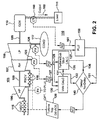
- FIG. 2 illustrates an exemplary steam turbine 105 and steam turbine control system 110 providing expanded turbine exhaust pressure limits during load loss conditions. It should be understood that the applicability of the present control scheme is not limited by the exemplary turbine configuration including units with and without reheat. In other turbine arrangements, pressure monitoring may be performed at other locations and other measurements and representations of steam flow and steam velocity at the last buckets may be provided.
- the steam turbine 105 includes a high-pressure steam turbine 106, a reheat steam turbine 107 crossing-over to a low-pressure steam turbine 108.
- the steam turbines may be coupled on a common shaft 109 to an electrical generator 110 and may also be coupled to a gas turbine (not shown).
- the electrical generator 110 outputs to a load 111, which may be local or a transmission system.
- Main steam control valves (MSCV) 115 provide for rapid isolation of the steam input to the high-pressure turbine 106.
- Reheat steam control valves (RSCV) 116 provide rapid isolation for steam to the reheat steam turbine.
- the low pressure turbine 108 exhausts to steam condenser 117.
- a turbine trip device 120 is provided to quickly close the steam supply to the high-pressure turbine 106 and reheat turbine 107.
- the turbine trip device 120 may receive trip signals from various other functions of the turbine control system (not shown) for the protection of the turbine systems.
- Instruments within the turbine system provide known inputs to the turbine control system for monitoring and protection of the turbines and other components.
- a pressure transmitter 125 for the turbine stage pressure between the RH turbine 107 and the LP steam turbine 108 and a pressure transmitter 126 for turbine exhaust pressure provide input to the turbine control system 110.
- LP inlet pressure (LPIP) 127 and turbine exhaust pressure 128 are provided to a calculation of VAN 130.
- the calculated VAN 131 and turbine exhaust pressure 128 are provided to a turbine exhaust trip calculation (also called vacuum trip) 135.
- the turbine exhaust pressure trip is provided directly to the turbine trip device for closing the MSCVs 115/RSCVs 116.
- the closing of the MSCVs/RSCVs s leads to extended and undesirable recovery time for the turbines.
- a time delay 140 may be provided to the exhaust pressure trips to allow continued operation under elevated transient exhaust pressure conditions that would otherwise result in exhaust pressure alarms and trips of the MSCVs/RHCVs.
- the time delay 140 allows transient protection logic to extend the allowable exhaust pressure during a load rejection condition.
- the load rejection condition may be determined by a power load unbalance (PLU) function 150.
- Current transformer 160 senses the electrical output from the generator 110.
- the PLU function 150 compares the generator electrical output 165 with the turbine load as determined by VAN 131.
- a PLU signal 151 is sent to the time delay circuitry 140. If a separate VAN signal 132 confirming a low load is sent to the time delay circuitry, then a time delay is imposed on the exhaust pressure alarms and trip. Under high turbine exhaust conditions, when delay conditions are not supported, turbine exhaust trip signal passes to the turbine trip device 120 without a delay. A more detailed description of the extended transient exhaust pressure protection logic will be described relative to FIG. 4 .
- FIG. 3 illustrates operational and trip limits for exhaust pressure versus last stage bucket annulus velocity, which incorporate both normal and transient exhaust pressure operation.
- Alarm curve 210 represents the steady state operational alarm limits for exhaust pressure as a function of VAN.
- Trip curve 220 represents the steady state exhaust pressure trip limits for exhaust pressure as a function of VAN.
- the shaded area 230 represents a time dependent, transient exhaust pressure operation region. The transient exhaust pressure operation area falls between a VAN of 0 and a VAN of Z, representing operation between full-speed no-load (FSNL) and house load, the expected operational conditions after a load rejection. Combined cycle units are expected to be at FSNL, as the gas turbine will usually be supplying plant auxiliary load.
- FSNL full-speed no-load
- the steam turbine would be carrying the plant auxiliary load, usually 4-6% of full load.
- the steady state protection logic will provide alarms and or trips as required based on the actual exhaust pressure and the allowed limits.
- the steady state protection logic should provide alarms and trips unless the transient protection logic is active. Operation according to the transient protective scheme is functional when the PLU function is activated by a load reduction greater than the PLU setting and the calculated VAN falls within the shaded region 230.
- Point 1 represents a unit operating at or close to full load. If a unit is at full load as indicated by Point 1, were to undergo a load rejection then system response would depend on the plant conditions that result.
- the unit is operating normally below normal alarm setting and trip settings.
- the unit is operating above the normal alarm setting 210, below the normal trip setting 220, and outside the transient exhaust pressure operation region 230.
- Transient exhaust pressure transient protection logic is not required for continued operation at Point 2.
- an immediate trip is initiated as the exhaust pressure exceeds the maximum trip setting, and is even above the exhaust pressure for transient exhaust pressure operation region 230.
- Operation at Point 4 within the transient exhaust pressure operation region 230, immediately initiates an alarm indicating that the transient trip delay is active, allowing operation in the region without a trip for the duration of a trip delay period.
- the turbine control system In determining the operating load VAN, the turbine control system will continue to use a turbine stage pressure as an indication of steam turbine last stage mass flow. Mass flow will be assumed to be linear with a measured pressure. The actual operating exhaust pressure may used to determine VAN. The control system will compare the operating VAN to the specific unit's VAN based limits. The control system will monitor exhaust pressure with both the traditional steady state and transient logic active. Z feet/sec represents the VAN zone for which the transient exhaust pressure protection logic could be active.
- the transient protection logic will be activated if the PLU function is activated by a load reduction greater than the PLU setting and the calculated VAN goes to a value less than a Z value.
- PLU provides the required load magnitude and rate change sensitivity required for determining a load rejection.
- generator load for example generator load amperes
- house load i.e., less than the Z-value
- the turbine control system will provide the necessary protection according to the location on the operating map. If the resulting operating point is in the time dependent transient exhaust pressure operation region 230, the turbine control system will monitor the operation time and if that operating time exceeds a predetermined value the turbine is to be tripped.
- the unit If the exhaust pressure drops below the lower end 240 of the transient exhaust pressure operation region 230 within the allotted time period, the unit is not be tripped and the transient protection logic is disabled to prevent drifting in and out of the time dependent zone.
- control valve closed, tripped, etc the transient exhaust pressure protection is deactivated. In the exemplary embodiment, this occurs when speed decays to 75% of rated speed, and is not reactivated until the load on the unit has reached the activation load.
- the control system may count the excursion as an incident and monitor the time period that the unit operates in the time dependent zone. The number of incidents may be recorded and times accumulated for each event and total, and archived.
- the control system may provide on the operator display, the unit's allowable exhaust pressure guideline VAN curve, and the real time operating point. Alarms may be annunciated and displayed.
- FIG. 4 illustrates an embodiment of a transient protection logic 400 for delay of the exhaust pressure trip under load rejection conditions.
- Turbine exhaust pressure 5 and LP inlet pressure (LPIP) 10 are sensed and provided to a VAN calculation 15.
- the calculated VAN 16 and the turbine exhaust pressure 6 are provided to the turbine exhaust pressure trip function 20 for the normal trip range. If turbine exhaust pressure 6 is above the trip level for the calculated VAN 6, a trip condition 21 is generated. If the trip condition 21 exists and a low value for delay signal 22 is generated, AND gate 25 blocks the trip logic signal 26 from passing to trip output 30 onto MSCV trip device 35. If the trip delay signal 22 is not generated or has timed out, then the MSCV trip device may be activated.
- LPIP LP inlet pressure
- Confirmatory logic for the trip delay signal 22 may be provided as follows.
- the determination of load rejection is provided at AND gate 55.
- VAN calculation signal 17 is provided to house load check 40 to determine if steam load has dropped to house load level that would exist after a turbine trip.
- House load confirmatory signal 41 is passed to AND gate 55.
- a load check 45 may be performed for a minimum load level to establish arming 46 of AND gate 55 for PLU event signal.
- the PLU 50 establishes the final input to AND gate 55.
- the PLU event 50 is determined by a drop of a predetermined value in electrical load output 49 relative to steam load as determined by LPIP 10.
- OR gate 75 may incorporate logic for boundary limits on expanded transient exhaust pressure limits.
- Exhaust pressure signal 7 is compared against a maximum allowable transient exhaust pressure limit 60 and a minimum allowable transient exhaust pressure limit 65. If the maximum or minimum allowable transient exhaust pressure are violated, then OR gate 75 is triggered. Likewise if turbine speed block 71 determines from turbine speed measurement 70 that the turbine speed has slowed to less than a predetermined fraction of full speed indicating that the turbine has likely tripped already, there is no need to prevent trip of the MSCV.
- AND gate 90 output 22 determines if AND gate 25 delays an exhaust pressure trip signal 21. A low state on AND gate 90 will cause AND gate 22 to output a trip signal immediately in response to a trip input condition. A high state on AND gate 90 will cause AND gate 22 to delay a trip signal.
- AND gate 90 to output a high state input 81 from OR gate 75 must be low (none of the inputs 60, 65 or 71 be active), input 96 from TDPU 95 be low (time delay must not have expired) and output 56 from OR gate 75 must be high (operating in the transient pressure boundary and turbine speed above designated value).
- OR gate 80 outputs a low if neither AND gate 90 output 22 is low nor AND gate 55 output is low.
- FIG. 5 illustrates a flowchart for a method of operating a steam turbine with expanded transient exhaust pressure protection limits.
- step 510 continuously monitor turbine operating parameters including turbine exhaust pressure, turbine vertical joint pressure, electrical load, turbine speed.
- step 520 calculate VAN.
- step 530 determine if turbine exhaust pressure exceeds normal state turbine exhaust pressure limits, then establish a turbine device trip signal in step 535.
- step 540 it is determined if a PLU event has occurred. Such event occurs, as previously described, when the PLU function is armed by generator load being above a predetermined level, and a drop in generator load occurs of a predetermined amount relative to turbine load, as determined by VAN.
- step 550 it is determined whether the calculated VAN is below a predetermined level that confirms the turbine is at house load.
- step 560 it is determined if turbine exhaust pressure exceeds the transient operating band.
- step 565 it is determined if turbine exhaust pressure is below the transient operating band.
- step 570 it is determined if turbine speed is below 75% of full speed, indicating that the turbine has tripped already. If any of these exceptions occur, then operation under the transient turbine exhaust limits should not continue and any active trip signal should be passed. Otherwise for steps 560, 565 and 570 conditions suggest that the active trip signal may be delayed for a predetermined time during operation in the transient exhaust pressure operation region. A delay timer for the predetermined time delay is started in step 575. If the timer has not time timed out, then an active trip signal is not passed. If the timer has timed out in step 580, it is decided in step 585 whether the trip signal is passed. An active trip signal is passed 590 through to the turbine trip device, causing the MSCVs to shut in step 595.
Landscapes
- Engineering & Computer Science (AREA)
- Chemical & Material Sciences (AREA)
- Combustion & Propulsion (AREA)
- Mechanical Engineering (AREA)
- General Engineering & Computer Science (AREA)
- Control Of Turbines (AREA)
Applications Claiming Priority (1)
| Application Number | Priority Date | Filing Date | Title |
|---|---|---|---|
| US12/649,800 US8556569B2 (en) | 2009-12-30 | 2009-12-30 | Method for operating steam turbine with transient elevated back pressure |
Publications (3)
| Publication Number | Publication Date |
|---|---|
| EP2345795A2 true EP2345795A2 (de) | 2011-07-20 |
| EP2345795A3 EP2345795A3 (de) | 2017-12-13 |
| EP2345795B1 EP2345795B1 (de) | 2021-11-03 |
Family
ID=44065646
Family Applications (1)
| Application Number | Title | Priority Date | Filing Date |
|---|---|---|---|
| EP10195193.7A Not-in-force EP2345795B1 (de) | 2009-12-30 | 2010-12-15 | Verfahren für den Betrieb von Dampfturbinen mit vorübergehend erhöhtem Gegendruck |
Country Status (4)
| Country | Link |
|---|---|
| US (1) | US8556569B2 (de) |
| EP (1) | EP2345795B1 (de) |
| CN (1) | CN102121403B (de) |
| RU (1) | RU2562340C2 (de) |
Cited By (1)
| Publication number | Priority date | Publication date | Assignee | Title |
|---|---|---|---|---|
| EP2642090A1 (de) * | 2012-03-19 | 2013-09-25 | MAN Diesel & Turbo SE | Dampfturbine und Verfahren zum Betrieb einer Dampfturbine |
Families Citing this family (17)
| Publication number | Priority date | Publication date | Assignee | Title |
|---|---|---|---|---|
| US8556569B2 (en) * | 2009-12-30 | 2013-10-15 | General Electric Company | Method for operating steam turbine with transient elevated back pressure |
| US9239576B2 (en) * | 2012-02-17 | 2016-01-19 | Fisher-Rosemount Systems, Inc. | Methods and apparatus to apply multiple trip limits to a device in a process control system |
| KR20140139607A (ko) * | 2012-03-30 | 2014-12-05 | 알스톰 테크놀러지 리미티드 | 가스 터빈 플랜트를 안전하게 운전하기 위한 방법 및 장치 |
| JP6295062B2 (ja) * | 2013-11-07 | 2018-03-14 | 三菱日立パワーシステムズ株式会社 | 蒸気タービンプラント起動制御装置 |
| US9496707B2 (en) * | 2014-12-22 | 2016-11-15 | Schweitzer Engineering Laboratories, Inc. | Generator protection element |
| US10156160B2 (en) * | 2016-10-24 | 2018-12-18 | General Electric Technology Gmbh | Systems and methods to control power plant operation via control of turbine run-up and acceleration |
| CN107228088B (zh) * | 2017-05-31 | 2019-02-01 | 上海明华电力技术工程有限公司 | 一种基于送风机系统状态监测的送风机rb控制方法 |
| CN107246401B (zh) * | 2017-05-31 | 2019-02-01 | 上海明华电力技术工程有限公司 | 一种基于引风机系统状态监测的引风机rb控制方法 |
| US10931097B2 (en) | 2017-09-25 | 2021-02-23 | Schweitzer Engineering Laboratories, Inc. | Generator stator ground protection using third harmonic |
| US10333291B2 (en) | 2017-09-25 | 2019-06-25 | Schweitzer Engineering Laboratories, Inc. | Multiple generator ground fault detection |
| US10797632B2 (en) | 2018-08-21 | 2020-10-06 | Schweitzer Engineering Laboratories, Inc. | Sensitive directional element for generator protection |
| CN110374694B (zh) * | 2019-06-05 | 2022-06-14 | 陕西渭河发电有限公司 | 一种高背压供热机组安全控制方法 |
| US10819261B1 (en) | 2019-10-25 | 2020-10-27 | Schweitzer Engineering Laboratories, Inc. | Security improvements for electric power generator protection |
| US11631972B2 (en) | 2020-12-16 | 2023-04-18 | Schweitzer Engineering Laboratories, Inc. | Accurate modeling of equipment overexcitation damage curves |
| CN113834056A (zh) * | 2021-08-31 | 2021-12-24 | 中国船舶重工集团公司第七0三研究所 | 一种锅炉上锅筒压力过高保护方法 |
| US11946966B1 (en) | 2023-02-20 | 2024-04-02 | Schweitzer Engineering Laboratories, Inc. | Selective stator ground fault protection using positive-sequence voltage reference |
| CN116291769B (zh) * | 2023-02-23 | 2026-02-24 | 华北电力科学研究院有限责任公司 | 背压与旁路供热安全保护控制方法及装置 |
Family Cites Families (15)
| Publication number | Priority date | Publication date | Assignee | Title |
|---|---|---|---|---|
| BE757455A (fr) * | 1969-10-16 | 1971-03-16 | Westinghouse Electric Corp | Systeme anti-emballement pour |
| CH589785A5 (de) * | 1974-05-31 | 1977-07-15 | Bbc Brown Boveri & Cie | |
| US4005581A (en) * | 1975-01-24 | 1977-02-01 | Westinghouse Electric Corporation | Method and apparatus for controlling a steam turbine |
| US4004424A (en) | 1975-05-16 | 1977-01-25 | Bechtel International Corporation | Method for limiting back pressure on steam turbine |
| SU1149037A1 (ru) * | 1983-11-22 | 1985-04-07 | Производственное Предприятие "Уралтехэнерго" Производственного Объединения По Наладке,Совершенствованию Технологии И Эксплуатации Электростанций И Сетей "Союзтехэнерго" | Способ защиты турбомашины при сбросе нагрузки |
| RU2112148C1 (ru) * | 1996-02-01 | 1998-05-27 | Григорий Давидович Баринберг | Способ работы теплофикационной турбины по тепловому графику |
| JP4230638B2 (ja) * | 2000-04-10 | 2009-02-25 | 株式会社東芝 | 原子力発電プラントの蒸気タービン制御装置 |
| JP3684208B2 (ja) * | 2002-05-20 | 2005-08-17 | 株式会社東芝 | ガスタービン制御装置 |
| US6865935B2 (en) * | 2002-12-30 | 2005-03-15 | General Electric Company | System and method for steam turbine backpressure control using dynamic pressure sensors |
| US7343744B2 (en) | 2005-07-27 | 2008-03-18 | General Electric Company | Method and system for controlling a reheat turbine-generator |
| US7470103B2 (en) * | 2006-02-24 | 2008-12-30 | General Electric Company | Method for determining limit exceedance |
| US7933101B2 (en) * | 2007-02-15 | 2011-04-26 | Aka Information Design | Generator power plant protection system and method |
| JP4699401B2 (ja) * | 2007-02-20 | 2011-06-08 | 三菱重工業株式会社 | 蒸気システムの制御方法及び制御装置 |
| JP4909294B2 (ja) * | 2008-02-05 | 2012-04-04 | 三菱重工業株式会社 | タービンバイパス制御装置及び制御方法 |
| US8556569B2 (en) * | 2009-12-30 | 2013-10-15 | General Electric Company | Method for operating steam turbine with transient elevated back pressure |
-
2009
- 2009-12-30 US US12/649,800 patent/US8556569B2/en not_active Expired - Fee Related
-
2010
- 2010-12-15 EP EP10195193.7A patent/EP2345795B1/de not_active Not-in-force
- 2010-12-28 RU RU2010153528/06A patent/RU2562340C2/ru active
- 2010-12-28 CN CN201010624374.2A patent/CN102121403B/zh not_active Expired - Fee Related
Non-Patent Citations (1)
| Title |
|---|
| None |
Cited By (1)
| Publication number | Priority date | Publication date | Assignee | Title |
|---|---|---|---|---|
| EP2642090A1 (de) * | 2012-03-19 | 2013-09-25 | MAN Diesel & Turbo SE | Dampfturbine und Verfahren zum Betrieb einer Dampfturbine |
Also Published As
| Publication number | Publication date |
|---|---|
| US20110158786A1 (en) | 2011-06-30 |
| EP2345795A3 (de) | 2017-12-13 |
| CN102121403A (zh) | 2011-07-13 |
| RU2010153528A (ru) | 2012-07-10 |
| US8556569B2 (en) | 2013-10-15 |
| RU2562340C2 (ru) | 2015-09-10 |
| CN102121403B (zh) | 2015-02-25 |
| EP2345795B1 (de) | 2021-11-03 |
Similar Documents
| Publication | Publication Date | Title |
|---|---|---|
| US8556569B2 (en) | Method for operating steam turbine with transient elevated back pressure | |
| EP2372482B1 (de) | Verfahren und System zum Testen eines Übergeschwindigkeitsschutzsystems einer Kraftwerksmaschine | |
| EP2466077A1 (de) | Dampfturbinen-Übergeschwindigkeitsschutz | |
| EP2372112B1 (de) | Verfahren zur Bestimmung, wann ein Test eines Übergeschwindigkeitsschutzsystems einer Kraftwerksmaschine durchzuführen ist | |
| GB1289030A (de) | ||
| JP5781312B2 (ja) | ガスタービンの信頼性評価試験方法 | |
| EP2806112A1 (de) | Vorrichtung zur erkennung von lastunwucht verfahren zur erkennung von lastunwucht | |
| US20060112697A1 (en) | Stall detection and recovery system | |
| JP5524906B2 (ja) | 蒸気タービンシステムの保護装置 | |
| US4053786A (en) | Transducer out of range protection for a steam turbine generator system | |
| US9976440B2 (en) | Method for testing an overspeed protection mechanism of a single-shaft combined-cycle plant | |
| KR101834099B1 (ko) | 단축 시스템의 과속도 보호 장치의 검사 방법 | |
| KR101144308B1 (ko) | 터빈 바이패스 설비를 갖춘 증기터빈의 과속도 예방 장치에서의 리셋 설정 방법 | |
| JP2018127987A (ja) | 2軸式ガスタービン発電システムおよび2軸式ガスタービン発電システムの制御方法 | |
| JP2613225B2 (ja) | タービン保護装置 | |
| JPS5812450B2 (ja) | タ−ビン保護装置 | |
| JP5889386B2 (ja) | ガスタービンの信頼性評価試験方法およびその装置 | |
| JPH06159008A (ja) | 蒸気タービン強制冷却装置の監視・保護および性能管理装置 | |
| RU2799266C1 (ru) | Способ защиты газотурбинного двигателя от раскрутки ротора силовой турбины и устройство для его осуществления | |
| JP2004060496A (ja) | 蒸気タービン制御装置 | |
| Schatzmann | Turbine Overspeed Control Behaviour | |
| JP2001254606A (ja) | 蒸気タービンの運転方法 | |
| Weaver | Reliable Overspeed Protection for Industrial Drive Turbines | |
| JP2002097904A (ja) | タービン制御装置 | |
| JPH02271004A (ja) | 低圧タービンバイパス弁制御装置 |
Legal Events
| Date | Code | Title | Description |
|---|---|---|---|
| PUAI | Public reference made under article 153(3) epc to a published international application that has entered the european phase |
Free format text: ORIGINAL CODE: 0009012 |
|
| AK | Designated contracting states |
Kind code of ref document: A2 Designated state(s): AL AT BE BG CH CY CZ DE DK EE ES FI FR GB GR HR HU IE IS IT LI LT LU LV MC MK MT NL NO PL PT RO RS SE SI SK SM TR |
|
| AX | Request for extension of the european patent |
Extension state: BA ME |
|
| PUAL | Search report despatched |
Free format text: ORIGINAL CODE: 0009013 |
|
| AK | Designated contracting states |
Kind code of ref document: A3 Designated state(s): AL AT BE BG CH CY CZ DE DK EE ES FI FR GB GR HR HU IE IS IT LI LT LU LV MC MK MT NL NO PL PT RO RS SE SI SK SM TR |
|
| AX | Request for extension of the european patent |
Extension state: BA ME |
|
| RIC1 | Information provided on ipc code assigned before grant |
Ipc: F01K 13/02 20060101AFI20171107BHEP |
|
| STAA | Information on the status of an ep patent application or granted ep patent |
Free format text: STATUS: REQUEST FOR EXAMINATION WAS MADE |
|
| 17P | Request for examination filed |
Effective date: 20180613 |
|
| RBV | Designated contracting states (corrected) |
Designated state(s): AL AT BE BG CH CY CZ DE DK EE ES FI FR GB GR HR HU IE IS IT LI LT LU LV MC MK MT NL NO PL PT RO RS SE SI SK SM TR |
|
| STAA | Information on the status of an ep patent application or granted ep patent |
Free format text: STATUS: EXAMINATION IS IN PROGRESS |
|
| 17Q | First examination report despatched |
Effective date: 20200511 |
|
| GRAP | Despatch of communication of intention to grant a patent |
Free format text: ORIGINAL CODE: EPIDOSNIGR1 |
|
| STAA | Information on the status of an ep patent application or granted ep patent |
Free format text: STATUS: GRANT OF PATENT IS INTENDED |
|
| INTG | Intention to grant announced |
Effective date: 20210608 |
|
| GRAS | Grant fee paid |
Free format text: ORIGINAL CODE: EPIDOSNIGR3 |
|
| GRAA | (expected) grant |
Free format text: ORIGINAL CODE: 0009210 |
|
| STAA | Information on the status of an ep patent application or granted ep patent |
Free format text: STATUS: THE PATENT HAS BEEN GRANTED |
|
| AK | Designated contracting states |
Kind code of ref document: B1 Designated state(s): AL AT BE BG CH CY CZ DE DK EE ES FI FR GB GR HR HU IE IS IT LI LT LU LV MC MK MT NL NO PL PT RO RS SE SI SK SM TR |
|
| REG | Reference to a national code |
Ref country code: GB Ref legal event code: FG4D |
|
| REG | Reference to a national code |
Ref country code: AT Ref legal event code: REF Ref document number: 1444127 Country of ref document: AT Kind code of ref document: T Effective date: 20211115 Ref country code: CH Ref legal event code: EP |
|
| REG | Reference to a national code |
Ref country code: IE Ref legal event code: FG4D |
|
| REG | Reference to a national code |
Ref country code: DE Ref legal event code: R096 Ref document number: 602010067757 Country of ref document: DE |
|
| REG | Reference to a national code |
Ref country code: LT Ref legal event code: MG9D |
|
| REG | Reference to a national code |
Ref country code: NL Ref legal event code: MP Effective date: 20211103 |
|
| REG | Reference to a national code |
Ref country code: AT Ref legal event code: MK05 Ref document number: 1444127 Country of ref document: AT Kind code of ref document: T Effective date: 20211103 |
|
| PG25 | Lapsed in a contracting state [announced via postgrant information from national office to epo] |
Ref country code: RS Free format text: LAPSE BECAUSE OF FAILURE TO SUBMIT A TRANSLATION OF THE DESCRIPTION OR TO PAY THE FEE WITHIN THE PRESCRIBED TIME-LIMIT Effective date: 20211103 Ref country code: LT Free format text: LAPSE BECAUSE OF FAILURE TO SUBMIT A TRANSLATION OF THE DESCRIPTION OR TO PAY THE FEE WITHIN THE PRESCRIBED TIME-LIMIT Effective date: 20211103 Ref country code: FI Free format text: LAPSE BECAUSE OF FAILURE TO SUBMIT A TRANSLATION OF THE DESCRIPTION OR TO PAY THE FEE WITHIN THE PRESCRIBED TIME-LIMIT Effective date: 20211103 Ref country code: BG Free format text: LAPSE BECAUSE OF FAILURE TO SUBMIT A TRANSLATION OF THE DESCRIPTION OR TO PAY THE FEE WITHIN THE PRESCRIBED TIME-LIMIT Effective date: 20220203 Ref country code: AT Free format text: LAPSE BECAUSE OF FAILURE TO SUBMIT A TRANSLATION OF THE DESCRIPTION OR TO PAY THE FEE WITHIN THE PRESCRIBED TIME-LIMIT Effective date: 20211103 |
|
| PG25 | Lapsed in a contracting state [announced via postgrant information from national office to epo] |
Ref country code: IS Free format text: LAPSE BECAUSE OF FAILURE TO SUBMIT A TRANSLATION OF THE DESCRIPTION OR TO PAY THE FEE WITHIN THE PRESCRIBED TIME-LIMIT Effective date: 20220303 Ref country code: SE Free format text: LAPSE BECAUSE OF FAILURE TO SUBMIT A TRANSLATION OF THE DESCRIPTION OR TO PAY THE FEE WITHIN THE PRESCRIBED TIME-LIMIT Effective date: 20211103 Ref country code: PT Free format text: LAPSE BECAUSE OF FAILURE TO SUBMIT A TRANSLATION OF THE DESCRIPTION OR TO PAY THE FEE WITHIN THE PRESCRIBED TIME-LIMIT Effective date: 20220303 Ref country code: PL Free format text: LAPSE BECAUSE OF FAILURE TO SUBMIT A TRANSLATION OF THE DESCRIPTION OR TO PAY THE FEE WITHIN THE PRESCRIBED TIME-LIMIT Effective date: 20211103 Ref country code: NO Free format text: LAPSE BECAUSE OF FAILURE TO SUBMIT A TRANSLATION OF THE DESCRIPTION OR TO PAY THE FEE WITHIN THE PRESCRIBED TIME-LIMIT Effective date: 20220203 Ref country code: NL Free format text: LAPSE BECAUSE OF FAILURE TO SUBMIT A TRANSLATION OF THE DESCRIPTION OR TO PAY THE FEE WITHIN THE PRESCRIBED TIME-LIMIT Effective date: 20211103 Ref country code: LV Free format text: LAPSE BECAUSE OF FAILURE TO SUBMIT A TRANSLATION OF THE DESCRIPTION OR TO PAY THE FEE WITHIN THE PRESCRIBED TIME-LIMIT Effective date: 20211103 Ref country code: HR Free format text: LAPSE BECAUSE OF FAILURE TO SUBMIT A TRANSLATION OF THE DESCRIPTION OR TO PAY THE FEE WITHIN THE PRESCRIBED TIME-LIMIT Effective date: 20211103 Ref country code: GR Free format text: LAPSE BECAUSE OF FAILURE TO SUBMIT A TRANSLATION OF THE DESCRIPTION OR TO PAY THE FEE WITHIN THE PRESCRIBED TIME-LIMIT Effective date: 20220204 Ref country code: ES Free format text: LAPSE BECAUSE OF FAILURE TO SUBMIT A TRANSLATION OF THE DESCRIPTION OR TO PAY THE FEE WITHIN THE PRESCRIBED TIME-LIMIT Effective date: 20211103 |
|
| REG | Reference to a national code |
Ref country code: DE Ref legal event code: R119 Ref document number: 602010067757 Country of ref document: DE |
|
| PG25 | Lapsed in a contracting state [announced via postgrant information from national office to epo] |
Ref country code: SM Free format text: LAPSE BECAUSE OF FAILURE TO SUBMIT A TRANSLATION OF THE DESCRIPTION OR TO PAY THE FEE WITHIN THE PRESCRIBED TIME-LIMIT Effective date: 20211103 Ref country code: SK Free format text: LAPSE BECAUSE OF FAILURE TO SUBMIT A TRANSLATION OF THE DESCRIPTION OR TO PAY THE FEE WITHIN THE PRESCRIBED TIME-LIMIT Effective date: 20211103 Ref country code: RO Free format text: LAPSE BECAUSE OF FAILURE TO SUBMIT A TRANSLATION OF THE DESCRIPTION OR TO PAY THE FEE WITHIN THE PRESCRIBED TIME-LIMIT Effective date: 20211103 Ref country code: EE Free format text: LAPSE BECAUSE OF FAILURE TO SUBMIT A TRANSLATION OF THE DESCRIPTION OR TO PAY THE FEE WITHIN THE PRESCRIBED TIME-LIMIT Effective date: 20211103 Ref country code: DK Free format text: LAPSE BECAUSE OF FAILURE TO SUBMIT A TRANSLATION OF THE DESCRIPTION OR TO PAY THE FEE WITHIN THE PRESCRIBED TIME-LIMIT Effective date: 20211103 Ref country code: CZ Free format text: LAPSE BECAUSE OF FAILURE TO SUBMIT A TRANSLATION OF THE DESCRIPTION OR TO PAY THE FEE WITHIN THE PRESCRIBED TIME-LIMIT Effective date: 20211103 |
|
| REG | Reference to a national code |
Ref country code: CH Ref legal event code: PL |
|
| PG25 | Lapsed in a contracting state [announced via postgrant information from national office to epo] |
Ref country code: MC Free format text: LAPSE BECAUSE OF FAILURE TO SUBMIT A TRANSLATION OF THE DESCRIPTION OR TO PAY THE FEE WITHIN THE PRESCRIBED TIME-LIMIT Effective date: 20211103 |
|
| PLBE | No opposition filed within time limit |
Free format text: ORIGINAL CODE: 0009261 |
|
| STAA | Information on the status of an ep patent application or granted ep patent |
Free format text: STATUS: NO OPPOSITION FILED WITHIN TIME LIMIT |
|
| REG | Reference to a national code |
Ref country code: BE Ref legal event code: MM Effective date: 20211231 |
|
| 26N | No opposition filed |
Effective date: 20220804 |
|
| GBPC | Gb: european patent ceased through non-payment of renewal fee |
Effective date: 20220203 |
|
| PG25 | Lapsed in a contracting state [announced via postgrant information from national office to epo] |
Ref country code: LU Free format text: LAPSE BECAUSE OF NON-PAYMENT OF DUE FEES Effective date: 20211215 Ref country code: IE Free format text: LAPSE BECAUSE OF NON-PAYMENT OF DUE FEES Effective date: 20211215 Ref country code: DE Free format text: LAPSE BECAUSE OF NON-PAYMENT OF DUE FEES Effective date: 20220701 Ref country code: AL Free format text: LAPSE BECAUSE OF FAILURE TO SUBMIT A TRANSLATION OF THE DESCRIPTION OR TO PAY THE FEE WITHIN THE PRESCRIBED TIME-LIMIT Effective date: 20211103 |
|
| PG25 | Lapsed in a contracting state [announced via postgrant information from national office to epo] |
Ref country code: SI Free format text: LAPSE BECAUSE OF FAILURE TO SUBMIT A TRANSLATION OF THE DESCRIPTION OR TO PAY THE FEE WITHIN THE PRESCRIBED TIME-LIMIT Effective date: 20211103 Ref country code: FR Free format text: LAPSE BECAUSE OF NON-PAYMENT OF DUE FEES Effective date: 20220103 Ref country code: BE Free format text: LAPSE BECAUSE OF NON-PAYMENT OF DUE FEES Effective date: 20211231 |
|
| PG25 | Lapsed in a contracting state [announced via postgrant information from national office to epo] |
Ref country code: LI Free format text: LAPSE BECAUSE OF NON-PAYMENT OF DUE FEES Effective date: 20211231 Ref country code: CH Free format text: LAPSE BECAUSE OF NON-PAYMENT OF DUE FEES Effective date: 20211231 |
|
| PG25 | Lapsed in a contracting state [announced via postgrant information from national office to epo] |
Ref country code: GB Free format text: LAPSE BECAUSE OF NON-PAYMENT OF DUE FEES Effective date: 20220203 |
|
| PG25 | Lapsed in a contracting state [announced via postgrant information from national office to epo] |
Ref country code: IT Free format text: LAPSE BECAUSE OF FAILURE TO SUBMIT A TRANSLATION OF THE DESCRIPTION OR TO PAY THE FEE WITHIN THE PRESCRIBED TIME-LIMIT Effective date: 20211103 Ref country code: HU Free format text: LAPSE BECAUSE OF FAILURE TO SUBMIT A TRANSLATION OF THE DESCRIPTION OR TO PAY THE FEE WITHIN THE PRESCRIBED TIME-LIMIT; INVALID AB INITIO Effective date: 20101215 Ref country code: CY Free format text: LAPSE BECAUSE OF FAILURE TO SUBMIT A TRANSLATION OF THE DESCRIPTION OR TO PAY THE FEE WITHIN THE PRESCRIBED TIME-LIMIT Effective date: 20211103 |
|
| PG25 | Lapsed in a contracting state [announced via postgrant information from national office to epo] |
Ref country code: MK Free format text: LAPSE BECAUSE OF FAILURE TO SUBMIT A TRANSLATION OF THE DESCRIPTION OR TO PAY THE FEE WITHIN THE PRESCRIBED TIME-LIMIT Effective date: 20211103 |
|
| PG25 | Lapsed in a contracting state [announced via postgrant information from national office to epo] |
Ref country code: TR Free format text: LAPSE BECAUSE OF FAILURE TO SUBMIT A TRANSLATION OF THE DESCRIPTION OR TO PAY THE FEE WITHIN THE PRESCRIBED TIME-LIMIT Effective date: 20211103 |
|
| PG25 | Lapsed in a contracting state [announced via postgrant information from national office to epo] |
Ref country code: MT Free format text: LAPSE BECAUSE OF FAILURE TO SUBMIT A TRANSLATION OF THE DESCRIPTION OR TO PAY THE FEE WITHIN THE PRESCRIBED TIME-LIMIT Effective date: 20211103 |