EP2345533A1 - Perforation forming device - Google Patents
Perforation forming device Download PDFInfo
- Publication number
- EP2345533A1 EP2345533A1 EP09814394A EP09814394A EP2345533A1 EP 2345533 A1 EP2345533 A1 EP 2345533A1 EP 09814394 A EP09814394 A EP 09814394A EP 09814394 A EP09814394 A EP 09814394A EP 2345533 A1 EP2345533 A1 EP 2345533A1
- Authority
- EP
- European Patent Office
- Prior art keywords
- plate
- film sheet
- loading plate
- vertical direction
- blade assembly
- Prior art date
- Legal status (The legal status is an assumption and is not a legal conclusion. Google has not performed a legal analysis and makes no representation as to the accuracy of the status listed.)
- Withdrawn
Links
Images



Classifications
-
- B—PERFORMING OPERATIONS; TRANSPORTING
- B65—CONVEYING; PACKING; STORING; HANDLING THIN OR FILAMENTARY MATERIAL
- B65B—MACHINES, APPARATUS OR DEVICES FOR, OR METHODS OF, PACKAGING ARTICLES OR MATERIALS; UNPACKING
- B65B61/00—Auxiliary devices, not otherwise provided for, for operating on sheets, blanks, webs, binding material, containers or packages
- B65B61/04—Auxiliary devices, not otherwise provided for, for operating on sheets, blanks, webs, binding material, containers or packages for severing webs, or for separating joined packages
- B65B61/12—Auxiliary devices, not otherwise provided for, for operating on sheets, blanks, webs, binding material, containers or packages for severing webs, or for separating joined packages by tearing along perforations or lines of weakness
-
- B—PERFORMING OPERATIONS; TRANSPORTING
- B26—HAND CUTTING TOOLS; CUTTING; SEVERING
- B26F—PERFORATING; PUNCHING; CUTTING-OUT; STAMPING-OUT; SEVERING BY MEANS OTHER THAN CUTTING
- B26F1/00—Perforating; Punching; Cutting-out; Stamping-out; Apparatus therefor
- B26F1/02—Perforating by punching, e.g. with relatively-reciprocating punch and bed
-
- B—PERFORMING OPERATIONS; TRANSPORTING
- B26—HAND CUTTING TOOLS; CUTTING; SEVERING
- B26F—PERFORATING; PUNCHING; CUTTING-OUT; STAMPING-OUT; SEVERING BY MEANS OTHER THAN CUTTING
- B26F1/00—Perforating; Punching; Cutting-out; Stamping-out; Apparatus therefor
- B26F1/02—Perforating by punching, e.g. with relatively-reciprocating punch and bed
- B26F1/14—Punching tools; Punching dies
-
- B—PERFORMING OPERATIONS; TRANSPORTING
- B65—CONVEYING; PACKING; STORING; HANDLING THIN OR FILAMENTARY MATERIAL
- B65B—MACHINES, APPARATUS OR DEVICES FOR, OR METHODS OF, PACKAGING ARTICLES OR MATERIALS; UNPACKING
- B65B61/00—Auxiliary devices, not otherwise provided for, for operating on sheets, blanks, webs, binding material, containers or packages
- B65B61/02—Auxiliary devices, not otherwise provided for, for operating on sheets, blanks, webs, binding material, containers or packages for perforating, scoring, slitting, or applying code or date marks on material prior to packaging
-
- B—PERFORMING OPERATIONS; TRANSPORTING
- B26—HAND CUTTING TOOLS; CUTTING; SEVERING
- B26D—CUTTING; DETAILS COMMON TO MACHINES FOR PERFORATING, PUNCHING, CUTTING-OUT, STAMPING-OUT OR SEVERING
- B26D1/00—Cutting through work characterised by the nature or movement of the cutting member or particular materials not otherwise provided for; Apparatus or machines therefor; Cutting members therefor
- B26D1/0006—Cutting members therefor
-
- B—PERFORMING OPERATIONS; TRANSPORTING
- B26—HAND CUTTING TOOLS; CUTTING; SEVERING
- B26D—CUTTING; DETAILS COMMON TO MACHINES FOR PERFORATING, PUNCHING, CUTTING-OUT, STAMPING-OUT OR SEVERING
- B26D1/00—Cutting through work characterised by the nature or movement of the cutting member or particular materials not otherwise provided for; Apparatus or machines therefor; Cutting members therefor
- B26D1/0006—Cutting members therefor
- B26D2001/006—Cutting members therefor the cutting blade having a special shape, e.g. a special outline, serrations
-
- B—PERFORMING OPERATIONS; TRANSPORTING
- B26—HAND CUTTING TOOLS; CUTTING; SEVERING
- B26D—CUTTING; DETAILS COMMON TO MACHINES FOR PERFORATING, PUNCHING, CUTTING-OUT, STAMPING-OUT OR SEVERING
- B26D3/00—Cutting work characterised by the nature of the cut made; Apparatus therefor
- B26D3/10—Making cuts of other than simple rectilinear form
-
- B—PERFORMING OPERATIONS; TRANSPORTING
- B26—HAND CUTTING TOOLS; CUTTING; SEVERING
- B26D—CUTTING; DETAILS COMMON TO MACHINES FOR PERFORATING, PUNCHING, CUTTING-OUT, STAMPING-OUT OR SEVERING
- B26D7/00—Details of apparatus for cutting, cutting-out, stamping-out, punching, perforating, or severing by means other than cutting
- B26D7/01—Means for holding or positioning work
- B26D7/02—Means for holding or positioning work with clamping means
- B26D7/025—Means for holding or positioning work with clamping means acting upon planar surfaces
-
- B—PERFORMING OPERATIONS; TRANSPORTING
- B26—HAND CUTTING TOOLS; CUTTING; SEVERING
- B26F—PERFORATING; PUNCHING; CUTTING-OUT; STAMPING-OUT; SEVERING BY MEANS OTHER THAN CUTTING
- B26F1/00—Perforating; Punching; Cutting-out; Stamping-out; Apparatus therefor
- B26F1/38—Cutting-out; Stamping-out
- B26F1/44—Cutters therefor; Dies therefor
- B26F2001/4481—Cutters therefor; Dies therefor having special lateral or edge outlines or special surface shapes, e.g. apertures
-
- B—PERFORMING OPERATIONS; TRANSPORTING
- B31—MAKING ARTICLES OF PAPER, CARDBOARD OR MATERIAL WORKED IN A MANNER ANALOGOUS TO PAPER; WORKING PAPER, CARDBOARD OR MATERIAL WORKED IN A MANNER ANALOGOUS TO PAPER
- B31B—MAKING CONTAINERS OF PAPER, CARDBOARD OR MATERIAL WORKED IN A MANNER ANALOGOUS TO PAPER
- B31B2155/00—Flexible containers made from webs
-
- B—PERFORMING OPERATIONS; TRANSPORTING
- B31—MAKING ARTICLES OF PAPER, CARDBOARD OR MATERIAL WORKED IN A MANNER ANALOGOUS TO PAPER; WORKING PAPER, CARDBOARD OR MATERIAL WORKED IN A MANNER ANALOGOUS TO PAPER
- B31B—MAKING CONTAINERS OF PAPER, CARDBOARD OR MATERIAL WORKED IN A MANNER ANALOGOUS TO PAPER
- B31B2155/00—Flexible containers made from webs
- B31B2155/003—Flexible containers made from webs starting from tubular webs
-
- B—PERFORMING OPERATIONS; TRANSPORTING
- B31—MAKING ARTICLES OF PAPER, CARDBOARD OR MATERIAL WORKED IN A MANNER ANALOGOUS TO PAPER; WORKING PAPER, CARDBOARD OR MATERIAL WORKED IN A MANNER ANALOGOUS TO PAPER
- B31B—MAKING CONTAINERS OF PAPER, CARDBOARD OR MATERIAL WORKED IN A MANNER ANALOGOUS TO PAPER
- B31B2160/00—Shape of flexible containers
- B31B2160/20—Shape of flexible containers with structural provision for thickness of contents
-
- B—PERFORMING OPERATIONS; TRANSPORTING
- B31—MAKING ARTICLES OF PAPER, CARDBOARD OR MATERIAL WORKED IN A MANNER ANALOGOUS TO PAPER; WORKING PAPER, CARDBOARD OR MATERIAL WORKED IN A MANNER ANALOGOUS TO PAPER
- B31B—MAKING CONTAINERS OF PAPER, CARDBOARD OR MATERIAL WORKED IN A MANNER ANALOGOUS TO PAPER
- B31B70/00—Making flexible containers, e.g. envelopes or bags
- B31B70/14—Cutting, e.g. perforating, punching, slitting or trimming
- B31B70/20—Cutting sheets or blanks
-
- Y—GENERAL TAGGING OF NEW TECHNOLOGICAL DEVELOPMENTS; GENERAL TAGGING OF CROSS-SECTIONAL TECHNOLOGIES SPANNING OVER SEVERAL SECTIONS OF THE IPC; TECHNICAL SUBJECTS COVERED BY FORMER USPC CROSS-REFERENCE ART COLLECTIONS [XRACs] AND DIGESTS
- Y10—TECHNICAL SUBJECTS COVERED BY FORMER USPC
- Y10T—TECHNICAL SUBJECTS COVERED BY FORMER US CLASSIFICATION
- Y10T83/00—Cutting
- Y10T83/929—Tool or tool with support
- Y10T83/9314—Pointed perforators
Definitions
- the present invention relates to an apparatus to form perforations to rip a package of sanitary articles and particularly to an apparatus to form a package adapted to pack a plurality of sanitary articles, for example, disposable diapers with perforations along which the package may be smoothly ripped to take the diaper out from the package.
- a package is made of a relative soft material such as polyethylene therein a plurality of disposable diapers compressed together.
- the package is previously formed with perforations along which the package may be ripped to take the diaper out from the package.
- the perforations for the package are formed by pressing a perforating blade assembly against a polyethylene film placed on an elastic plate until individual perforating blades run through the film and partially stick into an elastic plate.
- the film also bites into the elastic plate as the perforating blade assembly is pressed against the elastic plate, making it difficult for the individual blades to run through the film. If it is difficult for the individual blades to run through the film, a length of each slid defining each perforation might be unacceptably short or even some or all of the expected perforations might not be formed. With such defective perforations, the package can not be smoothly ripped.
- the individual perforating blades partially stick into the elastic plate and, in consequence, the blades may be damaged at a high frequency.
- a frequency at which the blades should be exchanged with fresh ones becomes and a production cost for the blades correspondingly increases.
- perforations refers to a series of sheet slits or small holes formed by cutting through the sheet so that the sheet may be continuously ripped along such short slits or small holes.
- the improvement according to the present invention is characterized in that the apparatus further comprises a pressure plate opposed to the loading plate and adapted to press the film sheet against the loading plate, the loading plate has a slit formed through the loading plate adapted to be engaged with the perforating blade assembly, and the pressure plate is provided on its surface opposed to the film sheet with an anti-slip means.
- the perforating blade assembly is held by a blade holding plate, a biasing means is provided between the blade holding plate and the pressure plate to bias these blade holding plate and the pressure plate in the vertical direction, and the holding plate is adapted to move the perforating blade assembly into the slit formed through the loading plate against a biasing effect of the biasing means.
- the surface of the loading plate opposed to the film sheet is elastic at least in the vertical direction.
- the loading plate itself is provided on its surface opposed to the film sheet with an anti-slip means.
- the perforating blade assembly comprises a plurality of individual blades arranged in a line and each of the individual blades comprises a pointed tip facing the film sheet, a pair of oblique edges obliquely extending from the pointed tip in the vertical direction and a transverse direction orthogonal to the vertical direction wherein the oblique edges gradually draw apart one another in the transverse direction as they come upward in the vertical direction and a pair of parallel lateral edges extending upward from respective upper ends of the oblique edges in the vertical direction.
- At least a range of the individual blade extending from the pointed tip to the parallel lateral edges is movable into the slit formed through the loading plate.
- the pressure plate has a slit formed through said pressure plate in its thickness direction and having a substantially same shape as the slit formed through the loading plate, and the individual blades are adapted to pass through the slit formed through the pressure plate and then to be engaged with the slit formed through the loading plate.
- two or more layers of the film sheet are put flat together in a thickness direction thereof and loaded on the loading plate.
- the film sheet loaded on the loading plate may be pressed by the anti-slip means as a part of the pressure plate against the loading plate and simultaneously cut through by the perforating blade assembly to form the perforations to restrict the film sheet from being curled into the loading plate.
- the loading plate is formed with the slit adapted to be engaged with the perforating blade assembly so that the film sheet may be formed with the perforations as the perforating blade assembly moves into this slit.
- the individual blades would not move downward beyond the depth of the slit of the loading plate and stick the base plate. In other words, it is possible to protect the individual blades from being damaged due to sticking the loading plate, thus to reduce a frequency at which the perforating blade assemble must be exchanged with fresh blade assembly and thereby to reduce the production cost.
- Fig. 1 is a perspective view of a package 1 containing therein a plurality of disposable diapers and Fig. 2 is a plan view of the package 1 in a collapsed state before the diapers are packed.
- the package 1 is shaped in generally rectangular parallelepiped and is formed in the vicinity of one of its four corners with perforations 11 along which the package 1 is ripped so that the individual diapers contained therein are smoothly taken out one by one.
- the package 1 is formed of a film sheet 14 made of, for example, low density polyethylene (LDPE) having flexibility.
- LDPE low density polyethylene
- the package 1 is formed with the perforations 11 in a collapsed state. As illustrated, the film sheet 14 is initially annular and diametrically opposite segments thereof are folded inward, i.e., gusseted.
- One of these gusseted segments each comprising four layers is formed with the perforations 11.
- the package 1 may be opened from its collapsed state and filled with a plurality of disposable diapers to expose the perforations 11 comprising a pair of first segments 12 vertically extending symmetrically about one of four vertical edge lines and a second segment 13 connecting these two first segments with each other.
- FIG. 3 is a perspective view showing an apparatus 20 to form the perforations as partially broken away for convenience of illustration.
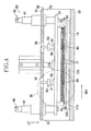
- Fig. 4 is a side view of the apparatus 20 of Fig. 3 as viewed in a cross direction CD.
- the apparatus 20 has a vertical direction Y and a transverse direction orthogonal to the this direction Y wherein the term "transverse direction” used herein should be construed to be defined by a machine direction MD in which the film sheet 14 as the material for the package 1 is fed and the cross direction CD orthogonal to the machine direction MD.
- the vertical direction Y is a direction extending through the film sheet 14 being fed in its thickness direction.
- the apparatus 20 comprises a housing 30, a plurality of plates contained within the housing 30 and a driving mechanism 40 provided outside the housing 30 to move some of the plates up and down.
- the housing 30 has a top wall 31, a bottom wall 32 both as viewed in the vertical direction Y and two side walls 33 opposed to each other in the cross direction CD.
- this mechanism 40 may be implemented in the form of a hydraulic control mechanism.
- a holding plate 60 for a perforating blade assembly 70 is provided below the top plate 50 as viewed in the vertical direction Y.
- the blade assembly holding plate 60 is fixed to the top plate 50 so as to be operatively associated with the top plate 50 and to move up and down.
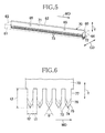
- Fig. 5 is a perspective view of the perforating blade assembly 70 wherein the blade assembly holding plate 60 is indicated by an imaginary line.
- Fig. 6 is a diagram illustrating a part of Fig. 5 in an enlarged scale.
- the blade assembly holding plate 60 includes opposite side walls 61, 62 extending in the machine direction MD and front and rear end walls 63, 64 extending in the cross direction CD. Under the blade assembly holding plate 60 in the vertical direction Y, the perforating blade assembly 70 is provided under the blade assembly holding plate 60 in the vertical direction Y.
- the perforating blade assembly 70 has a first segment 71 extending from the front end 63 toward the rear end 64 and a second segment 72 curving at the vicinity of the rear end 64 of the first segment 71 so as to extend in the cross direction CD.
- the perforating blade assembly 70 has a generally L-shaped.
- the first segment 71 adapted to form a first segments 12 of the perforations and the second segment 72 is adapted to form the second segment 13 of the perforations 11 (See Figs. 1 and 2 ).
- the perforating blade assembly 70 comprises a plurality of individual blades 73 each extending in the vertical direction Y.
- Each of these individual blades 73 has, as viewed in the vertical direction Y from the bottom, a pointed tip 74, opposite oblique edges 75 extending upward obliquely from the pointed tip 74 so as to be gradually drawn apart from each other in the machine direction MD and opposite parallel edges 76 extending upward in parallel to each other from respective ends of the oblique edges 75 in the vertical direction Y.
- the individual blade 73 has its thickness gradually thinned toward its periphery to form a sharp blade adapted to cleave the film sheet 14 and thereby to shape an individual slit.
- the parallel lateral edges extend further upward in the vertical direction to define a basal portion 77 adapted to be held by the blade assembly holding plate 60.
- the respective basal portions 77 have no sharp edge which would cleave the film sheet 14.
- the oblique edges 75 of the individual blade are drawn apart from each other around the associated pointed tip 74 at an angle ⁇ of about 60° so as to define part of an isosceles triangle.
- a dimension t1 by which each of the blades 73 is spaced from the adjacent blade 73 as measured between the parallel lateral edges 76 of these adjacent blades 73 directly opposed to each other is about 1.5 mm
- a width dimension t2 of the blade 73 as measured in the machine direction MD is about 3 mm
- a thickness dimension of the blade 73 as measured in the cross direction CD is about 0.7 mm.
- a length dimension t3 of the blade 73 as measured from the upper end of the basal portion 77 to the pointed tip 74 in the vertical direction Y is about 10 mm. It should be appreciated here that the dimension t1 specified above is with respect to the first segment 71 and the dimension t1 with respect to the second segment 72 is about 2 mm. It should be also appreciated that, with respect to the second segment 72, the thickness dimension of the blade 73 is given as measured in the machine direction MD. The other dimensions are common to these two segments 71, 72.
- a pressure plate 80 comprising a base layer 81 as an upper component as viewed in the vertical direction Y and a rubber layer 82 as a lower component as viewed in the vertical direction Y.
- the base layer 81 may be made of suitable metallic materials such as stainless steels and the rubber layer 82 may be made of silicon rubbers.
- the rubber layer 82 serves as anti-slip means for the film sheet 14.
- Such pressure plate 80 is attached to the top plate 50 by the intermediary of a pair of shafts 91, 91.
- the blade assembly holder plate 60 is interposed between the pressure plate 80 and the top plate 50 and formed with shaft-holes through which the respective shafts 91, 91 are slidably moved.
- biasing means 90 serving to bias these plates 50, 80 in the vertical direction Y.
- the biasing means 90 may be implemented in the form of a coil spring mounted around the shafts 91, 91, respectively.
- Fig. 7 is a plan view of the pressure plate 80 having side edges 83, 84 extending in the machine direction MD and front and rear ends 85, 86 extending in the cross direction CD.
- the pressure plate 80 is formed with a slit 87 extending through the pressure plate 80 in the thickness direction, i.e., in the vertical direction Y.
- This slit 87 has a shape substantially the same as the shape of the perforating blade assembly 70 so that the individual blades may collectively pass through this slit 87.
- the slit 87 formed through the pressure plate 80 comprises a first segment 88 extending in the machine direction MD from the front end 85 toward the rear end 86 and a second segment 89 extending in the cross direction CD from the vicinity of the rear end 86 of the first segment 88 toward the side edge 83 so that the first segment 88 cooperates with the second segment 89 to describe a generally L-like shape.
- a width dimension of this slit 87 formed through the pressure plate 80 is larger than the thickness dimension of the individual blades 73. Such relative dimension allows the perforating blade assembly 70 to pass through the slit 87 of the pressure plate 80.
- a loading plate 100 on which the film sheet 14 can be loaded.
- Fig. 8 is a plan view of the loading plate 100.
- the loading plate 100 has side edges 101, 102 extending in the machine direction MD and front and rear ends 103, 104 extending in the cross direction CD.
- the loading plate 100 is formed with a slit 105 extending through the loading plate 100 in the thickness direction, i.e., in the vertical direction Y.
- This slit 105 has a shape substantially the same as the shape of the perforating blade assembly 70 as well as of the slit 87 formed through the pressure plate 80.
- the slit 105 formed through the loading plate 100 comprises a first segment 106 extending in the machine direction MD from the front end 103 toward the rear end 104 and a second segment 107 extending from the vicinity of the rear end 104 of the first segment 106 in the cross direction CD so as to describe a curve so that the first segment 106 cooperates with the second segment 107 to describe a generally L-like shape.
- the loading plate 100 is made of urethane having hardness Hs of 90, elasticity at least in the vertical direction Y and serves as anti-slip means for the loading plate 100. Hardness of the loading plate 100 is measured in accordance with JIS Z 2246.
- the base plate 110 is formed with no slit and serves to close the slit 105 formed through the loading plate 100.
- the base plate 110 may be made of urethane similar to the material for the loading plate 100. However, it should be appreciated that the base plate 110 may be made of any kind of materials other than urethane so far as the slit formed through the loading plate 100 can be effectively closed.
- the base plate 110 has its bottom surface fixed to the bottom wall 32 of the housing 30. In this way, the loading plate 100 and the base plate 110 are integrally fixed to the housing 30.
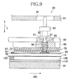
- Fig. 9 shows the encircled region IX in Fig. 4 in an enlarged scale and partially in a sectional view.
- the film sheet 14 is fed to the apparatus 20 and loaded on the loading plate 100.
- the driving mechanism (not shown) drives the top plate 50 and the blade assembly holding plate 60 to move downward in the vertical direction Y.
- the pressure plate 80 is coupled to the top plate 50 by the shaft 91.
- the top plate 50 is provided on its upper surface as viewed in the vertical direction Y with a holder 92 adapted to stabilize an upper portion of the shaft 91 so that the shaft 91 would be slidably moved through the shaft-hole 51 formed through the top plate 50.
- the lower end of the shaft 91 is fixed to the pressure plate 80.
- the shaft 91 extends through the shaft-hole 65 which has a diameter larger than that of the shaft-hole 51. Such differential diameter forms a step between these two shaft-holes 51, 65.
- the shaft-hole 65 formed through the blade assembly holding plate 60 is provided with the biasing means 90 having its upper end held in contact with the bottom surface of the top plate 50 and its lower end held in contact with the pressure plate 80 so as to bias both the top plate 50 and the pressure plate 80 in the vertical direction Y.
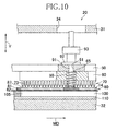
- the pressure plate 80 includes the rubber layer 82 defining the lower surface of the pressure plate 80 and this rubber layer 82 comes in contact with the film sheet 14 loaded on the loading plate 100. In this way, the film sheet 14 is sandwiched between the rubber layer 82 of the pressure plate 80 and the loading plate 100.
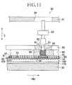
- Fig. 11 illustrates a state after the top plate 50 has been further pressed down in the vertical direction Y from the state illustrated in Fig. 10 .
- the top plate 50 moves downward together with the blade assembly holding plate 60 with the biasing means 90 being forcibly bowed down in the vertical direction Y and the holder 92 being spaced from a stopper 93.
- the biasing means 90 is forced by the bottom surface of the top plate 50 and the top surface of the base layer 81 constituting the pressure plate 80 to be bowed in the vertical direction Y, the perforating blade assembly 70 pass through the slit 87 of the pressure plate 80 into the slit 105 of the loading plate 100.
- the perforating blade assembly 70, the slit 87 of the pressure plate 80 and the slit 105 of the loading plate 100 are formed so as to present substantially the same shape so that the perforating blade assembly 70 may pass through the slit 87 of the pressure plate 70 into the slit 105 of the loading plate 100 without coming in contact with both the pressure plate 80 and the loading plate 100.
- the film sheet 14 sandwiched between the pressure plate 80 and the loading plate 100 can be formed with the slits corresponding to the individual blades 73 and these slits define the desired perforations.
- the pressure plate 80 is pressed down toward the loading plate 100 against a biasing force of the biasing means 90 and thereby the film sheet 14 interposed between the pressure plate 80 and the loading plate 100 is pressed against the loading plate 100 so as to be securely held between these pressure plate 80 and the loading plate 100.
- these layers of the film sheet 14 which otherwise would be apt to slip with respect to one another can be held together by pressing against one another and thereby prevented from being displaced with one another due to relative slippage.
- the perforating blade assembly 70 can reliably cut through the film sheet 14 and it is ensured that the slits each having a predetermined length corresponding to the width dimension of the individual blade can be formed on the film sheet 14. These slits each having the predetermined length assures that the film sheet 14 can be smoothly ripped along the perforations without an anxiety that any one or more of the perforations might make it difficult to rip the film sheet 14.
- the length dimension t3 of the individual blade 73 is set to be larger than a sum of the dimension of the pressure plate 80 as measured in the vertical direction Y and the thickness dimension of the film sheet 14 as measured in the vertical direction Y but to be smaller than a sum of the thickness dimension of the pressure plate 80, the thickness dimension of the film sheet 14 and a depth dimension t4 as measured in the vertical direction Y from the slit 105 of the loading plate 100 to the base plate 110. Consequently, the individual blades 73 reliably cut through the film sheet 14 without a possibility that the individual blades 73 might move downward beyond the depth of the slit 105 of the loading plate 100 and stick the base plate 110. In other words, it is possible to protect the individual blades 73 from being damaged due to sticking the base plate 110, thus to reduce a frequency at which the individual blades 73 must be exchanged with fresh blades and thereby to reduce the production cost.
- the film sheet 14 is held between the anti-slip means provided on the pressure plate 80 and the anti-slip means provided on the loading plate 100 to assure that the film sheet 14 is further reliably prevented from being relatively displaced from one another and thus the perforations can be reliably formed.
- the individual blade 73 is of a so-called double edged type having a pair of the oblique edges 75 opposed to each other in the machine direction MD so that the slit would be enlarged from the pointed tip 74 outward as the blade 73 cut through the film sheet 14.
- the length dimension of the oblique edge can be shortened and thereby the parallel lateral edges can be smoothly moved down to the film sheet 14.
- the parallel lateral edges 76 of all the individual blades evenly move down to the film sheet 14 and it is assured thereby that the slits each having the predetermined length can be formed by the respective individual blades 73.
- the apparatus according to the invention it is possible for the apparatus according to the invention to obtain the slits each having the predetermined length and therefore even when the film sheet 14 folded into a plurality of layers must be formed with the perforations, the film sheet 14 can be prevented from being made difficult to be smoothly ripped along the perforations.
- the individual perforating blades could not completely cut through the lower layers of the folded film sheet and, as a consequence, the lengths of the respective slits might be uneven.
- Such problem is solved, according to the present invention, by securely squeezing the folded film sheet 14 between the pressure plate 80 and the loading plate 100 and then using the individual blades 73 as have been described above to form the slits.
- the individual blades 73 reliably cut through the film sheet 14 including the lower layers thereof to length-equalize the individual slits formed thereby. Furthermore, the length dimension of the parallel lateral edges 76 may be shortened to reduce a dimension by which the loading plate 100 and the blade assembly holding plate 60 are apart from one another and thereby to downsize the apparatus.
- the loading plate 100 is made of urethane and elastic at least in the vertical direction Y.
- the elasticity of the loading plate 100 cooperates with the elasticity of the rubber layer 82 to squeeze the film sheet 14 and securely hold it.
- the elasticity of the loading plate 100 in the vertical direction Y also serves to buffer an impact due to collision of the pressure plate 80 with the loading plate 100.
- the loading plate 100 has the hardness Hs of 90 in the case of this particular embodiment, the hardness Hs is not limited to this value so far as the film sheet 14 is securely held without deformation of the slit 105 of the loading plate 100 due to a pressing force of the pressure plate 80.
- a spring mounted on the upper side of the pressure plate 80 as the biasing means 90 must have a spring constant sufficient to prevent the film sheet 14 from being displaced. While the loading plate 100 itself functions as the anti-slip means according to this particular embodiment, it is possible to attach any separate anti-slip means to the loading plate 100.
- the present invention is not limited to such arrangement.
- the present invention is applicable to any other arrangement of the individual blades 73.
- rubber and urethane are used as the anti-slip means in the case of the illustrated embodiment, the present invention is not limited to them and any other appropriate material may be used so far as the selected material is able to squeeze and thereby to hold the film sheet and has a sufficiently high frictional force with respect to the film sheet to restrict slippage of the film sheet.
- the distance by which the perforating blade assembly 70 is movable downward in the vertical direction Y may be adjusted to determine the number of the layers to be formed with the slits along which the film sheet 14 can be ripped.
Landscapes
- Engineering & Computer Science (AREA)
- Mechanical Engineering (AREA)
- Life Sciences & Earth Sciences (AREA)
- Forests & Forestry (AREA)
- Auxiliary Devices For And Details Of Packaging Control (AREA)
- Perforating, Stamping-Out Or Severing By Means Other Than Cutting (AREA)
- Packages (AREA)
Abstract
Description
- The present invention relates to an apparatus to form perforations to rip a package of sanitary articles and particularly to an apparatus to form a package adapted to pack a plurality of sanitary articles, for example, disposable diapers with perforations along which the package may be smoothly ripped to take the diaper out from the package.
- Conventionally, packages adapted to pack a plurality of disposable diapers such as sanitary articles therein in a face-to-face fashion is known. For example, in
PATENT DOCUMENT 1, a package is made of a relative soft material such as polyethylene therein a plurality of disposable diapers compressed together. The package is previously formed with perforations along which the package may be ripped to take the diaper out from the package. - In the case of this known example, the perforations for the package are formed by pressing a perforating blade assembly against a polyethylene film placed on an elastic plate until individual perforating blades run through the film and partially stick into an elastic plate. However, the film also bites into the elastic plate as the perforating blade assembly is pressed against the elastic plate, making it difficult for the individual blades to run through the film. If it is difficult for the individual blades to run through the film, a length of each slid defining each perforation might be unacceptably short or even some or all of the expected perforations might not be formed. With such defective perforations, the package can not be smoothly ripped. Furthermore, for every cycle of forming the perforations, the individual perforating blades partially stick into the elastic plate and, in consequence, the blades may be damaged at a high frequency. A frequency at which the blades should be exchanged with fresh ones becomes and a production cost for the blades correspondingly increases.
- In view of the problem left by the prior art unsolved behind as has been described above, it is an object of the present invention to provide an improved apparatus to form the perforations along which packages can be smoothly ripped, on one hand, and leading to a cost saving for production of the packages.
- The object set forth above is achieved, according to the present invention, by an improvement in an apparatus to form perforations comprising a loading plate on which a film sheet can be loaded, a perforating blade assembly adapted to form the film sheet with the perforations and a driving mechanism serving to move the perforating blade assembly up and down in a vertical direction so as to cut through the film sheet. The term "perforations" used herein refers to a series of sheet slits or small holes formed by cutting through the sheet so that the sheet may be continuously ripped along such short slits or small holes.
- The improvement according to the present invention is characterized in that the apparatus further comprises a pressure plate opposed to the loading plate and adapted to press the film sheet against the loading plate, the loading plate has a slit formed through the loading plate adapted to be engaged with the perforating blade assembly, and the pressure plate is provided on its surface opposed to the film sheet with an anti-slip means.
- According to one preferred embodiment, the perforating blade assembly is held by a blade holding plate, a biasing means is provided between the blade holding plate and the pressure plate to bias these blade holding plate and the pressure plate in the vertical direction, and the holding plate is adapted to move the perforating blade assembly into the slit formed through the loading plate against a biasing effect of the biasing means.
- According to another preferred embodiment, the surface of the loading plate opposed to the film sheet is elastic at least in the vertical direction.
- According to still another preferred embodiment, the loading plate itself is provided on its surface opposed to the film sheet with an anti-slip means.
- According to yet another preferred embodiment, the perforating blade assembly comprises a plurality of individual blades arranged in a line and each of the individual blades comprises a pointed tip facing the film sheet, a pair of oblique edges obliquely extending from the pointed tip in the vertical direction and a transverse direction orthogonal to the vertical direction wherein the oblique edges gradually draw apart one another in the transverse direction as they come upward in the vertical direction and a pair of parallel lateral edges extending upward from respective upper ends of the oblique edges in the vertical direction.
- According to further another preferred embodiment, at least a range of the individual blade extending from the pointed tip to the parallel lateral edges is movable into the slit formed through the loading plate.
- According to an alternative preferred embodiment, the pressure plate has a slit formed through said pressure plate in its thickness direction and having a substantially same shape as the slit formed through the loading plate, and the individual blades are adapted to pass through the slit formed through the pressure plate and then to be engaged with the slit formed through the loading plate.
- According to another preferred embodiment, two or more layers of the film sheet are put flat together in a thickness direction thereof and loaded on the loading plate.
- The film sheet loaded on the loading plate may be pressed by the anti-slip means as a part of the pressure plate against the loading plate and simultaneously cut through by the perforating blade assembly to form the perforations to restrict the film sheet from being curled into the loading plate. As a consequence, it is possible to form the film sheet with the perforations, each having the predetermined length, along which the package can be smoothly ripped. The loading plate is formed with the slit adapted to be engaged with the perforating blade assembly so that the film sheet may be formed with the perforations as the perforating blade assembly moves into this slit. The individual blades would not move downward beyond the depth of the slit of the loading plate and stick the base plate. In other words, it is possible to protect the individual blades from being damaged due to sticking the loading plate, thus to reduce a frequency at which the perforating blade assemble must be exchanged with fresh blade assembly and thereby to reduce the production cost.
-
- [
FIG. 1] Fig. 1 is a perspective view of a package. - [
FIG. 2] Fig. 2 is a plan view of the package. - [
FIG. 3] Fig. 3 is a perspective view of an apparatus to form perforations. - [
FIG. 4] Fig. 4 is a front view of the apparatus. - [
FIG. 5] Fig. 5 is a perspective view of a perforating blade assembly. - [
FIG. 6] Fig. 6 is a diagram illustrating the individual perforating blades in an enlarged scale. - [
FIG. 7] Fig. 7 is a plan view of a pressure plate. - [
FIG. 8] Fig. 8 is a plan view of a loading plate. - [
FIG. 9] Fig. 9 is a scale-enlarged view of an encircled region IX inFig. 4 . - [
FIG. 10] Fig. 10 is a diagram illustrating how the apparatus operates. - [
FIG. 11] Fig. 11 is a diagram illustrating how the apparatus operates. -
- 1
- package
- 11
- perforations
- 14
- film sheet
- 20
- apparatus
- 40
- driving mechanism
- 50
- top plate
- 60
- blade holding plate
- 70
- perforating blades
- 73
- individual blades
- 74
- pointed tip
- 75
- oblique edges
- 76
- parallel lateral edges
- 80
- pressure plate
- 82
- rubber layer (anti-slip means)
- 87
- pressure pate's slit
- 90
- biasing means
- 100
- loading plate
- 105
- loading plate's slit
-
Fig. 1 is a perspective view of apackage 1 containing therein a plurality of disposable diapers andFig. 2 is a plan view of thepackage 1 in a collapsed state before the diapers are packed. Thepackage 1 is shaped in generally rectangular parallelepiped and is formed in the vicinity of one of its four corners withperforations 11 along which thepackage 1 is ripped so that the individual diapers contained therein are smoothly taken out one by one. Thepackage 1 is formed of afilm sheet 14 made of, for example, low density polyethylene (LDPE) having flexibility. Thepackage 1 is formed with theperforations 11 in a collapsed state. As illustrated, thefilm sheet 14 is initially annular and diametrically opposite segments thereof are folded inward, i.e., gusseted. One of these gusseted segments each comprising four layers is formed with theperforations 11. After thepackage 1 ofsuch film sheet 14 has been formed with theperforations 11, thepackage 1 may be opened from its collapsed state and filled with a plurality of disposable diapers to expose theperforations 11 comprising a pair offirst segments 12 vertically extending symmetrically about one of four vertical edge lines and asecond segment 13 connecting these two first segments with each other. - One embodiment of the apparatus to form the
perforations 11 in the package, will be described.Fig. 3 is a perspective view showing anapparatus 20 to form the perforations as partially broken away for convenience of illustration.Fig. 4 is a side view of theapparatus 20 ofFig. 3 as viewed in a cross direction CD. Theapparatus 20 has a vertical direction Y and a transverse direction orthogonal to the this direction Y wherein the term "transverse direction" used herein should be construed to be defined by a machine direction MD in which thefilm sheet 14 as the material for thepackage 1 is fed and the cross direction CD orthogonal to the machine direction MD. The vertical direction Y is a direction extending through thefilm sheet 14 being fed in its thickness direction. - The
apparatus 20 comprises ahousing 30, a plurality of plates contained within thehousing 30 and adriving mechanism 40 provided outside thehousing 30 to move some of the plates up and down. Thehousing 30 has atop wall 31, abottom wall 32 both as viewed in the vertical direction Y and twoside walls 33 opposed to each other in the cross direction CD. Below thetop wall 31 of thehousing 30, i.e., within thehousing 30, there is provided atop plate 50 operatively associated with aslide bearing 41 constituting thedriving mechanism 40 so as to be moved up and down in the vertical direction. Although details of thedriving mechanism 40 are not illustrated, thismechanism 40 may be implemented in the form of a hydraulic control mechanism. Below thetop plate 50 as viewed in the vertical direction Y, there is provided a holdingplate 60 for aperforating blade assembly 70. The bladeassembly holding plate 60 is fixed to thetop plate 50 so as to be operatively associated with thetop plate 50 and to move up and down. -
Fig. 5 is a perspective view of the perforatingblade assembly 70 wherein the bladeassembly holding plate 60 is indicated by an imaginary line.Fig. 6 is a diagram illustrating a part ofFig. 5 in an enlarged scale. The bladeassembly holding plate 60 includesopposite side walls rear end walls assembly holding plate 60 in the vertical direction Y, the perforatingblade assembly 70 is provided. The perforatingblade assembly 70 has afirst segment 71 extending from thefront end 63 toward therear end 64 and asecond segment 72 curving at the vicinity of therear end 64 of thefirst segment 71 so as to extend in the cross direction CD. In this manner, the perforatingblade assembly 70 has a generally L-shaped. Thefirst segment 71 adapted to form afirst segments 12 of the perforations and thesecond segment 72 is adapted to form thesecond segment 13 of the perforations 11 (SeeFigs. 1 and2 ). - The perforating
blade assembly 70 comprises a plurality ofindividual blades 73 each extending in the vertical direction Y. Each of theseindividual blades 73 has, as viewed in the vertical direction Y from the bottom, apointed tip 74, opposite oblique edges 75 extending upward obliquely from the pointedtip 74 so as to be gradually drawn apart from each other in the machine direction MD and oppositeparallel edges 76 extending upward in parallel to each other from respective ends of the oblique edges 75 in the vertical direction Y. Theindividual blade 73 has its thickness gradually thinned toward its periphery to form a sharp blade adapted to cleave thefilm sheet 14 and thereby to shape an individual slit. The parallel lateral edges extend further upward in the vertical direction to define abasal portion 77 adapted to be held by the bladeassembly holding plate 60. The respectivebasal portions 77 have no sharp edge which would cleave thefilm sheet 14. - The oblique edges 75 of the individual blade are drawn apart from each other around the associated pointed
tip 74 at an angle α of about 60° so as to define part of an isosceles triangle. In this embodiment, a dimension t1 by which each of theblades 73 is spaced from theadjacent blade 73 as measured between the parallel lateral edges 76 of theseadjacent blades 73 directly opposed to each other is about 1.5 mm, a width dimension t2 of theblade 73 as measured in the machine direction MD is about 3 mm, and a thickness dimension of theblade 73 as measured in the cross direction CD is about 0.7 mm. A length dimension t3 of theblade 73 as measured from the upper end of thebasal portion 77 to the pointedtip 74 in the vertical direction Y is about 10 mm. It should be appreciated here that the dimension t1 specified above is with respect to thefirst segment 71 and the dimension t1 with respect to thesecond segment 72 is about 2 mm. It should be also appreciated that, with respect to thesecond segment 72, the thickness dimension of theblade 73 is given as measured in the machine direction MD. The other dimensions are common to these twosegments - Below the blade
assembly holding plate 60 in the vertical direction Y, there is provided apressure plate 80 comprising abase layer 81 as an upper component as viewed in the vertical direction Y and arubber layer 82 as a lower component as viewed in the vertical direction Y. Thebase layer 81 may be made of suitable metallic materials such as stainless steels and therubber layer 82 may be made of silicon rubbers. Therubber layer 82 serves as anti-slip means for thefilm sheet 14.Such pressure plate 80 is attached to thetop plate 50 by the intermediary of a pair ofshafts assembly holder plate 60 is interposed between thepressure plate 80 and thetop plate 50 and formed with shaft-holes through which therespective shafts top plate 50 and thepressure plate 80, there are provided biasing means 90 serving to bias theseplates shafts -
Fig. 7 is a plan view of thepressure plate 80 having side edges 83, 84 extending in the machine direction MD and front andrear ends pressure plate 80 is formed with aslit 87 extending through thepressure plate 80 in the thickness direction, i.e., in the vertical direction Y. This slit 87 has a shape substantially the same as the shape of the perforatingblade assembly 70 so that the individual blades may collectively pass through thisslit 87. Specifically, theslit 87 formed through thepressure plate 80 comprises afirst segment 88 extending in the machine direction MD from thefront end 85 toward therear end 86 and asecond segment 89 extending in the cross direction CD from the vicinity of therear end 86 of thefirst segment 88 toward theside edge 83 so that thefirst segment 88 cooperates with thesecond segment 89 to describe a generally L-like shape. A width dimension of this slit 87 formed through thepressure plate 80 is larger than the thickness dimension of theindividual blades 73. Such relative dimension allows the perforatingblade assembly 70 to pass through theslit 87 of thepressure plate 80. - Below the
pressure plate 80 as viewed in the vertical direction Y, there is provided aloading plate 100 on which thefilm sheet 14 can be loaded.Fig. 8 is a plan view of theloading plate 100. Theloading plate 100 has side edges 101, 102 extending in the machine direction MD and front andrear ends loading plate 100 is formed with aslit 105 extending through theloading plate 100 in the thickness direction, i.e., in the vertical direction Y. This slit 105 has a shape substantially the same as the shape of the perforatingblade assembly 70 as well as of theslit 87 formed through thepressure plate 80. Specifically, theslit 105 formed through theloading plate 100 comprises afirst segment 106 extending in the machine direction MD from thefront end 103 toward therear end 104 and asecond segment 107 extending from the vicinity of therear end 104 of thefirst segment 106 in the cross direction CD so as to describe a curve so that thefirst segment 106 cooperates with thesecond segment 107 to describe a generally L-like shape. Theloading plate 100 is made of urethane having hardness Hs of 90, elasticity at least in the vertical direction Y and serves as anti-slip means for theloading plate 100. Hardness of theloading plate 100 is measured in accordance with JIS Z 2246. - Below the
loading plate 100 as viewed in the vertical direction Y, there is provided abase plate 110. Thebase plate 110 is formed with no slit and serves to close theslit 105 formed through theloading plate 100. Thebase plate 110 may be made of urethane similar to the material for theloading plate 100. However, it should be appreciated that thebase plate 110 may be made of any kind of materials other than urethane so far as the slit formed through theloading plate 100 can be effectively closed. Thebase plate 110 has its bottom surface fixed to thebottom wall 32 of thehousing 30. In this way, theloading plate 100 and thebase plate 110 are integrally fixed to thehousing 30. - With the construction as has been described above, the
apparatus 20 operates in the manner as will be described in reference toFigs. 9 through 11 .Fig. 9 shows the encircled region IX inFig. 4 in an enlarged scale and partially in a sectional view. As will be understood fromFig. 9 , thefilm sheet 14 is fed to theapparatus 20 and loaded on theloading plate 100. Thereupon, the driving mechanism (not shown) drives thetop plate 50 and the bladeassembly holding plate 60 to move downward in the vertical direction Y. Thepressure plate 80 is coupled to thetop plate 50 by theshaft 91. Specifically, thetop plate 50 is provided on its upper surface as viewed in the vertical direction Y with aholder 92 adapted to stabilize an upper portion of theshaft 91 so that theshaft 91 would be slidably moved through the shaft-hole 51 formed through thetop plate 50. The lower end of theshaft 91 is fixed to thepressure plate 80. - The
shaft 91 extends through the shaft-hole 65 which has a diameter larger than that of the shaft-hole 51. Such differential diameter forms a step between these two shaft-holes hole 65 formed through the bladeassembly holding plate 60 is provided with the biasing means 90 having its upper end held in contact with the bottom surface of thetop plate 50 and its lower end held in contact with thepressure plate 80 so as to bias both thetop plate 50 and thepressure plate 80 in the vertical direction Y. - Movement of the
top plate 50 downward in the vertical direction Y from the state as has been described above causes thepressure plate 80 also to be moved downward in the vertical direction Y by the operation of theshaft 91 as illustrated inFig. 10 . Thepressure plate 80 includes therubber layer 82 defining the lower surface of thepressure plate 80 and thisrubber layer 82 comes in contact with thefilm sheet 14 loaded on theloading plate 100. In this way, thefilm sheet 14 is sandwiched between therubber layer 82 of thepressure plate 80 and theloading plate 100. -
Fig. 11 illustrates a state after thetop plate 50 has been further pressed down in the vertical direction Y from the state illustrated inFig. 10 . Specifically, thetop plate 50 moves downward together with the bladeassembly holding plate 60 with the biasing means 90 being forcibly bowed down in the vertical direction Y and theholder 92 being spaced from astopper 93. As the biasing means 90 is forced by the bottom surface of thetop plate 50 and the top surface of thebase layer 81 constituting thepressure plate 80 to be bowed in the vertical direction Y, the perforatingblade assembly 70 pass through theslit 87 of thepressure plate 80 into theslit 105 of theloading plate 100. - The perforating
blade assembly 70, theslit 87 of thepressure plate 80 and theslit 105 of theloading plate 100 are formed so as to present substantially the same shape so that the perforatingblade assembly 70 may pass through theslit 87 of thepressure plate 70 into theslit 105 of theloading plate 100 without coming in contact with both thepressure plate 80 and theloading plate 100. In this way, thefilm sheet 14 sandwiched between thepressure plate 80 and theloading plate 100 can be formed with the slits corresponding to theindividual blades 73 and these slits define the desired perforations. - The
pressure plate 80 is pressed down toward theloading plate 100 against a biasing force of the biasing means 90 and thereby thefilm sheet 14 interposed between thepressure plate 80 and theloading plate 100 is pressed against theloading plate 100 so as to be securely held between thesepressure plate 80 and theloading plate 100. Particularly in the case of this embodiment wherein thefilm sheet 14 folded in a plurality of layers is to be formed with the perforations, these layers of thefilm sheet 14 which otherwise would be apt to slip with respect to one another can be held together by pressing against one another and thereby prevented from being displaced with one another due to relative slippage. - Even in the course of squeezing the
film sheet 14 between thepressure plate 80 and theloading plate 100 so that the perforatingblade assembly 70 moves downward in the vertical direction Y to cut through thefilm sheet 14, thefilm sheet 14 would not follow the movement of the perforatingblade assembly 70. As a consequence, the perforatingblade assembly 70 can reliably cut through thefilm sheet 14 and it is ensured that the slits each having a predetermined length corresponding to the width dimension of the individual blade can be formed on thefilm sheet 14. These slits each having the predetermined length assures that thefilm sheet 14 can be smoothly ripped along the perforations without an anxiety that any one or more of the perforations might make it difficult to rip thefilm sheet 14. - The length dimension t3 of the
individual blade 73 is set to be larger than a sum of the dimension of thepressure plate 80 as measured in the vertical direction Y and the thickness dimension of thefilm sheet 14 as measured in the vertical direction Y but to be smaller than a sum of the thickness dimension of thepressure plate 80, the thickness dimension of thefilm sheet 14 and a depth dimension t4 as measured in the vertical direction Y from theslit 105 of theloading plate 100 to thebase plate 110. Consequently, theindividual blades 73 reliably cut through thefilm sheet 14 without a possibility that theindividual blades 73 might move downward beyond the depth of theslit 105 of theloading plate 100 and stick thebase plate 110. In other words, it is possible to protect theindividual blades 73 from being damaged due to sticking thebase plate 110, thus to reduce a frequency at which theindividual blades 73 must be exchanged with fresh blades and thereby to reduce the production cost. - The
film sheet 14 is held between the anti-slip means provided on thepressure plate 80 and the anti-slip means provided on theloading plate 100 to assure that thefilm sheet 14 is further reliably prevented from being relatively displaced from one another and thus the perforations can be reliably formed. - The
individual blade 73 is of a so-called double edged type having a pair of the oblique edges 75 opposed to each other in the machine direction MD so that the slit would be enlarged from the pointedtip 74 outward as theblade 73 cut through thefilm sheet 14. Compared to the blade of a so-called single edged type, the length dimension of the oblique edge can be shortened and thereby the parallel lateral edges can be smoothly moved down to thefilm sheet 14. The parallel lateral edges 76 of all the individual blades evenly move down to thefilm sheet 14 and it is assured thereby that the slits each having the predetermined length can be formed by the respectiveindividual blades 73. More specifically, if one or more of theindividual blades 73 have the respective oblique edges 75 can not fully cut through thefilm sheet 14, even a slight differential movement thereof in the vertical direction Y will lead to a differential length among the slits forming the perforations. If the length of the component slit is not uniform, thefilm sheet 14 will be easily ripped along the slits which are relatively long but it will be difficult to rip thefilm sheet 14 along the slits which are relatively short. - It is possible for the apparatus according to the invention to obtain the slits each having the predetermined length and therefore even when the
film sheet 14 folded into a plurality of layers must be formed with the perforations, thefilm sheet 14 can be prevented from being made difficult to be smoothly ripped along the perforations. Certainly there is a possibility that the individual perforating blades could not completely cut through the lower layers of the folded film sheet and, as a consequence, the lengths of the respective slits might be uneven. Such problem is solved, according to the present invention, by securely squeezing the foldedfilm sheet 14 between thepressure plate 80 and theloading plate 100 and then using theindividual blades 73 as have been described above to form the slits. In this way, theindividual blades 73 reliably cut through thefilm sheet 14 including the lower layers thereof to length-equalize the individual slits formed thereby. Furthermore, the length dimension of the parallel lateral edges 76 may be shortened to reduce a dimension by which theloading plate 100 and the bladeassembly holding plate 60 are apart from one another and thereby to downsize the apparatus. - The
loading plate 100 is made of urethane and elastic at least in the vertical direction Y. When thefilm sheet 14 is pressed by thepressure plate 80 against theloading plate 100, the elasticity of theloading plate 100 cooperates with the elasticity of therubber layer 82 to squeeze thefilm sheet 14 and securely hold it. The elasticity of theloading plate 100 in the vertical direction Y also serves to buffer an impact due to collision of thepressure plate 80 with theloading plate 100. While theloading plate 100 has the hardness Hs of 90 in the case of this particular embodiment, the hardness Hs is not limited to this value so far as thefilm sheet 14 is securely held without deformation of theslit 105 of theloading plate 100 due to a pressing force of thepressure plate 80. To ensure thefilm sheet 14 to be effectively squeezed and thereby to be securely held, it is obvious that a spring mounted on the upper side of thepressure plate 80 as the biasing means 90 must have a spring constant sufficient to prevent thefilm sheet 14 from being displaced. While theloading plate 100 itself functions as the anti-slip means according to this particular embodiment, it is possible to attach any separate anti-slip means to theloading plate 100. - While the
individual blades 73 are arranged to describe a generally L-like shape so that the L-shape perforations would be formed according to the embodiment, the present invention is not limited to such arrangement. The present invention is applicable to any other arrangement of theindividual blades 73. While rubber and urethane are used as the anti-slip means in the case of the illustrated embodiment, the present invention is not limited to them and any other appropriate material may be used so far as the selected material is able to squeeze and thereby to hold the film sheet and has a sufficiently high frictional force with respect to the film sheet to restrict slippage of the film sheet. - At least a range of the
individual blades 73 extending from the pointedtip 74 to the parallel lateral edges 76 pass through theslit 105 of theloading plate 100 and thereby form thefilm sheet 14 with the slits each having the predetermined length. While thefilm sheet 14 is so-called gusset-folded into four layers to be formed with the perforations so far as the illustrated embodiment is concerned, at least two upper layers may be formed with the perforations. In other words, it is essential that any one corner of the package as shown inFig. 2 can be ripped along the perforations. In order to form all of four layers with the slits at regular intervals, the perforatingblade assembly 70 may be set so as to move further downward in the vertical direction Y. Specifically, for thefilm sheet 14 folded into a plurality of layers, the distance by which theperforating blade assembly 70 is movable downward in the vertical direction Y may be adjusted to determine the number of the layers to be formed with the slits along which thefilm sheet 14 can be ripped. Obviously, it is also possible to form asingle film sheet 14 with the perforations.
Claims (8)
- An apparatus to form perforation comprising a loading plate on which a film sheet can be loaded, a perforating blade assembly adapted to form said film sheet with said perforations and a driving mechanism serving to move said perforating blade assembly up and down in a vertical direction so as to cut through said film sheet, said apparatus being characterized in that:said apparatus further comprises a pressure plate opposed to said loading plate and adapted to press said film sheet against said loading plate;said loading plate has a slit formed through said loading plate adapted to be engaged with said perforating blade assembly; andsaid pressure plate is provided on its surface opposed to said film sheet with an anti-slip means.
- The apparatus to form perforations according to Claim 1, wherein:said perforating blade assembly is held by a blade holding plate;a biasing means is provided between said blade holding plate and said pressure plate to bias these blade holding plate and said pressure plate in said vertical direction; andsaid holding plate is adapted to move said perforating blade assembly into said slit formed through said loading plate against a biasing effect of said biasing means.
- The apparatus to form perforations according to Claim 1 or 2, wherein a surface of said loading plate opposed to said film sheet is elastic at least in said vertical direction.
- The apparatus to form perforations according to any one of Claims 1 through 3, wherein said loading plate is provided on its surface opposed to said film sheet with an anti-slip means.
- The apparatus to form perforations according to any one of Claims 1 through 4, wherein said perforating blade assembly comprises a plurality of individual blades arranged in a line and each of said individual blades comprises a pointed tip facing said film sheet, a pair of oblique edges obliquely extending from said pointed tip in said vertical direction and a transverse direction orthogonal to said vertical direction wherein said oblique edges gradually draw apart one another in said transverse direction as they come upward in said vertical direction and a pair of parallel lateral edges extending upward from respective upper ends of said oblique edges in said vertical direction.
- The apparatus to form perforations according to Claim 5, wherein at least a range of said individual blade extending from said pointed tip to said parallel lateral edges is movable into said slit formed through said loading plate.
- The apparatus to form perforations according to Claim 5 or 6, wherein:said pressure plate has a slit formed through said pressure plate in its thickness direction and having a substantially same shape as said slit formed through said loading plate; andsaid individual blades are adapted to pass through said slit formed through said pressure plate and then to be engaged with said slit formed through said loading plate.
- The apparatus to form perforations according to any one of Claims 1 through 7, wherein two or more layers of said film sheet are put flat together in a thickness direction thereof and loaded on said loading plate.
Applications Claiming Priority (2)
| Application Number | Priority Date | Filing Date | Title |
|---|---|---|---|
| JP2008237147A JP5383131B2 (en) | 2008-09-16 | 2008-09-16 | Perforation forming device |
| PCT/JP2009/063002 WO2010032549A1 (en) | 2008-09-16 | 2009-07-17 | Perforation forming device |
Publications (2)
| Publication Number | Publication Date |
|---|---|
| EP2345533A1 true EP2345533A1 (en) | 2011-07-20 |
| EP2345533A4 EP2345533A4 (en) | 2014-03-12 |
Family
ID=42039391
Family Applications (1)
| Application Number | Title | Priority Date | Filing Date |
|---|---|---|---|
| EP09814394.4A Withdrawn EP2345533A4 (en) | 2008-09-16 | 2009-07-17 | Perforation forming device |
Country Status (5)
| Country | Link |
|---|---|
| US (1) | US20110162503A1 (en) |
| EP (1) | EP2345533A4 (en) |
| JP (1) | JP5383131B2 (en) |
| CN (1) | CN102186662A (en) |
| WO (1) | WO2010032549A1 (en) |
Families Citing this family (8)
| Publication number | Priority date | Publication date | Assignee | Title |
|---|---|---|---|---|
| CN102502319A (en) * | 2011-09-02 | 2012-06-20 | 浙江金石包装有限公司 | Easy-tear line forming equipment |
| CN102502069A (en) * | 2011-09-02 | 2012-06-20 | 浙江金石包装有限公司 | Compound easy-to-tear packaging film and manufacturing method thereof |
| ITMI20121943A1 (en) * | 2012-11-15 | 2014-05-16 | Elba Spa | MACHINE FOR THE PRODUCTION OF FLEXIBLE MATERIAL BAGS |
| JP6357337B2 (en) * | 2014-03-31 | 2018-07-11 | 株式会社庄内クリエート工業 | Perforation forming device for bag-like package |
| US20150298844A1 (en) * | 2014-04-22 | 2015-10-22 | Easysnap Technology S.R.L. | Incision unit to manufacture a single-dose break-open package |
| US20160230238A1 (en) * | 2014-10-16 | 2016-08-11 | L. Ronnie Nettles | Leather Lace Beveling Apparatus and Method |
| IT201700149752A1 (en) * | 2018-01-09 | 2019-07-09 | V Shapes S R L | SINGLE-DOSE SEALED PACKAGING WITH BREAK-OPENING AND RELATIVE PRODUCTION METHOD |
| CN109436478A (en) * | 2018-12-29 | 2019-03-08 | 天津兴雅医疗设备科技有限公司 | A kind of Key works Drug packing bundle shearing machine structure |
Family Cites Families (13)
| Publication number | Priority date | Publication date | Assignee | Title |
|---|---|---|---|---|
| US3520220A (en) * | 1967-12-18 | 1970-07-14 | Eric O Acker | Slitting machine |
| US3802308A (en) * | 1970-11-25 | 1974-04-09 | Paramount Packaging Corp | Apparatus for making plastic bags |
| JPS52107691A (en) * | 1976-03-05 | 1977-09-09 | Shiga Housouki Kk | Punching means for making hanging hole in plastic filmm made bag |
| US4358979A (en) * | 1980-11-24 | 1982-11-16 | Exxon Research & Engineering Co. | Apparatus for cutting plastic film |
| FR2537054A1 (en) * | 1982-12-02 | 1984-06-08 | Tisserand Michel | WELDING AND CUTTING DEVICE FOR FILMS OF THERMOSOLDABLE PLASTICS |
| US4742746A (en) * | 1986-04-17 | 1988-05-10 | Amp Incorporated | Reworking and sizing of flat conductor cable |
| JPS63165031A (en) * | 1986-12-26 | 1988-07-08 | Kosumetsuku:Kk | Knockout apparatus for punching hole on worked plate of press machine |
| US5232430A (en) * | 1992-07-27 | 1993-08-03 | Nitsch J Leonard | Apparatus for piercing slits in plastic sheet material |
| US5492041A (en) * | 1994-04-06 | 1996-02-20 | Valkanov; Rossen I. | Pneumatic equipment for synchronous piercing of slits |
| JP3213565B2 (en) * | 1997-03-07 | 2001-10-02 | 野原 太郎 | Method and apparatus for manufacturing synthetic resin film garbage bag |
| JP3220071B2 (en) * | 1997-10-13 | 2001-10-22 | 野原 太郎 | Method and apparatus for manufacturing bag made of synthetic resin film |
| US6276045B1 (en) * | 1998-10-28 | 2001-08-21 | Abb Lummus Global, Inc. | Method and apparatus for making structured packing element |
| JP4721263B2 (en) * | 2005-04-07 | 2011-07-13 | 花王株式会社 | Package |
-
2008
- 2008-09-16 JP JP2008237147A patent/JP5383131B2/en not_active Expired - Fee Related
-
2009
- 2009-07-17 WO PCT/JP2009/063002 patent/WO2010032549A1/en not_active Ceased
- 2009-07-17 CN CN2009801416149A patent/CN102186662A/en active Pending
- 2009-07-17 US US13/063,704 patent/US20110162503A1/en not_active Abandoned
- 2009-07-17 EP EP09814394.4A patent/EP2345533A4/en not_active Withdrawn
Also Published As
| Publication number | Publication date |
|---|---|
| CN102186662A (en) | 2011-09-14 |
| JP5383131B2 (en) | 2014-01-08 |
| US20110162503A1 (en) | 2011-07-07 |
| WO2010032549A1 (en) | 2010-03-25 |
| JP2010070199A (en) | 2010-04-02 |
| EP2345533A4 (en) | 2014-03-12 |
Similar Documents
| Publication | Publication Date | Title |
|---|---|---|
| US20110162503A1 (en) | Apparatus to form perforations | |
| MX2010008652A (en) | Cutting blades and assemblies. | |
| ITMO20100024A1 (en) | APPARATUS FOR FORMING AND LABELING AN OBJECT AND OBJECT SO OBTAINED | |
| JP2010195415A (en) | Medicine dose package, blade for manufacturing medicine dose package, and manufacturing apparatus for medicine dose package | |
| JP5536256B1 (en) | Sealing box, easy-open sealed box, and method and instrument for facilitating opening of sealed box | |
| EP1918231A3 (en) | Singulation module/belt for separating sheet material | |
| JP7098202B2 (en) | Blister container sealing method and sealing structure | |
| JP2786950B2 (en) | Mold used for paper box punching device | |
| JP2006142424A (en) | Thomson blade for cutting film or sheet and cutting method using the same | |
| JP5306767B2 (en) | Deep drawing type packaging machine and deep drawing type packaging system | |
| JP6136007B2 (en) | Blank manufacturing method and blanking machine for manufacturing blank | |
| KR101411155B1 (en) | An inside covering for packaging | |
| JP5580266B2 (en) | PTP sheet manufacturing apparatus and manufacturing method | |
| JP5174884B2 (en) | Drug package, blade for manufacturing drug package, device for manufacturing drug package | |
| US20130152755A1 (en) | Holding sheet and cutting apparatus | |
| JP2018034870A (en) | Article insertion device and article insertion method | |
| JP2024015466A (en) | Resin molded article and manufacturing method thereof | |
| US20070080197A1 (en) | Package | |
| JP6010351B2 (en) | Method for manufacturing wrap film storage box and wrap film storage box | |
| JP2001322095A (en) | Method and apparatus for cutting sheet material | |
| BE1023735B1 (en) | BAND FOR PACKAGING PRODUCTS, A METHOD FOR MANUFACTURING A BAND, AND A METHOD FOR PACKAGING PRODUCTS | |
| JP2007326202A (en) | Cutting device, cutting method, sheet-like substrate and packaging container | |
| JP2023060915A (en) | Paper tool manufacturing device and paper tool manufacturing method | |
| CN208842787U (en) | A kind of packing box | |
| JP3753999B2 (en) | PTP sheet manufacturing equipment |
Legal Events
| Date | Code | Title | Description |
|---|---|---|---|
| PUAI | Public reference made under article 153(3) epc to a published international application that has entered the european phase |
Free format text: ORIGINAL CODE: 0009012 |
|
| 17P | Request for examination filed |
Effective date: 20110321 |
|
| AK | Designated contracting states |
Kind code of ref document: A1 Designated state(s): AT BE BG CH CY CZ DE DK EE ES FI FR GB GR HR HU IE IS IT LI LT LU LV MC MK MT NL NO PL PT RO SE SI SK SM TR |
|
| AX | Request for extension of the european patent |
Extension state: AL BA RS |
|
| DAX | Request for extension of the european patent (deleted) | ||
| A4 | Supplementary search report drawn up and despatched |
Effective date: 20140212 |
|
| RIC1 | Information provided on ipc code assigned before grant |
Ipc: B31B 19/14 20060101ALI20140206BHEP Ipc: B31B 1/14 20060101AFI20140206BHEP Ipc: B65B 61/18 20060101ALI20140206BHEP Ipc: B26F 1/02 20060101ALI20140206BHEP Ipc: B65B 61/02 20060101ALI20140206BHEP Ipc: B26F 1/14 20060101ALI20140206BHEP |
|
| STAA | Information on the status of an ep patent application or granted ep patent |
Free format text: STATUS: THE APPLICATION IS DEEMED TO BE WITHDRAWN |
|
| 18D | Application deemed to be withdrawn |
Effective date: 20140911 |