EP2345347A1 - Refrigerated cabinet with door assembly - Google Patents
Refrigerated cabinet with door assembly Download PDFInfo
- Publication number
- EP2345347A1 EP2345347A1 EP10194383A EP10194383A EP2345347A1 EP 2345347 A1 EP2345347 A1 EP 2345347A1 EP 10194383 A EP10194383 A EP 10194383A EP 10194383 A EP10194383 A EP 10194383A EP 2345347 A1 EP2345347 A1 EP 2345347A1
- Authority
- EP
- European Patent Office
- Prior art keywords
- door
- cooling
- rails
- door device
- cooling rack
- Prior art date
- Legal status (The legal status is an assumption and is not a legal conclusion. Google has not performed a legal analysis and makes no representation as to the accuracy of the status listed.)
- Granted
Links
Images

Classifications
-
- E—FIXED CONSTRUCTIONS
- E05—LOCKS; KEYS; WINDOW OR DOOR FITTINGS; SAFES
- E05D—HINGES OR SUSPENSION DEVICES FOR DOORS, WINDOWS OR WINGS
- E05D15/00—Suspension arrangements for wings
- E05D15/56—Suspension arrangements for wings with successive different movements
- E05D15/58—Suspension arrangements for wings with successive different movements with both swinging and sliding movements
-
- A—HUMAN NECESSITIES
- A47—FURNITURE; DOMESTIC ARTICLES OR APPLIANCES; COFFEE MILLS; SPICE MILLS; SUCTION CLEANERS IN GENERAL
- A47F—SPECIAL FURNITURE, FITTINGS, OR ACCESSORIES FOR SHOPS, STOREHOUSES, BARS, RESTAURANTS OR THE LIKE; PAYING COUNTERS
- A47F3/00—Show cases or show cabinets
- A47F3/04—Show cases or show cabinets air-conditioned, refrigerated
- A47F3/0404—Cases or cabinets of the closed type
- A47F3/0426—Details
- A47F3/043—Doors, covers
-
- E—FIXED CONSTRUCTIONS
- E06—DOORS, WINDOWS, SHUTTERS, OR ROLLER BLINDS IN GENERAL; LADDERS
- E06B—FIXED OR MOVABLE CLOSURES FOR OPENINGS IN BUILDINGS, VEHICLES, FENCES OR LIKE ENCLOSURES IN GENERAL, e.g. DOORS, WINDOWS, BLINDS, GATES
- E06B3/00—Window sashes, door leaves, or like elements for closing wall or like openings; Layout of fixed or moving closures, e.g. windows in wall or like openings; Features of rigidly-mounted outer frames relating to the mounting of wing frames
- E06B3/32—Arrangements of wings characterised by the manner of movement; Arrangements of movable wings in openings; Features of wings or frames relating solely to the manner of movement of the wing
- E06B3/50—Arrangements of wings characterised by the manner of movement; Arrangements of movable wings in openings; Features of wings or frames relating solely to the manner of movement of the wing with more than one kind of movement
- E06B3/5045—Arrangements of wings characterised by the manner of movement; Arrangements of movable wings in openings; Features of wings or frames relating solely to the manner of movement of the wing with more than one kind of movement specially adapted for furniture
-
- E—FIXED CONSTRUCTIONS
- E05—LOCKS; KEYS; WINDOW OR DOOR FITTINGS; SAFES
- E05Y—INDEXING SCHEME RELATING TO HINGES OR OTHER SUSPENSION DEVICES FOR DOORS, WINDOWS OR WINGS AND DEVICES FOR MOVING WINGS INTO OPEN OR CLOSED POSITION, CHECKS FOR WINGS AND WING FITTINGS NOT OTHERWISE PROVIDED FOR, CONCERNED WITH THE FUNCTIONING OF THE WING
- E05Y2900/00—Application of doors, windows, wings or fittings thereof
- E05Y2900/20—Application of doors, windows, wings or fittings thereof for furnitures, e.g. cabinets
-
- E—FIXED CONSTRUCTIONS
- E05—LOCKS; KEYS; WINDOW OR DOOR FITTINGS; SAFES
- E05Y—INDEXING SCHEME RELATING TO HINGES OR OTHER SUSPENSION DEVICES FOR DOORS, WINDOWS OR WINGS AND DEVICES FOR MOVING WINGS INTO OPEN OR CLOSED POSITION, CHECKS FOR WINGS AND WING FITTINGS NOT OTHERWISE PROVIDED FOR, CONCERNED WITH THE FUNCTIONING OF THE WING
- E05Y2900/00—Application of doors, windows, wings or fittings thereof
- E05Y2900/30—Application of doors, windows, wings or fittings thereof for domestic appliances
- E05Y2900/31—Application of doors, windows, wings or fittings thereof for domestic appliances for refrigerators
-
- F—MECHANICAL ENGINEERING; LIGHTING; HEATING; WEAPONS; BLASTING
- F25—REFRIGERATION OR COOLING; COMBINED HEATING AND REFRIGERATION SYSTEMS; HEAT PUMP SYSTEMS; MANUFACTURE OR STORAGE OF ICE; LIQUEFACTION SOLIDIFICATION OF GASES
- F25D—REFRIGERATORS; COLD ROOMS; ICE-BOXES; COOLING OR FREEZING APPARATUS NOT OTHERWISE PROVIDED FOR
- F25D23/00—General constructional features
- F25D23/02—Doors; Covers
Definitions
- the invention relates to a refrigerated shelf with a front accessible cooling chamber or a door device for retrofitting such a cooling rack.
- Chilled goods are stored and presented in stores in refrigerated shelves.
- the refrigerated shelf has a lying in a vertical opening plane access opening, wherein the refrigerator is divided by vertically stacked shelves in individual separate compartments.
- Such refrigerated shelves are well known in the art, both with the refrigerator open to the front and with hinged doors to form a closed on all sides of the refrigerator, whereby storage of the goods at less +5 degrees Celsius is economically possible.
- the night cover is designed as a roller blind which, in its non-use position, is wound on a roller arranged in the upper region of the refrigerated shelf.
- the roller blind is brought or moved manually or automatically at the end of the sale times in a covering position, so that the cooling space of the refrigerated shelves is sealed against the warmer ambient air.
- refrigerated shelves have doors which close the refrigerator compartment and can be swiveled around a vertical opening. In contrast to the open-front refrigerated shelves, this also saves energy during the sales hours.
- the closed doors however, have a negative effect on the visibility of the goods in the refrigerated display.
- the customer has to open at least one door in order to be able to remove the presented goods from the refrigerated shelf, which can reduce turnover at peak times.
- Object of the present invention is to provide a cooling rack or a door device for this purpose, which can be operated flexibly and energy-saving.
- the refrigerated shelf according to the invention has a door device with two rails, which are arranged approximately parallel to a side wall of the refrigerated shelf.
- the door device also has a door which is rotatably mounted in two pivot bearings about its vertical axis, wherein the pivot bearings are slidably mounted in the two rails.
- the door may be displaced between a use position in front of the refrigerated space in which the door is pivotable about the vertical axis between an open position and closed position, and a parking position adjacent to the refrigerated space in which the door is non-pivotally located between the rails laterally of the refrigerated space.
- the door Starting from the open position, the door can be moved into the depth of the cooling rack parallel to the side of the cold room.
- the door In the use position, the door is pivotable in an open position to remove goods.
- the door can be stowed at these times in a parking position next to the refrigerator completely and space-saving, so that the cooling rack forward is always open and the customer unhindered on the Goods can access.
- the door is designed preferably lockable both in the use position and in the parking position.
- the rails of the door device are formed as a groove, an advantageous embodiment being e.g. represents a U-shaped groove.
- a sliding carriage can be guided, which has the pivot bearing of the door and prevents the door from tilting when moving.
- the carriage may be slide-mounted or mounted with a rolling bearing.
- the door device comprises a cassette with a C-shaped frame.
- the frame is composed of a horizontal upper frame part and a horizontal lower frame part, which via a vertical connecting part connected to each other.
- the vertical connecting part may also be the carrier of the holders of the control shelves and is fastened on the side facing the cooling space between the shelf sections on the shelf rear wall, wherein a shelf section corresponds to the length of a shelf.
- the frame may additionally have a side wall.
- the side wall forms in addition to the spatial separation of shelves and a protection against contamination and prevents fall in the use position of the door goods in the cassette. Fener stabilizes the side wall of the frame.
- FIG. 1 For an elongated refrigerated shelf, such as FIG. 1 shown, with a single elongated refrigerator can be divided into two shelf sections, each with a partial refrigerator by inserting a cassette in duplicate the refrigerator.
- the cassette in duplicate is designed so that the frame carries a door to each side of Operakühfraums.
- the width of the door is not greater than the depth of the refrigerator shelf.
- the door device preferably has a self-closing mechanism, by which the door automatically moves into the closed position in the use position at a door opening angle of preferably less than 30 °. If the door is in the use position, in which this door can be opened if necessary and then closed again, it may happen that the consumer leaves the door open after the goods have been removed or only "throws" the door, and not completely closes. This in turn leads to an undesirable increase in energy consumption.
- the self-closing mechanism closes the door forcibly.
- a door device for retrofitting a forwardly open cooling rack, through which a forwardly open cooling rack can be completely closed by doors.
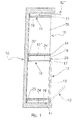
- a cooling rack 10 is shown in horizontal section.
- the cooling shelf 1.0 has for removing the goods on a lying in a vertical opening plane access opening.
- Such a cooling rack is particularly suitable for the storage of goods at a cooling temperature of +0 to +10 degrees Celsius.
- the lying in the cooling rack 10 elongated refrigerator 15 is divided by vertically stacked shelves 36 into individual compartments.
- the cooling rack 10 is divided into two shelf sections, wherein a shelf portion extends approximately the length of a control shelf 36.
- Each shelf section has its own refrigerator 15.
- Door devices 11 are arranged between the inside of the cooling rack side wall 19 and the respective refrigerator compartment 15, so that the refrigerator compartment 10 which is open towards the front is completely closed by a total of four doors 12, 12 ', 12 ", 12'" of the door devices 11, 11 ' can.
- the single cassette 17 has a door 12 and a cassette sidewall 14 disposed between the door 12 and the refrigerator 15.
- the door device 11 ' has a double cassette 17'. In contrast to the single cassette 17, it has two doors 12 in corresponding rails 16, 18, the doors 12 being arranged between two cassette side walls 14.
- FIG. 1 the door device 11 is shown in the use position in the left shelf section.
- the two doors 12 of the left shelf section are in the closed position, in which the doors 12, 12 'are pivotable about their vertical axis.
- Each door 12 has a large glass sheet 13, which is held in a narrow frame, resulting in a good visibility of the goods.
- the door 12 "of the middle door device 11 ' is shown in the parking position and the other door 12"' when entering the parking position.
- the FIG. 2 shows an exploded view of the door device 11 as a single-cassette 17, as shown on the insides of the cooling rack side walls 19 in the FIG. 1 located.
- the single cassette 17 has a frame 20, 22, 24 formed by the arrangement of a horizontal upper frame part 22, a lower horizontal frame part 24 and a vertical connecting part 20. Together with the frame parts 22, 24, the connecting part 20 forms a C-shaped frame 20, 22, 24, whose internal dimensions are chosen so large that the frame 20, 22, 24 completely receives the door 12 and the cassette side wall 14.
- the connecting part 20 also has receptacles for holding webs 32 for the shelves 36.
- the rails 16, 18 are U-shaped, with other embodiments are possible.
- the upper rail 16 is down and the lower rail 18 is open upwards.
- the carriage 28 can be slidably mounted or even roller bearings.
- the carriage 28 of a door device 11 can be coupled with cables, so that the carriage 28 always move synchronously to each other.
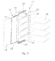
- FIG. 3 also shows an exploded view of a door device 11 'according to the invention, but this has a double cassette 17' and is used for mounting between two shelf sections, as in FIG. 1 shown.
- the single-cassette 17 of FIG. 2 are on the opposite inner sides of the frame members 22 ', 24', the rails 16, 18 made double, so that two doors 12 are parallel to each other in the double cassette 17 'is added.
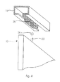
- FIG. 4 shows a detailed view of another advantageous embodiment of the rail.
- the rail 16 is undercut so that there is a nearly C-shaped groove, which ensures an even more stable leadership and a captivity of the carriage 28.
- the door 12 has a vertical bearing pin 30 which is inserted into a vertical bore of the pivot bearing 26 and forms the axis of rotation of the door 12.
Abstract
Description
Die Erfindung betrifft ein Kühlregal mit einem von vorne zugänglichen Kühlraum bzw. eine Türvorrichtung zum Nachrüsten eines derartigen Kühlregals.The invention relates to a refrigerated shelf with a front accessible cooling chamber or a door device for retrofitting such a cooling rack.
Gekühlte Waren werden in Geschäften in Kühlregalen gelagert und präsentiert. Zur Entnahme der Waren weist das Kühlregal eine in einer vertikalen Öffnungsebene liegende Zugriffsöffnung auf, wobei der Kühlraum durch vertikal übereinander angeordnete Regalböden in einzelne getrennte Fächer unterteilt ist. Derartige Kühlregale sind aus dem Stand der Technik hinlänglich bekannt, und zwar sowohl mit nach vorne offenem Kühlraum als auch mit schwenkbaren Türen zur Bildung eines zu allen Seiten geschlossenen Kühlraums, wodurch eine Lagerung der Waren bei weniger +5 Grad Celsius wirtschaftlich möglich ist.Chilled goods are stored and presented in stores in refrigerated shelves. To remove the goods, the refrigerated shelf has a lying in a vertical opening plane access opening, wherein the refrigerator is divided by vertically stacked shelves in individual separate compartments. Such refrigerated shelves are well known in the art, both with the refrigerator open to the front and with hinged doors to form a closed on all sides of the refrigerator, whereby storage of the goods at less +5 degrees Celsius is economically possible.
Bei herkömmlichen Kühlregalen, die zu den Verkaufszeiten offen sind, so dass die Kunden ungehindert an die Waren gelangen, wird die innerhalb des Kühlregals erzeugte Kühlluft durch die Regalrückwand ungerichtet in den Kühlraum geleitet. Ferner strömt ein sogenannter Kaltluftvorhang mit einer relativ hohen Geschwindigkeit in der Zugriffsöffnung des Kühlregals von oben nach unten. Diese gerichtete Kaltluftströmung bildet einen unsichtbaren Vorhang zwischen dem gekühlten Luftvolumen im Kühlraum und der wärmeren Umgebungsluft. Insgesamt weisen derartige Kühlregale hohe Energieverluste auf.In conventional refrigerated shelves, which are open at the time of sale, so that the customers get unhindered to the goods, the cooling air generated within the cooling rack is passed undirected through the shelf back wall in the refrigerator. Further, a so-called cold air curtain flows at a relatively high speed in the access opening of the cooling rack from top to bottom. This directed cold air flow forms an invisible curtain between the cooled air volume in the cold room and the warmer ambient air. Overall, such refrigerated shelves have high energy losses.
Erst außerhalb der Verkaufszeiten wird aus Kosten- und Energiespargründen der offene Kühlraum derartiger Kühlregale mittels entsprechender Nachtabdeckungen verschlossen. Im Regelfall ist die Nachtabdeckung als ein Rollo ausgebildet, das in seiner Nichtgebrauchsposition auf einer im oberen Bereich des Kühlregales angeordneten Rolle aufgewickelt ist. Das Rollo wird manuell oder automatisch am Ende der Verkaufszeiten in eine Abdeckposition gebracht bzw. verfahren, so dass der Kühlraum des Kühlregales gegen die wärmere Umgebungsluft abgeschlossen ist.Only outside the sales hours of cost and energy saving reasons of the open refrigerator such refrigerated shelves means closed corresponding night covers. As a rule, the night cover is designed as a roller blind which, in its non-use position, is wound on a roller arranged in the upper region of the refrigerated shelf. The roller blind is brought or moved manually or automatically at the end of the sale times in a covering position, so that the cooling space of the refrigerated shelves is sealed against the warmer ambient air.
Andere Kühlregale weisen dagegen den Kühlraum verschließende und zum Öffnen um eine Vertikale schwenkbare Türen auf. Im Gegensatz zu den vorne offenen Kühlregalen wird auf diese Weise auch während der Verkaufszeiten Energie eingespart. Die geschlossenen Türen wirken sich allerdings negativ auf die Sichtbarkeit der im Kühlregal befindlichen Waren aus. Ferner muss der Kunde mindestens eine Tür öffnen, um die präsentierte Ware aus dem Kühlregal entnehmen zu können, was zu Stoßzeiten den Umsatz verringern kann.On the other hand, other refrigerated shelves have doors which close the refrigerator compartment and can be swiveled around a vertical opening. In contrast to the open-front refrigerated shelves, this also saves energy during the sales hours. The closed doors, however, have a negative effect on the visibility of the goods in the refrigerated display. Furthermore, the customer has to open at least one door in order to be able to remove the presented goods from the refrigerated shelf, which can reduce turnover at peak times.
Aufgabe der vorliegenden Erfindung ist es, ein Kühlregal bzw. eine Türvorrichtung hierfür zu schaffen, das flexibel und energiesparend betrieben werden kann.Object of the present invention is to provide a cooling rack or a door device for this purpose, which can be operated flexibly and energy-saving.
Die Lösung dieser Aufgabe erfolgt erfindungsgemäß mit den Merkmalen des Patentanspruchs 1 oder 10.The solution of this object is achieved according to the invention with the features of
Das erfindungsgemäße Kühlregal weist eine Türvorrichtung mit zwei Schienen auf, die annähernd parallel zu einer Seitenwand des Kühlregals angeordnet sind. Die Türvorrichtung weist außerdem eine Tür auf, die in zwei Drehlagern um ihre vertikale Achse drehbar gelagert ist, wobei die Drehlager in den zwei Schienen verschiebbar gelagert sind.The refrigerated shelf according to the invention has a door device with two rails, which are arranged approximately parallel to a side wall of the refrigerated shelf. The door device also has a door which is rotatably mounted in two pivot bearings about its vertical axis, wherein the pivot bearings are slidably mounted in the two rails.
Die Tür kann zwischen einer Gebrauchsposition vor dem Kühlraum, in der die Tür zwischen einer Öffnungsstellung und Schließstellung um die vertikale Achse schwenkbar ist, und einer Parkposition neben dem Kühlraum, in der die Tür sich unschwenkbar zwischen den Schienen seitlich des Kühlraums befindet, verschoben werden. Ausgehend von der Öffnungsstellung, lässt sich die Tür in die Tiefe des Kühlregals parallel zur Seite des Kühlraums verschieben. In der Gebrauchsposition ist die Tür in eine Öffnungsstellung schwenkbar, um Ware entnehmen zu können.The door may be displaced between a use position in front of the refrigerated space in which the door is pivotable about the vertical axis between an open position and closed position, and a parking position adjacent to the refrigerated space in which the door is non-pivotally located between the rails laterally of the refrigerated space. Starting from the open position, the door can be moved into the depth of the cooling rack parallel to the side of the cold room. In the use position, the door is pivotable in an open position to remove goods.
Da die Türen in der Gebrauchsposition zu Stoßzeiten bei Kunden verkaufshemmend wirken, was unerwünscht ist, lässt sich die Tür zu diesen Zeiten in eine Parkposition neben dem Kühlraum vollständig und platzsparend verstauen, so dass das Kühlregal nach vorne ständig offen ist und der Kunde ungehindert auf die Ware zugreifen kann.Since the doors in the use position at peak times at customers counteract sales, which is undesirable, the door can be stowed at these times in a parking position next to the refrigerator completely and space-saving, so that the cooling rack forward is always open and the customer unhindered on the Goods can access.
Damit die Tür nicht zufäilig oder durch unbefugten Zugriff z.B. aus der Öffnungsstellung der Gebrauchsposition in die Parkposition und umgekehrt verschoben werden kann, ist die Tür sowohl in der Gebrauchsposition als auch in der Parkposition vorzugsweise verriegelbar ausgeführt.To prevent the door from being accidentally or unauthorized access, e.g. can be moved from the open position of the use position in the parking position and vice versa, the door is designed preferably lockable both in the use position and in the parking position.
Vorzugsweise sind die Schienen der Türvorrichtung als eine Nut ausgebildet, wobei eine vorteilhafte Ausführung z.B. eine U-förmige Nut darstellt. In jeder Schiene kann außerdem ein verschiebbarer Schlitten geführt werden, der die Drehlager der Tür aufweist und verhindert, dass sich die Tür beim Verschieben verkantet. Der Schlitten kann gleitgelagert oder mit einem Wälzlager gelagert sein.Preferably, the rails of the door device are formed as a groove, an advantageous embodiment being e.g. represents a U-shaped groove. In addition, in each rail a sliding carriage can be guided, which has the pivot bearing of the door and prevents the door from tilting when moving. The carriage may be slide-mounted or mounted with a rolling bearing.
In einer bevorzugten Ausführung weist die Türvorrichtung eine Kassette mit einem C-förmigen Rahmen auf. Der Rahmen setzt sich aus einem horizontalen oberen Rahmenteil und einem horizontalen unteren Rahmenteil zusammen, welche über ein vertikales Verbindungsteil miteinander verbunden sind. Das vertikale Verbindungsteil kann gleichzeitig auch Träger der Halterungen der Regelböden sein und ist an der dem Kühlraum zugewandten Seite zwischen den Regalabschnitten an der Regalrückwand befestigt, wobei ein Regalabschnitt der Länge eines Regalbodens entspricht.In a preferred embodiment, the door device comprises a cassette with a C-shaped frame. The frame is composed of a horizontal upper frame part and a horizontal lower frame part, which via a vertical connecting part connected to each other. The vertical connecting part may also be the carrier of the holders of the control shelves and is fastened on the side facing the cooling space between the shelf sections on the shelf rear wall, wherein a shelf section corresponds to the length of a shelf.
Der Rahmen kann zusätzlich eine Seitenwand aufweisen. Die Seitenwand bildet neben der räumlichen Trennung von Regalabschnitten auch einen Schutz vor Verschmutzung und verhindert, dass in der Gebrauchsposition der Tür Waren in die Kassette fallen. Fener stabilisiert die Seitenwand den Rahmen.The frame may additionally have a side wall. The side wall forms in addition to the spatial separation of shelves and a protection against contamination and prevents fall in the use position of the door goods in the cassette. Fener stabilizes the side wall of the frame.
Bei einem langgestreckten Kühlregal, wie
Damit die Tür vollständig in den Rahmen der Kassette eingefahren werden kann, ist es vorteilhaft, dass die Breite der Tür nicht größer als die Tiefe des Kühlregals ist.In order for the door to be completely retracted into the frame of the cassette, it is advantageous that the width of the door is not greater than the depth of the refrigerator shelf.
Die Türvorrichtung weist vorzugsweise einen Selbstschließungsmechanismus auf, durch den die Tür in der Gebrauchsposition bei einem Türöffnungswinkel von bevorzugt kleiner 30° selbsttätig in die Schließstellung bewegt. Befindet sich die Tür in der Gebrauchsposition, in der diese Tür bei Bedarf geöffnet und anschließend wieder geschlossen werden kann, kann es vorkommen, dass der Konsument die Tür nach Entnahme der Ware offen stehen lässt oder die Tür nur "zuwirft", und diese nicht vollständig schließt. Dies führt wiederum zu einem unerwünschten Anstieg des Energieverbrauchs. Der Selbstschließungsmechanismus schließt die Tür zwangsweise.The door device preferably has a self-closing mechanism, by which the door automatically moves into the closed position in the use position at a door opening angle of preferably less than 30 °. If the door is in the use position, in which this door can be opened if necessary and then closed again, it may happen that the consumer leaves the door open after the goods have been removed or only "throws" the door, and not completely closes. This in turn leads to an undesirable increase in energy consumption. The self-closing mechanism closes the door forcibly.
Bei einer zweiten erfindungsgemäßen Lösung ist zum Nachrüsten eines nach vorne offenen Kühlregals eine Türvorrichtung vorgesehen, durch die ein nach vorne offenes Kühlregal vollständig durch Türen verschlossen werden kann.In a second solution according to the invention a door device is provided for retrofitting a forwardly open cooling rack, through which a forwardly open cooling rack can be completely closed by doors.
Für herkömmliche, insbesondere für offene Kühlregale ist damit eine Möglichkeit geschaffen, nachträglich eine Türvorrichtung zu installieren, die Energieeinsparrung und bei Bedarf leichte Zugänglichkeit gewährleistet.For conventional, especially for open cooling shelves, this creates a possibility to subsequently install a door device that ensures energy saving and, if necessary, easy accessibility.
Im Folgenden wird unter Bezugnahme auf die Zeichnungen ein Ausführungsbeispiel der Erfindung näher erläutert.In the following an embodiment of the invention will be explained in more detail with reference to the drawings.
Es zeigen :
- Figur 1
- einen Querschnitt eines Kühlregals mit nachgerüsteten Türvorrichtungen,
- Figur 2
- eine Explosionsdarstellung einer Türvorrichtung in einfacher Ausführung für die linke Seite des Kühlregals der
Figur 1 , - Figur 3
- eine Expiosionsdsrstellung einer Türvorrichtung in doppelter Ausführung für die Montage zwischen zwei Regalabschnitten des Kühlregals der
Figur 1 , und - Figur 4
- eine Detailansicht der Lagerung des Schlitten in der oberen Schiene.
- FIG. 1
- a cross section of a refrigerated shelf with retrofitted door devices,
- FIG. 2
- an exploded view of a door device in a simple design for the left side of the cooling rack of
FIG. 1 . - FIG. 3
- an Expionsionsstellrstellung a door device in duplicate for mounting between two shelves of the cooling rack of the
FIG. 1 , and - FIG. 4
- a detailed view of the storage of the carriage in the upper rail.
In der
Durch die mittige Anbringung eine Türvorrichtung 11' an der Regalrückwand des Kühlregals 10, wird das Kühlregal 10 in zwei Regalabschnitte unterteilt, wobei ein Regalabschnitt sich ungefähr über die Länge eines Regelbodens 36 erstreckt. Jeder Regalabschnitt weist einen eigenen Kühlraum 15 auf. Zwischen der Innenseite der Kühlregal-Seitenwand 19 und dem jeweiligen Kühlraum 15 sind Türvorrichtungen 11 angeordnet, so dass das nach vorne offene Kühlregal 10 vollständig durch insgesamt vier Türen 12, 12', 12", 12'" der Türvorrichtungen 11, 11' geschlossen werden kann.By the central attachment a door device 11 'on the shelf rear wall of the
Je nach Länge eines Kühlregals 10 können auch weitere Türvorrichtungen 11' an der Regalrückwand befestigt werden, so dass mehr als die zwei Regalabschnitte der beispielhaften Ausführungsform in
Die Türvorrichtungen 11, die an der Innenseite der Kühlregal-Seitenwand 19 angeordnet sind, weisen an der dem Kühlraum 15 zugewandten Seite eine Einfach-Kassette 17 auf. Die Einfach-Kassette 17 weist eine Tür 12 und eine Kassetten-Seitenwand 14 auf, die zwischen der Tür 12 und dem Kühlraum 15 angeordnet ist.The
Die Türvorrichtung 11' weist eine Doppel-Kassette 17' auf. Sie weist im Gegensatz zur Einfach-Kassette 17 zwei Türen 12 in entsprechenden Schienen 16, 18 auf, wobei die Türen 12 zwischen zwei Kassetten-Seitenwänden 14 angeordnet sind.The door device 11 'has a double cassette 17'. In contrast to the
In
Die
Das Verbindungsteil 20 weist ferner Aufnahmen für Haltestege 32 für die Regalböden 36 auf.The connecting
An den sich gegenüberliegenden Innenseiten der Rahmenteile 22, 24 befinden sich Schienen 16, 18, in denen ein Schlitten 28 verschiebbar gelagert ist. Der Schlitten 28 nimmt die Tür 12 über ein Drehlager 26 auf, so dass die Tür in der Gebrauchsposition zusätzlich drehbar gelagert ist.On the opposite inner sides of the
Zur Führung des Schlittens 28 sind die Schienen 16, 18 U-förmig ausgebildet, wobei auch andere Ausführungsformen möglich sind. In dem Ausführungsbeispiel in
Die
Die
Claims (11)
wobei die Türvorrichtung (11) eine Tür (12) aufweist, die in zwei Drehlagern (26) um eine vertikale Achse drehbar zwischen einer Schließstellung und einer Öffnungsstellung gelagert ist,
dadurch gekennzeichnet,
dass die Türvorrichtung (11) zwei Schienen (16, 18) aufweist, die annähernd parallel zu einer Seitenwand (14) des Kühlregals (10) angeordnet sind und in denen die Drehlager (26) der Tür (12) verschiebbar gelagert sind,
so dass die Tür (12) in den Schienen (16, 18) zwischen einer Gebrauchsposition vor dem Kühlraum (15), in der die Tür (12) zwischen der Öffnungsstellung und Schließstellung schwenkbar ist, und einer Parkposition neben dem Kühlraum (15), in der die Tür (12) unschwenkbar ist, verschiebbar ist.Cooling shelf (10) with a cooling chamber (15) closing door device (11),
wherein the door device (11) has a door (12) which is mounted in two pivot bearings (26) rotatable about a vertical axis between a closed position and an open position,
characterized,
in that the door device (11) has two rails (16, 18) which are arranged approximately parallel to a side wall (14) of the cooling rack (10) and in which the pivot bearings (26) of the door (12) are displaceably mounted,
such that the door (12) in the rails (16, 18) between a use position in front of the cooling space (15), in which the door (12) is pivotable between the open position and closed position, and a parking position adjacent to the cooling space (15), in which the door (12) is pivotable, is displaceable.
annähernd parallel zu einer Seitenwand (14) des Kühlregals (10) angeordnet sind und in denen die Drehlager (26) der Tür (12) verschiebbar gelagert sind, so dass die Tür (12) in den Schienen (16, 18) zwischen einer Gebrauchsposition vor dem Kühlraum (15), in der die Tür (12) zwischen der Öffnungsstellung und Schließstellung schwenkbar ist, und einer Parkposition neben dem Kühlraum (15), in der die Tür (12) unschwenkbar ist, verschiebbar ist.Door device (11) for retrofitting a front open cooling rack according to the preamble of claim 1, characterized in that the door device (11) has two rails (16, 18) which
are arranged approximately parallel to a side wall (14) of the cooling rack (10) and in which the pivot bearing (26) of the door (12) are slidably mounted, so that the door (12) in the rails (16, 18) between a position of use in front of the cooling space (15), in which the door (12) is pivotable between the open position and the closed position, and a parking position next to the cooling space (15), in which the door (12) is pivotable, is displaceable.
Applications Claiming Priority (1)
| Application Number | Priority Date | Filing Date | Title |
|---|---|---|---|
| DE102010004950A DE102010004950A1 (en) | 2010-01-18 | 2010-01-18 | Cooling shelf with door device |
Publications (2)
| Publication Number | Publication Date |
|---|---|
| EP2345347A1 true EP2345347A1 (en) | 2011-07-20 |
| EP2345347B1 EP2345347B1 (en) | 2016-03-30 |
Family
ID=43805675
Family Applications (1)
| Application Number | Title | Priority Date | Filing Date |
|---|---|---|---|
| EP10194383.5A Not-in-force EP2345347B1 (en) | 2010-01-18 | 2010-12-09 | Refrigerated cabinet with door assembly |
Country Status (3)
| Country | Link |
|---|---|
| US (1) | US8500224B2 (en) |
| EP (1) | EP2345347B1 (en) |
| DE (1) | DE102010004950A1 (en) |
Cited By (5)
| Publication number | Priority date | Publication date | Assignee | Title |
|---|---|---|---|---|
| DE202012001984U1 (en) | 2012-02-16 | 2012-06-12 | Schott Ag | refrigeration cabinets |
| DE102012202392A1 (en) | 2012-02-16 | 2013-08-22 | Schott Ag | refrigeration cabinets |
| EP2907951A1 (en) | 2014-02-14 | 2015-08-19 | REMIS Gesellschaft für Entwicklung und Vertrieb von technischen Elementen mbH Köln | Commercial refrigerated shelf |
| WO2018129569A1 (en) * | 2017-01-13 | 2018-07-19 | Julius Blum Gmbh | Guide system for a door assembly, door assembly, and device assembly |
| EP3585216B1 (en) * | 2017-02-24 | 2023-06-07 | Carrier Corporation | Refrigerated sales furniture |
Families Citing this family (9)
| Publication number | Priority date | Publication date | Assignee | Title |
|---|---|---|---|---|
| US8556321B2 (en) * | 2011-02-17 | 2013-10-15 | Johnson Truck Bodies, LLC | Refrigerated trailer door having an automotive-style handle and locking mechanism |
| ITRM20110243A1 (en) * | 2011-05-19 | 2012-11-20 | Ind Scaffalature Arredamenti Isa S R L | REFRIGERATOR EXHIBITOR. |
| DE202011052121U1 (en) | 2011-11-28 | 2012-01-31 | Dusar Bath & Wellness Gmbh & Co. Kg | Cooling shelf with sliding door arrangement |
| US9372025B2 (en) | 2012-10-22 | 2016-06-21 | Anthony, Inc. | Covers for refrigeration systems |
| CN107009948A (en) * | 2017-03-09 | 2017-08-04 | 华晨专用车装备科技(大连)有限公司 | Refrigerator car separates door system |
| CN110464168B (en) | 2018-05-10 | 2023-10-20 | 开利公司 | Refrigeration showcase and control method thereof |
| US11035576B2 (en) | 2019-06-25 | 2021-06-15 | Bsh Home Appliances Corporation | Cooking appliance with side opening retractable door |
| US11149485B2 (en) | 2019-06-25 | 2021-10-19 | Bsh Home Appliances Corporation | Cooking appliance having stowable double doors |
| CN114016843B (en) * | 2021-11-10 | 2023-04-18 | 郑州轻工业大学 | Cabin door replacing method and replaceable cabin door system |
Citations (8)
| Publication number | Priority date | Publication date | Assignee | Title |
|---|---|---|---|---|
| JPS4896548U (en) * | 1972-02-17 | 1973-11-16 | ||
| JPS5081100A (en) * | 1973-11-14 | 1975-07-01 | ||
| NL7806193A (en) * | 1977-06-30 | 1979-01-03 | Telefonbau & Normalzeit Gmbh | APPLIANCE CABINET. |
| JPS541259U (en) * | 1977-06-06 | 1979-01-06 | ||
| JPS55121181U (en) * | 1979-02-21 | 1980-08-28 | ||
| US4341083A (en) * | 1980-05-01 | 1982-07-27 | Tyler Refrigeration Corporation | Door operating mechanism for refrigerated merchandiser display cabinet |
| JPH0367979A (en) * | 1989-08-03 | 1991-03-22 | Sanyo Electric Co Ltd | Container |
| US5121976A (en) * | 1989-03-14 | 1992-06-16 | Karl Haab | Furniture article with a door slidable into door compartment |
Family Cites Families (96)
| Publication number | Priority date | Publication date | Assignee | Title |
|---|---|---|---|---|
| US2153143A (en) * | 1938-01-28 | 1939-04-04 | Eastman Kodak Co | Nondiscoloring, liquid antiseptic soap |
| US2669499A (en) * | 1949-10-20 | 1954-02-16 | Vanderplank Hugh | Door mounting for structures, including cupboards |
| US2678902A (en) * | 1950-11-06 | 1954-05-18 | Colgate Palmolive Co | Hand lotion |
| US2936206A (en) * | 1958-06-17 | 1960-05-10 | Gen Fireproofing Co | Sliding doors for cabinets |
| US3017233A (en) * | 1959-05-21 | 1962-01-16 | Servco Equipment Company | Counters and sliding closures therefor |
| US3131152A (en) * | 1960-06-13 | 1964-04-28 | Allied Chem | Foam producing formulations |
| US3131154A (en) * | 1961-10-25 | 1964-04-28 | Allied Chem | Foam producing compositions |
| US3824303A (en) * | 1963-07-24 | 1974-07-16 | Yardley Of London Inc | Collapsible foam pre-electric shave lotion containing diester lubricants |
| US3395214A (en) * | 1964-01-09 | 1968-07-30 | Scholl Mfg Co Inc | Antiperspirant composition providing a readily collapsible sprayable foam |
| US3709437A (en) * | 1968-09-23 | 1973-01-09 | Hershel Earl Wright | Method and device for producing foam |
| US3962150A (en) * | 1974-04-10 | 1976-06-08 | Richardson-Merrell Inc. | Foam producing cleansing compositions |
| US4006218A (en) * | 1974-07-08 | 1977-02-01 | Johnson & Johnson | Potentiated medicaments |
| JPS5729213B2 (en) * | 1974-11-12 | 1982-06-21 | ||
| US4202881A (en) * | 1976-06-18 | 1980-05-13 | Wella Ag | Hair shampoo and conditioning lotion |
| US4199564A (en) * | 1978-09-22 | 1980-04-22 | Masti-Kure Products Company, Inc. | Film-forming alcoholic microbicidal teat dip and method of use thereof |
| US4666896A (en) * | 1979-04-26 | 1987-05-19 | Bristol-Myers Company | Chlorhexidine salts and compositions of same |
| US4311695A (en) * | 1979-12-03 | 1982-01-19 | Dow Corning Corporation | Personal-care emulsions comprising a siloxane-oxyalkylene copolymer |
| US4511486A (en) * | 1981-11-02 | 1985-04-16 | Richardson-Vicks Inc. | Method of cleaning dentures using aerated foams |
| US4440653A (en) * | 1982-03-08 | 1984-04-03 | Halliburton Company | Highly stable alcohol foams and methods of forming and using such foams |
| US4464293A (en) * | 1982-04-12 | 1984-08-07 | Dobrin Robert J | Liquid cleaner-disinfectant composition for use in wiping down dental operatories |
| US4454060A (en) * | 1983-06-09 | 1984-06-12 | Colgate-Palmolive Company | Liquid detergent composition with a cationic foam stabilizing copolymer containing pendant quaternary nitrogen groups and pendant hydrophobic groups |
| US4752612A (en) * | 1983-07-01 | 1988-06-21 | Nitto Electrical Industrial Co., Ltd. | Method and percutaneously administering physiologically active agents using an alcohol adjuvant and a solvent |
| WO1985001876A1 (en) * | 1983-10-24 | 1985-05-09 | Lockley Services Pty. Ltd. | Foamable biocide composition |
| US4501834A (en) * | 1983-12-22 | 1985-02-26 | Colgate-Palmolive Company | Gels formed from anionic and cationic polymers |
| JPS60107265U (en) * | 1983-12-26 | 1985-07-22 | 有限会社 東京巧作所 | Door storage structure |
| DE3406497A1 (en) * | 1984-02-23 | 1985-09-05 | Mueller Bernhard Willi Werner | HIGHLY DISPERSAL PHARMACEUTICAL MULTI-COMPONENT SYSTEMS AND METHOD FOR THEIR PRODUCTION |
| US4584192A (en) * | 1984-06-04 | 1986-04-22 | Minnesota Mining & Manufacturing Company | Film-forming composition containing an antimicrobial agent and methods of use |
| IL77224A (en) * | 1984-12-12 | 1989-09-10 | Euro Celtique Sa | Antibacterial cream |
| US4567038A (en) * | 1985-03-06 | 1986-01-28 | Revlon, Inc. | Sunscreen composition for hair protection |
| US4826828A (en) * | 1985-04-22 | 1989-05-02 | Avon Products, Inc. | Composition and method for reducing wrinkles |
| US4806262A (en) * | 1985-08-14 | 1989-02-21 | The Procter & Gamble Company | Nonlathering cleansing mousse with skin conditioning benefits |
| US4683004A (en) * | 1985-08-20 | 1987-07-28 | Union Carbide Corporation | Foamable compositions and processes for use thereof |
| US5288486A (en) * | 1985-10-28 | 1994-02-22 | Calgon Corporation | Alcohol-based antimicrobial compositions |
| LU86429A1 (en) * | 1986-05-16 | 1987-12-16 | Oreal | COSMETIC COMPOSITIONS CONTAINING A CATIONIC POLYMER AND AN ANIONIC POLYMER AS A THICKENING AGENT |
| US4831023A (en) * | 1986-06-27 | 1989-05-16 | Thames Pharmacal Co., Inc. | Water washable vehicles for topical use |
| US4857302A (en) * | 1987-02-20 | 1989-08-15 | Decker Jr Donald F | Solubilized benzoyl peroxide and cosmetic solution including solubilized benzoyl peroxide |
| AU611421B2 (en) * | 1987-02-23 | 1991-06-13 | Shiseido Company Ltd. | Percutaneous absorption promoter and dermatologic preparation for external use |
| US4906459A (en) * | 1987-10-23 | 1990-03-06 | The Procter & Gamble Company | Hair care compositions |
| US4931282A (en) * | 1987-11-25 | 1990-06-05 | Minnesota Mining And Manufacturing Company | Pressure-sensitive medical sealant |
| US5225473A (en) * | 1987-11-25 | 1993-07-06 | Minnesota Mining And Manufacturing Company | Pressure-sensitive adhesives |
| US5223261A (en) * | 1988-02-26 | 1993-06-29 | Riker Laboratories, Inc. | Transdermal estradiol delivery system |
| US4897262A (en) * | 1988-03-22 | 1990-01-30 | Playtex Jhirmack, Inc. | Non-aerosol hair spray composition |
| US5298182A (en) * | 1989-01-31 | 1994-03-29 | Ciba-Geigy Corporation | Rapid ophthalmic glycol/lower alkanol cleaning and disinfecting solution and method |
| US5232691A (en) * | 1989-04-26 | 1993-08-03 | Lemole Gerald M | Protective gel composition |
| US5100658A (en) * | 1989-08-07 | 1992-03-31 | The Procter & Gamble Company | Vehicle systems for use in cosmetic compositions |
| US5104646A (en) * | 1989-08-07 | 1992-04-14 | The Procter & Gamble Company | Vehicle systems for use in cosmetic compositions |
| US5290555A (en) * | 1989-09-14 | 1994-03-01 | Revlon Consumer Products Corporation | Cosmetic compositions with structural color |
| US4983377A (en) * | 1989-10-31 | 1991-01-08 | The Procter & Gamble Company | Silicone hairspray compositions |
| FR2657617B1 (en) * | 1990-01-31 | 1994-03-25 | Oreal | OIL-IN-WATER EMULSIONS BASED ON INSOLUBLE SILICONES AND AN EMULSIFYING AGENT OF THE CARBOXYLIC ACID POLYOXYALKYLENE ACID TYPE, AND THEIR APPLICATION IN COSMETICS AND DERMATOLOGY. |
| FR2658076B1 (en) * | 1990-02-12 | 1992-06-12 | Sanofi Sa | COSMETIC COMPOSITION CONTAINING COPOLYMERS OF AMINO ACIDS, USEFUL AS A MOISTURIZING AGENT. |
| DE20308057U1 (en) * | 2003-05-21 | 2004-07-22 | Heinrich J. Kesseböhmer KG | Pull-out device for cabinet extensions, especially in a tall cabinet |
| US5108165A (en) * | 1990-06-12 | 1992-04-28 | Westinghouse Electric Corp. | Flush-front cabinet door and hinge therefor |
| US5128123A (en) * | 1991-02-08 | 1992-07-07 | Chesebrough-Pond's Usa Co., Division Of Conopco, Inc. | Clear cosmetic sticks |
| US5284486A (en) * | 1991-06-11 | 1994-02-08 | Microvena Corporation | Self-centering mechanical medical device |
| FR2677982B1 (en) * | 1991-06-24 | 1993-09-24 | Oreal | POLYFLUOROALKYLTHIOPOLY (ETHYLIMIDAZOLIUM) COMPOUNDS, PROCESS FOR THE PREPARATION THEREOF AND THEIR USE AS BIOCIDAL AGENTS. |
| CA2074293C (en) * | 1991-07-25 | 2002-03-19 | John R. Horoschak | Water-based hair fixative composition |
| GB9118979D0 (en) * | 1991-09-04 | 1991-10-23 | Unilever Plc | Cosmetic composition |
| US5180061A (en) * | 1991-09-09 | 1993-01-19 | Becton, Dickinson And Company | Stable iodophor in polyurethane foam |
| US5276079A (en) * | 1991-11-15 | 1994-01-04 | Minnesota Mining And Manufacturing Company | Pressure-sensitive poly(n-vinyl lactam) adhesive composition and method for producing and using same |
| US5494533A (en) * | 1991-12-12 | 1996-02-27 | Richardson-Vicks, Inc. | Method for personal cleansing |
| JPH07506367A (en) * | 1992-05-05 | 1995-07-13 | ザ、プロクター、エンド、ギャンブル、カンパニー | acne treatment composition |
| US5635469A (en) * | 1993-06-10 | 1997-06-03 | The Procter & Gamble Company | Foaming cleansing products |
| US5484597A (en) * | 1993-07-30 | 1996-01-16 | Chesebrough-Pond's Usa Co. | Clear hydroalcholic cosmetic microemulsions |
| US5512199A (en) * | 1993-11-02 | 1996-04-30 | Becton Dickinson And Company | Hand wipe solution |
| IT1265001B1 (en) * | 1993-12-16 | 1996-10-17 | Zambon Spa | PHARMACEUTICAL COMPOSITION FOR TOPICAL USE CONTAINING (S) -2- (4- ISOBUTYLPHENYL) PROPIONIC ACID |
| FR2717075B1 (en) * | 1994-03-14 | 1996-04-05 | Oreal | Aqueous organopolysiloxane makeup gel. |
| US6086856A (en) * | 1994-03-28 | 2000-07-11 | Oralcare Systems, Inc. | System for delivering foamed oral hygiene compositions |
| CA2151774C (en) * | 1994-06-27 | 1999-04-06 | Minh Quang Hoang | Skin disinfecting formulations |
| DE4435932C2 (en) * | 1994-10-07 | 1997-08-21 | Convotherm Elektrogeraete | Cooking appliance with a door closing a front opening |
| US5776430A (en) * | 1994-11-01 | 1998-07-07 | Calgon Vestal, Inc. | Topical antimicrobial cleanser containing chlorhexidine gluconate and alcohol |
| WO1996016650A1 (en) * | 1994-11-29 | 1996-06-06 | Hisamitsu Pharmaceutical Co., Inc. | Antibacterial or bactericide comprising 2-aminothiazole derivative and salts thereof |
| FI98290C (en) * | 1995-02-08 | 1997-05-26 | Kvaerner Masa Yards Oy | Water equalization arrangement |
| US7566460B2 (en) * | 1995-06-22 | 2009-07-28 | 3M Innovative Properties Company | Stable hydroalcoholic compositions |
| JP4497559B2 (en) * | 1995-06-22 | 2010-07-07 | スリーエム カンパニー | Stable hydroalcohol composition |
| US6623744B2 (en) * | 1995-06-22 | 2003-09-23 | 3M Innovative Properties Company | Stable hydroalcoholic compositions |
| CA2224798A1 (en) * | 1995-06-22 | 1997-01-09 | Matthew T. Scholz | Stable hydroalcoholic compositions |
| US5733535A (en) * | 1995-10-25 | 1998-03-31 | The Procter & Gamble Co. | Topical compositions containing N-acetylcysteine and odor masking materials |
| US5897031A (en) * | 1996-06-21 | 1999-04-27 | Minnesota Mining And Manufacturing Company | Dispenser for antimicrobial liquids |
| US5765263A (en) * | 1996-07-15 | 1998-06-16 | Southco, Inc. | Door positioning hinge |
| US5756077A (en) * | 1996-09-13 | 1998-05-26 | Avlon Industries, Inc. | Hair protectant composition and process for preserving chemically processed hair during subsequent chemical processing |
| US6019997A (en) * | 1997-01-09 | 2000-02-01 | Minnesota Mining And Manufacturing | Hydroalcoholic compositions for transdermal penetration of pharmaceutical agents |
| US6582711B1 (en) * | 1997-01-09 | 2003-06-24 | 3M Innovative Properties Company | Hydroalcoholic compositions thickened using polymers |
| US5908619A (en) * | 1997-01-09 | 1999-06-01 | Minnesota Mining And Manufacturing Company | Hydroalcoholic compositions thickened using surfactant/polymer complexes |
| US6056376A (en) * | 1998-10-21 | 2000-05-02 | Streater, Inc. | Display case |
| US6183766B1 (en) * | 1999-02-12 | 2001-02-06 | The Procter & Gamble Company | Skin sanitizing compositions |
| US6423329B1 (en) * | 1999-02-12 | 2002-07-23 | The Procter & Gamble Company | Skin sanitizing compositions |
| US20020040046A1 (en) * | 1999-03-31 | 2002-04-04 | Patel Jitendra P | Novel formulations comprising lipid-regulating agents |
| KR100596533B1 (en) * | 1999-09-04 | 2006-07-06 | 삼성전자주식회사 | Door handle device of refrigerator |
| ITMC20010017U1 (en) * | 2001-03-29 | 2002-09-30 | Compagnucci Spa | EXTRACTABLE RACK FOR FURNITURE EQUIPPED WITH A SUPPORTING CARTER FOR THE PROTECTION OF THE SLIDING GUIDES. |
| US6383997B1 (en) * | 2001-07-02 | 2002-05-07 | Dragoco Gerberding & Co. Ag | High lathering antibacterial formulation |
| DE10147186A1 (en) * | 2001-09-25 | 2003-04-24 | Beiersdorf Ag | Synergistic antimicrobial composition, useful e.g. as cosmetic preservative and for treating skin disorders, comprises polyhexamethylene biguanide and distearyldimethylammonium chloride |
| US7959242B2 (en) * | 2003-06-02 | 2011-06-14 | Accuride International Inc. | Pocket door cabinet and slide assembly |
| US6848758B1 (en) * | 2003-10-31 | 2005-02-01 | Chih-Cheng Yeh | Do it yourself (DIY) modular cabinet |
| US7651990B2 (en) * | 2005-06-13 | 2010-01-26 | 3M Innovative Properties Company | Foamable alcohol compositions comprising alcohol and a silicone surfactant, systems and methods of use |
| US20070148101A1 (en) * | 2005-12-28 | 2007-06-28 | Marcia Snyder | Foamable alcoholic composition |
| US20070159037A1 (en) * | 2006-01-10 | 2007-07-12 | Knape & Vogt Manufacturing Company | Hinge bracket for a pocket door |
-
2010
- 2010-01-18 DE DE102010004950A patent/DE102010004950A1/en not_active Withdrawn
- 2010-12-09 EP EP10194383.5A patent/EP2345347B1/en not_active Not-in-force
-
2011
- 2011-01-14 US US13/006,582 patent/US8500224B2/en active Active
Patent Citations (8)
| Publication number | Priority date | Publication date | Assignee | Title |
|---|---|---|---|---|
| JPS4896548U (en) * | 1972-02-17 | 1973-11-16 | ||
| JPS5081100A (en) * | 1973-11-14 | 1975-07-01 | ||
| JPS541259U (en) * | 1977-06-06 | 1979-01-06 | ||
| NL7806193A (en) * | 1977-06-30 | 1979-01-03 | Telefonbau & Normalzeit Gmbh | APPLIANCE CABINET. |
| JPS55121181U (en) * | 1979-02-21 | 1980-08-28 | ||
| US4341083A (en) * | 1980-05-01 | 1982-07-27 | Tyler Refrigeration Corporation | Door operating mechanism for refrigerated merchandiser display cabinet |
| US5121976A (en) * | 1989-03-14 | 1992-06-16 | Karl Haab | Furniture article with a door slidable into door compartment |
| JPH0367979A (en) * | 1989-08-03 | 1991-03-22 | Sanyo Electric Co Ltd | Container |
Cited By (12)
| Publication number | Priority date | Publication date | Assignee | Title |
|---|---|---|---|---|
| DE202012001984U1 (en) | 2012-02-16 | 2012-06-12 | Schott Ag | refrigeration cabinets |
| DE102012202392A1 (en) | 2012-02-16 | 2013-08-22 | Schott Ag | refrigeration cabinets |
| WO2013120941A1 (en) | 2012-02-16 | 2013-08-22 | Schott Ag | Refrigeration cabinet |
| DE102012202392B4 (en) * | 2012-02-16 | 2015-08-27 | Schott Ag | refrigeration cabinets |
| EP2814360B1 (en) * | 2012-02-16 | 2018-09-19 | Schott AG | Refrigeration cabinet |
| US10238219B2 (en) | 2012-02-16 | 2019-03-26 | Schott Ag | Refrigeration cabinet |
| EP2907951A1 (en) | 2014-02-14 | 2015-08-19 | REMIS Gesellschaft für Entwicklung und Vertrieb von technischen Elementen mbH Köln | Commercial refrigerated shelf |
| WO2018129569A1 (en) * | 2017-01-13 | 2018-07-19 | Julius Blum Gmbh | Guide system for a door assembly, door assembly, and device assembly |
| TWI676730B (en) * | 2017-01-13 | 2019-11-11 | 奧地利商朱利葉斯百隆股份有限公司 | Guide system for a door arrangement as well as door arrangement and furnishing arrangement |
| EP4134507A1 (en) * | 2017-01-13 | 2023-02-15 | Julius Blum GmbH | Guide system for a door assembly, and door assembly and device assembly |
| US11585136B2 (en) | 2017-01-13 | 2023-02-21 | Julius Blum Gmbh | Guide system for a door assembly, door assembly, and device assembly |
| EP3585216B1 (en) * | 2017-02-24 | 2023-06-07 | Carrier Corporation | Refrigerated sales furniture |
Also Published As
| Publication number | Publication date |
|---|---|
| US8500224B2 (en) | 2013-08-06 |
| EP2345347B1 (en) | 2016-03-30 |
| US20110175509A1 (en) | 2011-07-21 |
| DE102010004950A1 (en) | 2011-07-21 |
Similar Documents
| Publication | Publication Date | Title |
|---|---|---|
| EP2345347B1 (en) | Refrigerated cabinet with door assembly | |
| EP2142050B1 (en) | Device for exhibiting objects | |
| EP3066959B1 (en) | Drawer, piece of furniture with drawer and method for opening a drawer | |
| EP3500133A1 (en) | Drawer rack for a cabinet | |
| DE202018103969U1 (en) | Telescopically extendable and retractable installation module and a cabinet with at least one such installation module | |
| EP2907951B1 (en) | Commercial refrigerated shelf | |
| DE10230508A1 (en) | Refrigeration appliance has door which may be withdrawn horizontally and various goods storage features are installed on rear face | |
| DE202011052121U1 (en) | Cooling shelf with sliding door arrangement | |
| EP0484932B1 (en) | Shower partition | |
| EP2218994B1 (en) | Cooling apparatus with pull-out shelves and underlying supports | |
| DE202008000352U1 (en) | Sales refrigerated furniture with closing device | |
| DE202014011057U1 (en) | Showcase for the display of objects | |
| DE102008040609A1 (en) | Cooling device i.e. household cooling device, for cooling and/or freezing foods, has door having degree of freedom in addition to translation degree of freedom, and trays having degree of freedom in addition to translation degree of freedom | |
| DE202008015580U1 (en) | Piece of furniture with a recording room for a flat screen | |
| EP1974632B1 (en) | Fitting for a cupboard with a front frame installed on the inside of the door of the cupboard | |
| DE202012002884U1 (en) | damper system | |
| DE102015005666A1 (en) | Door arrangement for refrigerated display case | |
| DE202015003240U1 (en) | Door arrangement for refrigerated display case | |
| DE19710775B4 (en) | shower enclosure | |
| DE10106637C2 (en) | Cupboard, esp. Wall cupboard for kitchens | |
| DE19716043A1 (en) | Safe for fire, water, theft protection of EDV plants, data carriers | |
| EP1449999A1 (en) | Swinging door | |
| DE3503733A1 (en) | Show cabinet | |
| DE202015002628U1 (en) | Door arrangement and refrigerated cabinets | |
| EP2895032B1 (en) | Refrigerated goods presentation and sales cabinet |
Legal Events
| Date | Code | Title | Description |
|---|---|---|---|
| PUAI | Public reference made under article 153(3) epc to a published international application that has entered the european phase |
Free format text: ORIGINAL CODE: 0009012 |
|
| AK | Designated contracting states |
Kind code of ref document: A1 Designated state(s): AL AT BE BG CH CY CZ DE DK EE ES FI FR GB GR HR HU IE IS IT LI LT LU LV MC MK MT NL NO PL PT RO RS SE SI SK SM TR |
|
| AX | Request for extension of the european patent |
Extension state: BA ME |
|
| 17P | Request for examination filed |
Effective date: 20111026 |
|
| 17Q | First examination report despatched |
Effective date: 20121203 |
|
| GRAP | Despatch of communication of intention to grant a patent |
Free format text: ORIGINAL CODE: EPIDOSNIGR1 |
|
| INTG | Intention to grant announced |
Effective date: 20151014 |
|
| RAP1 | Party data changed (applicant data changed or rights of an application transferred) |
Owner name: REMIS GESELLSCHAFT FUER ENTWICKLUNG UND VERTRIEB T |
|
| GRAS | Grant fee paid |
Free format text: ORIGINAL CODE: EPIDOSNIGR3 |
|
| GRAA | (expected) grant |
Free format text: ORIGINAL CODE: 0009210 |
|
| AK | Designated contracting states |
Kind code of ref document: B1 Designated state(s): AL AT BE BG CH CY CZ DE DK EE ES FI FR GB GR HR HU IE IS IT LI LT LU LV MC MK MT NL NO PL PT RO RS SE SI SK SM TR |
|
| REG | Reference to a national code |
Ref country code: GB Ref legal event code: FG4D Free format text: NOT ENGLISH |
|
| REG | Reference to a national code |
Ref country code: CH Ref legal event code: EP |
|
| REG | Reference to a national code |
Ref country code: AT Ref legal event code: REF Ref document number: 784362 Country of ref document: AT Kind code of ref document: T Effective date: 20160415 |
|
| REG | Reference to a national code |
Ref country code: IE Ref legal event code: FG4D Free format text: LANGUAGE OF EP DOCUMENT: GERMAN |
|
| REG | Reference to a national code |
Ref country code: DE Ref legal event code: R096 Ref document number: 502010011319 Country of ref document: DE |
|
| REG | Reference to a national code |
Ref country code: LT Ref legal event code: MG4D |
|
| PG25 | Lapsed in a contracting state [announced via postgrant information from national office to epo] |
Ref country code: NO Free format text: LAPSE BECAUSE OF FAILURE TO SUBMIT A TRANSLATION OF THE DESCRIPTION OR TO PAY THE FEE WITHIN THE PRESCRIBED TIME-LIMIT Effective date: 20160630 Ref country code: GR Free format text: LAPSE BECAUSE OF FAILURE TO SUBMIT A TRANSLATION OF THE DESCRIPTION OR TO PAY THE FEE WITHIN THE PRESCRIBED TIME-LIMIT Effective date: 20160701 Ref country code: HR Free format text: LAPSE BECAUSE OF FAILURE TO SUBMIT A TRANSLATION OF THE DESCRIPTION OR TO PAY THE FEE WITHIN THE PRESCRIBED TIME-LIMIT Effective date: 20160330 Ref country code: FI Free format text: LAPSE BECAUSE OF FAILURE TO SUBMIT A TRANSLATION OF THE DESCRIPTION OR TO PAY THE FEE WITHIN THE PRESCRIBED TIME-LIMIT Effective date: 20160330 |
|
| REG | Reference to a national code |
Ref country code: NL Ref legal event code: MP Effective date: 20160330 |
|
| PG25 | Lapsed in a contracting state [announced via postgrant information from national office to epo] |
Ref country code: RS Free format text: LAPSE BECAUSE OF FAILURE TO SUBMIT A TRANSLATION OF THE DESCRIPTION OR TO PAY THE FEE WITHIN THE PRESCRIBED TIME-LIMIT Effective date: 20160330 Ref country code: LT Free format text: LAPSE BECAUSE OF FAILURE TO SUBMIT A TRANSLATION OF THE DESCRIPTION OR TO PAY THE FEE WITHIN THE PRESCRIBED TIME-LIMIT Effective date: 20160330 Ref country code: SE Free format text: LAPSE BECAUSE OF FAILURE TO SUBMIT A TRANSLATION OF THE DESCRIPTION OR TO PAY THE FEE WITHIN THE PRESCRIBED TIME-LIMIT Effective date: 20160330 Ref country code: LV Free format text: LAPSE BECAUSE OF FAILURE TO SUBMIT A TRANSLATION OF THE DESCRIPTION OR TO PAY THE FEE WITHIN THE PRESCRIBED TIME-LIMIT Effective date: 20160330 |
|
| PG25 | Lapsed in a contracting state [announced via postgrant information from national office to epo] |
Ref country code: NL Free format text: LAPSE BECAUSE OF FAILURE TO SUBMIT A TRANSLATION OF THE DESCRIPTION OR TO PAY THE FEE WITHIN THE PRESCRIBED TIME-LIMIT Effective date: 20160330 |
|
| PG25 | Lapsed in a contracting state [announced via postgrant information from national office to epo] |
Ref country code: IS Free format text: LAPSE BECAUSE OF FAILURE TO SUBMIT A TRANSLATION OF THE DESCRIPTION OR TO PAY THE FEE WITHIN THE PRESCRIBED TIME-LIMIT Effective date: 20160730 Ref country code: EE Free format text: LAPSE BECAUSE OF FAILURE TO SUBMIT A TRANSLATION OF THE DESCRIPTION OR TO PAY THE FEE WITHIN THE PRESCRIBED TIME-LIMIT Effective date: 20160330 Ref country code: PL Free format text: LAPSE BECAUSE OF FAILURE TO SUBMIT A TRANSLATION OF THE DESCRIPTION OR TO PAY THE FEE WITHIN THE PRESCRIBED TIME-LIMIT Effective date: 20160330 |
|
| PG25 | Lapsed in a contracting state [announced via postgrant information from national office to epo] |
Ref country code: SK Free format text: LAPSE BECAUSE OF FAILURE TO SUBMIT A TRANSLATION OF THE DESCRIPTION OR TO PAY THE FEE WITHIN THE PRESCRIBED TIME-LIMIT Effective date: 20160330 Ref country code: PT Free format text: LAPSE BECAUSE OF FAILURE TO SUBMIT A TRANSLATION OF THE DESCRIPTION OR TO PAY THE FEE WITHIN THE PRESCRIBED TIME-LIMIT Effective date: 20160801 Ref country code: ES Free format text: LAPSE BECAUSE OF FAILURE TO SUBMIT A TRANSLATION OF THE DESCRIPTION OR TO PAY THE FEE WITHIN THE PRESCRIBED TIME-LIMIT Effective date: 20160330 Ref country code: SM Free format text: LAPSE BECAUSE OF FAILURE TO SUBMIT A TRANSLATION OF THE DESCRIPTION OR TO PAY THE FEE WITHIN THE PRESCRIBED TIME-LIMIT Effective date: 20160330 Ref country code: RO Free format text: LAPSE BECAUSE OF FAILURE TO SUBMIT A TRANSLATION OF THE DESCRIPTION OR TO PAY THE FEE WITHIN THE PRESCRIBED TIME-LIMIT Effective date: 20160330 |
|
| REG | Reference to a national code |
Ref country code: FR Ref legal event code: PLFP Year of fee payment: 7 |
|
| REG | Reference to a national code |
Ref country code: DE Ref legal event code: R097 Ref document number: 502010011319 Country of ref document: DE |
|
| PG25 | Lapsed in a contracting state [announced via postgrant information from national office to epo] |
Ref country code: DK Free format text: LAPSE BECAUSE OF FAILURE TO SUBMIT A TRANSLATION OF THE DESCRIPTION OR TO PAY THE FEE WITHIN THE PRESCRIBED TIME-LIMIT Effective date: 20160330 |
|
| PLBE | No opposition filed within time limit |
Free format text: ORIGINAL CODE: 0009261 |
|
| STAA | Information on the status of an ep patent application or granted ep patent |
Free format text: STATUS: NO OPPOSITION FILED WITHIN TIME LIMIT |
|
| 26N | No opposition filed |
Effective date: 20170103 |
|
| PG25 | Lapsed in a contracting state [announced via postgrant information from national office to epo] |
Ref country code: BE Free format text: LAPSE BECAUSE OF NON-PAYMENT OF DUE FEES Effective date: 20161231 Ref country code: SI Free format text: LAPSE BECAUSE OF FAILURE TO SUBMIT A TRANSLATION OF THE DESCRIPTION OR TO PAY THE FEE WITHIN THE PRESCRIBED TIME-LIMIT Effective date: 20160330 |
|
| REG | Reference to a national code |
Ref country code: CH Ref legal event code: PL |
|
| PG25 | Lapsed in a contracting state [announced via postgrant information from national office to epo] |
Ref country code: MC Free format text: LAPSE BECAUSE OF FAILURE TO SUBMIT A TRANSLATION OF THE DESCRIPTION OR TO PAY THE FEE WITHIN THE PRESCRIBED TIME-LIMIT Effective date: 20160330 |
|
| REG | Reference to a national code |
Ref country code: IE Ref legal event code: MM4A |
|
| PG25 | Lapsed in a contracting state [announced via postgrant information from national office to epo] |
Ref country code: CH Free format text: LAPSE BECAUSE OF NON-PAYMENT OF DUE FEES Effective date: 20161231 Ref country code: LI Free format text: LAPSE BECAUSE OF NON-PAYMENT OF DUE FEES Effective date: 20161231 Ref country code: LU Free format text: LAPSE BECAUSE OF NON-PAYMENT OF DUE FEES Effective date: 20161209 |
|
| PG25 | Lapsed in a contracting state [announced via postgrant information from national office to epo] |
Ref country code: IE Free format text: LAPSE BECAUSE OF NON-PAYMENT OF DUE FEES Effective date: 20161209 |
|
| REG | Reference to a national code |
Ref country code: FR Ref legal event code: PLFP Year of fee payment: 8 |
|
| REG | Reference to a national code |
Ref country code: BE Ref legal event code: MM Effective date: 20161231 |
|
| REG | Reference to a national code |
Ref country code: AT Ref legal event code: MM01 Ref document number: 784362 Country of ref document: AT Kind code of ref document: T Effective date: 20161209 |
|
| PG25 | Lapsed in a contracting state [announced via postgrant information from national office to epo] |
Ref country code: CY Free format text: LAPSE BECAUSE OF FAILURE TO SUBMIT A TRANSLATION OF THE DESCRIPTION OR TO PAY THE FEE WITHIN THE PRESCRIBED TIME-LIMIT Effective date: 20160330 Ref country code: AT Free format text: LAPSE BECAUSE OF NON-PAYMENT OF DUE FEES Effective date: 20161209 Ref country code: HU Free format text: LAPSE BECAUSE OF FAILURE TO SUBMIT A TRANSLATION OF THE DESCRIPTION OR TO PAY THE FEE WITHIN THE PRESCRIBED TIME-LIMIT; INVALID AB INITIO Effective date: 20101209 |
|
| PG25 | Lapsed in a contracting state [announced via postgrant information from national office to epo] |
Ref country code: MK Free format text: LAPSE BECAUSE OF FAILURE TO SUBMIT A TRANSLATION OF THE DESCRIPTION OR TO PAY THE FEE WITHIN THE PRESCRIBED TIME-LIMIT Effective date: 20160330 |
|
| PG25 | Lapsed in a contracting state [announced via postgrant information from national office to epo] |
Ref country code: BG Free format text: LAPSE BECAUSE OF FAILURE TO SUBMIT A TRANSLATION OF THE DESCRIPTION OR TO PAY THE FEE WITHIN THE PRESCRIBED TIME-LIMIT Effective date: 20160330 |
|
| PG25 | Lapsed in a contracting state [announced via postgrant information from national office to epo] |
Ref country code: MT Free format text: LAPSE BECAUSE OF FAILURE TO SUBMIT A TRANSLATION OF THE DESCRIPTION OR TO PAY THE FEE WITHIN THE PRESCRIBED TIME-LIMIT Effective date: 20160330 |
|
| PG25 | Lapsed in a contracting state [announced via postgrant information from national office to epo] |
Ref country code: AL Free format text: LAPSE BECAUSE OF FAILURE TO SUBMIT A TRANSLATION OF THE DESCRIPTION OR TO PAY THE FEE WITHIN THE PRESCRIBED TIME-LIMIT Effective date: 20160330 |
|
| PGFP | Annual fee paid to national office [announced via postgrant information from national office to epo] |
Ref country code: CZ Payment date: 20191126 Year of fee payment: 10 Ref country code: DE Payment date: 20191217 Year of fee payment: 10 |
|
| REG | Reference to a national code |
Ref country code: DE Ref legal event code: R082 Ref document number: 502010011319 Country of ref document: DE Representative=s name: TERPATENT PATENTANWAELTE TER SMITTEN EBERLEIN-, DE |
|
| PGFP | Annual fee paid to national office [announced via postgrant information from national office to epo] |
Ref country code: IT Payment date: 20191216 Year of fee payment: 10 Ref country code: FR Payment date: 20191219 Year of fee payment: 10 |
|
| PGFP | Annual fee paid to national office [announced via postgrant information from national office to epo] |
Ref country code: TR Payment date: 20191205 Year of fee payment: 10 |
|
| PGFP | Annual fee paid to national office [announced via postgrant information from national office to epo] |
Ref country code: GB Payment date: 20191220 Year of fee payment: 10 |
|
| REG | Reference to a national code |
Ref country code: DE Ref legal event code: R119 Ref document number: 502010011319 Country of ref document: DE |
|
| PG25 | Lapsed in a contracting state [announced via postgrant information from national office to epo] |
Ref country code: CZ Free format text: LAPSE BECAUSE OF NON-PAYMENT OF DUE FEES Effective date: 20201209 |
|
| GBPC | Gb: european patent ceased through non-payment of renewal fee |
Effective date: 20201209 |
|
| PG25 | Lapsed in a contracting state [announced via postgrant information from national office to epo] |
Ref country code: FR Free format text: LAPSE BECAUSE OF NON-PAYMENT OF DUE FEES Effective date: 20201231 Ref country code: IT Free format text: LAPSE BECAUSE OF NON-PAYMENT OF DUE FEES Effective date: 20201209 |
|
| PG25 | Lapsed in a contracting state [announced via postgrant information from national office to epo] |
Ref country code: DE Free format text: LAPSE BECAUSE OF NON-PAYMENT OF DUE FEES Effective date: 20210701 Ref country code: GB Free format text: LAPSE BECAUSE OF NON-PAYMENT OF DUE FEES Effective date: 20201209 |
|
| PG25 | Lapsed in a contracting state [announced via postgrant information from national office to epo] |
Ref country code: TR Free format text: LAPSE BECAUSE OF NON-PAYMENT OF DUE FEES Effective date: 20201209 |