EP2345040B1 - Nuclear reactor green and sintered fuel pellets, corresponding fuel rod and fuel assembly - Google Patents
Nuclear reactor green and sintered fuel pellets, corresponding fuel rod and fuel assembly Download PDFInfo
- Publication number
- EP2345040B1 EP2345040B1 EP09783555.7A EP09783555A EP2345040B1 EP 2345040 B1 EP2345040 B1 EP 2345040B1 EP 09783555 A EP09783555 A EP 09783555A EP 2345040 B1 EP2345040 B1 EP 2345040B1
- Authority
- EP
- European Patent Office
- Prior art keywords
- fuel
- slope
- central axis
- chamfer
- sintered
- Prior art date
- Legal status (The legal status is an assumption and is not a legal conclusion. Google has not performed a legal analysis and makes no representation as to the accuracy of the status listed.)
- Active
Links
- 239000000446 fuel Substances 0.000 title claims description 107
- 239000008188 pellet Substances 0.000 title claims description 98
- 230000002093 peripheral effect Effects 0.000 claims description 33
- 238000005253 cladding Methods 0.000 claims description 18
- 239000003758 nuclear fuel Substances 0.000 claims description 13
- XLYOFNOQVPJJNP-UHFFFAOYSA-N water Substances O XLYOFNOQVPJJNP-UHFFFAOYSA-N 0.000 claims description 9
- 238000005245 sintering Methods 0.000 description 7
- 239000000463 material Substances 0.000 description 5
- XLYOFNOQVPJJNP-ZSJDYOACSA-N Heavy water Chemical compound [2H]O[2H] XLYOFNOQVPJJNP-ZSJDYOACSA-N 0.000 description 4
- 238000004519 manufacturing process Methods 0.000 description 4
- WZECUPJJEIXUKY-UHFFFAOYSA-N [O-2].[O-2].[O-2].[U+6] Chemical compound [O-2].[O-2].[O-2].[U+6] WZECUPJJEIXUKY-UHFFFAOYSA-N 0.000 description 3
- SHZGCJCMOBCMKK-KGJVWPDLSA-N beta-L-fucose Chemical compound C[C@@H]1O[C@H](O)[C@@H](O)[C@H](O)[C@@H]1O SHZGCJCMOBCMKK-KGJVWPDLSA-N 0.000 description 3
- 239000002574 poison Substances 0.000 description 3
- 231100000614 poison Toxicity 0.000 description 3
- 229910000439 uranium oxide Inorganic materials 0.000 description 3
- 230000000712 assembly Effects 0.000 description 2
- 238000000429 assembly Methods 0.000 description 2
- 239000002826 coolant Substances 0.000 description 2
- 230000007547 defect Effects 0.000 description 2
- CMIHHWBVHJVIGI-UHFFFAOYSA-N gadolinium(III) oxide Inorganic materials [O-2].[O-2].[O-2].[Gd+3].[Gd+3] CMIHHWBVHJVIGI-UHFFFAOYSA-N 0.000 description 2
- 230000003993 interaction Effects 0.000 description 2
- 238000000034 method Methods 0.000 description 2
- 230000008569 process Effects 0.000 description 2
- QCWXUUIWCKQGHC-UHFFFAOYSA-N Zirconium Chemical compound [Zr] QCWXUUIWCKQGHC-UHFFFAOYSA-N 0.000 description 1
- 239000000654 additive Substances 0.000 description 1
- 239000000956 alloy Substances 0.000 description 1
- 229910045601 alloy Inorganic materials 0.000 description 1
- 238000009835 boiling Methods 0.000 description 1
- 230000006835 compression Effects 0.000 description 1
- 238000007906 compression Methods 0.000 description 1
- 230000000593 degrading effect Effects 0.000 description 1
- 238000000280 densification Methods 0.000 description 1
- 230000004992 fission Effects 0.000 description 1
- 239000012634 fragment Substances 0.000 description 1
- 239000007789 gas Substances 0.000 description 1
- JEGUKCSWCFPDGT-UHFFFAOYSA-N h2o hydrate Chemical compound O.O JEGUKCSWCFPDGT-UHFFFAOYSA-N 0.000 description 1
- 239000000314 lubricant Substances 0.000 description 1
- 239000011148 porous material Substances 0.000 description 1
- 239000000843 powder Substances 0.000 description 1
- 230000002285 radioactive effect Effects 0.000 description 1
- 230000009467 reduction Effects 0.000 description 1
- 229910052726 zirconium Inorganic materials 0.000 description 1
Images

Classifications
-
- G—PHYSICS
- G21—NUCLEAR PHYSICS; NUCLEAR ENGINEERING
- G21C—NUCLEAR REACTORS
- G21C21/00—Apparatus or processes specially adapted to the manufacture of reactors or parts thereof
- G21C21/02—Manufacture of fuel elements or breeder elements contained in non-active casings
-
- G—PHYSICS
- G21—NUCLEAR PHYSICS; NUCLEAR ENGINEERING
- G21C—NUCLEAR REACTORS
- G21C3/00—Reactor fuel elements and their assemblies; Selection of substances for use as reactor fuel elements
- G21C3/02—Fuel elements
- G21C3/04—Constructional details
-
- G—PHYSICS
- G21—NUCLEAR PHYSICS; NUCLEAR ENGINEERING
- G21C—NUCLEAR REACTORS
- G21C3/00—Reactor fuel elements and their assemblies; Selection of substances for use as reactor fuel elements
- G21C3/42—Selection of substances for use as reactor fuel
- G21C3/58—Solid reactor fuel Pellets made of fissile material
-
- G—PHYSICS
- G21—NUCLEAR PHYSICS; NUCLEAR ENGINEERING
- G21C—NUCLEAR REACTORS
- G21C3/00—Reactor fuel elements and their assemblies; Selection of substances for use as reactor fuel elements
- G21C3/02—Fuel elements
- G21C3/04—Constructional details
- G21C3/045—Pellets
- G21C3/047—Pellet-clad interaction
-
- G—PHYSICS
- G21—NUCLEAR PHYSICS; NUCLEAR ENGINEERING
- G21C—NUCLEAR REACTORS
- G21C3/00—Reactor fuel elements and their assemblies; Selection of substances for use as reactor fuel elements
- G21C3/02—Fuel elements
- G21C3/04—Constructional details
- G21C3/045—Pellets
- G21C3/048—Shape of pellets
-
- Y—GENERAL TAGGING OF NEW TECHNOLOGICAL DEVELOPMENTS; GENERAL TAGGING OF CROSS-SECTIONAL TECHNOLOGIES SPANNING OVER SEVERAL SECTIONS OF THE IPC; TECHNICAL SUBJECTS COVERED BY FORMER USPC CROSS-REFERENCE ART COLLECTIONS [XRACs] AND DIGESTS
- Y02—TECHNOLOGIES OR APPLICATIONS FOR MITIGATION OR ADAPTATION AGAINST CLIMATE CHANGE
- Y02E—REDUCTION OF GREENHOUSE GAS [GHG] EMISSIONS, RELATED TO ENERGY GENERATION, TRANSMISSION OR DISTRIBUTION
- Y02E30/00—Energy generation of nuclear origin
- Y02E30/30—Nuclear fission reactors
Definitions
- the present invention relates to a sintered fuel pellet for a light or heavy water nuclear reactor fuel rod of the type comprising a peripheral wall extending along a central axis and two end faces, wherein at least one of the end faces comprises at least a first chamfer extending from the peripheral wall towards the central axis with a first non-zero slope with respect to a plane perpendicular to the central axis.
- each nuclear fuel rod comprises a pile of sintered fuel pellets surrounded by a cladding.
- a fuel pellet is obtained by sintering of a green fuel pellet mainly made from uranium oxide with any content of the isotope 235 and/or from plutonium oxide, with possible addition of burnable poison, such as for instance Gd 2 O 3 .
- a fuel pellet of the above-mentioned type is known from WO-02/45096 .
- a dish-shaped recess is provided at the center of the end face around the central axis, the chamfer and the recess being joined by a flat surface.
- the main function of the chamfer is to reduce the risk of chipping of the pellet during the manufacturing thereof and its handling.
- Such chipping leads to defects in the finished pellet, which produce hot spots in the coolant flowing around the fuel rod. Such hot spots prevent a uniform repartition of temperatures around the fuel rod, which reduces the efficiency of the reactor.
- Hot cell examinations of fuel rods failed by pellet cladding interaction indicate that the failures are attributable to circumferential Missing Pellet Surface (MPS) predominantly extended to the pellet end.
- the fragments of fuel materials produced by such chipping may become trapped in the gap between the peripheral wall of the pellets and the cladding and increase the mechanical stress on the cladding, which can lead to local cladding failure due to pellet clad mechanical interaction (PCMI).
- PCMI pellet clad mechanical interaction
- the missing pellet surface due to the chip can also create high mechanical stress to the cladding because of the missing cladding support and, combined with the hot spot and enhanced by fission products, can also result in a cladding failure. Such failures can cause radioactive gases and materials to leak into the reactor coolant and the reactor atmosphere.
- the goal of the invention is to solve this problem by reducing further the risks of chipping.
- the invention relates to a sintered fuel pellet, according to claim 1, of the type described above, the pellet further comprising a second chamfer extending from the first chamfer towards the central axis with a second non-zero slope with respect to a plane perpendicular to the central axis, wherein the first slope is different from the second slope.
- the second chamfer prevents the appearance of a sharp edge between the first chamfer and the second chamfer as will be described later, which guarantees that the contact between two superposed pellets remains soft. The risks of chipping are therefore reduced.
- the invention relates to a green fuel pellet, according to claim 10, for a water nuclear reactor fuel rod, intended to be sintered to obtain a sintered fuel pellet as described above, comprising a peripheral wall extending along a central axis and two end faces, wherein at least one of the end faces comprises at least a first chamfer extending from the peripheral wall towards the central axis with a first non-zero slope with respect to a plane perpendicular to the central axis and a second chamfer extending from the first chamfer towards the central axis with a second non-zero slope with respect to a plane perpendicular to the central axis, wherein the first slope is different from the second slope.
- the second chamfer of the green fuel pellet guarantees, in the sintered pellet, a soft contact between two superposed pellets in a fuel rod and reduces the risks of chipping induced by this contact. Even if the sintering process is carried on for too long, the second chamfer will become, at the most, a flat surface.
- the sintered pellet will therefore have a conventional shape, but with a lowered risk of sharp edges.
- the invention relates to a fuel rod for a water nuclear reactor fuel assembly comprising a cladding and a stack of sintered fuel pellets in the cladding, at least one of the sintered fuel pellets being a pellet as described above.
- the invention relates to a water nuclear reactor fuel assembly comprising a skeleton and a bundle of fuel rods, wherein at least one of the fuel rods is a fuel rod as described above.
- Fig. 1 shows a sintered fuel pellet 1 comprising a peripheral wall 4 and two end faces 6.
- the sintered fuel pellet 1 is intended to be placed in a cladding 7 and to be superposed with other similar sintered fuel pellets in order to form a water nuclear reactor fuel rod 8, as shown in Fig. 3 .
- Such a fuel rod 8 will be introduced in a fuel rod bundle 9 of a nuclear fuel assembly 10, this bundle 9 being held by a skeleton 11, as shown in Fig. 4 .
- Fig.4 shows a typical fuel assembly 10 with a square array for a PWR.
- the fuel assemblies 10 for VVER typically have a hexagonal array.
- the structures used for BWR and PHWR fuel assemblies are also different but the fuel pellets and the fuel rods are similar, the dimensions being adapted to each specific design.
- the cladding 7 is for example made in a zirconium based alloy.
- the peripheral wall 4 extends along a central axis A in an axial direction and the end faces 6 extend from the edges of the peripheral wall 4 towards the central axis A.
- the diameter D of the peripheral wall 4 is usually comprised substantially between 7.4 mm and 9.8 mm depending on the fuel assembly array (mainly 14x14 to 19x19).
- the diameter D of a fuel pellet 1 for a 17x17 PWR fuel assembly is typically around 8.192 mm.
- Values for a VVER fuel pellet 1 are similar : for instance D varies typically between 7.51 mm and 7.60 mm for a VVER-1000.
- the diameter D of the peripheral wall 4 is usually comprised substantially between 8.0 mm and 10.3 mm (and can mount up to 12.25 mm for the 6X6 oldest designs) depending on the fuel assembly array (mainly 6X6 to 13X13).
- the diameter D of a fuel pellet 1 for a 10X10 BWR fuel assembly is typically around 8.670 mm.
- the diameter D of the peripheral wall 4 is usually comprised substantially between 12.0 mm and 15.3 mm depending on the fuel assembly array.
- the diameter D of a fuel pellet 1 for a 19-elements bundle PHWR fuel assembly is typically around 14.3 mm.
- the ratio between the length H of the peripheral wall 4 and the diameter D i.e. H/D
- H/D is substantially comprised between 0.6 and 2.
- the typical H/D ratio is around 1.6 for a 17x17 PWR fuel pellet, around 0.7 for a VVER fuel pellet, around 1.2 for a 10x10 BWR fuel pellet, and around 1.7 for a PHWR fuel pellet.
- the fuel pellet 1 may have a reduced H/D ratio as disclosed in WO-02/45096 .
- the H/D ratio is for example comprised between 0.4 and 0.6, and preferably equal to 0.5.
- the end faces 6 are substantially symmetrical relative to a plane P substantially perpendicular to the central axis A and crossing the peripheral wall 4 substantially in its middle. Therefore, only the upper end face 6 will now be described with reference to Figs. 1 and 2 .
- the end face 6 comprises a first chamfer 12 extending from the peripheral wall 4 towards the central axis A and having a first non-zero slope.
- the first slope is defined by the angle ⁇ between the first chamfer 12 and a plane P' perpendicular to the central axis A.
- the angle ⁇ is substantially comprised between 7° and 40°. In a specific embodiment, the angle ⁇ is substantially equal to 18°.
- the dimension h of the first chamfer 12 along the axis A is substantially comprised between 0.10 mm and 0.20 mm and is preferably equal to 0.15 mm.
- the dimension I of the first chamfer 12 along the plane P' is substantially comprised between 0.26 mm and 0.66 mm and is preferably equal to 0.46 mm.
- the first chamfer 12 enables to reduce the chipping of the fuel pellet 1 during the manufacturing thereof and eases the loading of the fuel pellet 1 in the cladding 7. It further reduces the risks of degrading the fuel pellet 1 during this loading by suppressing sharp corners between the peripheral wall 4 and the end faces 6.
- the end face 6 further comprises a second chamfer 14 extending from the first chamfer 12 towards the central axis A and having a second non-zero slope different from the first slope.
- the second slope is defined by the angle ⁇ between the second chamfer 14 and the plane P'.
- the angle ⁇ is substantially comprised between 0.2°and 10°.
- the angle b is substantially comprised between 0.4° and 9°.
- the angle ⁇ is substantially equal to 3°.
- the dimension h' of the first chamfer 12 and the second chamfer 14 along the axis A is substantially comprised between 0.15 mm and 0.25 mm and is preferably equal to 0.20 mm.
- the dimension I' of the second chamfer 14 along the plane P' is substantially comprised between 0.64 mm and 1.34 mm and is preferably equal to 0.99 mm.
- the first and the second slopes are of the same sign and are directed towards the exterior of the fuel pellet 1, as shown in Fig. 2 .
- the first slope, which is relatively “steep”, is greater than the second slope which is relatively “smooth”.
- the first and the second chamfers 12 and 14 extend on the whole periphery of the end face 6.
- the second chamfer 14 forms the contact surface of the fuel pellet 1 with its neighboring pellet when the fuel pellets 1 are superposed in a cladding 7 to form a fuel rod 8.
- the end face 6 further comprises a dish-shaped recess 16 extending from the second chamfer 14 and around the central axis A.
- the recess 16 is adapted to enable an axial thermal expansion of the fuel pellet 1 when the nuclear fuel rod 8 is used in a nuclear reactor.
- the maximal depth of the recess 16 is located on the central axis A and is for example substantially comprised between 0.1 mm and 0.5 mm and preferably comprised between 0.2 mm and 0.4 mm.
- the diameter of the recess 16 is substantially comprised between 4.5 mm and 7.2 mm.
- the diameter of the recess 16 is substantially equal to 5.3 mm for a peripheral wall 4 having a diameter D substantially equal to 8.192 mm and 6.4 mm for a peripheral wall 4 having a diameter D substantially equal to 9.33 mm.
- Such a dish-shaped recess 16 and its function are commonly known in fuel pellets and will not be described in greater detail herein.
- the above described sintered fuel pellet 1 is obtained by sintering a green fuel pellet.
- the green fuel pellet is obtained by compression of fuel materials, for example a powder comprising uranium oxide with any content of the isotope 235 and/or plutonium oxide with possible addition of burnable poison, such as for instance Gd 2 O 3 , into a suitable mold, in order to make the peripheral wall 4 substantially cylindrical. It is possible to use other fissile material than uranium oxide and/or plutonium oxide or to add other or additional additives than burnable poison such as pore former, lubricant... to obtain the green pellet.
- fuel materials for example a powder comprising uranium oxide with any content of the isotope 235 and/or plutonium oxide with possible addition of burnable poison, such as for instance Gd 2 O 3 , into a suitable mold, in order to make the peripheral wall 4 substantially cylindrical. It is possible to use other fissile material than uranium oxide and/or plutonium oxide or to add other or additional additives than burnable poison such as pore former, lubricant... to obtain
- the green fuel pellet has substantially the same shape and slightly larger dimensions than the sintered fuel pellet 1, which means that it also comprises a peripheral wall 4 and two end faces 6, each comprising a first 12 and a second chamfers 14 and, according to the embodiment shown in the Figs, a dish-shaped recess 16.
- the green fuel pellet is sintered and may be rectified to acquire the final shape and dimensions of the above-described sintered fuel pellet 1.
- the second chamfer 14 tends to be moved in axially due to the densification of the fuel material. Because of the second slope, the contact surface will always exhibit a second slope of the same sign than the first slope of the first chamfer 12, despite the manufacturing tolerances. Even if the sintering process is carried on for too long, the second chamfer 14 will become, at the most, a flat surface.
- the inventors surprisingly discovered that, in the prior art pellets, the risk of chipping was connected to the appearance of a sharp edge between the first chamfer 12 and the contact surface of the pellets during the sintering of the green pellet.
- the contact surface which was intended to be horizontal, could actually exhibit a slope directed towards the inner part of the pellet and inverted relative to the slope of the chamfer, because of the sintering step.
- the green and sintered fuel pellets 1 of the invention therefore present a better in-service behavior and a substantial reduction in surface defects, which greatly raises the production yield. Furthermore, the risks of cladding failure are reduced.
- the fuel pellet 1 of the invention is adapted to be used in a PWR, including WER, as well as in a BWR or in a PHWR.
- the general shape of the fuel pellet 1 is the same for use in these various types of reactors and only the dimensions of the fuel pellet 1 need to be adapted.
- the end faces 6 each have a different shape or exhibit different slope dimensions, recess dimensions, etc.
- the end faces 6 are not necessarily symmetrical relative to the plane P.
Landscapes
- Engineering & Computer Science (AREA)
- Physics & Mathematics (AREA)
- Plasma & Fusion (AREA)
- General Engineering & Computer Science (AREA)
- High Energy & Nuclear Physics (AREA)
- Manufacturing & Machinery (AREA)
- Monitoring And Testing Of Nuclear Reactors (AREA)
Description
- The present invention relates to a sintered fuel pellet for a light or heavy water nuclear reactor fuel rod of the type comprising a peripheral wall extending along a central axis and two end faces, wherein at least one of the end faces comprises at least a first chamfer extending from the peripheral wall towards the central axis with a first non-zero slope with respect to a plane perpendicular to the central axis.
- In pressurized water reactor (PWR), including Russian design VVER (Vodaa Vodiannee Energititscherski Reactor, in English Water Water Energy Reactor), or boiling water reactor (BWR) or pressurized heavy water reactor (PHWR), each nuclear fuel rod comprises a pile of sintered fuel pellets surrounded by a cladding. A fuel pellet is obtained by sintering of a green fuel pellet mainly made from uranium oxide with any content of the isotope 235 and/or from plutonium oxide, with possible addition of burnable poison, such as for instance Gd2O3.
- A fuel pellet of the above-mentioned type is known from
WO-02/45096 - Besides easing the loading of the fuel pellet in the cladding, the main function of the chamfer is to reduce the risk of chipping of the pellet during the manufacturing thereof and its handling.
- Such chipping leads to defects in the finished pellet, which produce hot spots in the coolant flowing around the fuel rod. Such hot spots prevent a uniform repartition of temperatures around the fuel rod, which reduces the efficiency of the reactor.
- Hot cell examinations of fuel rods failed by pellet cladding interaction (PCI) indicate that the failures are attributable to circumferential Missing Pellet Surface (MPS) predominantly extended to the pellet end. The fragments of fuel materials produced by such chipping may become trapped in the gap between the peripheral wall of the pellets and the cladding and increase the mechanical stress on the cladding, which can lead to local cladding failure due to pellet clad mechanical interaction (PCMI). In addition, the missing pellet surface due to the chip can also create high mechanical stress to the cladding because of the missing cladding support and, combined with the hot spot and enhanced by fission products, can also result in a cladding failure. Such failures can cause radioactive gases and materials to leak into the reactor coolant and the reactor atmosphere.
- Despite the chamfer, some chipping might occur with the fuel pellet disclosed in
WO-02/45096 - The goal of the invention is to solve this problem by reducing further the risks of chipping.
- To this end, the invention relates to a sintered fuel pellet, according to
claim 1, of the type described above, the pellet further comprising a second chamfer extending from the first chamfer towards the central axis with a second non-zero slope with respect to a plane perpendicular to the central axis, wherein the first slope is different from the second slope. - The second chamfer prevents the appearance of a sharp edge between the first chamfer and the second chamfer as will be described later, which guarantees that the contact between two superposed pellets remains soft. The risks of chipping are therefore reduced.
- According to other features of the sintered fuel pellet:
- the first slope is greater than the second slope;
- the first slope is substantially comprised between 7° and 40°,
- the second slope is substantially comprised between 0.2°and 10°,
- the second slope is substantially comprised between 0.4°and 9°,
- the peripheral wall is substantially cylindrical;
- the end faces are substantially symmetrical relative to a plane substantially perpendicular to the central axis and crossing the peripheral wall substantially in its middle;
- the ratio between the length of the peripheral wall and the diameter of said peripheral wall is substantially comprised between 0.4 and 2; and
- each end face comprises at least a first chamfer extending from the peripheral wall towards the central axis with a first non-zero slope with respect to a plane perpendicular to the central axis and a second chamfer extending from the first chamfer towards the central axis with a second non-zero slope with respect to
- a plane perpendicular to the central axis, wherein the first slope is different from the second slope.
- According to another aspect, the invention relates to a green fuel pellet, according to
claim 10, for a water nuclear reactor fuel rod, intended to be sintered to obtain a sintered fuel pellet as described above, comprising a peripheral wall extending along a central axis and two end faces, wherein at least one of the end faces comprises at least a first chamfer extending from the peripheral wall towards the central axis with a first non-zero slope with respect to a plane perpendicular to the central axis and a second chamfer extending from the first chamfer towards the central axis with a second non-zero slope with respect to a plane perpendicular to the central axis, wherein the first slope is different from the second slope. - As explained above, the second chamfer of the green fuel pellet guarantees, in the sintered pellet, a soft contact between two superposed pellets in a fuel rod and reduces the risks of chipping induced by this contact. Even if the sintering process is carried on for too long, the second chamfer will become, at the most, a flat surface. The sintered pellet will therefore have a conventional shape, but with a lowered risk of sharp edges.
- According to other features of the green fuel pellet:
- the first slope is substantially comprised between 7° and 40°,
- the second slope is substantially comprised between 0.2°and 10°, and
- the second slope is substantially comprised between 0.4° and 9°.
- According to another aspect, the invention relates to a fuel rod for a water nuclear reactor fuel assembly comprising a cladding and a stack of sintered fuel pellets in the cladding, at least one of the sintered fuel pellets being a pellet as described above.
- According to another aspect, the invention relates to a water nuclear reactor fuel assembly comprising a skeleton and a bundle of fuel rods, wherein at least one of the fuel rods is a fuel rod as described above.
- Other aspects and advantages of the invention will appear upon reading the following description, given by way of example and made with reference to the annexed drawings, wherein:
-
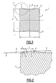
Fig. 1 is a schematic sectional view of a sintered fuel pellet according to the invention, -
Fig. 2 is an enlarged view of area II ofFig. 1 , -
Fig. 3 is a schematic sectional view of a fuel rod according to the invention, -
Fig. 4 is a schematic side view of a nuclear fuel assembly according to the invention. -
Fig. 1 shows a sinteredfuel pellet 1 comprising aperipheral wall 4 and twoend faces 6. The sinteredfuel pellet 1 is intended to be placed in acladding 7 and to be superposed with other similar sintered fuel pellets in order to form a water nuclearreactor fuel rod 8, as shown inFig. 3 . Such afuel rod 8 will be introduced in afuel rod bundle 9 of anuclear fuel assembly 10, thisbundle 9 being held by askeleton 11, as shown inFig. 4 . -
Fig.4 shows atypical fuel assembly 10 with a square array for a PWR. The fuel assemblies 10 for VVER typically have a hexagonal array. The structures used for BWR and PHWR fuel assemblies are also different but the fuel pellets and the fuel rods are similar, the dimensions being adapted to each specific design. In all cases, thecladding 7 is for example made in a zirconium based alloy. - The
peripheral wall 4 extends along a central axis A in an axial direction and the end faces 6 extend from the edges of theperipheral wall 4 towards the central axis A. - For a
fuel pellet 1 used in a PWR, the diameter D of theperipheral wall 4 is usually comprised substantially between 7.4 mm and 9.8 mm depending on the fuel assembly array (mainly 14x14 to 19x19). For instance, the diameter D of afuel pellet 1 for a 17x17 PWR fuel assembly is typically around 8.192 mm. Values for aVVER fuel pellet 1 are similar : for instance D varies typically between 7.51 mm and 7.60 mm for a VVER-1000. - For a
fuel pellet 1 used in a BWR, the diameter D of theperipheral wall 4 is usually comprised substantially between 8.0 mm and 10.3 mm (and can mount up to 12.25 mm for the 6X6 oldest designs) depending on the fuel assembly array (mainly 6X6 to 13X13). For instance, the diameter D of afuel pellet 1 for a 10X10 BWR fuel assembly is typically around 8.670 mm. - For a
fuel pellet 1 used in a PHWR, the diameter D of theperipheral wall 4 is usually comprised substantially between 12.0 mm and 15.3 mm depending on the fuel assembly array. For instance, the diameter D of afuel pellet 1 for a 19-elements bundle PHWR fuel assembly is typically around 14.3 mm. - In all these cases, the ratio between the length H of the
peripheral wall 4 and the diameter D, i.e. H/D, is substantially comprised between 0.6 and 2. For instance, the typical H/D ratio is around 1.6 for a 17x17 PWR fuel pellet, around 0.7 for a VVER fuel pellet, around 1.2 for a 10x10 BWR fuel pellet, and around 1.7 for a PHWR fuel pellet. - According to another embodiment, the
fuel pellet 1 may have a reduced H/D ratio as disclosed inWO-02/45096 fuel pellet 1, for a diameter D substantially equal to 8.192 mm, the H/D ratio is for example comprised between 0.4 and 0.6, and preferably equal to 0.5. - In the shown embodiment, the
end faces 6 are substantially symmetrical relative to a plane P substantially perpendicular to the central axis A and crossing theperipheral wall 4 substantially in its middle. Therefore, only theupper end face 6 will now be described with reference toFigs. 1 and 2 . - The
end face 6 comprises afirst chamfer 12 extending from theperipheral wall 4 towards the central axis A and having a first non-zero slope. The first slope is defined by the angle α between thefirst chamfer 12 and a plane P' perpendicular to the central axis A. The angle α is substantially comprised between 7° and 40°. In a specific embodiment, the angle α is substantially equal to 18°. The dimension h of thefirst chamfer 12 along the axis A is substantially comprised between 0.10 mm and 0.20 mm and is preferably equal to 0.15 mm. The dimension I of thefirst chamfer 12 along the plane P' is substantially comprised between 0.26 mm and 0.66 mm and is preferably equal to 0.46 mm. - The
first chamfer 12 enables to reduce the chipping of thefuel pellet 1 during the manufacturing thereof and eases the loading of thefuel pellet 1 in thecladding 7. It further reduces the risks of degrading thefuel pellet 1 during this loading by suppressing sharp corners between theperipheral wall 4 and the end faces 6. - The
end face 6 further comprises asecond chamfer 14 extending from thefirst chamfer 12 towards the central axis A and having a second non-zero slope different from the first slope. The second slope is defined by the angle β between thesecond chamfer 14 and the plane P'. The angle β is substantially comprised between 0.2°and 10°. In particular, the angle b is substantially comprised between 0.4° and 9°. In a specific embodiment, the angle β is substantially equal to 3°. The dimension h' of thefirst chamfer 12 and thesecond chamfer 14 along the axis A is substantially comprised between 0.15 mm and 0.25 mm and is preferably equal to 0.20 mm. The dimension I' of thesecond chamfer 14 along the plane P' is substantially comprised between 0.64 mm and 1.34 mm and is preferably equal to 0.99 mm. - The first and the second slopes are of the same sign and are directed towards the exterior of the
fuel pellet 1, as shown inFig. 2 . The first slope, which is relatively "steep", is greater than the second slope which is relatively "smooth". - According to an embodiment, the first and the
second chamfers end face 6. - The
second chamfer 14 forms the contact surface of thefuel pellet 1 with its neighboring pellet when thefuel pellets 1 are superposed in acladding 7 to form afuel rod 8. - According to the embodiment of the invention shown in
Figs. 1 to 3 , theend face 6 further comprises a dish-shapedrecess 16 extending from thesecond chamfer 14 and around the central axis A. Therecess 16 is adapted to enable an axial thermal expansion of thefuel pellet 1 when thenuclear fuel rod 8 is used in a nuclear reactor. - The maximal depth of the
recess 16 is located on the central axis A and is for example substantially comprised between 0.1 mm and 0.5 mm and preferably comprised between 0.2 mm and 0.4 mm. - For a
fuel pellet 1 used in a water reactor, the diameter of therecess 16 is substantially comprised between 4.5 mm and 7.2 mm. In a specific embodiment, the diameter of therecess 16 is substantially equal to 5.3 mm for aperipheral wall 4 having a diameter D substantially equal to 8.192 mm and 6.4 mm for aperipheral wall 4 having a diameter D substantially equal to 9.33 mm. Such a dish-shapedrecess 16 and its function are commonly known in fuel pellets and will not be described in greater detail herein. - The above described sintered
fuel pellet 1 is obtained by sintering a green fuel pellet. - The green fuel pellet is obtained by compression of fuel materials, for example a powder comprising uranium oxide with any content of the isotope 235 and/or plutonium oxide with possible addition of burnable poison, such as for instance Gd2O3, into a suitable mold, in order to make the
peripheral wall 4 substantially cylindrical. It is possible to use other fissile material than uranium oxide and/or plutonium oxide or to add other or additional additives than burnable poison such as pore former, lubricant... to obtain the green pellet. - The green fuel pellet has substantially the same shape and slightly larger dimensions than the sintered
fuel pellet 1, which means that it also comprises aperipheral wall 4 and two end faces 6, each comprising a first 12 and a second chamfers 14 and, according to the embodiment shown in the Figs, a dish-shapedrecess 16. - The green fuel pellet is sintered and may be rectified to acquire the final shape and dimensions of the above-described
sintered fuel pellet 1. - During the sintering step of the green fuel pellet, the
second chamfer 14 tends to be moved in axially due to the densification of the fuel material. Because of the second slope, the contact surface will always exhibit a second slope of the same sign than the first slope of thefirst chamfer 12, despite the manufacturing tolerances. Even if the sintering process is carried on for too long, thesecond chamfer 14 will become, at the most, a flat surface. - This will prevent the appearance of a sharp edge between the
first chamfer 12 and the contact surface, formed by thesecond chamfer 14. The contact surface between twosuperposed fuel pellets 1 is therefore guaranteed to be soft so that the risks of chipping are reduced, the contact point between the superposed pellets being shifted to the rim of the dish-shaped recess. - Indeed, the inventors surprisingly discovered that, in the prior art pellets, the risk of chipping was connected to the appearance of a sharp edge between the
first chamfer 12 and the contact surface of the pellets during the sintering of the green pellet. - In the fuel pellets of the prior art, the contact surface, which was intended to be horizontal, could actually exhibit a slope directed towards the inner part of the pellet and inverted relative to the slope of the chamfer, because of the sintering step.
- Therefore a sharp edge could appear between the chamfer and the contact surface.
- With the
second chamfer 14 of the invention, the appearance of such a sharp edge is prevented. The green and sinteredfuel pellets 1 of the invention therefore present a better in-service behavior and a substantial reduction in surface defects, which greatly raises the production yield. Furthermore, the risks of cladding failure are reduced. - As mentioned above, the
fuel pellet 1 of the invention is adapted to be used in a PWR, including WER, as well as in a BWR or in a PHWR. The general shape of thefuel pellet 1 is the same for use in these various types of reactors and only the dimensions of thefuel pellet 1 need to be adapted. - Other variants of the shape of the above-described
fuel pellet 1 are possible. For example, according to another variant, the end faces 6 each have a different shape or exhibit different slope dimensions, recess dimensions, etc. Thus, the end faces 6 are not necessarily symmetrical relative to the plane P.
Claims (15)
- Sintered fuel pellet (1) for a water nuclear reactor fuel rod (8) comprising a peripheral wall (4) extending along a central axis (A) and two end faces (6), wherein at least one of the end faces (6) comprises at least a first chamfer (12) extending from the peripheral wall (4) towards the central axis (A) with a first non-zero slope with respect to a plane perpendicular to the central axis (A) and a second chamfer (14) extending from the first chamfer (12) towards the central axis (A) with a second non-zero slope with respect to a plane perpendicular to the central axis (A), the first and second slopes being of the same sign and being directed towards the exterior of the fuel pellet, wherein the first slope is different from the second slope, the end face further comprising a dish-shaped recess (16) extending from the second chamfer (14) and around the central axis (A).
- Sintered fuel pellet according to claim 1, wherein the first slope is greater than the second slope.
- Sintered fuel pellet according to claim 1 or 2, wherein the first slope is substantially comprised between 7° and 40°.
- Sintered fuel pellet according to any of claims 1 to 3, wherein the second slope is substantially comprised between 0.2° and 10°.
- Sintered fuel pellet according to claim 4, wherein the second slope is substantially comprised between 0.4° and 9°.
- Sintered fuel pellet according to any of claims 1 to 5, wherein the peripheral wall (4) is substantially cylindrical.
- Sintered fuel pellet according to any of claims 1 to 6, wherein the end faces (6) are substantially symmetrical relative to a plane (P) substantially perpendicular to the central axis (A) and crossing the peripheral wall (4) substantially in its middle.
- Sintered fuel pellet according to any of claims 1 to 7, wherein the ratio between the length (H) of the peripheral wall (4) and the diameter (D) of said peripheral wall (4) is substantially comprised between 0.4 and 2.
- Sintered fuel pellet (1) according to any of claims 1 to 8, wherein each end face (6) comprises at least a first chamfer (12) extending from the peripheral wall (4) towards the central axis (A) with a first non-zero slope with respect to a plane perpendicular to the central axis (A) and a second chamfer (14) extending from the first chamfer (12) towards the central axis (A) with a second non-zero slope with respect to a plane perpendicular to the central axis (A), wherein the first slope is different from the second slope.
- Green fuel pellet for a water nuclear reactor fuel rod (8), intended to be sintered to obtain a sintered fuel pellet (1) according to any of claims 1 to 9, comprising a peripheral wall (4) extending along a central axis (A) and two end faces (6), wherein at least one of the end faces (6) comprises at least a first chamfer (12) extending from the peripheral wall (4) towards the central axis (A) with a first non-zero slope with respect to a plane perpendicular to the central axis (A) and a second chamfer (14) extending from the first chamfer (12) towards the central axis (A) with a second non-zero slope with respect to a plane perpendicular to the central axis (A), the first and second slopes being of the same sign and being directed towards the exterior of the fuel pellet, wherein the first slope is different from the second slope, the end face further comprising a dish-shaped recess (16) extending from the second chamfer (14) and around the central axis (A).
- Green fuel pellet according to claim 10, wherein the first slope is substantially comprised between 7° and 40°.
- Green fuel pellet according to claim 10 or 11, wherein the second slope is substantially comprised between 0.2° and 10°.
- Green fuel pellet according to claim 12, wherein the second slope is substantially comprised between 0.4° and 9°.
- Fuel rod (8) for a nuclear fuel assembly (10) comprising a cladding (7) and a stack of sintered fuel pellets (1) in the cladding (7), at least one of the sintered fuel pellets (1) being a pellet according to any of claims 1 to 9.
- Nuclear fuel assembly (10) comprising a skeleton (11) and a bundle (9) of fuel rods (8), wherein at least one of the fuel rods (8) is a fuel rod according to claim 14.
Applications Claiming Priority (2)
| Application Number | Priority Date | Filing Date | Title |
|---|---|---|---|
| PCT/IB2008/055633 WO2010038109A1 (en) | 2008-09-30 | 2008-09-30 | Nuclear reactor green and sintered fuel pellets, corresponding fuel rod and fuel assembly |
| PCT/EP2009/062620 WO2010037748A1 (en) | 2008-09-30 | 2009-09-29 | Nuclear reactor green and sintered fuel pellets, corresponding fuel rod and fuel assembly |
Publications (2)
| Publication Number | Publication Date |
|---|---|
| EP2345040A1 EP2345040A1 (en) | 2011-07-20 |
| EP2345040B1 true EP2345040B1 (en) | 2014-07-23 |
Family
ID=41059903
Family Applications (1)
| Application Number | Title | Priority Date | Filing Date |
|---|---|---|---|
| EP09783555.7A Active EP2345040B1 (en) | 2008-09-30 | 2009-09-29 | Nuclear reactor green and sintered fuel pellets, corresponding fuel rod and fuel assembly |
Country Status (8)
| Country | Link |
|---|---|
| US (1) | US9042507B2 (en) |
| EP (1) | EP2345040B1 (en) |
| JP (1) | JP5762960B2 (en) |
| KR (1) | KR101596431B1 (en) |
| CN (2) | CN107068207B (en) |
| ES (1) | ES2495750T3 (en) |
| TW (1) | TWI501257B (en) |
| WO (2) | WO2010038109A1 (en) |
Families Citing this family (12)
| Publication number | Priority date | Publication date | Assignee | Title |
|---|---|---|---|---|
| US20130114781A1 (en) * | 2011-11-05 | 2013-05-09 | Francesco Venneri | Fully ceramic microencapsulated replacement fuel assemblies for light water reactors |
| US20130322590A1 (en) * | 2011-11-19 | 2013-12-05 | Francesco Venneri | Extension of methods to utilize fully ceramic micro-encapsulated fuel in light water reactors |
| FR2988974B1 (en) * | 2012-04-02 | 2017-09-01 | Commissariat Energie Atomique | DEVICE FOR GENERATING A HIGH GRADIENT OF TEMPERATURE IN A NUCLEAR FUEL TYPE SAMPLE |
| US10720252B2 (en) | 2013-03-14 | 2020-07-21 | Bwxt Mpower, Inc. | Pellet handling apparatus and fuel rod loading method |
| US10109381B2 (en) | 2015-06-22 | 2018-10-23 | Battelle Energy Alliance, Llc | Methods of forming triuranium disilicide structures, and related fuel rods for light water reactors |
| US11049625B2 (en) | 2016-11-25 | 2021-06-29 | Korea Advanced Institute Of Science And Technology | Nuclear fuel pellet with central burnable absorber |
| KR102102975B1 (en) * | 2018-01-24 | 2020-05-29 | 한전원자력연료 주식회사 | Nuclear fuel sintered pellet having excellent impact-fracture-resistance |
| KR102123234B1 (en) * | 2018-01-24 | 2020-06-16 | 한전원자력연료 주식회사 | Nuclear fuel pellet having excellent resistace to compression fracture amd being reduced surface chipping |
| EP3588514B1 (en) * | 2018-06-21 | 2023-09-27 | Westinghouse Electric Sweden AB | Fuel pellet and method of preparing a fuel pellet |
| KR102128532B1 (en) | 2019-10-29 | 2020-06-30 | 한국과학기술원 | Disk-type Burnable Absorber for Nuclear Reactor Fuel |
| RU2741782C1 (en) * | 2020-04-27 | 2021-01-28 | Акционерное Общество "Твэл" | Nuclear fuel pellet |
| CA3151169A1 (en) | 2021-05-11 | 2022-11-11 | Clean Core Thorium Energy Llc | Thorium-based fuel design for pressurized heavy water reactors |
Family Cites Families (9)
| Publication number | Priority date | Publication date | Assignee | Title |
|---|---|---|---|---|
| CA914320A (en) * | 1972-11-07 | Siemens Aktiengesellschaft | Ceramic nuclear fuel or breeder material tablets and method of producing the same | |
| DE1815957A1 (en) * | 1968-12-20 | 1970-07-02 | Siemens Ag | Ceramic nuclear fuel pellet |
| US4129477A (en) * | 1976-12-08 | 1978-12-12 | General Electric Company | Axially alignable nuclear fuel pellets |
| US4664881A (en) * | 1984-03-14 | 1987-05-12 | Westinghouse Electric Corp. | Zirconium base fuel cladding resistant to PCI crack propagation |
| US4778648A (en) * | 1987-04-24 | 1988-10-18 | Westinghouse Electric Corp. | Zirconium cladded pressurized water reactor nuclear fuel element |
| US4814137A (en) * | 1988-02-16 | 1989-03-21 | Westinghouse Electric Corp. | High performance reliability fuel pellet |
| RU1669308C (en) * | 1989-06-26 | 1994-04-30 | Производственное объединение "Машиностроительный завод" | Rod-type fuel element |
| FR2817385B1 (en) * | 2000-11-30 | 2005-10-07 | Framatome Anp | PASTILLE OF NUCLEAR FUEL OXIDE AND PENCIL COMPRISING A STACK OF SUCH PELLETS |
| FR2890767B1 (en) * | 2005-09-09 | 2007-10-19 | Framatome Anp Sas | METHOD FOR DETERMINING AT LEAST ONE FACTOR OF TECHNOLOGICAL UNCERTAINTY OF NUCLEAR FUEL ELEMENTS, DESIGN METHOD, MANUFACTURING METHOD AND METHOD FOR CONTROLLING CORRESPONDING NUCLEAR FUEL ELEMENTS |
-
2008
- 2008-09-30 WO PCT/IB2008/055633 patent/WO2010038109A1/en active Application Filing
-
2009
- 2009-09-29 TW TW098132979A patent/TWI501257B/en not_active IP Right Cessation
- 2009-09-29 EP EP09783555.7A patent/EP2345040B1/en active Active
- 2009-09-29 WO PCT/EP2009/062620 patent/WO2010037748A1/en active Application Filing
- 2009-09-29 KR KR1020117008823A patent/KR101596431B1/en active IP Right Grant
- 2009-09-29 JP JP2011528364A patent/JP5762960B2/en active Active
- 2009-09-29 US US13/121,907 patent/US9042507B2/en active Active
- 2009-09-29 CN CN201611224842.0A patent/CN107068207B/en active Active
- 2009-09-29 CN CN2009801458300A patent/CN102217003A/en active Pending
- 2009-09-29 ES ES09783555.7T patent/ES2495750T3/en active Active
Also Published As
| Publication number | Publication date |
|---|---|
| KR101596431B1 (en) | 2016-02-23 |
| JP5762960B2 (en) | 2015-08-12 |
| KR20110070984A (en) | 2011-06-27 |
| WO2010037748A1 (en) | 2010-04-08 |
| JP2012504228A (en) | 2012-02-16 |
| US20110176650A1 (en) | 2011-07-21 |
| TWI501257B (en) | 2015-09-21 |
| WO2010038109A1 (en) | 2010-04-08 |
| CN107068207B (en) | 2019-06-04 |
| CN102217003A (en) | 2011-10-12 |
| CN107068207A (en) | 2017-08-18 |
| ES2495750T3 (en) | 2014-09-17 |
| TW201021051A (en) | 2010-06-01 |
| EP2345040A1 (en) | 2011-07-20 |
| US9042507B2 (en) | 2015-05-26 |
Similar Documents
| Publication | Publication Date | Title |
|---|---|---|
| EP2345040B1 (en) | Nuclear reactor green and sintered fuel pellets, corresponding fuel rod and fuel assembly | |
| JP6319916B2 (en) | Fuel assembly | |
| US9620248B2 (en) | Dispersion ceramic micro-encapsulated (DCM) nuclear fuel and related methods | |
| RU2012127788A (en) | FUEL ROD AND METHOD FOR PRODUCING TABLETS FOR SUCH ROD | |
| JPH09211163A (en) | Fuel pellet for nuclear fuel rod, fuel rod and nuclear fuel assembly | |
| EP3745418B1 (en) | Nuclear fuel sintered body having excellent impact resistance | |
| JP2007514141A5 (en) | ||
| Carter | Experimental investigation of various pellet geometries to reduce strains in zirconium alloy cladding | |
| JP3177062B2 (en) | Fuel assembly for light water reactor and light water reactor core | |
| EP0613152A1 (en) | Mid-enrichment axial blanket for a nuclear reactor fuel rod | |
| JP4351798B2 (en) | Fuel assemblies and reactors | |
| JPS6055037B2 (en) | fuel rod | |
| JPH0429089A (en) | Fuel assembly | |
| JP4653540B2 (en) | Nuclear reactor core | |
| JP2005098924A (en) | Mox fuel assembly | |
| Prasad et al. | Effect of fuel fabrication parameters on performance-designer's point of view | |
| JPH0376875B2 (en) | ||
| JP2003262692A (en) | Boiling water reactor fuel assembly and determination method for fuel arrangement in the fuel assembly | |
| JP2000298187A (en) | Fuel element for nuclear reactor | |
| Yang et al. | Development of doped-UO2 pellets for a PCI remedy | |
| JPS59187289A (en) | Nuclear fuel rod | |
| JPS6071984A (en) | Fuel rod for light-water reactor | |
| JPH03183989A (en) | Fuel assembly | |
| JPS59184883A (en) | Nuclear fuel rod | |
| JPS6322550B2 (en) |
Legal Events
| Date | Code | Title | Description |
|---|---|---|---|
| PUAI | Public reference made under article 153(3) epc to a published international application that has entered the european phase |
Free format text: ORIGINAL CODE: 0009012 |
|
| 17P | Request for examination filed |
Effective date: 20110420 |
|
| AK | Designated contracting states |
Kind code of ref document: A1 Designated state(s): AT BE BG CH CY CZ DE DK EE ES FI FR GB GR HR HU IE IS IT LI LT LU LV MC MK MT NL NO PL PT RO SE SI SK SM TR |
|
| AX | Request for extension of the european patent |
Extension state: AL BA RS |
|
| DAX | Request for extension of the european patent (deleted) | ||
| 17Q | First examination report despatched |
Effective date: 20120320 |
|
| REG | Reference to a national code |
Ref country code: DE Ref legal event code: R079 Ref document number: 602009025534 Country of ref document: DE Free format text: PREVIOUS MAIN CLASS: G21C0003580000 Ipc: G21C0003040000 |
|
| GRAP | Despatch of communication of intention to grant a patent |
Free format text: ORIGINAL CODE: EPIDOSNIGR1 |
|
| RIC1 | Information provided on ipc code assigned before grant |
Ipc: G21C 3/58 20060101ALI20140203BHEP Ipc: G21C 21/02 20060101ALI20140203BHEP Ipc: G21C 3/04 20060101AFI20140203BHEP |
|
| INTG | Intention to grant announced |
Effective date: 20140219 |
|
| GRAS | Grant fee paid |
Free format text: ORIGINAL CODE: EPIDOSNIGR3 |
|
| GRAA | (expected) grant |
Free format text: ORIGINAL CODE: 0009210 |
|
| AK | Designated contracting states |
Kind code of ref document: B1 Designated state(s): AT BE BG CH CY CZ DE DK EE ES FI FR GB GR HR HU IE IS IT LI LT LU LV MC MK MT NL NO PL PT RO SE SI SK SM TR |
|
| REG | Reference to a national code |
Ref country code: GB Ref legal event code: FG4D |
|
| REG | Reference to a national code |
Ref country code: CH Ref legal event code: EP Ref country code: CH Ref legal event code: NV Representative=s name: ARNOLD AND SIEDSMA AG, CH |
|
| REG | Reference to a national code |
Ref country code: IE Ref legal event code: FG4D |
|
| REG | Reference to a national code |
Ref country code: AT Ref legal event code: REF Ref document number: 679267 Country of ref document: AT Kind code of ref document: T Effective date: 20140815 |
|
| REG | Reference to a national code |
Ref country code: SE Ref legal event code: TRGR |
|
| REG | Reference to a national code |
Ref country code: DE Ref legal event code: R096 Ref document number: 602009025534 Country of ref document: DE Effective date: 20140904 |
|
| REG | Reference to a national code |
Ref country code: ES Ref legal event code: FG2A Ref document number: 2495750 Country of ref document: ES Kind code of ref document: T3 Effective date: 20140917 |
|
| REG | Reference to a national code |
Ref country code: AT Ref legal event code: MK05 Ref document number: 679267 Country of ref document: AT Kind code of ref document: T Effective date: 20140723 |
|
| REG | Reference to a national code |
Ref country code: NL Ref legal event code: VDEP Effective date: 20140723 |
|
| REG | Reference to a national code |
Ref country code: LT Ref legal event code: MG4D |
|
| PG25 | Lapsed in a contracting state [announced via postgrant information from national office to epo] |
Ref country code: BG Free format text: LAPSE BECAUSE OF FAILURE TO SUBMIT A TRANSLATION OF THE DESCRIPTION OR TO PAY THE FEE WITHIN THE PRESCRIBED TIME-LIMIT Effective date: 20141023 Ref country code: GR Free format text: LAPSE BECAUSE OF FAILURE TO SUBMIT A TRANSLATION OF THE DESCRIPTION OR TO PAY THE FEE WITHIN THE PRESCRIBED TIME-LIMIT Effective date: 20141024 Ref country code: PT Free format text: LAPSE BECAUSE OF FAILURE TO SUBMIT A TRANSLATION OF THE DESCRIPTION OR TO PAY THE FEE WITHIN THE PRESCRIBED TIME-LIMIT Effective date: 20141124 Ref country code: NO Free format text: LAPSE BECAUSE OF FAILURE TO SUBMIT A TRANSLATION OF THE DESCRIPTION OR TO PAY THE FEE WITHIN THE PRESCRIBED TIME-LIMIT Effective date: 20141023 Ref country code: LT Free format text: LAPSE BECAUSE OF FAILURE TO SUBMIT A TRANSLATION OF THE DESCRIPTION OR TO PAY THE FEE WITHIN THE PRESCRIBED TIME-LIMIT Effective date: 20140723 |
|
| PG25 | Lapsed in a contracting state [announced via postgrant information from national office to epo] |
Ref country code: PL Free format text: LAPSE BECAUSE OF FAILURE TO SUBMIT A TRANSLATION OF THE DESCRIPTION OR TO PAY THE FEE WITHIN THE PRESCRIBED TIME-LIMIT Effective date: 20140723 Ref country code: NL Free format text: LAPSE BECAUSE OF FAILURE TO SUBMIT A TRANSLATION OF THE DESCRIPTION OR TO PAY THE FEE WITHIN THE PRESCRIBED TIME-LIMIT Effective date: 20140723 Ref country code: CY Free format text: LAPSE BECAUSE OF FAILURE TO SUBMIT A TRANSLATION OF THE DESCRIPTION OR TO PAY THE FEE WITHIN THE PRESCRIBED TIME-LIMIT Effective date: 20140723 Ref country code: LV Free format text: LAPSE BECAUSE OF FAILURE TO SUBMIT A TRANSLATION OF THE DESCRIPTION OR TO PAY THE FEE WITHIN THE PRESCRIBED TIME-LIMIT Effective date: 20140723 Ref country code: AT Free format text: LAPSE BECAUSE OF FAILURE TO SUBMIT A TRANSLATION OF THE DESCRIPTION OR TO PAY THE FEE WITHIN THE PRESCRIBED TIME-LIMIT Effective date: 20140723 Ref country code: HR Free format text: LAPSE BECAUSE OF FAILURE TO SUBMIT A TRANSLATION OF THE DESCRIPTION OR TO PAY THE FEE WITHIN THE PRESCRIBED TIME-LIMIT Effective date: 20140723 Ref country code: IS Free format text: LAPSE BECAUSE OF FAILURE TO SUBMIT A TRANSLATION OF THE DESCRIPTION OR TO PAY THE FEE WITHIN THE PRESCRIBED TIME-LIMIT Effective date: 20141123 |
|
| REG | Reference to a national code |
Ref country code: DE Ref legal event code: R097 Ref document number: 602009025534 Country of ref document: DE |
|
| PG25 | Lapsed in a contracting state [announced via postgrant information from national office to epo] |
Ref country code: EE Free format text: LAPSE BECAUSE OF FAILURE TO SUBMIT A TRANSLATION OF THE DESCRIPTION OR TO PAY THE FEE WITHIN THE PRESCRIBED TIME-LIMIT Effective date: 20140723 Ref country code: SK Free format text: LAPSE BECAUSE OF FAILURE TO SUBMIT A TRANSLATION OF THE DESCRIPTION OR TO PAY THE FEE WITHIN THE PRESCRIBED TIME-LIMIT Effective date: 20140723 Ref country code: RO Free format text: LAPSE BECAUSE OF FAILURE TO SUBMIT A TRANSLATION OF THE DESCRIPTION OR TO PAY THE FEE WITHIN THE PRESCRIBED TIME-LIMIT Effective date: 20140723 Ref country code: IT Free format text: LAPSE BECAUSE OF FAILURE TO SUBMIT A TRANSLATION OF THE DESCRIPTION OR TO PAY THE FEE WITHIN THE PRESCRIBED TIME-LIMIT Effective date: 20140723 Ref country code: MC Free format text: LAPSE BECAUSE OF FAILURE TO SUBMIT A TRANSLATION OF THE DESCRIPTION OR TO PAY THE FEE WITHIN THE PRESCRIBED TIME-LIMIT Effective date: 20140723 Ref country code: LU Free format text: LAPSE BECAUSE OF FAILURE TO SUBMIT A TRANSLATION OF THE DESCRIPTION OR TO PAY THE FEE WITHIN THE PRESCRIBED TIME-LIMIT Effective date: 20140929 Ref country code: DK Free format text: LAPSE BECAUSE OF FAILURE TO SUBMIT A TRANSLATION OF THE DESCRIPTION OR TO PAY THE FEE WITHIN THE PRESCRIBED TIME-LIMIT Effective date: 20140723 Ref country code: CZ Free format text: LAPSE BECAUSE OF FAILURE TO SUBMIT A TRANSLATION OF THE DESCRIPTION OR TO PAY THE FEE WITHIN THE PRESCRIBED TIME-LIMIT Effective date: 20140723 |
|
| PLBE | No opposition filed within time limit |
Free format text: ORIGINAL CODE: 0009261 |
|
| STAA | Information on the status of an ep patent application or granted ep patent |
Free format text: STATUS: NO OPPOSITION FILED WITHIN TIME LIMIT |
|
| PG25 | Lapsed in a contracting state [announced via postgrant information from national office to epo] |
Ref country code: BE Free format text: LAPSE BECAUSE OF NON-PAYMENT OF DUE FEES Effective date: 20140930 |
|
| 26N | No opposition filed |
Effective date: 20150424 |
|
| REG | Reference to a national code |
Ref country code: IE Ref legal event code: MM4A |
|
| PG25 | Lapsed in a contracting state [announced via postgrant information from national office to epo] |
Ref country code: IE Free format text: LAPSE BECAUSE OF NON-PAYMENT OF DUE FEES Effective date: 20140929 |
|
| PG25 | Lapsed in a contracting state [announced via postgrant information from national office to epo] |
Ref country code: SI Free format text: LAPSE BECAUSE OF FAILURE TO SUBMIT A TRANSLATION OF THE DESCRIPTION OR TO PAY THE FEE WITHIN THE PRESCRIBED TIME-LIMIT Effective date: 20140723 |
|
| PG25 | Lapsed in a contracting state [announced via postgrant information from national office to epo] |
Ref country code: SM Free format text: LAPSE BECAUSE OF FAILURE TO SUBMIT A TRANSLATION OF THE DESCRIPTION OR TO PAY THE FEE WITHIN THE PRESCRIBED TIME-LIMIT Effective date: 20140723 |
|
| PG25 | Lapsed in a contracting state [announced via postgrant information from national office to epo] |
Ref country code: MT Free format text: LAPSE BECAUSE OF FAILURE TO SUBMIT A TRANSLATION OF THE DESCRIPTION OR TO PAY THE FEE WITHIN THE PRESCRIBED TIME-LIMIT Effective date: 20140723 |
|
| PG25 | Lapsed in a contracting state [announced via postgrant information from national office to epo] |
Ref country code: BE Free format text: LAPSE BECAUSE OF FAILURE TO SUBMIT A TRANSLATION OF THE DESCRIPTION OR TO PAY THE FEE WITHIN THE PRESCRIBED TIME-LIMIT Effective date: 20140723 Ref country code: TR Free format text: LAPSE BECAUSE OF FAILURE TO SUBMIT A TRANSLATION OF THE DESCRIPTION OR TO PAY THE FEE WITHIN THE PRESCRIBED TIME-LIMIT Effective date: 20140723 Ref country code: HU Free format text: LAPSE BECAUSE OF FAILURE TO SUBMIT A TRANSLATION OF THE DESCRIPTION OR TO PAY THE FEE WITHIN THE PRESCRIBED TIME-LIMIT; INVALID AB INITIO Effective date: 20090929 |
|
| REG | Reference to a national code |
Ref country code: FR Ref legal event code: PLFP Year of fee payment: 8 |
|
| REG | Reference to a national code |
Ref country code: FR Ref legal event code: PLFP Year of fee payment: 9 |
|
| PG25 | Lapsed in a contracting state [announced via postgrant information from national office to epo] |
Ref country code: MK Free format text: LAPSE BECAUSE OF FAILURE TO SUBMIT A TRANSLATION OF THE DESCRIPTION OR TO PAY THE FEE WITHIN THE PRESCRIBED TIME-LIMIT Effective date: 20140723 |
|
| REG | Reference to a national code |
Ref country code: FR Ref legal event code: PLFP Year of fee payment: 10 |
|
| PGFP | Annual fee paid to national office [announced via postgrant information from national office to epo] |
Ref country code: DE Payment date: 20200910 Year of fee payment: 12 |
|
| PGFP | Annual fee paid to national office [announced via postgrant information from national office to epo] |
Ref country code: CH Payment date: 20210920 Year of fee payment: 13 |
|
| REG | Reference to a national code |
Ref country code: DE Ref legal event code: R119 Ref document number: 602009025534 Country of ref document: DE |
|
| PG25 | Lapsed in a contracting state [announced via postgrant information from national office to epo] |
Ref country code: DE Free format text: LAPSE BECAUSE OF NON-PAYMENT OF DUE FEES Effective date: 20220401 |
|
| REG | Reference to a national code |
Ref country code: CH Ref legal event code: PL |
|
| PG25 | Lapsed in a contracting state [announced via postgrant information from national office to epo] |
Ref country code: LI Free format text: LAPSE BECAUSE OF NON-PAYMENT OF DUE FEES Effective date: 20220930 Ref country code: CH Free format text: LAPSE BECAUSE OF NON-PAYMENT OF DUE FEES Effective date: 20220930 |
|
| PGFP | Annual fee paid to national office [announced via postgrant information from national office to epo] |
Ref country code: GB Payment date: 20230920 Year of fee payment: 15 Ref country code: FI Payment date: 20230821 Year of fee payment: 15 |
|
| PGFP | Annual fee paid to national office [announced via postgrant information from national office to epo] |
Ref country code: SE Payment date: 20230922 Year of fee payment: 15 Ref country code: FR Payment date: 20230927 Year of fee payment: 15 |
|
| PGFP | Annual fee paid to national office [announced via postgrant information from national office to epo] |
Ref country code: ES Payment date: 20231006 Year of fee payment: 15 |