EP2344286B1 - Method and device for determining a flatness of a metal strip - Google Patents
Method and device for determining a flatness of a metal strip Download PDFInfo
- Publication number
- EP2344286B1 EP2344286B1 EP09736153.9A EP09736153A EP2344286B1 EP 2344286 B1 EP2344286 B1 EP 2344286B1 EP 09736153 A EP09736153 A EP 09736153A EP 2344286 B1 EP2344286 B1 EP 2344286B1
- Authority
- EP
- European Patent Office
- Prior art keywords
- metal strip
- measuring apparatus
- measuring device
- adjusting device
- measuring
- Prior art date
- Legal status (The legal status is an assumption and is not a legal conclusion. Google has not performed a legal analysis and makes no representation as to the accuracy of the status listed.)
- Active
Links
Images
Classifications
-
- B—PERFORMING OPERATIONS; TRANSPORTING
- B21—MECHANICAL METAL-WORKING WITHOUT ESSENTIALLY REMOVING MATERIAL; PUNCHING METAL
- B21B—ROLLING OF METAL
- B21B38/00—Methods or devices for measuring, detecting or monitoring specially adapted for metal-rolling mills, e.g. position detection, inspection of the product
- B21B38/02—Methods or devices for measuring, detecting or monitoring specially adapted for metal-rolling mills, e.g. position detection, inspection of the product for measuring flatness or profile of strips
-
- G—PHYSICS
- G01—MEASURING; TESTING
- G01B—MEASURING LENGTH, THICKNESS OR SIMILAR LINEAR DIMENSIONS; MEASURING ANGLES; MEASURING AREAS; MEASURING IRREGULARITIES OF SURFACES OR CONTOURS
- G01B11/00—Measuring arrangements characterised by the use of optical techniques
- G01B11/30—Measuring arrangements characterised by the use of optical techniques for measuring roughness or irregularity of surfaces
- G01B11/306—Measuring arrangements characterised by the use of optical techniques for measuring roughness or irregularity of surfaces for measuring evenness
Definitions
- the invention relates to a method and a device for determining a flatness of a metal strip under tension, in particular during cold or hot rolling, with at least one non-contact measuring device, wherein the at least one measuring device in a position with a distance and / or a spatial position relative to the top and / or bottom of the metal strip is arranged.
- the natural frequency of the metal strip is determined with the aid of at least one measuring device in several over the width of the metal strip arranged width sections, wherein the measuring device does not touch the metal strip and from the determined for the width sections natural frequencies a band tension distribution in the metal strip is determined as a measure of the flatness of the metal strip.
- German patent application no. 23 44 170 describes a method for determining the tensile stress distribution across the width of a cold-rolled strip by means of non-contact measurements made in the region of strip longitudinal zones in order to determine the flatness of the strip.
- the DE 198 03 260 A1 describes a device for measuring the tensile stress distribution in a metal strip with a deflection device for deflecting the metal strip, with a measuring device for measuring the deflection of the metal strip and with a computing device for calculating the tensile stress distribution as a function of the deflection of the metal strip, wherein the deflection device as a suction device for suction is formed of the metal strip.
- the DE 100 00 845 A1 discloses a method for noncontact flatness measurement of metal strips made of ferromagnetic materials which pass through strip processing lines or cold rolling mills.
- the DE 199 11 548 A1 describes a method for non-contact flatness measurement of metal strips, according to which longitudinal waves and / or transverse waves are sounded into the metal strip by means of ultrasound exposure whose transit times are measured and based on the changes in the sound velocities at least the longitudinal and / or transverse stress distribution of integrated over the strip thickness longitudinal stresses is measured. From the stress distribution, the corresponding longitudinal residual stress distribution and the resulting unevenness in the respective metal strip is determined.
- the DE 199 47 572 A1 discloses another method for determining the flatness of a strip of material using of at least two radiation sources and a plurality of detectors at a plurality of measuring points measured values are recorded.
- German patent application no. 24 58 606 There is already known a method and apparatus for detecting the flatness of a cold-rolled ferromagnetic strip using non-contact electromagnets.
- the magnets are arranged on a common carrier, which is adjustable perpendicular to the belt surface.
- a controller drive here in the form of a hydraulic cylinder which is connected to knee joints of a toggle lever drive, available.
- the part of the object to be assigned to the method is achieved by a method for determining a flatness of a metal strip under tension, wherein at least one measuring device is arranged in a position with a spacing and / or a spatial position relative to the top and / or bottom of the metal strip, and wherein at least one adjusting device connected to the at least one measuring device that the position of the at least one measuring device relative to the top and / or bottom of the metal strip is adjustable while the metal strip is moved under tension, wherein the position of the at least one measuring device relative to the top and / or bottom of the metal strip by means of at least one electromechanical Adjustment device in the form of a threaded spindle drive or by means of at least one adjustment in the form of a pneumatic or hydraulic wedge adjustment is adjusted.
- the part of the object to be assigned to the device is achieved by a device for determining a flatness of a moving metal strip under tension, in particular according to the method according to the invention, with at least one non-contact measuring device which is in a position with a distance and / or an orientation relative to the top and / or underside of the metal strip is arranged, wherein the device further comprises at least one adjusting device which is connected to the at least one measuring device such that the position of the at least one measuring device is adjustable relative to the top and / or bottom of the moving metal strip, wherein the Position of the at least one measuring device relative to the top and / or the underside of the metal strip by means of at least one electromechanical adjusting device in the form of a threaded spindle drive or by means of at least one adjusting device in the form of a pneumatic or h ydraulischen wedge adjustment is adjustable.
- the available measuring range of the transmitting and / or receiving units or sensors usually used in the at least one measuring device was not recognized as sufficient to compensate for all influences occurring in practice and to ensure a continuous flatness determination.
- a distance between the measuring device and the metal strip or areas of the metal strip lead to incorrect measurements in determining the flatness of the metal strip.
- a skew of a measuring device opposite the surface of the metal strip facing the measuring device also leads to incorrect measurements in the determination of the flatness, provided that the distances between the measuring device and the metal strip at the two sides of the metal strip substantially, i. by at least ⁇ 0.1 mm per meter width of a measuring device, differ from each other.
- a substantially parallel or only slightly oblique alignment of a longitudinal axis of an elongated measuring device with respect to an upper and / or underside of a metal strip is assumed. It lies for example, an oblique orientation or spatial position of a measuring device when the distance of an elongated measuring device to the metal strip across the width of the metal strip changes away. Furthermore, a substantially perpendicular alignment of the longitudinal axis of an elongated measuring device to a strip running direction is assumed, which usually requires no change in measuring operation.
- the method according to the invention and the device according to the invention enable a positionally accurate, continuous change or optimization of the position of at least one measuring device relative to the metal strip, while the metal strip is moved continuously. A standstill of the metal strip to change the position of the at least one measuring device is not required. This allows a quick and uncomplicated adaptation of the position of the measuring device to a specific metal strip or when changing to a different metal band geometry and / or metal strip quality.
- the method and the device according to the invention make it possible to improve the measuring accuracy in determining the flatness of the metal strip and an increased availability of the measurement due to an optimally positioned measuring device.
- Adjustment devices in the form of a threaded spindle drive or a pneumatic or hydraulic wedge adjustment allow automatic adjustment of the position of the measuring device, which can be caused in particular from a greater distance to the metal strip or the device.
- an electromechanical adjusting device in the form of a threaded spindle drive, particularly preferably a ball screw drive, permits particularly high positioning accuracies in the positioning of the measuring device and a very accurate reproducibility of an already set position.
- the setting of a threaded spindle drive is maintained even in the event of failure of the control, for example in the event of a power failure.
- a threaded spindle drive can act directly on the measuring device or allow a change in the position of the at least one measuring device in a preferred embodiment by means of a wedge adjustment.
- the threaded spindle drive thereby drives a wedge adjustment by a spindle of the threaded spindle drive is rotated into a wedge of the wedge adjustment in or out of this to set different wedge positions.
- a “wedge adjustment” is here and hereafter generally understood to mean an adjustment of the position of one or more wedges which act on a movably mounted measuring device, as a result of which a change in the position of the at least one measuring device is effected.
- the wedge is moved horizontally, wherein the inclined surface of the wedge acts on the measuring device and causes a vertical movement of the measuring device.
- An adjusting device in the form of a hydraulic wedge adjustment, in which a wedge is hydraulically driven usually requires a connection to a hydraulic line system, while an adjustment in the form of a pneumatic wedge adjustment in which a wedge is pneumatically driven, usually a connection to a pneumatic line system needed.
- the method according to the invention and the device according to the invention for flatness determination are particularly preferably used on metal strips which are processed in cold or hot rolling mills.
- an application to metal strips, which are processed in continuous systems, such as temper rolling mills or strip processing plants, etc., for example in annealing lines or coating lines, is advantageous.
- the position of the at least one measuring device is adjusted or adjustable by means of the at least one adjusting device relative to the upper side and / or the underside of the metal strip while the metal strip is being moved. This is easier to realize during the tape run than a change in the zero position of the metal band profile.
- the zero line of the metal strip for example by a height adjustment of rollers or the like, be adjustable.
- one measured value is detected or detectable by means of the at least one non-contact measuring device in a plurality of width sections arranged across a width of the metal strip, wherein the flatness of the metal strip is determined or can be determined from the measured values acquired.
- a suitable device for determining the flatness is on the DE 198 03 260 A or the DE 102 57 639 A1 directed.
- the term "next to each other" is intended here to include arrangements in which at least two measuring devices are arranged side by side and directly adjacent to each other, in which at least two measuring devices are arranged side by side and spaced from each other or where at least two measuring devices offset side by side, ie arranged overlapping in the direction of tape travel are.
- an optimum distance to the metal strip can be set for each of the juxtaposed measuring devices or sections thereof.
- the values detected by the juxtaposed measuring devices across the width of the metal strip are preferably combined to form a common data set, which differs from a data set that differs from a single measuring device is detected does not differ significantly.
- a measuring device has at least one, preferably a plurality of transmitting and / or receiving units. If a measuring device has a movable and an immovable section, the at least one transmitting and / or receiving unit is arranged in the movable section. By means of at least one sensor, measured values from which the flatness of the metal strip can be determined precisely and synchronously over the individual width sections can be detected.
- transmitting and / or receiving unit for each width section or for a plurality of width sections.
- the number of transmitting and / or receiving units can be greater, equal or smaller than the number of width sections.
- transmitting and / or receiving units are preferably mounted on a common measuring carriage, wherein the position of the transmitting and / or receiving units relative to the measuring carriage can be fixed or adjustable.
- the at least one adjusting device is designed such that the distance between the at least one measuring device to the top and / or bottom of the metal strip by at least ⁇ 5 mm, in particular by at least ⁇ 10 mm, is adjustable.
- the position of the measuring device via an adjustment, which is in the range of ⁇ 5 mm to ⁇ 50 mm, adjustable or height adjustable.
- a nominal value for the distance between a metal strip and a measuring device is usually in the range of 3.5 to 5 mm. However, other ranges for a target value may be advantageous to reliably determine the flatness of a metal strip.
- a measuring device is arranged to be movable overall or a measuring device has only one movable section comprising the at least one transmitting and / or receiving unit which is connected to a stationary mounted section.
- a seal is preferably arranged between the movable and the stationary mounted portion of a measuring device in order to prevent dust, steam, etc. from penetrating into the interior of the measuring device or being influenced by other influences affecting the operation of the device, which lead to corrosion, for example. to minimize, especially in the case that an interface between the stationary and movable portion of the measuring device in the range of sensitive components of the measuring device is arranged.
- Adjacent measuring devices are preferably arranged so that these or movable sections of these can be adjusted independently of each other in their position by means of at least one adjustment. But it can also be a mechanical connection between juxtaposed measuring devices or movable sections of these be present, which allows a change in position relative to each other.
- the mechanical connection is preferably provided in the form of a hinge, a hinge or the like.
- at least one adjusting device acts on at least one of the measuring devices or their movable section and / or the connection between altogether movable measuring devices or between their movable sections.
- An adjusting device is in particular designed such that the distance between the at least one measuring device to the top and / or bottom of the metal strip at each point with a positioning accuracy in the range of at least ⁇ 100 microns, in particular in the range of ⁇ 10 microns, is adjustable.
- an adjusting device used in the form of a hydraulic or pneumatic wedge adjustment it has proved to be advantageous if during and / or after the adjustment of the position of the at least one measuring device, a mechanical guidance and position stabilization of the at least one measuring device by means of at least one device for exercising a Counterpressure is applied to the measuring device, wherein the back pressure acts on the side facing away from the adjusting device of the measuring device. This increases the positioning accuracy in the positioning of the measuring device as well as a stability in the operation of the device.
- each adjusting device is assigned at least one device for the application of a counter-pressure.
- hydraulic, pneumatic or mechanical counter-pressure springs have proven themselves.
- a mechanical clamping by means of at least one cylinder rod has proved to be suitable for applying a back pressure.
- a mechanical fixation of the measuring device in this position is preferably carried out in order to prevent an unintentional displacement.
- a mechanical fixation is preferably realized by means of at least one clamping device.
- a clamping device is preferably provided via a movable hydraulic cylinder, which acts laterally on the measuring device and clamps them in their position.
- two clamping devices are used, which fix the two sides of the measuring device, which are associated with the edges of the metal strip.
- a distance between the metal strip and the at least one measuring device per width sections is detected in order to obtain the most accurate possible statement about the current position of the measuring device.
- the distances between the metal strip and the measuring device are detected in at least two width sections, which allow a statement regarding the distance between the two sides of the metal strip to the measuring device.
- the at least one measuring device preferably has the two edges or substantially the two edges of the metal strip assigned in each case at least one adjustment.
- a common or synchronous adjustment of two or more adjusting devices is preferably realized by a common drive, while a separate or asynchronous adjustment is realized by each adjusting is assigned in each case a separate, independent drive.
- the asynchronous adjustment of two adjusting devices makes it possible to compensate for an inclined position of an associated measuring device.
- the at least two adjustment preferably means for position detection, such as position sensor or encoders integrated.
- the detected by means of the devices for position detection positions of the adjustment are matched to each other and blocks or precluded an adjustment of the spatial position of the measuring device in the direction of an inadmissible and system damaging skew.
- each adjustment device is required, which can be moved relative to each other in their relative spatial position and / or tilted.
- the spatial position of at least one of the adjusting devices is variable, for example by a hinge, hinge or rail arrangement. But also each individual adjusting device or a selected group of adjusting devices can be made changeable in their spatial position.
- the detection of at least one distance between the metal strip and the measuring device in the region of the center of the metal strip has proven itself in order reliably to detect possible warping or folds in the metal strip.
- the device according to the invention preferably comprises at least one control unit in which setpoint values for the positioning of the measuring device are stored or can be determined, wherein a change of the detected position in the direction of the setpoint values can be undertaken by means of the at least one control unit.
- an evaluation unit is preferably integrated, with which the flatness determination is performed.
- an evaluation unit can also be present independently of the control unit and be connected to it only via a data line.
- the distances detected in the width sections are preferably transmitted to the at least one control unit, in which setpoint values for the positioning of the measuring device are stored or determined, wherein the at least one control unit causes a change in the position of the measuring device in the direction of the setpoint values as far as this is concerned is required.
- a setpoint is generated by manually or automatically generated data, which may be subjected to a calculation or evaluation routine.
- Setpoints can be stored for comparison purposes firmly in the device, in particular the control unit, and / or be regenerated at each required repositioning of the measuring device (s).
- the control unit preferably generates at least one control signal, which is used for manual and / or automatic activation of the at least one adjusting device.
- the at least one adjusting device is adjusted such that the at least one measuring device is protected against mechanical damage by the metal strip.
- the measuring device is driven in a safe parking position. This is particularly advantageous if a demolition of the metal strip occurs, the metal strip oscillates unacceptably strong, the preset by the adjustment adjustment for adjusting the position of the measuring device is no longer sufficient, an impermissible tilt of the measuring device would have to be set, etc., so that a Damage to the measuring device can be excluded.
- At least one desired value for positioning the measuring device is determined based on at least one process parameter, wherein the process parameter is a geometry of the metal strip and / or a quality of the metal strip and / or other process parameters, such as the position of a zero position of the metal strip, concerns.
- a device for position detection such as a position transmitter or rotary encoder
- a position transmitter or rotary encoder it has likewise proven itself, for example, if the position data acquired thereby are used as other process parameters by means of a serial data link (for example SSI or Profibus) or by means of pulse decoupling the at least one control unit is transmitted for display, calibration and control.
- a serial data link for example SSI or Profibus
- a process parameter is selected from the group comprising a hardness of the metal strip, an E-modulus of the metal strip, a thickness of the metal strip, a width of the metal strip, a tensile force on the metal strip and coordinates with respect to a spatial position or temporal sequence of the spatial position of a zero position of the metal strip , Furthermore, it is advantageous if a cross-sectional area of the metal strip, an amplitude and / or frequency of the vibration of the metal strip, the freely oscillating length of the metal strip, etc. are detected as process parameters and used for setpoint formation.
- the at least one process parameter can be detected manually and / or automatically, in particular by means of or in the control unit.
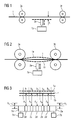
- Fig. 1 schematically shows a section of a rolling train in the side view.
- a metal strip 1, of which only one section is shown here is transported continuously under tension from a first rolling stand 3a in the direction of a second rolling stand 3b.
- a device for determining the flatness of the moving metal strip 1 is arranged by means of a non-contact measuring device 2a, which in this embodiment is arranged in a plurality of width sections b1, b2, b3, arranged over the width of the metal strip 1, b4, b5 (see FIG. 3 ) in each case a measured value is detected, and wherein the flatness of the metal strip 1 is determined from the detected measured values.
- the flatness determination is carried out in particular according to DE 198 03 260 A or the DE 102 57 639 A1 , but can also be done otherwise.
- the measuring device 2a is arranged in a position with a distance A perpendicular to the longitudinal axis of the metal strip 1 and the underside of the metal strip 1 aligns.
- the device further comprises two adjusting devices 7a, 7b (see also FIG. 3 ), which is so connected to the measuring device 2a, that the position of the measuring device 2a relative to the underside of the moving metal strip 1, as indicated by the double arrow, is adjustable.
- the adjusting devices 7a, 7b are the distance A and / or the spatial position of the measuring device 2a relative to the metal strip 1 changeable.
- the adjusting 7a, 7b are realized either by a respective threaded spindle drive or a pneumatic or hydraulic wedge adjustment (see FIGS. 7 to 10 ).
- Fig. 2 shows the schematic side view according to FIG. 1 including further details.
- the metal strip 1 is, as already in FIG. 1 , shown in its zero position, around which the metal strip 1 moves.
- the oscillation width of the metal strip 1 about the zero position is shown by the dashed lines 1a, 1b.
- the position of the measuring device 2a is set optimally by means of the adjusting devices 7a, 7b, whereby no collision with the oscillating metal strip 1 moving from the first rolling stand 3a in the direction of the second rolling stand 3b can occur.
- the measuring device 2a may also be arranged above the metal strip 1 or to the left or right of the antinode or otherwise displaced therefrom.
- FIG. 3 shows a schematic view of the arrangement according to FIG. 2 in cross section through the metal strip 1 at the level of the device comprising the measuring device 2a and the two adjusting devices 7a, 7b.
- the metal strip 1 is shown in its zero position, wherein the oscillation width of the metal strip 1 around the zero position on the dashed lines 1a, 1b is shown (see also FIG. 2 ).
- the measuring device 2a has five transmitting and / or receiving units 2a 'which are each assigned to a width section b1, b2, b3, b4, b5 of the metal strip 1 and are mounted on a common measuring slide 2a "'can be mounted stationary on the measuring slide 2a ", so that their position to each other not can be changed.
- the transmitting and / or receiving units 2a ' can be arranged on the measuring slide such that their position relative to each other, manually or preferably automatically, can be changed.
- the transmitting and / or receiving units 2a ' serve, in particular, for determining the flatness on the metal strip 1.
- a distance A1, A2, A3, A4, A5 in the respective width section b1, b2, b3, b4, b5 are determined, wherein the determined distance values serve to adjust the position of the measuring device 2a in the direction of a desired value.
- the transmitting and / or receiving units 2a ' preferably consist of optical sensors arranged in series.
- the sensors work without contact.
- the measuring device 2a may have only a single sensor. The measured values are recorded in particular over the entire width range and in all width sections b1, b2, b3, b4, b5 at the same time.
- the measuring slide 2a is connected at its two sides assigned to the edges of the metal strip 1 to a permanently mounted adjusting device 7a, 7b, each of which comprises a position indicator not shown separately here opposite the metal band 1 such that the distances A1, A2, A3, A4, A5 can be adjusted and optimized continuously or stepwise.
- An inclination of the measuring carriage 2a "with respect to the zero position of the metal strip 1 of, for example, ⁇ 1 mm can usually also be compensated for by means of the two adjusting devices 7a, 7b realized either by one threaded spindle drive or one each pneumatic or hydraulic wedge adjustment (see FIGS. 7 to 10 ).
- the maximum possible displacement V1, V2, on which the measuring device 2a can be moved in the direction of the underside of the metal strip 1 or away, is in FIG. 3 also shown.
- a change in position is effected at least by means of one of the adjusting devices 7a, 7b.
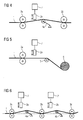
- FIG. 4 shows a schematic side view of another rolling mill arrangement with a looper 4a.
- a non-contact device for determining the flatness of the moving metal strip 1 comprising a measuring device 2a and an adjusting device 7 is arranged above the metal strip 1 between the first rolling stand 3a and the loop lifter 4a.
- a further device for determining the flatness of the moving metal strip 1 between the loop lifter 4a and the second rolling stand 3b can be arranged.
- Fig. 5 shows a schematic side view of another arrangement for carrying out a method with a deflection roller 5 and a reel 6, on which the metal strip 1 wound becomes.
- a device for determining the flatness of the moving metal strip 1 comprising a measuring device 2a and an adjusting device 7, for example in the form of a threaded spindle drive, is arranged above the metal strip 1 between the first rolling stand 3a and the reel 6.
- the deflection roller 5 is located between the first rolling stand 3a and the reel 6 or between the device for determining flatness and the reel 6.
- first rolling stand 3a and the device comprising the measuring device 2a may optionally a so-called, not shown here roll of tape, such as Bandessuh Trentsrolle, an Anticrimpingrolle, Anticrossbowrolle, a pinch roller and the like, be pivoted or levitated, which is placed on the top or bottom of the metal strip 1 and the position of the zero line of the metal strip 1 changed.
- roll of tape such as Bandessuh Trentsrolle, an Anticrimpingrolle, Anticrossbowrolle, a pinch roller and the like
- Fig. 6 shows a schematic side view of a multi-stand rolling mill arrangement for carrying out a method with a device for determining flatness, the two measuring devices 2a, 2b and two adjusting devices 7, 7 ', for example in the form of a threaded spindle drive comprises.
- the section of the rolling train shown here comprises the first rolling stand 3a, the second rolling stand 3b, a third rolling stand 3c and two loop lifters 4a, 4b, between the first rolling stand 3a and the second rolling stand 3b and between the second rolling stand 3b and the third rolling stand 3c each a loop lifter 4a, 4b is arranged.
- the measuring device 2a with the adjusting device 7 is located between the first rolling stand 3a and the loop lifter 4a, while the measuring device 2b with the adjusting device 7 'is located between the second rolling stand 3b and the loop lifter 4b.
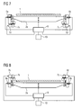
- Fig. 7 shows a schematic view of a first device for determining flatness and a metal strip 1 in cross section at the height of a measuring device 2a.
- the measuring device 2a is arranged vertically adjustable below the metal strip 1.
- the measuring device 2a is connected on both sides with a respective electromechanical adjusting device 7a, 7b, which are realized here in the form of on the side facing away from the metal strip 1 side of the measuring device 2a threaded spindle drives.
- the threaded spindle drives each comprise a drive motor 7a ', 7b' in the form of a servomotor.
- a control unit 9 not only undertakes the detection of measured data recorded with the measuring device 2a with regard to the belt tension or flatness, but also of distances measured between the measuring device 2a and the metal belt 1 over the width of the metal belt 1.
- the communication between the control unit 9 and the measuring device 2a is indicated only schematically by a connecting line between the two elements.
- the control unit 9 is connected to an optional input unit 10, for example in the form of a control panel.
- process parameters are input or fed via the input unit 10 and transmitted to the control unit 9.
- process parameters relating to the geometry of the metal strip 1, the nature or quality of the metal strip 1 as well as plant-related parameters, in particular regarding the zero position of the metal strip 1 in the rolling train are taken into account.
- the process parameters are used to provide or determine at least one desired value for the position of the measuring device 2a relative to the metal strip 1.
- the at least one desired value is then compared with the distance values measured by the measuring device 2a or the optionally determined position values therefrom and if required at least one control signal is generated and transmitted to the two adjusting devices 7a, 7b.
- the at least one control signal causes the actual value of the position of the measuring device 2a to be adjusted to the desired value by means of the adjusting devices 7a, 7b.
- the measuring device 2a is moved by means of the threaded spindle drives upwards in the direction of the metal strip 1 or away from the metal strip 1. To compensate for a tilt of the measuring device 2a relative to the metal strip 1 and a only one-sided or opposite movement on the threaded spindle drives is adjustable.
- clamping devices 8a, 8b here in the form of hydraulic clamping cylinders, are activated by means of the control unit 9, which fix the measuring device in its current position and secure against unintended changes in position.
- a change in the process parameters for example by a metal strip change, which is communicated to the control unit 9, in particular by means of the input unit 10
- at least one new setpoint for the position of the measuring device 2a is determined in the control unit 9, outputs a signal which causes a release of the clamping cylinder and the actual value of the position of the measuring device 2a by means of the adjusting devices 7a, 7b in the direction of the new at least one Setpoint changed.
- the hydraulic clamping cylinder can also be omitted.
- the communication between the control unit 9 and the individual components of the device for determining the flatness, such as the measuring device 2a, the adjusting devices 7a, 7b including the drive motors 7a ', 7b' and the clamping devices 8a, 8b, is shown only schematically.
- the operation of a hydraulic clamping cylinder requires a hydraulic line system, which has not been shown here for the sake of clarity.
- Fig. 8 shows a schematic view of a second device and a metal strip 1 in cross-section at the level of the measuring device 2a.
- the second device is in principle like the first device according to FIG. 7 built up.
- the adjusting devices 7a, 7b including the drive motors 7a ', 7b' are now on the side of the measuring device 2a, which faces the metal strip 1.
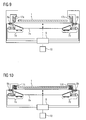
- Fig. 9 shows a schematic view of a third device for determining flatness and a metal strip 1 in cross-section at the level of the measuring device 2a.
- the measuring device 2a is also arranged vertically adjustable below the metal strip 1.
- the measuring device 2a is connected on both sides with a respective hydraulic adjusting device 7a, 7b, which is realized here in the form of a hydraulic wedge adjustment, which is located on the side facing away from the metal strip 1 of the measuring device 2a.
- a pneumatic wedge adjustment can be used.
- a wedge adjustment by means of a threaded spindle drive is alternatively usable, wherein the spindle of the threaded spindle drive into or out of the wedge to set different wedge positions.
- the displaceable wedges of the hydraulic wedge adjustment are controlled on both sides in each case with a proportional valve, which is controlled by means of an electronic analog output.
- the adjustment range of the wedges is for example in the range of ⁇ 50 mm. With an assumed slope of the wedge surfaces of 10% results in a proportional adjustment of the measuring device 2a of ⁇ 5 mm.
- the dimensions with regard to the adjustment range and the wedges are to be selected separately for the respective application and their parameters and are therefore listed here by way of example only.
- the measuring device 2a On the metal strip 1 facing side of the measuring device 2a are two devices 17a, 17b for exerting a back pressure on the measuring device 2a, here in the form of hydraulic impression cylinders, which increase the positioning accuracy of the system.
- the impression cylinders press the measuring device 2a permanently against the wedges of the hydraulic wedge adjustment.
- a control unit 9 and an optional input unit 10 take over in principle already FIG. 7 described tasks.
- the control unit 9 takes over the control of the hydraulic impression cylinder.
- the actual value of the position of the measuring device 2a is here also adapted to the desired value by means of the adjusting devices 7a, 7b.
- the measuring device 2a is moved by means of the hydraulic wedge adjustment upwards in the direction of the metal strip 1 or away from the metal strip 1.
- an inclined position of the measuring device 2a relative to the metal strip 1 is also an opposite movement of the two sides of the measuring device 2a via the hydraulic wedge adjustment adjustable.
- any desired clamping devices 8a, 8b here in the form of hydraulic clamping cylinders, are activated by means of the control unit 9, which fix the measuring device in its current position and secure it against unintentional changes in position.
- a change in the process parameters for example by a metal strip change, which is communicated to the control unit 9, for example by means of the input unit 10
- at least one new setpoint for the position of the measuring device 2a is determined in the control unit 9
- a control signal is output, which triggers a release of the clamping cylinder and the actual value of the position of the measuring device 2a is changed by means of the adjusting devices 7a, 7b in the direction of the new at least one desired value.
- the clamping devices 8a, 8b can also be omitted.
- the communication between the control unit 9 and the individual components of the third flatness measuring device, such as the measuring device 2a, the adjusting devices 7a, 7b, the devices 17a, 17b for exerting a backpressure in the form of hydraulic counter-pressure cylinders and the clamping devices 8a, 8b in the form of hydraulic Clamping cylinder, is like in FIG. 7 only shown schematically. It is obvious, for example, that the operation of a hydraulic impression cylinder and / or a hydraulic clamping cylinder requires a hydraulic line system, which has not been shown here for the sake of clarity.
- Fig. 10 shows a schematic view of a fourth device for determining flatness and a metal strip 1 in cross-section at the level of the measuring device 2a, which is constructed in principle as the third device according to FIG. 9 ,
- the hydraulic impression cylinders have been replaced by means 17c, 17d for the exercise of a back pressure in the form of mechanical counter-pressure springs, which require neither a control means of the control unit 9 nor a hydraulic line system.
Abstract
Description
Die Erfindung betrifft ein Verfahren und eine Vorrichtung zur Ermittlung einer Planheit eines Metallbandes unter Zug, insbesondere beim Kalt- oder Warmwalzen, mit mindestens einer berührungslos arbeitenden Messvorrichtung, wobei die mindestens eine Messvorrichtung in einer Position mit einem Abstand und/oder einer Raumlage relativ zur Oberseite und/oder Unterseite des Metallbands angeordnet wird.The invention relates to a method and a device for determining a flatness of a metal strip under tension, in particular during cold or hot rolling, with at least one non-contact measuring device, wherein the at least one measuring device in a position with a distance and / or a spatial position relative to the top and / or bottom of the metal strip is arranged.
Beim Walzen von Metallbändern treten Einflüsse auf, die die Planheit bzw. Ebenheit des Metallbandes beeinträchtigen. Insbesondere beim Kaltwalzen treten Defizite auf bei der Messung und Beeinflussung der Planheit zwischen den Gerüsten mehrgerüstiger Walzstrassen bzw. zwischen einem Gerüst und einer Umlenkrolle bzw. einem Haspel. Vor allem beim Kaltwalzen tritt bei bestimmten Planheitsfehlern die Gefahr von Bandrissen und/oder Faltenbildung mit diversen Folgeproblemen auf.When rolling metal strips occur influences that affect the flatness or flatness of the metal strip. In particular, during cold rolling, deficits occur in the measurement and influencing of the flatness between the stands of multi-stand rolling trains or between a stand and a deflection roller or a reel. Especially during cold rolling occurs in certain flatness errors, the risk of banding and / or wrinkling with various secondary problems.
Es sind bereits diverse Verfahren und Vorrichtungen zur Planheitsmessung bekannt.Various methods and devices for measuring the flatness are already known.
Gemäß der
Die deutsche Offenlegungsschrift Nr.
Die
Die
Die
Die
In der Praxis hat es sich gezeigt, dass bestimmte Verfahrensparameter, insbesondere hinsichtlich der Produktionsbedingungen und der Ausgestaltung des zu vermessenden Metallbands, einen wesentlichen bzw. ungünstigen Einfluss auf die vollständige Abbildung des abstandsbezogenen Messbereichs haben.In practice, it has been shown that certain process parameters, in particular with regard to the production conditions and the design of the metal strip to be measured, have a significant or unfavorable influence on the complete mapping of the distance-related measuring range.
Aus der deutschen Offenlegungsschrift Nr.
Es ist Aufgabe der Erfindung, ein Verfahren und eine Vorrichtung der eingangs genannten Art anzugeben, mit welchen die Positioniergenauigkeit einer Messvorrichtung zur Ermittlung einer Planheit eines Metallbandes sowie deren Betriebssicherheit erhöht werden kann.It is an object of the invention to provide a method and a device of the type mentioned, with which the positioning accuracy of a measuring device for determining a flatness of a metal strip and their reliability can be increased.
Der dem Verfahren zuzuordnende Teil der Aufgabe wird gelöst durch ein Verfahren zur Ermittlung einer Planheit eines Metallbandes unter Zug, wobei mindestens eine Messvorrichtung in einer Position mit einem Abstand und/oder einer Raumlage relativ zur Oberseite und/oder Unterseite des Metallbands angeordnet wird, und wobei mindestens eine Verstelleinrichtung derart mit der mindestens einen Messvorrichtung verbunden wird, dass die Position der mindestens einen Messvorrichtung relativ zur Oberseite und/oder Unterseite des Metallbands verstellbar ist, während das Metallband unter Zug bewegt wird, wobei die Position der mindestens einen Messvorrichtung gegenüber der Oberseite und/oder der Unterseite des Metallbands mittels mindestens einer elektromechanischen Verstelleinrichtung in Form eines Gewindespindeltriebs oder mittels mindestens einer Verstelleinrichtung in Form einer pneumatischen oder hydraulischen Keilverstellung verstellt wird.The part of the object to be assigned to the method is achieved by a method for determining a flatness of a metal strip under tension, wherein at least one measuring device is arranged in a position with a spacing and / or a spatial position relative to the top and / or bottom of the metal strip, and wherein at least one adjusting device connected to the at least one measuring device that the position of the at least one measuring device relative to the top and / or bottom of the metal strip is adjustable while the metal strip is moved under tension, wherein the position of the at least one measuring device relative to the top and / or bottom of the metal strip by means of at least one electromechanical Adjustment device in the form of a threaded spindle drive or by means of at least one adjustment in the form of a pneumatic or hydraulic wedge adjustment is adjusted.
Der der Vorrichtung zuzuordnende Teil der Aufgabe wird gelöst durch eine Vorrichtung zur Ermittlung einer Planheit eines bewegten Metallbandes unter Zug, insbesondere nach dem erfindungsgemäßen Verfahren, mit mindestens einer berührungslos arbeitenden Messvorrichtung, die in einer Position mit einem Abstand und/oder einer Raumlage relativ zur Oberseite und/oder Unterseite des Metallbands angeordnet ist, wobei die Vorrichtung weiterhin mindestens eine Verstelleinrichtung aufweist, die derart mit der mindestens einen Messvorrichtung verbunden ist, dass die Position der mindestens einen Messvorrichtung relativ zur Oberseite und/oder Unterseite des bewegten Metallbands verstellbar ist, wobei die Position der mindestens einen Messvorrichtung gegenüber der Oberseite und/oder der Unterseite des Metallbands mittels mindestens einer elektromechanischen Verstelleinrichtung in Form eines Gewindespindeltriebs oder mittels mindestens einer Verstelleinrichtung in Form einer pneumatischen oder hydraulischen Keilverstellung verstellbar ist.The part of the object to be assigned to the device is achieved by a device for determining a flatness of a moving metal strip under tension, in particular according to the method according to the invention, with at least one non-contact measuring device which is in a position with a distance and / or an orientation relative to the top and / or underside of the metal strip is arranged, wherein the device further comprises at least one adjusting device which is connected to the at least one measuring device such that the position of the at least one measuring device is adjustable relative to the top and / or bottom of the moving metal strip, wherein the Position of the at least one measuring device relative to the top and / or the underside of the metal strip by means of at least one electromechanical adjusting device in the form of a threaded spindle drive or by means of at least one adjusting device in the form of a pneumatic or h ydraulischen wedge adjustment is adjustable.
Es hat sich gezeigt, dass es abhängig von der Geometrie eines Metallbands, der metallurgischen Beschaffenheit eines Metallbands und den Produktionsbedingungen bei der Herstellung eines Metallbands im Wesentlichen eine optimale Position für die mindestens eine berührungslos arbeitende Messvorrichtung relativ zum Metallband gibt, in der die Planheitsermittlung im Allgemeinen ohne Einschränkungen durchführbar ist.It has been found that depending on the geometry of a metal strip, the metallurgical nature of a metal strip and the production conditions in the production of a metal strip substantially an optimal position for the at least one non-contact measuring device relative to the metal strip in which the flatness determination is generally carried out without restrictions.
Der zur Verfügung stehende Messbereich der in der mindestens einen Messvorrichtung üblicherweise eingesetzten Sende- und/oder Empfangseinheiten bzw. Sensoren wurde als nicht ausreichend erkannt, um alle in der Praxis auftretenden Einflüsse zu kompensieren und eine kontinuierliche Planheitsermittlung sicherzustellen.The available measuring range of the transmitting and / or receiving units or sensors usually used in the at least one measuring device was not recognized as sufficient to compensate for all influences occurring in practice and to ensure a continuous flatness determination.
Ein zu großer wie auch ein zu kleiner Abstand zwischen der Messvorrichtung und dem Metallband oder Bereichen des Metallbands führen zu Fehlmessungen bei der Bestimmung der Planheit des Metallbands. Aber auch eine Schräglage einer Messvorrichtung gegenüber der Oberfläche des Metallbands, welche zur Messvorrichtung zeigt, führt zu Fehlmessungen bei der Bestimmung der Planheit, sofern die Abstände zwischen der Messvorrichtung und dem Metallband an den beiden Seiten des Metallbands wesentlich, d.h. um wenigstens ± 0,1 mm pro Meter Breite einer Messvorrichtung, voneinander abweichen.Excessively large or too small a distance between the measuring device and the metal strip or areas of the metal strip lead to incorrect measurements in determining the flatness of the metal strip. However, a skew of a measuring device opposite the surface of the metal strip facing the measuring device also leads to incorrect measurements in the determination of the flatness, provided that the distances between the measuring device and the metal strip at the two sides of the metal strip substantially, i. by at least ± 0.1 mm per meter width of a measuring device, differ from each other.
Die Position einer Messvorrichtung relativ zum Metallband ist dabei im Wesentlichen bestimmt über einen Abstand zwischen der Messvorrichtung und dem Metallband in Nulllage (= Ebene, um die sich das Metallband bewegt) oder über die Abstände zwischen der Messvorrichtung und Bereichen des Metallbands in Nulllage, sowie die Raumlage der Messvorrichtung relativ zum Metallband, insbesondere zur Oberfläche des Metallbands, welche zur Messvorrichtung zeigt.The position of a measuring device relative to the metal strip is essentially determined by a distance between the measuring device and the metal strip in the zero position (= plane around which the metal belt moves) or the distances between the measuring device and areas of the metal strip in zero position, and the Position of the measuring device relative to the metal strip, in particular to the surface of the metal strip, which points to the measuring device.
Im Allgemeinen wird von einer im Wesentlichen parallelen oder aber nur geringfügig schrägen Ausrichtung einer Längsachse einer langgestreckten Messvorrichtung gegenüber einer Ober-und/oder Unterseite eines Metallbands ausgegangen. Es liegt beispielsweise eine schräge Ausrichtung oder Raumlage einer Messvorrichtung vor, wenn sich der Abstand einer langgestreckten Messvorrichtung zum Metallband über die Breite des Metallbands hinweg verändert. Weiterhin wird von einer im Wesentlichen senkrechten Ausrichtung der Längsachse einer langgestreckten Messvorrichtung zu einer Bandlaufrichtung ausgegangen, die im Messbetrieb üblicherweise keiner Veränderung bedarf.In general, a substantially parallel or only slightly oblique alignment of a longitudinal axis of an elongated measuring device with respect to an upper and / or underside of a metal strip is assumed. It lies For example, an oblique orientation or spatial position of a measuring device when the distance of an elongated measuring device to the metal strip across the width of the metal strip changes away. Furthermore, a substantially perpendicular alignment of the longitudinal axis of an elongated measuring device to a strip running direction is assumed, which usually requires no change in measuring operation.
Das erfindungsgemäße Verfahren und die erfindungsgemäße Vorrichtung ermöglichen eine besonders positionsgenaue, kontinuierliche Änderung bzw. Optimierung der Position mindestens einer Messvorrichtung relativ zum Metallband, während das Metallband kontinuierlich fortbewegt wird. Ein Stillstand des Metallbands zur Änderung der Position der mindestens einen Messvorrichtung ist nicht erforderlich. Dies ermöglicht eine schnelle und unkomplizierte Anpassung der Position der Messvorrichtung an ein bestimmtes Metallband oder bei einem Wechsel zu einer unterschiedlichen Metallband-Geometrie und/oder Metallband-Qualität.The method according to the invention and the device according to the invention enable a positionally accurate, continuous change or optimization of the position of at least one measuring device relative to the metal strip, while the metal strip is moved continuously. A standstill of the metal strip to change the position of the at least one measuring device is not required. This allows a quick and uncomplicated adaptation of the position of the measuring device to a specific metal strip or when changing to a different metal band geometry and / or metal strip quality.
Auch auf veränderte Produktionsbedingungen, wie eine Verstellung des Bandlaufs aufgrund von variabel verstellbaren Positionen von Walzen, eine Veränderung des Bandzugs, eine auftretende Verwölbung innerhalb des Metallbands usw., welche mit einer Änderung der Nulllage des Metallbands oder Teilen des Metallbands einher gehen, kann zeitnah reagiert werden und die Position einer Messeinrichtung stets optimal gegenüber dem Metallband eingestellt werden.Also on changed production conditions, such as an adjustment of the tape run due to variably adjustable positions of rollers, a change in the strip tension, an occurring warping within the metal strip, etc., which go hand in hand with a change in the zero position of the metal strip or parts of the metal strip, can respond promptly be adjusted and the position of a measuring device always optimally against the metal strip.
Weiterhin ermöglichen das erfindungsgemäße Verfahren und die erfindungsgemäße Vorrichtung eine Verbesserung der Messgenauigkeit bei der Bestimmung der Planheit des Metallbands und eine erhöhte Verfügbarkeit der Messung aufgrund einer optimal positionierten Messvorrichtung.Furthermore, the method and the device according to the invention make it possible to improve the measuring accuracy in determining the flatness of the metal strip and an increased availability of the measurement due to an optimally positioned measuring device.
Verstelleinrichtungen in Form eines Gewindespindeltriebs oder einer pneumatischen oder hydraulischen Keilverstellung ermöglichen eine automatische Verstellung der Position der Messvorrichtung, die insbesondere auch aus größerer Entfernung zum Metallband bzw. zur Vorrichtung veranlasst werden kann.Adjustment devices in the form of a threaded spindle drive or a pneumatic or hydraulic wedge adjustment allow automatic adjustment of the position of the measuring device, which can be caused in particular from a greater distance to the metal strip or the device.
Der erfindungsgemäße Einsatz einer elektromechanischen Verstelleinrichtung in Form eines Gewindespindeltriebs, besonders bevorzugt eines Kugelgewindetriebs, ermöglicht besonders hohe Positioniergenauigkeiten bei der Positionierung der Messvorrichtung und eine sehr genaue Reproduzierbarkeit einer bereits früher eingestellten Position. Die Einstellung eines Gewindespindeltriebs bleibt auch bei Ausfall der Ansteuerung, beispielsweise bei einem Stromausfall, erhalten. Ein Gewindespindeltrieb kann dabei unmittelbar auf die Messvorrichtung einwirken oder eine Änderung der Position der mindestens einen Messvorrichtung in einer bevorzugten Ausführungsform mittels einer Keilverstellung ermöglichen. Der Gewindespindeltrieb treibt dabei eine Keilverstellung an, indem eine Spindel des Gewindespindeltriebs in einen Keil der Keilverstellung hinein oder aus diesem heraus gedreht wird, um unterschiedliche Keilpositionen einzustellen.The use according to the invention of an electromechanical adjusting device in the form of a threaded spindle drive, particularly preferably a ball screw drive, permits particularly high positioning accuracies in the positioning of the measuring device and a very accurate reproducibility of an already set position. The setting of a threaded spindle drive is maintained even in the event of failure of the control, for example in the event of a power failure. A threaded spindle drive can act directly on the measuring device or allow a change in the position of the at least one measuring device in a preferred embodiment by means of a wedge adjustment. The threaded spindle drive thereby drives a wedge adjustment by a spindle of the threaded spindle drive is rotated into a wedge of the wedge adjustment in or out of this to set different wedge positions.
Unter einer "Keilverstellung" wird hier und nachfolgend allgemein eine Verstellung der Lage von einem oder mehreren Keilen verstanden, die auf eine beweglich gelagerte Messvorrichtung einwirken, wodurch in Folge eine Änderung der Position der mindestens einen Messvorrichtung bewirkt wird. Der Keil wird dabei insbesondere horizontal bewegt, wobei die schräge Fläche des Keils an der Messvorrichtung angreift und eine vertikale Bewegung der Messvorrichtung bewirkt.A "wedge adjustment" is here and hereafter generally understood to mean an adjustment of the position of one or more wedges which act on a movably mounted measuring device, as a result of which a change in the position of the at least one measuring device is effected. In particular, the wedge is moved horizontally, wherein the inclined surface of the wedge acts on the measuring device and causes a vertical movement of the measuring device.
Eine Verstelleinrichtung in Form einer hydraulischen Keilverstellung, bei der ein Keil hydraulisch angetrieben wird, benötigt in der Regel einen Anschluss an ein hydraulisches Leitungssystem, während eine Verstelleinrichtung in Form einer pneumatischen Keilverstellung, bei der ein Keil pneumatisch angetrieben wird, in der Regel einen Anschluss an ein pneumatisches Leitungssystem benötigt.An adjusting device in the form of a hydraulic wedge adjustment, in which a wedge is hydraulically driven, usually requires a connection to a hydraulic line system, while an adjustment in the form of a pneumatic wedge adjustment in which a wedge is pneumatically driven, usually a connection to a pneumatic line system needed.
Besonders bevorzugt werden das erfindungsgemäße Verfahren und die erfindungsgemäße Vorrichtung zur Planheitsermittlung an Metallbändern eingesetzt, die in Kalt- oder Warmwalzstraßen verarbeitet werden. Aber auch ein Einsatz an Metallbändern, die in kontinuierlichen Anlagen, wie Dressierwalzgerüsten oder Bandbehandlungsanlagen usw., beispielsweise in Glühlinien oder Beschichtungslinien, verarbeitet werden, ist von Vorteil.The method according to the invention and the device according to the invention for flatness determination are particularly preferably used on metal strips which are processed in cold or hot rolling mills. However, an application to metal strips, which are processed in continuous systems, such as temper rolling mills or strip processing plants, etc., for example in annealing lines or coating lines, is advantageous.
Es hat sich bewährt, wenn die Position der mindestens einen Messvorrichtung mittels der mindestens einen Verstelleinrichtung gegenüber der Oberseite und/oder der Unterseite des Metallbands verstellt wird bzw. verstellbar ist, während das Metallband bewegt wird. Dies ist während des Bandlaufs einfacher zu realisieren als eine Änderung der Nulllage des Metallbandverlaufs. Alternativ oder in Kombination kann aber auch die Nulllinie des Metallbands, beispielsweise durch eine Höhenverstellung von Walzen oder ähnlichem, verstellbar sein.It has proven useful if the position of the at least one measuring device is adjusted or adjustable by means of the at least one adjusting device relative to the upper side and / or the underside of the metal strip while the metal strip is being moved. This is easier to realize during the tape run than a change in the zero position of the metal band profile. Alternatively or in combination, however, the zero line of the metal strip, for example by a height adjustment of rollers or the like, be adjustable.
Es ist bevorzugt, wenn mittels der mindestens einen berührungslos arbeitenden Messvorrichtung in mehreren über eine Breite des Metallbands angeordneten Breitenabschnitten jeweils ein Messwert erfasst wird oder erfassbar ist, wobei aus den erfassten Messwerten die Planheit des Metallbands ermittelt wird oder ermittelbar ist. Hinsichtlich der genauen Funktionsweise einergeeigneten Vorrichtung zur Ermittlung der Planheit wird auf die
Es ist von Vorteil, in Laufrichtung des Metallbands gesehen mindestens zwei Messvorrichtungen nebeneinander anzuordnen. Der Begriff "nebeneinander" soll hierbei Anordnungen umfassen, bei denen mindestens zwei Messvorrichtungen nebeneinander und unmittelbar aneinander angrenzend angeordnet sind, bei denen mindestens zwei Messvorrichtungen nebeneinander und beabstandet voneinander angeordnet sind oder bei denen mindestens zwei Messvorrichtungen versetzt nebeneinander, d.h. in Bandlaufrichtung gesehen überlappend zueinander angeordnet sind. Durch derart nebeneinander angeordnete Messvorrichtungen können insbesondere einzelne Teilbereiche der Breite des Metallbands separat vermessen werden. Dies ist insbesondere dann von Vorteil, wenn das Metallband im Querschnitt gesehen im Wesentlichen nicht plan, sondern stark verwölbt ausgebildet ist. So treten in der Praxis Verwölbungen an Metallbändern auf, die ein Vielfaches der Dicke des Metallbandes betragen können. Um eine Beschädigung einer Messvorrichtung oder eines Metallbands durch ein verwölbtes Metallband zu verhindern und eine funktionierende Messung über die gesamte Breite eines stark verwölbten Metallbands sicherzustellen, ist bevorzugt eine Lage von mindestens zwei nebeneinander angeordneten Messvorrichtungen relativ zueinander, oder Abschnitten der Messvorrichtungen relativ zueinander, veränderbar. So kann für jede der nebeneinander vorhandenen Messvorrichtungen oder Abschnitte dieser ein optimaler Abstand zum Metallband eingestellt werden. Die von den nebeneinander angeordneten Messvorrichtungen über die Breite des Metallbands erfassten Werte werden bevorzugt zu einem gemeinsamen Datensatz zusammengefasst, der sich von einem Datensatz, der von einer einzelnen Messvorrichtung erfasst wird, nicht wesentlich unterscheidet.It is advantageous to arrange at least two measuring devices next to one another when viewed in the running direction of the metal strip. The term "next to each other" is intended here to include arrangements in which at least two measuring devices are arranged side by side and directly adjacent to each other, in which at least two measuring devices are arranged side by side and spaced from each other or where at least two measuring devices offset side by side, ie arranged overlapping in the direction of tape travel are. By measuring devices arranged side by side in this way, in particular individual partial regions of the width of the metal strip can be measured separately. This is particularly advantageous if the metal strip, seen in cross-section, is essentially not planed, but rather strongly curved. In practice, warping occurs on metal strips, which can amount to a multiple of the thickness of the metal strip. In order to prevent damage to a measuring device or a metal strip by a warped metal strip and to ensure a functioning measurement over the entire width of a strongly warped metal strip, preferably a position of at least two juxtaposed measuring devices relative to each other, or portions of the measuring devices relative to each other, changeable. Thus, an optimum distance to the metal strip can be set for each of the juxtaposed measuring devices or sections thereof. The values detected by the juxtaposed measuring devices across the width of the metal strip are preferably combined to form a common data set, which differs from a data set that differs from a single measuring device is detected does not differ significantly.
Es ist von Vorteil, in Laufrichtung des Metallbands gesehen mindestens zwei erfindungsgemäße Vorrichtungen nacheinander anzuordnen. Dadurch kann, insbesondere nach einer jeden, die Planheit des Metallbands beeinflussenden Maschinen- oder Arbeitseinheit, wie beispielsweise einem Walzgerüst, die aktuell am Metallband vorliegende Planheit erneut gemessen und überprüft werden.It is advantageous, as seen in the running direction of the metal strip, to arrange at least two devices according to the invention successively. As a result, in particular after each machine or work unit influencing the flatness of the metal strip, for example a rolling stand, the flatness currently present on the metal strip can be measured and checked again.
Eine Messvorrichtung weist mindestens eine, vorzugsweise mehrere Sende- und/oder Empfangseinheiten auf. Weist eine Messvorrichtung einen beweglichen und einen unbeweglichen Abschnitt auf, so ist die mindestens eine Sende- und/oder Empfangseinheit im beweglichen Abschnitt angeordnet. Mittels mindestens eines Sensors können Messwerte, aus denen die Planheit des Metallbandes präzise und synchron über die einzelnen Breitenabschnitte hinweg ermittelbar ist, erfasst werden.A measuring device has at least one, preferably a plurality of transmitting and / or receiving units. If a measuring device has a movable and an immovable section, the at least one transmitting and / or receiving unit is arranged in the movable section. By means of at least one sensor, measured values from which the flatness of the metal strip can be determined precisely and synchronously over the individual width sections can be detected.
Es ist dabei möglich, für jeden Breitenabschnitt oder auch für mehrere Breitenabschnitte jeweils eine Sende- und/oder Empfangseinheit vorzusehen. Die Anzahl der Sende- und/oder Empfangseinheiten kann größer, gleich oder auch kleiner als die Anzahl der Breitenabschnitte sein.It is possible to provide a transmitting and / or receiving unit for each width section or for a plurality of width sections. The number of transmitting and / or receiving units can be greater, equal or smaller than the number of width sections.
Mehrere Sende- und/oder Empfangseinheiten sind vorzugsweise auf einem gemeinsamen Messschlitten montiert, wobei die Lage der Sende- und/oder Empfangseinheiten gegenüber dem Messschlitten fixiert oder verstellbar sein kann.Several transmitting and / or receiving units are preferably mounted on a common measuring carriage, wherein the position of the transmitting and / or receiving units relative to the measuring carriage can be fixed or adjustable.
Insbesondere ist die mindestens eine Verstelleinrichtung derart ausgebildet, dass der Abstand der mindestens einen Messvorrichtung zur Oberseite und/oder Unterseite des Metallbands um mindestens ± 5 mm, insbesondere um mindestens ± 10 mm, verstellbar ist. Bevorzugt ist die Position der Messvorrichtung über einen Verstellweg, der im Bereich von ± 5 mm bis ± 50 mm liegt, verstellbar bzw. höhenverstellbar.In particular, the at least one adjusting device is designed such that the distance between the at least one measuring device to the top and / or bottom of the metal strip by at least ± 5 mm, in particular by at least ± 10 mm, is adjustable. Preferably, the position of the measuring device via an adjustment, which is in the range of ± 5 mm to ± 50 mm, adjustable or height adjustable.
Ein Sollwert für den Abstand zwischen einem Metallband und einer Messvorrichtung liegt üblicherweise im Bereich von 3,5 bis 5 mm. Jedoch können auch andere Bereiche für einen Sollwert von Vorteil sein, um die Planheit eines Metallbands zuverlässig ermitteln zu können.A nominal value for the distance between a metal strip and a measuring device is usually in the range of 3.5 to 5 mm. However, other ranges for a target value may be advantageous to reliably determine the flatness of a metal strip.
Dabei hat es sich bewährt, wenn eine Messvorrichtung insgesamt beweglich angeordnet ist oder eine Messvorrichtung lediglich einen beweglichen Abschnitt umfassend die mindestens eine Sende- und/oder Empfangseinheit aufweist, der mit einem ortfest montierten Abschnitt verbunden ist. Zwischen dem beweglichen und dem ortfest montierten Abschnitt einer Messvorrichtung ist dabei bevorzugt eine Dichtung angeordnet, um ein Eindringen von Staub, Dampf, usw. in das Innere der Messvorrichtung oder eine Beeinflussung durch sonstige den Betrieb der Vorrichtung beeinträchtigende Einflüsse, die beispielsweise zu Korrosion führen, zu minimieren, besonders im Fall dass eine Schnittstelle zwischen dem ortfesten und beweglichen Abschnitt der Messvorrichtung im Bereich empfindlicher Komponenten der Messvorrichtung angeordnet ist.It has proven useful if a measuring device is arranged to be movable overall or a measuring device has only one movable section comprising the at least one transmitting and / or receiving unit which is connected to a stationary mounted section. A seal is preferably arranged between the movable and the stationary mounted portion of a measuring device in order to prevent dust, steam, etc. from penetrating into the interior of the measuring device or being influenced by other influences affecting the operation of the device, which lead to corrosion, for example. to minimize, especially in the case that an interface between the stationary and movable portion of the measuring device in the range of sensitive components of the measuring device is arranged.
Nebeneinander angeordnete Messvorrichtungen (in Laufrichtung des Metallbandes gesehen) werden bevorzugt so angeordnet, dass diese oder bewegliche Abschnitte dieser unabhängig voneinander in ihrer Position mittels je mindestens einer Verstelleinrichtung verstellt werden können. Es kann aber ebenso eine mechanische Verbindung zwischen nebeneinander angeordneten Messvorrichtungen oder beweglichen Abschnitten dieser vorhanden sein, die eine Positionsänderung relativ zueinander zulässt. Die mechanische Verbindung wird dabei bevorzugt in Form eines Gelenks, eines Scharniers oder ähnlichem bereitgestellt. Mindestens eine Verstelleinrichtung wirkt in diesem Fall auf mindestens eine der Messvorrichtungen oder deren beweglichen Abschnitt und/oder die Verbindung zwischen insgesamt beweglichen Messvorrichtungen oder zwischen deren beweglichen Abschnitten ein.Adjacent measuring devices (seen in the direction of the metal strip) are preferably arranged so that these or movable sections of these can be adjusted independently of each other in their position by means of at least one adjustment. But it can also be a mechanical connection between juxtaposed measuring devices or movable sections of these be present, which allows a change in position relative to each other. The mechanical connection is preferably provided in the form of a hinge, a hinge or the like. In this case, at least one adjusting device acts on at least one of the measuring devices or their movable section and / or the connection between altogether movable measuring devices or between their movable sections.
Eine Verstelleinrichtung ist insbesondere derart ausgebildet, dass der Abstand der mindestens einen Messvorrichtung zur Oberseite und/oder Unterseite des Metallbands an jeder Stelle mit einer Positioniergenauigkeit im Bereich von mindestens ± 100 µm, insbesondere im Bereich von ± 10 µm, einstellbar ist.An adjusting device is in particular designed such that the distance between the at least one measuring device to the top and / or bottom of the metal strip at each point with a positioning accuracy in the range of at least ± 100 microns, in particular in the range of ± 10 microns, is adjustable.
Um die mindestens eine Verstelleinrichtung im Praxiseinsatz, insbesondere bei Betrieb in einem Walzwerk, vor korrosiver Atmosphäre und mechanischer Beschädigung zu schützen, hat es sich bewährt, die mindestens eine Verstelleinrichtung in einem Gehäuse abgeschirmt oder gekapselt anzuordnen.In order to protect the at least one adjustment in practice, especially when operating in a rolling mill, against corrosive atmosphere and mechanical damage, it has been proven to shield the encapsulated at least one adjustment in a housing.
Wird eine Verstelleinrichtung in Form einer hydraulischen oder pneumatischen Keilverstellung verwendet, so hat es sich als vorteilhaft erwiesen, wenn während und/oder nach der Verstellung der Position der mindestens einen Messvorrichtung eine mechanische Führung und Lagestabilisierung der mindestens einen Messvorrichtung mittels mindestens einer Einrichtung zur Ausübung eines Gegendrucks auf die Messvorrichtung erfolgt, wobei der Gegendruck auf die der Verstelleinrichtung abgewandte Seite der Messvorrichtung einwirkt. Dies erhöht die Positioniergenauigkeit bei der Positionierung der Messvorrichtung wie auch eine Stabilität im Betrieb der Vorrichtung.If an adjusting device used in the form of a hydraulic or pneumatic wedge adjustment, it has proved to be advantageous if during and / or after the adjustment of the position of the at least one measuring device, a mechanical guidance and position stabilization of the at least one measuring device by means of at least one device for exercising a Counterpressure is applied to the measuring device, wherein the back pressure acts on the side facing away from the adjusting device of the measuring device. This increases the positioning accuracy in the positioning of the measuring device as well as a stability in the operation of the device.
Vorzugsweise ist dabei einer jeden Verstelleinrichtung mindestens eine Einrichtung zur Ausübung eines Gegendrucks zugeordnet.Preferably, each adjusting device is assigned at least one device for the application of a counter-pressure.
Als Einrichtung zur Ausübung eines Gegendrucks auf die Messvorrichtung haben sich hydraulische, pneumatische oder mechanische Gegendruckfedern bewährt. Auch eine mechanische Klemmung mittels mindestens einer Zylinderstange hat sich zum Aufbringen eines Gegendrucks als geeignet erwiesen.As a device for exerting a back pressure on the measuring device, hydraulic, pneumatic or mechanical counter-pressure springs have proven themselves. A mechanical clamping by means of at least one cylinder rod has proved to be suitable for applying a back pressure.
Sobald die gewünschte Position der mindestens einen Messvorrichtung erreicht ist, erfolgt bevorzugt eine mechanische Fixierung der Messvorrichtung in dieser Position, um eine unabsichtliche Verschiebung zu verhindern. Eine solche mechanische Fixierung wird bevorzugt mittels mindestens einer Klemmvorrichtung realisiert. Eine Klemmvorrichtung wird vorzugsweise über einen verfahrbaren Hydraulikzylinder bereitgestellt, der seitlich auf die Messvorrichtung einwirkt und diese in ihrer Position festklemmt. Vorzugsweise werden zwei Klemmeinrichtungen eingesetzt, die die beiden Seiten der Messvorrichtung, welche den Kanten des Metallbandes zugeordnet sind, fixieren.As soon as the desired position of the at least one measuring device has been reached, a mechanical fixation of the measuring device in this position is preferably carried out in order to prevent an unintentional displacement. Such a mechanical fixation is preferably realized by means of at least one clamping device. A clamping device is preferably provided via a movable hydraulic cylinder, which acts laterally on the measuring device and clamps them in their position. Preferably, two clamping devices are used, which fix the two sides of the measuring device, which are associated with the edges of the metal strip.
Bevorzugt wird ein Abstand zwischen dem Metallband und der mindestens einen Messvorrichtung pro Breitenabschnitten erfasst, um eine möglichst genaue Aussage zur aktuellen Position der Messvorrichtung zu erhalten. Insbesondere werden die Abstände zwischen Metallband und Messvorrichtung in mindestens zwei Breitenabschnitten erfasst, die eine Aussage hinsichtlich des Abstands der beiden Seiten des Metallbands zur Messvorrichtung zulassen.Preferably, a distance between the metal strip and the at least one measuring device per width sections is detected in order to obtain the most accurate possible statement about the current position of the measuring device. In particular, the distances between the metal strip and the measuring device are detected in at least two width sections, which allow a statement regarding the distance between the two sides of the metal strip to the measuring device.
Die mindestens eine Messvorrichtung weist vorzugsweise den beiden Kanten oder im Wesentlichen den beiden Kanten des Metallbandes zugeordnet jeweils mindestens eine Verstelleinrichtung auf.The at least one measuring device preferably has the two edges or substantially the two edges of the metal strip assigned in each case at least one adjustment.
Bei einem Vorliegen von zwei oder mehreren Verstelleinrichtungen können diese gemeinsam oder unabhängig bzw. weitgehend unabhängig voneinander verstellbar sein. Eine gemeinsame oder synchrone Verstellung von zwei oder mehreren Verstelleinrichtungen wird bevorzugt über einen gemeinsamen Antrieb realisiert, während eine getrennte oder asynchrone Verstellung realisiert wird, indem jeder Verstelleinrichtung jeweils ein eigener, unabhängiger Antrieb zugeordnet wird. Die asynchrone Verstellung zweier Verstelleinrichtungen ermöglicht einen Ausgleich einer Schräglage einer damit verbundenen Messvorrichtung.In the presence of two or more adjusting devices, these can be adjustable together or independently or largely independently of one another. A common or synchronous adjustment of two or more adjusting devices is preferably realized by a common drive, while a separate or asynchronous adjustment is realized by each adjusting is assigned in each case a separate, independent drive. The asynchronous adjustment of two adjusting devices makes it possible to compensate for an inclined position of an associated measuring device.
Um bei einem Vorhandensein von mindestens zwei Verstelleinrichtungen, die in ihrer Lage unveränderlich befestigt sind, eine Verstellung der Verstelleinrichtungen in einer Art und Weise zu vermeiden, die eine unzulässige Schräglage der Messeinrichtung und/oder eine Beschädigung der Verstelleinrichtungen selbst und/oder ein nicht mehr lösbares Klemmen der Messvorrichtung in Schräglage zur Folge hätte, werden in die mindestens zwei Verstelleinrichtungen vorzugsweise Einrichtungen zur Positionserfassung, wie beispielsweise Positionsgeber oder Drehgeber, integriert. Die mittels der Einrichtungen zur Positionserfassung erfassten Positionen der Verstelleinrichtungen werden zueinander abgeglichen und eine Verstellung der Raumlage der Messvorrichtung in Richtung einer unzulässigen und systemschädigenden Schräglage blockiert bzw. ausgeschlossen. Während eine Schräglage einer Messvorrichtung von etwa ± 1mm mittels unbeweglich montierter Verstelleinrichtungen meist ausgeglichen werden kann, sind größere Schräglagen meist unzulässig bzw. führen zu einem Bruch oder einer Beschädigung der Messvorrichtung und sind mittels derart montierter Verstelleinrichtungen meist nicht mehr ohne weiteres ausgleichbar.In order to avoid an adjustment of the adjustment in a manner in the presence of at least two adjusting devices, which are immovably fixed in position in a way that an inadmissible inclined position of the measuring device and / or damage to the adjustment itself and / or a no longer solvable Clamping the measuring device in an inclined position would result in the at least two adjustment preferably means for position detection, such as position sensor or encoders integrated. The detected by means of the devices for position detection positions of the adjustment are matched to each other and blocks or precluded an adjustment of the spatial position of the measuring device in the direction of an inadmissible and system damaging skew. While an inclined position of a measuring device of about ± 1mm can be compensated for by means of immovably mounted adjusting devices, larger inclined positions are usually inadmissible or lead to breakage or damage to the measuring device and are by means of such mounted adjusting usually not easily compensated.
Hierzu sind Verstelleinrichtungen erforderlich, die in ihrer relativen Raumlage zueinander verschoben und/oder verkippt werden können. Bevorzugt ist bei der Verwendung von unabhängig voneinander verstellbaren Verstelleinrichtungen, dass die Raumlage mindestens einer der Verstelleinrichtungen veränderbar ist, beispielsweise durch eine Gelenk-, Scharnier- oder Schienenanordnung. Aber auch jede einzelne Verstelleinrichtung oder eine ausgewählte Gruppe von Verstelleinrichtungen kann in ihrer Raumlage veränderbar ausgebildet sein.For this adjustment devices are required, which can be moved relative to each other in their relative spatial position and / or tilted. When using independently adjustable adjusting devices, it is preferred that the spatial position of at least one of the adjusting devices is variable, for example by a hinge, hinge or rail arrangement. But also each individual adjusting device or a selected group of adjusting devices can be made changeable in their spatial position.
Neben einer Erfassung der Abstände zwischen Metallband und Messvorrichtung im Bereich der beiden Seiten des Metallbandes hat sich auch die Erfassung mindestens eines Abstands zwischen Metallband und Messvorrichtung im Bereich der Mitte des Metallbands bewährt, um gegebenenfalls vorhandene Verwölbungen oder Falten im Metallband zuverlässig zu erfassen.In addition to detecting the distances between the metal strip and the measuring device in the region of the two sides of the metal strip, the detection of at least one distance between the metal strip and the measuring device in the region of the center of the metal strip has proven itself in order reliably to detect possible warping or folds in the metal strip.
Die erfindungsgemäße Vorrichtung umfasst vorzugsweise mindestens eine Steuereinheit, in welcher Sollwerte für die Positionierung der Messvorrichtung hinterlegt sind oder ermittelbar sind, wobei mittels der mindestens einen Steuereinheit eine Änderung der erfassten Position in Richtung der Sollwerte vornehmbar ist.The device according to the invention preferably comprises at least one control unit in which setpoint values for the positioning of the measuring device are stored or can be determined, wherein a change of the detected position in the direction of the setpoint values can be undertaken by means of the at least one control unit.
In der Steuereinheit ist vorzugsweise auch eine Auswerteeinheit integriert, mit welcher die Planheitsermittlung durchgeführt wird. Eine derartige Auswerteeinheit kann aber auch unabhängig von der Steuereinheit vorhanden und lediglich über eine Datenleitung mit dieser verbunden sein.In the control unit, an evaluation unit is preferably integrated, with which the flatness determination is performed. However, such an evaluation unit can also be present independently of the control unit and be connected to it only via a data line.
Bevorzugt werden die in den Breitenabschnitten erfassten Abstände an die mindestens eine Steuereinheit übermittelt, in welcher Sollwerte für die Positionierung der Messvorrichtung hinterlegt sind oder ermittelt werden, wobei die mindestens eine Steuereinheit in Folge eine Änderung der Position der Messvorrichtung in Richtung der Sollwerte veranlasst, soweit dies erforderlich ist.The distances detected in the width sections are preferably transmitted to the at least one control unit, in which setpoint values for the positioning of the measuring device are stored or determined, wherein the at least one control unit causes a change in the position of the measuring device in the direction of the setpoint values as far as this is concerned is required.
Ein Sollwert wird durch manuell oder automatisch generierte Daten, die gegebenenfalls einer Rechen- oder Auswerteroutine unterworfen werden, erzeugt. Sollwerte können dabei für Vergleichszwecke fest in der Vorrichtung, insbesondere der Steuereinheit, hinterlegt sein und/oder bei jeder erforderlichen Neupositionierung der Messeinrichtung(en) neu generiert werden.A setpoint is generated by manually or automatically generated data, which may be subjected to a calculation or evaluation routine. Setpoints can be stored for comparison purposes firmly in the device, in particular the control unit, and / or be regenerated at each required repositioning of the measuring device (s).
Die Steuereinheit generiert bevorzugt mindestens ein Steuersignal, welches zur manuellen und/oder automatischen Ansteuerung der mindestens einen Verstelleinrichtung verwendet wird.The control unit preferably generates at least one control signal, which is used for manual and / or automatic activation of the at least one adjusting device.
Wird eine Überschreitung einer vorbestimmten, maximal zulässige Abweichung der ermittelten Position der Messvorrichtung von den Sollwerten festgestellt, so hat es sich bewährt, wenn die mindestens eine Verstelleinrichtung derart verstellt wird, dass die mindestens eine Messvorrichtung vor mechanischer Beschädigung durch das Metallband geschützt wird. Die Messvorrichtung wird dabei in eine sichere Parkposition gefahren. Dies ist insbesondere von Vorteil, wenn ein Abriss des Metallbands auftritt, das Metallband unzulässig stark schwingt, der durch die Verstelleinrichtung vorgegebene Verstellweg zur Verstellung der Position der Messvorrichtung nicht mehr ausreicht, eine unzulässige Schräglage der Messvorrichtung eingestellt werden müsste, usw., so dass eine Beschädigung der Messvorrichtung ausgeschlossen werden kann.If an exceeding of a predetermined, maximum permissible deviation of the determined position of the measuring device from the nominal values is established, then it has proven useful if the at least one adjusting device is adjusted such that the at least one measuring device is protected against mechanical damage by the metal strip. The measuring device is driven in a safe parking position. This is particularly advantageous if a demolition of the metal strip occurs, the metal strip oscillates unacceptably strong, the preset by the adjustment adjustment for adjusting the position of the measuring device is no longer sufficient, an impermissible tilt of the measuring device would have to be set, etc., so that a Damage to the measuring device can be excluded.
In einer bevorzugten Ausgestaltung der Erfindung wird wenigstens ein Sollwert zur Positionierung der Messvorrichtung basierend auf mindestens einem Verfahrensparameter ermittelt, wobei der Verfahrensparameter eine Geometrie des Metallbands und/oder eine Qualität des Metallbands und/oder sonstige Prozessparameter, wie beispielsweise die Lage einer Nulllage des Metallbands, betrifft.In a preferred embodiment of the invention, at least one desired value for positioning the measuring device is determined based on at least one process parameter, wherein the process parameter is a geometry of the metal strip and / or a quality of the metal strip and / or other process parameters, such as the position of a zero position of the metal strip, concerns.
Wird in die mindestens eine Verstelleinrichtung eine Einrichtung zur Positionserfassung, wie beispielsweise ein Positionsgeber oder Drehgeber, integriert, so hat es sich beispielsweise ebenfalls bewährt, wenn die damit erfassten Positionsdaten als sonstige Prozessparameter mittels einer seriellen Datenkopplung (beispielsweise SSI oder Profibus) oder mittels Impulsauskopplung an die mindestens eine Steuereinheit zwecks Anzeige, Kalibrierung und Kontrolle übermittelt werden.If a device for position detection, such as a position transmitter or rotary encoder, is integrated into the at least one adjusting device, it has likewise proven itself, for example, if the position data acquired thereby are used as other process parameters by means of a serial data link (for example SSI or Profibus) or by means of pulse decoupling the at least one control unit is transmitted for display, calibration and control.
Insbesondere wird ein Verfahrensparameter aus der Gruppe umfassend eine Härte des Metallbands, einen E-Modul des Metallbands, eine Dicke des Metallbands, eine Breite des Metallbands, eine Zugkraft am Metallband sowie von Koordinaten hinsichtlich einer Raumlage oder zeitlichen Abfolge der Raumlage einer Nulllage des Metallbands gewählt. Weiterhin ist es von Vorteil, wenn eine Querschnittsfläche des Metallbands, eine Amplitude und/oder Frequenz der Schwingung des Metallbands, die frei schwingende Länge des Metallbands, usw. als Verfahrensparameter erfasst und zur Sollwertbildung verwendet wird/werden.In particular, a process parameter is selected from the group comprising a hardness of the metal strip, an E-modulus of the metal strip, a thickness of the metal strip, a width of the metal strip, a tensile force on the metal strip and coordinates with respect to a spatial position or temporal sequence of the spatial position of a zero position of the metal strip , Furthermore, it is advantageous if a cross-sectional area of the metal strip, an amplitude and / or frequency of the vibration of the metal strip, the freely oscillating length of the metal strip, etc. are detected as process parameters and used for setpoint formation.
Der mindestens eine Verfahrensparameter kann dabei manuell und/oder automatisch erfasst werden, insbesondere mittels oder in der Steuereinheit.The at least one process parameter can be detected manually and / or automatically, in particular by means of or in the control unit.
Nachfolgend werden Ausgestaltungen der Erfindung anhand von Ausführungsbeispielen in Verbindung mit den beispielhaften
- Fig. 1
- eine schematische Seitenansicht einer Walzstraßenanordnung zur Durchführung des Verfahrens;
- Fig. 2
- die schematische Seitenansicht gemäß
Figur 1 mit weiteren Details; - Fig. 3
- eine schematische Ansicht der Anordnung gemäß
Figur 2 im Querschnitt durch das Metallband auf Höhe der Messvorrichtung; - Fig. 4
- eine schematische Seitenansicht einer Anordnung zur Durchführung des Verfahrens mit einem Schlingenheber;
- Fig. 5
- eine schematische Seitenansicht einer Anordnung zur Durchführung des Verfahrens mit einer Umlenkrolle und einem Haspel;
- Fig. 6
- eine schematische Seitenansicht einer mehrgerüstigen Walzstraßenanordnung zur Durchführung des Verfahrens;
- Fig. 7
- eine schematische Ansicht einer ersten Vorrichtung und eines Metallbands im Querschnitt auf Höhe einer Messvorrichtung;
- Fig. 8
- eine schematische Ansicht einer zweiten Vorrichtung und eines Metallbands im Querschnitt auf Höhe der Messvorrichtung;
- Fig. 9
- eine schematische Ansicht einer dritten Vorrichtung und eines Metallbands im Querschnitt auf Höhe der Messvorrichtung; und
- Fig. 10
- eine schematische Ansicht einer vierten Vorrichtung und eines Metallbands im Querschnitt auf Höhe der Messvorrichtung.
- Fig. 1
- a schematic side view of a rolling mill arrangement for carrying out the method;
- Fig. 2
- the schematic side view according to
FIG. 1 with further details; - Fig. 3
- a schematic view of the arrangement according to
FIG. 2 in cross-section through the metal band at the height of the measuring device; - Fig. 4
- a schematic side view of an arrangement for carrying out the method with a loop lifter;
- Fig. 5
- a schematic side view of an arrangement for carrying out the method with a deflection roller and a reel;
- Fig. 6
- a schematic side view of a multi-stand rolling mill arrangement for carrying out the method;
- Fig. 7
- a schematic view of a first device and a metal strip in cross-section at the level of a measuring device;
- Fig. 8
- a schematic view of a second device and a metal strip in cross-section at the level of the measuring device;
- Fig. 9
- a schematic view of a third device and a metal strip in cross-section at the level of the measuring device; and
- Fig. 10
- a schematic view of a fourth device and a metal strip in cross-section at the level of the measuring device.
Alternativ kann die Messvorrichtung 2a auch oberhalb des Metallbands 1 oder links bzw. rechts des Schwingungsbauches bzw. anderweitig versetzt dazu angeordnet sein.Alternatively, the measuring
Die Messvorrichtung 2a weist fünf Sende- und/oder Empfangseinheiten 2a' auf, die jeweils einem Breitenabschnitt b1, b2, b3, b4, b5 des Metallbands 1 zugeordnet und auf einem gemeinsamen Messschlitten 2a" montiert sind. Die Sende- und/oder Empfangseinheiten 2a' können dabei auf dem Messschlitten 2a" ortfest montiert sein, so dass deren Lage zueinander nicht verändert werden kann. Alternativ können die Sende- und/oder Empfangseinheiten 2a' auf dem Messschlitten derart angeordnet sein, dass ihre Lage zueinander, manuell oder vorzugsweise automatisch, verändert werden kann. Dies ermöglicht eine Anpassung des Abstands einer einzelnen Sende- und/oder Empfangseinheit 2a' zum Metallband 1, was insbesondere bei über die Breite des Metallbands 1 auftretenden Verwölbungen des Metallbands 1 von Vorteil ist und die Einsatzfähigkeit aller Sende- und/oder Empfangseinheiten 2a' sicherstellt.The measuring
Die Sende- und/oder Empfangseinheiten 2a' dienen insbesondere der Planheitsermittlung am Metallband 1. Mittels der Sende- und/oder Empfangseinheiten 2a' kann weiterhin jeweils ein Abstand A1, A2, A3, A4, A5 im jeweiligen Breitenabschnitt b1, b2, b3, b4, b5 ermittelt werden, wobei die ermittelten Abstandswerte zur Verstellung der Position der Messvorrichtung 2a in Richtung eines Sollwerts dienen.The transmitting and / or receiving
Die Sende- und/oder Empfangseinheiten 2a' bestehen vorzugsweise aus in Reihe angeordneten optischen Sensoren. Die Sensoren arbeiten berührungslos. Alternativ ist es auch möglich, mit weniger Sende- und/oder Empfangseinheiten 2a' als Breitenabschnitten b1, b2, b3, b4, b5 zu arbeiten. So kann die Messvorrichtung 2a nur einen einzigen Sensor aufweisen. Die Messwerte werden insbesondere über den ganzen Breitenbereich und in allen Breitenabschnitten b1, b2, b3, b4, b5 zeitgleich erfasst.The transmitting and / or receiving
Der Messschlitten 2a" ist an seinen beiden, den Kanten des Metallbands 1 zugeordneten Seiten mit je einer fest montierten Verstelleinrichtung 7a, 7b verbunden, welche jeweils einen hier nicht gesondert dargestellten Positionsgeber umfassen. Die Verstelleinrichtungen 7a, 7b ermöglichen eine Änderung der Position der Messvorrichtung 2a gegenüber dem Metallband 1 derart, dass die Abstände A1, A2, A3, A4, A5 kontinuierlich oder stufenweise verstellt und optimiert werden können. Auch eine Schräglage des Messschlittens 2a" im Hinblick auf die Nulllage des Metallbands 1 von beispielsweise ± 1 mm kann mittels der beiden Verstelleinrichtungen 7a, 7b üblicherweise ausgeglichen werden. Zum Schutz der Vorrichtung verhindern die Positionsgeber eine Einstellung größerer Schräglagen. Die Verstelleinrichtungen 7a, 7b sind entweder durch je einen Gewindespindeltrieb oder je eine pneumatische oder hydraulische Keilverstellung realisiert (siehe
Der maximal mögliche Verstellweg V1, V2, auf welchem die Messvorrichtung 2a in Richtung der Unterseite des Metallbands 1 oder davon weg bewegt werden kann, ist in
Es sind durchaus weitere Anordnungen von Vorrichtungen zur Planheitsermittlung innerhalb einer Walzstrasse denkbar, beispielsweise eine beliebige Kombination einer der in den
In der Steuereinheit 9 werden die Verfahrensparameter dazu verwendet, mindestens einen Sollwert für die Position der Messvorrichtung 2a gegenüber dem Metallband 1 bereitzustellen oder zu ermitteln. Der mindestens eine Sollwert wird anschließend mit den, mittels der Messvorrichtung 2a gemessenen Abstandswerten bzw. daraus gegebenenfalls ermittelten Positionswerten verglichen und bei Bedarf mindestens ein Steuersignal erzeugt und an die beiden Verstelleinrichtungen 7a, 7b übermittelt. Das mindestens eine Steuersignal bewirkt, dass der Istwert der Position der Messvorrichtung 2a mittels der Verstelleinrichtungen 7a, 7b an den Sollwert angepasst wird. Dazu wird die Messvorrichtung 2a mittels der Gewindespindelantriebe nach oben in Richtung des Metallbands 1 oder weg vom Metallband 1 bewegt. Zum Ausgleich einer Schräglage der Messvorrichtung 2a gegenüber dem Metallband 1 ist auch eine lediglich einseitige oder gegenläufige Bewegung über die Gewindespindelantriebe einstellbar.In the
Sobald die Messvorrichtung 2a ihre optimale Position gemäß der Sollwertvorgabe erreicht hat, werden mittels der Steuereinheit 9 optional vorhandene Klemmvorrichtungen 8a, 8b, hier in Form von hydraulischen Klemmzylinder, aktiviert, welche die Messvorrichtung in ihrer aktuellen Position fixieren und gegen unbeabsichtigte Positionsänderungen sichern. Erfolgt eine Änderung der Verfahrensparameter, beispielsweise durch einen Metallbandwechsel, welche der Steuereinheit 9 insbesondere mittels der Eingabeeinheit 10 mitgeteilt wird, wird in der Steuereinheit 9 mindestens ein neuer Sollwert für die Position der Messvorrichtung 2a ermittelt, ein Signal ausgegeben, das ein Lösen der Klemmzylinder bewirkt und der Istwert der Position der Messvorrichtung 2a mittels der Verstelleinrichtungen 7a, 7b in Richtung des neuen mindestens einen Sollwerts verändert. Die hydraulischen Klemmzylinder können aber auch entfallen.As soon as the measuring
Die Kommunikation zwischen der Steuereinheit 9 und den einzelnen Komponenten der Vorrichtung zur Planheitsermittlung, wie der Messvorrichtung 2a, der Verstelleinrichtungen 7a, 7b inklusive der Antriebsmotoren 7a', 7b' und der Klemmvorrichtungen 8a, 8b, ist lediglich schematisch dargestellt. So ist es zum Beispiel offensichtlich, dass die Betätigung eines hydraulischen Klemmzylinders ein hydraulisches Leitungssystem erforderlich macht, das hier der besseren Übersichtlichkeit halber allerdings nicht dargestellt wurde.The communication between the
Auch eine Keilverstellung mittels eines Gewindespindeltriebs ist alternativ verwendbar, wobei die Spindel des Gewindespindeltriebs in den Keil hinein bzw. aus diesem heraus gedreht wird, um unterschiedliche Keilpositionen einzustellen.A wedge adjustment by means of a threaded spindle drive is alternatively usable, wherein the spindle of the threaded spindle drive into or out of the wedge to set different wedge positions.
Die verschiebbaren Keile der hydraulischen Keilverstellung werden hier beidseitig jeweils mit einem Proportionalventil angesteuert, welches mittels eines elektronischen Analogausgangs angesteuert wird. Der Verstellbereich der Keile liegt beispielsweise im Bereich von ± 50 mm. Bei einer angenommenen Steigung der Keilflächen von 10% ergibt sich eine proportionale Verstellung der Messvorrichtung 2a von ± 5 mm. Die Dimensionen hinsichtlich des Verstellbereichs und der Keile sind für die jeweilige Anwendung und deren Parameter separat zu wählen und sind hier demnach lediglich beispielhaft aufgeführt.The displaceable wedges of the hydraulic wedge adjustment are controlled on both sides in each case with a proportional valve, which is controlled by means of an electronic analog output. The adjustment range of the wedges is for example in the range of ± 50 mm. With an assumed slope of the wedge surfaces of 10% results in a proportional adjustment of the measuring
Auf der dem Metallband 1 zugewandten Seite der Messvorrichtung 2a befinden sich zwei Einrichtungen 17a, 17b zur Ausübung eines Gegendrucks auf die Messvorrichtung 2a, hier in Form hydraulischer Gegendruckzylinder, welche die Positioniergenauigkeit des Systems erhöhen. Die Gegendruckzylinder drücken die Messvorrichtung 2a dabei permanent gegen die Keile der hydraulischen Keilverstellung. Eine Steuereinheit 9 und eine optionale Eingabeeinheit 10 übernehmen im Prinzip die bereits zu
Der Istwert der Position der Messvorrichtung 2a wird auch hier bei Bedarf mittels der Verstelleinrichtungen 7a, 7b an den Sollwert angepasst. Dazu wird die Messvorrichtung 2a mittels der hydraulischen Keilverstellung nach oben in Richtung des Metallbands 1 oder weg vom Metallband 1 bewegt. Zum Ausgleich einer Schräglage der Messvorrichtung 2a gegenüber dem Metallband 1 ist auch eine gegenläufige Bewegung der beiden Seiten der Messvorrichtung 2a über die hydraulische Keilverstellung einstellbar.The actual value of the position of the measuring
Sobald die Messvorrichtung 2a ihre optimale Position gemäß der Sollwertvorgabe erreicht hat, werden mittels der Steuereinheit 9 gegebenenfalls vorhandene Klemmvorrichtungen 8a, 8b, hier in Form hydraulischer Klemmzylinder, aktiviert, welche die Messvorrichtung in ihrer aktuellen Position fixieren und gegen unbeabsichtigte Positionsänderungen sichern. Erfolgt eine Änderung der Verfahrensparameter, beispielsweise durch einen Metallbandwechsel, welche der Steuereinheit 9 beispielsweise mittels der Eingabeeinheit 10 mitgeteilt wird, wird in der Steuereinheit 9 mindestens ein neuer Sollwert für die Position der Messvorrichtung 2a ermittelt, ein Steuersignal ausgegeben, das ein Lösen der Klemmzylinder auslöst und der Istwert der Position der Messvorrichtung 2a mittels der Verstelleinrichtungen 7a, 7b in Richtung des neuen mindestens einen Sollwerts verändert. Die Klemmvorrichtungen 8a, 8b können aber auch entfallen.As soon as the measuring
Die Kommunikation zwischen der Steuereinheit 9 und den einzelnen Komponenten der dritten Vorrichtung zur Planheitsermittlung, wie der Messvorrichtung 2a, den Verstelleinrichtungen 7a, 7b, den Einrichtungen 17a, 17b zur Ausübung eines Gegendrucks in Form von hydraulischen Gegendruckzylindern und den Klemmvorrichtungen 8a, 8b in Form hydraulischer Klemmzylinder, ist wie bereits in
Claims (24)
- Method for determining a flatness of a metal strip (1) under tension by means of at least one contactless measuring apparatus (2a, 2b), wherein the at least one measuring apparatus (2a, 2b) is arranged in a position with a spacing and/or a spatial position relative to a top side and/or a bottom side of the metal strip (1), wherein at least one adjusting device (7, 7', 7a, 7b) is connected to the at least one measuring apparatus (2a, 2b) in such a manner that the position of the at least one measuring apparatus (2a, 2b) relative to the top side and/or bottom side of the metal strip (1) can be adjusted while the metal strip (1) is moving under tension,
characterized
in that the position of the at least one measuring apparatus (2a, 2b) with respect to the top side and/or the bottom side of the metal strip (1) is adjusted by means of at least one electromechanical adjusting device (7, 7', 7a, 7b) in the form of a threaded spindle drive or by means of at least one adjusting device (7, 7', 7a, 7b) in the form of a pneumatic or hydraulic wedge adjustment. - Method according to Claim 1, characterized in that a measured value is detected by means of the at least one contactless measuring apparatus (2a, 2b) in each of a plurality of width portions arranged over a width of the metal strip (1), and the flatness of the metal strip (1) is determined from the detected measured values.
- Method according to Claim 1 or Claim 2, characterized in that the position of the at least one measuring apparatus (2a, 2b) with respect to the top side and/or the bottom side of the metal strip (1) is adjusted by means of the at least one adjusting device (7, 7', 7a, 7b) while the metal strip (1) is moving.
- Method according to one of Claims 1 to 3, characterized in that the threaded spindle drive drives a wedge adjustment, wherein a spindle of the threaded spindle drive is rotated into or out of a wedge of the wedge adjustment in order to set different wedge positions.
- Method according to one of Claims 1 to 4, characterized in that use is made of two adjusting devices (7, 7', 7a, 7b), which are asynchronously adjustable and make it possible to compensate for an oblique position of the at least one measuring apparatus (2a, 2b).
- Method according to one of Claims 1 to 5, characterized in that, during and/or after the adjustment of the position of the at least one measuring apparatus (2a, 2b), the at least one measuring apparatus (2a, 2b) is mechanically guided and positionally stabilized by means of at least one device (17a, 17b, 17c, 17d) for exerting a counterpressure on the measuring apparatus (2a, 2b), wherein the counterpressure acts on that side of the measuring apparatus (2a, 2b) which is remote from the adjusting device (7, 7', 7a, 7b) in the form of a hydraulic or pneumatic wedge adjustment.
- Method according to Claim 2 or Claim 2 in conjunction with one of Claims 3 to 6, characterized in that the spacing between the metal strip (1) and the at least one measuring apparatus (2a, 2b) is detected in each of the width portions.
- Method according to Claim 7, characterized in that the spacings detected in the width portions are transmitted to at least one control unit (9) in which setpoint values for the positioning of the measuring apparatus (2a, 2b) are stored or are determined, and in that the at least one control unit (9) prompts a change in the position of the measuring apparatus (2a, 2b) toward the setpoint values.
- Method according to Claim 8, characterized in that, if a predetermined, maximum permissible deviation of the position of the at least one measuring apparatus (2a, 2b) from the setpoint values is exceeded, the at least one adjusting device (7, 7', 7a, 7b) is adjusted in such a manner that the at least one measuring apparatus (2a, 2b) is arranged so as to be protected against mechanical damage by the metal strip (1).
- Method according to either of Claims 8 and 9, characterized in that at least one setpoint value is determined on the basis of at least one method parameter, wherein a method parameter relates to a geometry of the metal strip (1) and/or a quality of the metal strip (1) and/or other process parameters.
- Method according to Claim 10, characterized in that a method parameter relates to a hardness of the metal strip (1), a modulus of elasticity of the metal strip (1), a thickness of the metal strip (1), a width of the metal strip (1), a tensile force on the metal strip (1) or coordinates with respect to a spatial position or temporal sequence of the spatial position of a zero position of the metal strip (1).
- Apparatus for determining a flatness of a moving metal strip (1) under tension, in particular according to one of Claims 1 to 11, comprising at least one contactless measuring apparatus (2a, 2b), which is arranged in a position with a spacing and/or a spatial position relative to a top side and/or a bottom side of the metal strip (1), and comprising
at least one adjusting device (7, 7', 7a, 7b), which is connected to the at least one measuring apparatus (2a, 2b) in such a manner that the position of the at least one measuring apparatus (2a, 2b) relative to the top side and/or bottom side of the moving metal strip (1) can be adjusted,
characterized
in that the position of the at least one measuring apparatus (2a, 2b) with respect to the top side and/or the bottom side of the metal strip (1) can be adjusted by means of at least one electromechanical adjusting device (7, 7', 7a, 7b) in the form of a threaded spindle drive or by means of at least one adjusting device (7, 7', 7a, 7b) in the form of a pneumatic or hydraulic wedge adjustment. - Apparatus according to Claim 12, characterized in that a measured value can be detected by means of the at least one contactless measuring apparatus (2a, 2b) in each of a plurality of width portions arranged over a width of the metal strip (1), and the flatness of the metal strip (1) can be determined from the detected measured values.
- Apparatus according to Claim 12 or Claim 13, characterized in that the position of the at least one measuring apparatus (2a, 2b) with respect to the top side and/or the bottom side of the moving metal strip (1) can be adjusted by means of the at least one adjusting device (7, 7', 7a, 7b).
- Apparatus according to one of Claims 12 to 14, characterized in that at least two measuring apparatuses (2a, 2b) arranged next to one another are provided, as seen in the direction of movement of the metal strip (1).
- Apparatus according to Claim 15, characterized in that a position of at least two measuring apparatuses (2a, 2b) arranged next to one another relative to one another can be changed.
- Apparatus according to one of Claims 12 to 16, characterized in that two adjusting devices are provided, which are asynchronously adjustable and make it possible to compensate for an oblique position of the at least one measuring apparatus (2a, 2b).
- Apparatus according to one of Claims 12 to 17, characterized in that the threaded spindle drive is designed so that it drives a wedge adjustment, wherein a spindle of the threaded spindle drive can be rotated into or out of a wedge of the wedge adjustment in order to set different wedge positions.
- Apparatus according to one of Claims 12 to 18, characterized in that the apparatus for mechanically guiding and positionally stabilizing the at least one measuring apparatus (2a, 2b) during and/or after the adjustment of the position of the at least one measuring apparatus (2a, 2b) comprises at least one device (17a, 17b, 17c, 17d) for exerting a counterpressure on the measuring apparatus (2a, 2b), wherein the counterpressure acts on that side of the measuring apparatus (2a, 2b) which is remote from the adjusting device (7, 7', 7a, 7b) in the form of a hydraulic or pneumatic wedge adjustment.
- Apparatus according to one of Claims 12 to 19, characterized in that each measuring apparatus (2a, 2b) comprises at least one adjusting device (7, 7', 7a, 7b).
- Apparatus according to one of Claims 12 to 20, characterized in that the at least one adjusting device (7, 7', 7a, 7b) is designed in such a manner that the spacing between the at least one measuring apparatus (2a, 2b) and the top side and/or bottom side of the metal strip (1) can be adjusted by at least ± 5 mm, in particular by at least ± 10 mm.
- Apparatus according to one of Claims 12 to 21, characterized in that the apparatus comprises at least one control unit (9) in which setpoint values for the positioning of the at least one measuring apparatus (2a, 2b) are stored or can be determined, and in that a change in the position toward the setpoint values can be made by means of the at least one control unit (9).
- Apparatus according to one of Claims 12 to 22, characterized in that at least one setpoint value can be determined on the basis of at least one method parameter by means of the apparatus, wherein a method parameter relates to a geometry of the metal strip (1) and/or a quality of the metal strip (1) and/or other process parameters.
- Apparatus according to Claim 23, characterized in that a method parameter relates to a hardness of the metal strip (1), a modulus of elasticity of the metal strip (1), a thickness of the metal strip (1), a width of the metal strip (1), a tensile force on the metal strip (1) or coordinates with respect to a spatial position or temporal sequence of the spatial position of a zero position of the metal strip (1).
Priority Applications (1)
| Application Number | Priority Date | Filing Date | Title |
|---|---|---|---|
| PL09736153T PL2344286T3 (en) | 2008-10-31 | 2009-09-15 | Method and device for determining a flatness of a metal strip |
Applications Claiming Priority (2)
| Application Number | Priority Date | Filing Date | Title |
|---|---|---|---|
| DE102008054271 | 2008-10-31 | ||
| PCT/EP2009/061957 WO2010049209A1 (en) | 2008-10-31 | 2009-09-15 | Method and device for determining a flatness of a metal strip |
Publications (2)
| Publication Number | Publication Date |
|---|---|
| EP2344286A1 EP2344286A1 (en) | 2011-07-20 |
| EP2344286B1 true EP2344286B1 (en) | 2013-11-20 |
Family
ID=41600790
Family Applications (1)
| Application Number | Title | Priority Date | Filing Date |
|---|---|---|---|
| EP09736153.9A Active EP2344286B1 (en) | 2008-10-31 | 2009-09-15 | Method and device for determining a flatness of a metal strip |
Country Status (4)
| Country | Link |
|---|---|
| EP (1) | EP2344286B1 (en) |
| CN (1) | CN102223959B (en) |
| PL (1) | PL2344286T3 (en) |
| WO (1) | WO2010049209A1 (en) |
Families Citing this family (9)
| Publication number | Priority date | Publication date | Assignee | Title |
|---|---|---|---|---|
| EP2436459A1 (en) | 2010-09-29 | 2012-04-04 | Siemens Aktiengesellschaft | Device and method for positioning at least one of two casting rollers in a continuous casting method for producing a strip of metal |
| CN102688890B (en) * | 2011-03-25 | 2014-07-23 | 宝山钢铁股份有限公司 | Stable anti-shaking device of double-stand leveling unit band steel and control method thereof |
| EP2647949A1 (en) | 2012-04-04 | 2013-10-09 | Siemens VAI Metals Technologies GmbH | Method and device for measuring the flatness of a metal product |
| EP2692376B1 (en) | 2012-08-01 | 2019-04-03 | TecPharma Licensing AG | Injection device with helical or spiral dose scale |
| CN103017721B (en) * | 2012-12-05 | 2015-07-15 | 山东科技大学 | Flatness error measurement device of ceramic coating scraper and measurement method thereof |
| EP2998695B1 (en) * | 2013-05-14 | 2017-11-08 | Nippon Steel & Sumitomo Metal Corporation | Method and device for measuring flatness of plate material |
| EP3599038A1 (en) * | 2018-07-25 | 2020-01-29 | Primetals Technologies Austria GmbH | Method and device for determining the lateral contour of a running metal strip |
| CN112683204B (en) * | 2020-12-09 | 2022-10-21 | 安徽坤源铝业有限公司 | Detection device is used in aluminum plate production |
| EP4032629A1 (en) * | 2021-01-25 | 2022-07-27 | Primetals Technologies Germany GmbH | Flatness measurement in aluminium rolling mills |
Family Cites Families (9)
| Publication number | Priority date | Publication date | Assignee | Title |
|---|---|---|---|---|
| AT329293B (en) * | 1974-01-15 | 1976-05-10 | Voest Ag | METHOD OF DETECTING THE FLATNESS OF A COLD-ROLLED FERROMAGNETIC STRIP AND DEVICE FOR CARRYING OUT THE METHOD |
| FR2695049B1 (en) * | 1992-09-03 | 1994-11-10 | Lorraine Laminage | Method and device for evaluating the flatness of a strip and line for manufacturing a continuous strip comprising a device for evaluating the flatness of the strip. |
| DE19709992C1 (en) * | 1997-03-11 | 1998-10-01 | Betr Forsch Inst Angew Forsch | Method for measuring the surface geometry of hot strip |
| US6658947B1 (en) * | 2000-08-25 | 2003-12-09 | T. Sendzimir, Inc. | Strip flatness measuring device |
| DE10257639A1 (en) * | 2002-12-10 | 2004-07-08 | Siemens Ag | Contact-free method of determining the planarity of a metal band under tension from the band natural frequency and stress distribution, useful in the hot rolling of metal bands |
| CN1282508C (en) * | 2003-09-12 | 2006-11-01 | 张学庄 | Automatic flatness measuring device and method |
| CN2822819Y (en) * | 2005-07-16 | 2006-10-04 | 烟台鲁宝钢管有限责任公司 | Device for measuring and regulating side-pressing of roller |
| CN1857811B (en) * | 2006-06-08 | 2010-10-06 | 宝钢工程技术集团有限公司 | Automatic coil bearer locating apparatus and method |
| CN101241307A (en) * | 2007-12-21 | 2008-08-13 | 上海微电子装备有限公司 | Levelling focusing mechanism possessing great stroke control function |
-
2009
- 2009-09-15 CN CN200980143244.2A patent/CN102223959B/en not_active Expired - Fee Related
- 2009-09-15 EP EP09736153.9A patent/EP2344286B1/en active Active
- 2009-09-15 PL PL09736153T patent/PL2344286T3/en unknown
- 2009-09-15 WO PCT/EP2009/061957 patent/WO2010049209A1/en active Application Filing
Also Published As
| Publication number | Publication date |
|---|---|
| CN102223959B (en) | 2015-04-01 |
| CN102223959A (en) | 2011-10-19 |
| PL2344286T3 (en) | 2014-04-30 |
| WO2010049209A1 (en) | 2010-05-06 |
| EP2344286A1 (en) | 2011-07-20 |
Similar Documents
| Publication | Publication Date | Title |
|---|---|---|
| EP2344286B1 (en) | Method and device for determining a flatness of a metal strip | |
| EP2024110B1 (en) | Device for measuring the width and/or the position of a metal strip or slab | |
| EP1961502B1 (en) | Method and device for bending workpieces | |
| EP0377796A2 (en) | Measuring and alignment device for a cylindrical grinding machine | |
| EP2839951B1 (en) | Method for producing a web of corrugated cardboard that is laminated on at least one side | |
| EP2519364B1 (en) | Method of controlling the side guides of a metal strip | |
| EP2825332A1 (en) | Apparatus for straightening metal strip | |
| EP2270422A2 (en) | Apparatus for measuring the thickness of a moving web | |
| EP0399296B1 (en) | Automatic adjusting of a universal mill stand after its resetting for new structural shapes | |
| DE4309294A1 (en) | Real-time escape error measurement and correction device for machine tools | |
| AT508857B1 (en) | METHOD FOR DETERMINING THE THICKNESS OF A WORKPIECE WITH A BENDING MACHINE | |
| DE112007000641B4 (en) | Continuous cold rolling mill | |
| DE3146046C2 (en) | Control arrangement for a gear testing machine | |
| DE602004012843T2 (en) | DEVICE AND METHOD FOR CALIBRATING A ROLLING MACHINE BY MEANS OF AN INSTRUMENTED BAR | |
| EP1055905A2 (en) | Method to determine the flatness of a web of material | |
| DE60105312T2 (en) | METHOD FOR REAL-TIME SETTING A DIRECTION MACHINE | |
| AT515672B1 (en) | bending press | |
| DE19725726C2 (en) | Method for measuring flatness of strips, in particular metal strips | |
| WO2022128073A1 (en) | Method for determining the thickness of a material strip during the feed of the material strip to the machining zone of a machine tool | |
| DE202018107207U1 (en) | Hand-held device for the optical non-contact determination of the thickness of a rolled metal strip | |
| EP4082764B1 (en) | Method and device for testing a chip cake | |
| DE3121373A1 (en) | Device for, in particular, three-dimensional measurement and/or marking out and/or scanning of workpieces | |
| EP1161320B1 (en) | Method and device for welding sheets | |
| DE4215252A1 (en) | Welding together long strips of sheet metal - by displacing strips transversely to form butt or slightly overlapping joint and passing to welding machine | |
| DE3810242C2 (en) | Device for acting on both sides of a strip |
Legal Events
| Date | Code | Title | Description |
|---|---|---|---|
| PUAI | Public reference made under article 153(3) epc to a published international application that has entered the european phase |
Free format text: ORIGINAL CODE: 0009012 |
|
| 17P | Request for examination filed |
Effective date: 20110309 |
|
| AK | Designated contracting states |
Kind code of ref document: A1 Designated state(s): AT BE BG CH CY CZ DE DK EE ES FI FR GB GR HR HU IE IS IT LI LT LU LV MC MK MT NL NO PL PT RO SE SI SK SM TR |
|
| AX | Request for extension of the european patent |
Extension state: AL BA RS |
|
| DAX | Request for extension of the european patent (deleted) | ||
| RAP1 | Party data changed (applicant data changed or rights of an application transferred) |
Owner name: SIEMENS AKTIENGESELLSCHAFT |
|
| GRAP | Despatch of communication of intention to grant a patent |
Free format text: ORIGINAL CODE: EPIDOSNIGR1 |
|
| INTG | Intention to grant announced |
Effective date: 20130620 |
|
| GRAS | Grant fee paid |
Free format text: ORIGINAL CODE: EPIDOSNIGR3 |
|
| GRAA | (expected) grant |
Free format text: ORIGINAL CODE: 0009210 |
|
| AK | Designated contracting states |
Kind code of ref document: B1 Designated state(s): AT BE BG CH CY CZ DE DK EE ES FI FR GB GR HR HU IE IS IT LI LT LU LV MC MK MT NL NO PL PT RO SE SI SK SM TR |
|
| REG | Reference to a national code |
Ref country code: GB Ref legal event code: FG4D Free format text: NOT ENGLISH |
|
| REG | Reference to a national code |
Ref country code: CH Ref legal event code: EP |
|
| REG | Reference to a national code |
Ref country code: AT Ref legal event code: REF Ref document number: 641260 Country of ref document: AT Kind code of ref document: T Effective date: 20131215 |
|
| REG | Reference to a national code |
Ref country code: IE Ref legal event code: FG4D Free format text: LANGUAGE OF EP DOCUMENT: GERMAN |
|
| REG | Reference to a national code |
Ref country code: DE Ref legal event code: R096 Ref document number: 502009008378 Country of ref document: DE Effective date: 20140116 |
|
| REG | Reference to a national code |
Ref country code: SE Ref legal event code: TRGR |
|
| REG | Reference to a national code |
Ref country code: NL Ref legal event code: VDEP Effective date: 20131120 |
|
| REG | Reference to a national code |
Ref country code: LT Ref legal event code: MG4D |
|
| PG25 | Lapsed in a contracting state [announced via postgrant information from national office to epo] |
Ref country code: IS Free format text: LAPSE BECAUSE OF FAILURE TO SUBMIT A TRANSLATION OF THE DESCRIPTION OR TO PAY THE FEE WITHIN THE PRESCRIBED TIME-LIMIT Effective date: 20140320 Ref country code: LT Free format text: LAPSE BECAUSE OF FAILURE TO SUBMIT A TRANSLATION OF THE DESCRIPTION OR TO PAY THE FEE WITHIN THE PRESCRIBED TIME-LIMIT Effective date: 20131120 Ref country code: HR Free format text: LAPSE BECAUSE OF FAILURE TO SUBMIT A TRANSLATION OF THE DESCRIPTION OR TO PAY THE FEE WITHIN THE PRESCRIBED TIME-LIMIT Effective date: 20131120 Ref country code: FI Free format text: LAPSE BECAUSE OF FAILURE TO SUBMIT A TRANSLATION OF THE DESCRIPTION OR TO PAY THE FEE WITHIN THE PRESCRIBED TIME-LIMIT Effective date: 20131120 Ref country code: NL Free format text: LAPSE BECAUSE OF FAILURE TO SUBMIT A TRANSLATION OF THE DESCRIPTION OR TO PAY THE FEE WITHIN THE PRESCRIBED TIME-LIMIT Effective date: 20131120 Ref country code: NO Free format text: LAPSE BECAUSE OF FAILURE TO SUBMIT A TRANSLATION OF THE DESCRIPTION OR TO PAY THE FEE WITHIN THE PRESCRIBED TIME-LIMIT Effective date: 20140220 |
|
| REG | Reference to a national code |
Ref country code: PL Ref legal event code: T3 |
|
| PG25 | Lapsed in a contracting state [announced via postgrant information from national office to epo] |
Ref country code: ES Free format text: LAPSE BECAUSE OF FAILURE TO SUBMIT A TRANSLATION OF THE DESCRIPTION OR TO PAY THE FEE WITHIN THE PRESCRIBED TIME-LIMIT Effective date: 20131120 Ref country code: LV Free format text: LAPSE BECAUSE OF FAILURE TO SUBMIT A TRANSLATION OF THE DESCRIPTION OR TO PAY THE FEE WITHIN THE PRESCRIBED TIME-LIMIT Effective date: 20131120 |
|
| PG25 | Lapsed in a contracting state [announced via postgrant information from national office to epo] |
Ref country code: PT Free format text: LAPSE BECAUSE OF FAILURE TO SUBMIT A TRANSLATION OF THE DESCRIPTION OR TO PAY THE FEE WITHIN THE PRESCRIBED TIME-LIMIT Effective date: 20140320 |
|
| PG25 | Lapsed in a contracting state [announced via postgrant information from national office to epo] |
Ref country code: EE Free format text: LAPSE BECAUSE OF FAILURE TO SUBMIT A TRANSLATION OF THE DESCRIPTION OR TO PAY THE FEE WITHIN THE PRESCRIBED TIME-LIMIT Effective date: 20131120 |
|
| REG | Reference to a national code |
Ref country code: DE Ref legal event code: R097 Ref document number: 502009008378 Country of ref document: DE |
|
| PG25 | Lapsed in a contracting state [announced via postgrant information from national office to epo] |
Ref country code: RO Free format text: LAPSE BECAUSE OF FAILURE TO SUBMIT A TRANSLATION OF THE DESCRIPTION OR TO PAY THE FEE WITHIN THE PRESCRIBED TIME-LIMIT Effective date: 20131120 Ref country code: CZ Free format text: LAPSE BECAUSE OF FAILURE TO SUBMIT A TRANSLATION OF THE DESCRIPTION OR TO PAY THE FEE WITHIN THE PRESCRIBED TIME-LIMIT Effective date: 20131120 Ref country code: SK Free format text: LAPSE BECAUSE OF FAILURE TO SUBMIT A TRANSLATION OF THE DESCRIPTION OR TO PAY THE FEE WITHIN THE PRESCRIBED TIME-LIMIT Effective date: 20131120 |
|
| PLBE | No opposition filed within time limit |
Free format text: ORIGINAL CODE: 0009261 |
|
| STAA | Information on the status of an ep patent application or granted ep patent |
Free format text: STATUS: NO OPPOSITION FILED WITHIN TIME LIMIT |
|
| PG25 | Lapsed in a contracting state [announced via postgrant information from national office to epo] |
Ref country code: DK Free format text: LAPSE BECAUSE OF FAILURE TO SUBMIT A TRANSLATION OF THE DESCRIPTION OR TO PAY THE FEE WITHIN THE PRESCRIBED TIME-LIMIT Effective date: 20131120 |
|
| 26N | No opposition filed |
Effective date: 20140821 |
|
| REG | Reference to a national code |
Ref country code: DE Ref legal event code: R097 Ref document number: 502009008378 Country of ref document: DE Effective date: 20140821 |
|
| PG25 | Lapsed in a contracting state [announced via postgrant information from national office to epo] |
Ref country code: SI Free format text: LAPSE BECAUSE OF FAILURE TO SUBMIT A TRANSLATION OF THE DESCRIPTION OR TO PAY THE FEE WITHIN THE PRESCRIBED TIME-LIMIT Effective date: 20131120 |
|
| PG25 | Lapsed in a contracting state [announced via postgrant information from national office to epo] |
Ref country code: MC Free format text: LAPSE BECAUSE OF FAILURE TO SUBMIT A TRANSLATION OF THE DESCRIPTION OR TO PAY THE FEE WITHIN THE PRESCRIBED TIME-LIMIT Effective date: 20131120 Ref country code: LU Free format text: LAPSE BECAUSE OF FAILURE TO SUBMIT A TRANSLATION OF THE DESCRIPTION OR TO PAY THE FEE WITHIN THE PRESCRIBED TIME-LIMIT Effective date: 20140915 |
|
| REG | Reference to a national code |
Ref country code: CH Ref legal event code: PL |
|
| GBPC | Gb: european patent ceased through non-payment of renewal fee |
Effective date: 20140915 |
|
| REG | Reference to a national code |
Ref country code: IE Ref legal event code: MM4A |
|
| PG25 | Lapsed in a contracting state [announced via postgrant information from national office to epo] |
Ref country code: BE Free format text: LAPSE BECAUSE OF NON-PAYMENT OF DUE FEES Effective date: 20140930 |
|
| PG25 | Lapsed in a contracting state [announced via postgrant information from national office to epo] |
Ref country code: CH Free format text: LAPSE BECAUSE OF NON-PAYMENT OF DUE FEES Effective date: 20140930 Ref country code: LI Free format text: LAPSE BECAUSE OF NON-PAYMENT OF DUE FEES Effective date: 20140930 Ref country code: GB Free format text: LAPSE BECAUSE OF NON-PAYMENT OF DUE FEES Effective date: 20140915 |
|
| REG | Reference to a national code |
Ref country code: DE Ref legal event code: R081 Ref document number: 502009008378 Country of ref document: DE Owner name: PRIMETALS TECHNOLOGIES GERMANY GMBH, DE Free format text: FORMER OWNER: SIEMENS AKTIENGESELLSCHAFT, 80333 MUENCHEN, DE |
|
| PG25 | Lapsed in a contracting state [announced via postgrant information from national office to epo] |
Ref country code: IE Free format text: LAPSE BECAUSE OF NON-PAYMENT OF DUE FEES Effective date: 20140915 Ref country code: IT Free format text: LAPSE BECAUSE OF FAILURE TO SUBMIT A TRANSLATION OF THE DESCRIPTION OR TO PAY THE FEE WITHIN THE PRESCRIBED TIME-LIMIT Effective date: 20131120 |
|
| REG | Reference to a national code |
Ref country code: FR Ref legal event code: PLFP Year of fee payment: 7 |
|
| REG | Reference to a national code |
Ref country code: AT Ref legal event code: MM01 Ref document number: 641260 Country of ref document: AT Kind code of ref document: T Effective date: 20140915 |
|
| REG | Reference to a national code |
Ref country code: FR Ref legal event code: TP Owner name: PRIMETALS TECHNOLOGIES GERMANY GMBH, DE Effective date: 20151105 |
|
| PG25 | Lapsed in a contracting state [announced via postgrant information from national office to epo] |
Ref country code: AT Free format text: LAPSE BECAUSE OF NON-PAYMENT OF DUE FEES Effective date: 20140915 |
|
| PG25 | Lapsed in a contracting state [announced via postgrant information from national office to epo] |
Ref country code: SM Free format text: LAPSE BECAUSE OF FAILURE TO SUBMIT A TRANSLATION OF THE DESCRIPTION OR TO PAY THE FEE WITHIN THE PRESCRIBED TIME-LIMIT Effective date: 20131120 |
|
| PG25 | Lapsed in a contracting state [announced via postgrant information from national office to epo] |
Ref country code: MT Free format text: LAPSE BECAUSE OF FAILURE TO SUBMIT A TRANSLATION OF THE DESCRIPTION OR TO PAY THE FEE WITHIN THE PRESCRIBED TIME-LIMIT Effective date: 20131120 Ref country code: GR Free format text: LAPSE BECAUSE OF FAILURE TO SUBMIT A TRANSLATION OF THE DESCRIPTION OR TO PAY THE FEE WITHIN THE PRESCRIBED TIME-LIMIT Effective date: 20140221 Ref country code: BG Free format text: LAPSE BECAUSE OF FAILURE TO SUBMIT A TRANSLATION OF THE DESCRIPTION OR TO PAY THE FEE WITHIN THE PRESCRIBED TIME-LIMIT Effective date: 20131120 Ref country code: CY Free format text: LAPSE BECAUSE OF FAILURE TO SUBMIT A TRANSLATION OF THE DESCRIPTION OR TO PAY THE FEE WITHIN THE PRESCRIBED TIME-LIMIT Effective date: 20131120 |
|
| PG25 | Lapsed in a contracting state [announced via postgrant information from national office to epo] |
Ref country code: HU Free format text: LAPSE BECAUSE OF FAILURE TO SUBMIT A TRANSLATION OF THE DESCRIPTION OR TO PAY THE FEE WITHIN THE PRESCRIBED TIME-LIMIT; INVALID AB INITIO Effective date: 20090915 |
|
| REG | Reference to a national code |
Ref country code: FR Ref legal event code: PLFP Year of fee payment: 8 |
|
| PGFP | Annual fee paid to national office [announced via postgrant information from national office to epo] |
Ref country code: PL Payment date: 20160823 Year of fee payment: 8 Ref country code: FR Payment date: 20160921 Year of fee payment: 8 |
|
| PGFP | Annual fee paid to national office [announced via postgrant information from national office to epo] |
Ref country code: TR Payment date: 20160824 Year of fee payment: 8 |
|
| PG25 | Lapsed in a contracting state [announced via postgrant information from national office to epo] |
Ref country code: MK Free format text: LAPSE BECAUSE OF FAILURE TO SUBMIT A TRANSLATION OF THE DESCRIPTION OR TO PAY THE FEE WITHIN THE PRESCRIBED TIME-LIMIT Effective date: 20131120 |
|
| REG | Reference to a national code |
Ref country code: FR Ref legal event code: ST Effective date: 20180531 |
|
| PG25 | Lapsed in a contracting state [announced via postgrant information from national office to epo] |
Ref country code: FR Free format text: LAPSE BECAUSE OF NON-PAYMENT OF DUE FEES Effective date: 20171002 |
|
| PG25 | Lapsed in a contracting state [announced via postgrant information from national office to epo] |
Ref country code: PL Free format text: LAPSE BECAUSE OF NON-PAYMENT OF DUE FEES Effective date: 20170915 |
|
| REG | Reference to a national code |
Ref country code: DE Ref legal event code: R081 Ref document number: 502009008378 Country of ref document: DE Owner name: PRIMETALS TECHNOLOGIES GERMANY GMBH, DE Free format text: FORMER OWNER: PRIMETALS TECHNOLOGIES GERMANY GMBH, 91052 ERLANGEN, DE |
|
| PGFP | Annual fee paid to national office [announced via postgrant information from national office to epo] |
Ref country code: DE Payment date: 20200925 Year of fee payment: 12 |
|
| PGFP | Annual fee paid to national office [announced via postgrant information from national office to epo] |
Ref country code: SE Payment date: 20200925 Year of fee payment: 12 |
|
| REG | Reference to a national code |
Ref country code: DE Ref legal event code: R119 Ref document number: 502009008378 Country of ref document: DE |
|
| REG | Reference to a national code |
Ref country code: SE Ref legal event code: EUG |
|
| PG25 | Lapsed in a contracting state [announced via postgrant information from national office to epo] |
Ref country code: SE Free format text: LAPSE BECAUSE OF NON-PAYMENT OF DUE FEES Effective date: 20210916 Ref country code: DE Free format text: LAPSE BECAUSE OF NON-PAYMENT OF DUE FEES Effective date: 20220401 |