EP2344029B1 - Elektrodensystem - Google Patents
Elektrodensystem Download PDFInfo
- Publication number
- EP2344029B1 EP2344029B1 EP09826806.3A EP09826806A EP2344029B1 EP 2344029 B1 EP2344029 B1 EP 2344029B1 EP 09826806 A EP09826806 A EP 09826806A EP 2344029 B1 EP2344029 B1 EP 2344029B1
- Authority
- EP
- European Patent Office
- Prior art keywords
- electrode
- modules
- sensors
- module
- head frame
- Prior art date
- Legal status (The legal status is an assumption and is not a legal conclusion. Google has not performed a legal analysis and makes no representation as to the accuracy of the status listed.)
- Active
Links
Images


Classifications
-
- A—HUMAN NECESSITIES
- A61—MEDICAL OR VETERINARY SCIENCE; HYGIENE
- A61B—DIAGNOSIS; SURGERY; IDENTIFICATION
- A61B5/00—Measuring for diagnostic purposes; Identification of persons
- A61B5/24—Detecting, measuring or recording bioelectric or biomagnetic signals of the body or parts thereof
- A61B5/25—Bioelectric electrodes therefor
- A61B5/279—Bioelectric electrodes therefor specially adapted for particular uses
- A61B5/291—Bioelectric electrodes therefor specially adapted for particular uses for electroencephalography [EEG]
-
- A—HUMAN NECESSITIES
- A61—MEDICAL OR VETERINARY SCIENCE; HYGIENE
- A61B—DIAGNOSIS; SURGERY; IDENTIFICATION
- A61B5/00—Measuring for diagnostic purposes; Identification of persons
- A61B5/24—Detecting, measuring or recording bioelectric or biomagnetic signals of the body or parts thereof
- A61B5/316—Modalities, i.e. specific diagnostic methods
- A61B5/369—Electroencephalography [EEG]
- A61B5/377—Electroencephalography [EEG] using evoked responses
-
- A—HUMAN NECESSITIES
- A61—MEDICAL OR VETERINARY SCIENCE; HYGIENE
- A61B—DIAGNOSIS; SURGERY; IDENTIFICATION
- A61B5/00—Measuring for diagnostic purposes; Identification of persons
- A61B5/68—Arrangements of detecting, measuring or recording means, e.g. sensors, in relation to patient
- A61B5/6801—Arrangements of detecting, measuring or recording means, e.g. sensors, in relation to patient specially adapted to be attached to or worn on the body surface
- A61B5/6802—Sensor mounted on worn items
- A61B5/6803—Head-worn items, e.g. helmets, masks, headphones or goggles
-
- A—HUMAN NECESSITIES
- A61—MEDICAL OR VETERINARY SCIENCE; HYGIENE
- A61B—DIAGNOSIS; SURGERY; IDENTIFICATION
- A61B5/00—Measuring for diagnostic purposes; Identification of persons
- A61B5/68—Arrangements of detecting, measuring or recording means, e.g. sensors, in relation to patient
- A61B5/6801—Arrangements of detecting, measuring or recording means, e.g. sensors, in relation to patient specially adapted to be attached to or worn on the body surface
- A61B5/6813—Specially adapted to be attached to a specific body part
- A61B5/6814—Head
-
- A—HUMAN NECESSITIES
- A61—MEDICAL OR VETERINARY SCIENCE; HYGIENE
- A61B—DIAGNOSIS; SURGERY; IDENTIFICATION
- A61B2560/00—Constructional details of operational features of apparatus; Accessories for medical measuring apparatus
- A61B2560/04—Constructional details of apparatus
- A61B2560/0406—Constructional details of apparatus specially shaped apparatus housings
-
- A—HUMAN NECESSITIES
- A61—MEDICAL OR VETERINARY SCIENCE; HYGIENE
- A61B—DIAGNOSIS; SURGERY; IDENTIFICATION
- A61B2560/00—Constructional details of operational features of apparatus; Accessories for medical measuring apparatus
- A61B2560/04—Constructional details of apparatus
- A61B2560/0462—Apparatus with built-in sensors
- A61B2560/0468—Built-in electrodes
-
- A—HUMAN NECESSITIES
- A61—MEDICAL OR VETERINARY SCIENCE; HYGIENE
- A61B—DIAGNOSIS; SURGERY; IDENTIFICATION
- A61B5/00—Measuring for diagnostic purposes; Identification of persons
- A61B5/24—Detecting, measuring or recording bioelectric or biomagnetic signals of the body or parts thereof
- A61B5/316—Modalities, i.e. specific diagnostic methods
- A61B5/369—Electroencephalography [EEG]
- A61B5/377—Electroencephalography [EEG] using evoked responses
- A61B5/378—Visual stimuli
-
- A—HUMAN NECESSITIES
- A61—MEDICAL OR VETERINARY SCIENCE; HYGIENE
- A61B—DIAGNOSIS; SURGERY; IDENTIFICATION
- A61B5/00—Measuring for diagnostic purposes; Identification of persons
- A61B5/24—Detecting, measuring or recording bioelectric or biomagnetic signals of the body or parts thereof
- A61B5/316—Modalities, i.e. specific diagnostic methods
- A61B5/369—Electroencephalography [EEG]
- A61B5/377—Electroencephalography [EEG] using evoked responses
- A61B5/38—Acoustic or auditory stimuli
-
- A—HUMAN NECESSITIES
- A61—MEDICAL OR VETERINARY SCIENCE; HYGIENE
- A61B—DIAGNOSIS; SURGERY; IDENTIFICATION
- A61B5/00—Measuring for diagnostic purposes; Identification of persons
- A61B5/40—Detecting, measuring or recording for evaluating the nervous system
- A61B5/4076—Diagnosing or monitoring particular conditions of the nervous system
Definitions
- a headset with electrodes on a test subject's head such as to test the subject for various conditions, including but not limited to various types of diseases or conditions within the cerebral cortex, Alzheimer's, Parkinson's, dyslexia, autism, and/or schizophrenia, among other conditions.
- one or more system components may be used to provide one or more types of stimuli to the test subject (e.g., auditory, visual, and/or tactile stimulus, etc.); and electrodes may be used to detect Evoked Response Potentials (ERP's) associated with such stimuli.
- EFP's Evoked Response Potentials
- US 5,479,934 describes a headpiece for making EEG measurements utilizing an electrode positioning system comprising a plurality of strips of an elastic material.
- US 2009/0099473 A1 and US 2007/0225585 A describe electrode caps for obtaining signals from a head of a subject.
- US 2005/0215916 A1 describes a measurement system for acquisition of signals such as Electroencephalograms, Electrocardiograms, and Electromyograms.
- US 2007/0191727 A1 describes a dyslexia screening system including an integrated headset.
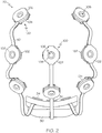
- an exemplary electrode system (10) includes a headset (20) and a control box (40).
- Headset (20) comprises a head frame (24) and a plurality of electrode modules (100). While headset (20) of the present example comprises eight electrode modules (100), it should be understood that any other suitable number of electrode modules (100) may be used. It should also be understood that the arrangement of electrode modules (100) shown in FIGS. 1-3 is merely exemplary; and that electrode modules (100) may be positioned in any other suitable arrangement. Electrode modules (100) are removably coupled with head frame (24) as will be described in greater detail below.
- head frame (24) is formed of several resilient straps (26), and electrode modules (100) are secured to head frame (24) at junctions of resilient straps (26).
- the junctions of resilient straps (26) comprise annular snap members (28), which are each open at their center.
- openings (106) of electrode modules (100) are configured to align with the open centers of corresponding snap members (28), to allow inserted sensors (200) to contact the test subject's head.
- resilient straps (26) are formed of elastic, though it should be understood that any other suitable material or combination of materials may be used.
- head frame (24) of the present example is configured to substantially encompass a test subject's head, it should also be understood that head frame (24) may have any other suitable configuration.
- head frame (24) may comprise a EzeNet® reusable head piece by HydroDot, Inc. of Westford, MA.
- a EzeNet® reusable head piece may come in various sizes and conform to the international 10/20 system of electrode placement.
- head frame (24) may be configured and/or operable in accordance with the teachings of U.S. Pub. No. 2007/0191727 , entitled “Evoked Response Testing System for Neurological Disorders," published August 16, 2007; and/or in accordance with the teachings of any other document cited herein. Indeed, various ways in which the teachings herein may be combined with the teachings of U.S. Pub. No. 2007/0191727 and/or the teachings of any other document cited herein will be apparent to those of ordinary skill in the art. Alternatively, head frame (24) may have any other suitable configuration and/or operability. Other suitable variations of head frame (24) will be apparent to those of ordinary skill in the art in view of the teachings herein.
- Electrode modules (100) are physically and communicatively coupled with each other via flexible connectors (50). Electrode modules (100) are also physically and communicatively coupled with a control box interface module (30) via flexible connectors (50). Flexible connectors (50) of the present example comprise flexible circuits, which comprise traces (not shown) formed in a flexible substrate. Alternatively, conventional wires or other conduits may be used.
- headset (20) is coupled with control box (40) via cables (42).
- control box interface module (30) includes ports (32), with which cables (42) may be coupled.
- Control box interface module (30) also includes circuitry configured to route signals between flexible connectors (50) and cables (42) via ports (32).
- Control box interface module (30) may thus provide a communicative interface between cables (42) and flexible connectors (50).
- Various suitable components that may be incorporated into control box interface module (30), as well as various suitable features/functionalities of such components, are described in the documents cited herein.
- control box interface module (30) may be constructed and operable in accordance with the headset "control module 12" teachings of U.S. Pub. No. 2007/0191727 and/or the teachings of any other document cited herein.
- Still other suitable components that may be incorporated into control box interface module (30) will be apparent to those of ordinary skill in the art in view of the teachings herein.
- control box interface module (30) also includes flanged members (34).
- Flange members (34) are configured to secure control box interface module (30) with head frame (24).
- head frame (24) may include openings that are configured to receive flanged members (34).
- control box interface module (30) may be secured to head frame (24) in a variety of other ways as will be appreciated by those of ordinary skill in the art, to the extent that control box interface module (30) is secured to head frame (24) at all.
- control box interface module (30) may simply be omitted in some versions (e.g., cables (42) couple directly to freely hanging flexible connectors (50), etc.).
- Control box (40) of the present example includes a storage medium (not shown) that is configured to store various testing protocols (e.g., ERP testing protocols, etc.); and a processor (not shown) that is configured to execute such testing via headset (20).
- control box (40) provides power and commands or other types of signals to headset (20) via cables (42) in the present example; while headset (20) transmits data or other types of signals back to control box (40) via cables (42).
- Control box (40) is also operable to store data collected during such testing, including but not limited to data obtained through electrode modules (100).
- Such power, commands, data, or other types of signals may be provided in accordance with various types of ERP testing protocols as described herein and as described in the cited documents.
- Control box (40) is configured to be coupled with a computer system (not shown) via wire and/or wirelessly.
- a computer system may transmit testing protocols, commands, or other data to control box (40).
- control box (40) may transmit commands, test results, or other data to a computer system.
- Control box (40) of the present example is also configured to be handheld.
- control box (40) may be held in the hand of the test subject who is wearing headset (40), in the hand of a clinician or nurse, or in the hand of any other person.
- control box (40) may be configured in accordance with, operable in accordance with, and/or possess any suitable features/functionalities of similar components described in any of the documents cited herein, including but not limited to U.S. Pub. No. 2007/0191727 .
- teachings herein may be incorporated into or otherwise combined with the teachings of the documents that are cited herein will be readily apparent to those of ordinary skill in the art.
- Electrode system (10) may provide communication of power, commands, data, and/or other types of signals to and/or from headset (20) wirelessly, in addition to or in lieu of having cables (22).
- electrode modules (100) of electrode system (10) are substantially identical to each other.
- the following description will therefore just describe an individual electrode module (100) as an example.
- a given electrode system (10) may have different types of electrode modules (100).
- one or more electrode modules (100) within a given electrode system (10) may have features, components, functionalities, etc., that differ from the features, components, functionalities, etc., of other electrode modules (100) within the same electrode system (10).
- Such differences among electrode modules (100) may be based on a variety of considerations, including but not limited to the location of electrode module (100) on the test subject's head or other part of the test subject's anatomy.
- electrode modules (100) may differ from each other within a given electrode system (10) will be apparent to those of ordinary skill in the art in view of the teachings herein.
- all electrode modules (100) within a given electrode system (10) may be substantially identical to each other.
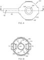
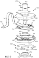
- electrode module (100) comprises an upper clamshell member (102), a lower clamshell member (104), a circuit board (130), and a conductive ring (150).
- Clamshell members (102, 104) may be formed of molded plastic and/or using any other suitable material(s) and/or process(es).
- upper clamshell member (102), lower clamshell member (104), circuit board (130), and conductive ring (150) all define a central opening (106).
- the central openings of upper clamshell member (102), lower clamshell member (104), circuit board (130), and conductive ring (150) are all configured to coaxially align when these components are assembled together to form electrode module (100), such that the assembled electrode module (100) itself defines a central opening (106).
- This central opening (106) is configured to insertingly receive a sensor (200) as will be described in greater detail below.
- these components are configured such that a portion of conductive ring (150) is exposed in the inner diameter of the central opening (106) of the assembled electrode module (100), as will also be described in greater detail below.
- upper clamshell member (102) may be secured to lower clamshell member (104) using any suitable technique or techniques, including but not limited to ultrasonic welding, snap-fitting, adhesives, fasteners, etc. While opening (106) is at the approximate center of electrode module (100) in the present example, it should be understood that opening (106) may be located off-center or otherwise relative to the remainder of electrode module (100).
- Upper clamshell member (102) of the present example presents an annular inclined surface (108) at the perimeter of opening (106). Annular inclined surface (108) is configured to facilitate insertion of sensor (200) into opening (106) as will be described in greater detail below.
- inclined surface (108) is merely optional.
- Lower clamshell member (104) of the present example comprises a first pair of upwardly extending posts (110) and a second pair of upwardly extending posts (112).
- Lower clamshell member (104) also includes an annular rim (114) at the perimeter of opening (106) and a trench (116) adjacent to annular rim (114).
- Circuit board (130) of the present example comprises a pair of openings (132) and a pair of connectors (134). As shown in FIGS. 5-6 , openings (132) of circuit board (130) are configured to align with and receive posts (110) of lower clamshell member (104). Openings (132) and posts (110) may thus assist in properly registering circuit board (130) with lower clamshell member (104) and assist in securing circuit board (130) relative to lower clamshell member (104). Of course, openings (132) and posts (110) are merely one of many different ways in which circuit board (130) may be registered and secured relative to lower clamshell member (104). Various other structures, features, techniques, etc. for registering and/or securing circuit board (130) relative to lower clamshell member (104) will be apparent to those of ordinary skill in the art in view of the teachings herein.
- Connectors (134) of circuit board (130) are configured to be physically and communicatively coupled with flexible connectors (50).
- each connector (134) has a slot that is configured to receive a free end of a corresponding flexible connector (50).
- Flexible connector (50) has an opening (52) that is configured to receive a post (112) of lower clamshell member (104).
- connector (134) may have one or more exposed/exposable electrical contacts within its slot; while the free end of flexible connector (50) may have one or more corresponding electrical contacts that are positioned to contact the one or more exposed/exposable electrical contacts within the slot of connector (134).
- Connector (134) may thus communicate power, commands, data, other signals, etc., to and/or from one or more traces of flexible connector (50).
- connectors (134) are merely optional, and connectors (134) may be modified, substituted, supplemented, or omitted as desired.
- some alternative versions omit connectors (134) entirely by forming all flexible connectors (50) and circuit boards (130) as a single, unitary rigid-flex circuit.
- a merely illustrative example of such a rigid-flex circuit is disclosed in U.S. Provisional Patent Application Serial No. 61/245,686 , entitled "Electrode System with Rigid-Flex Circuit," filed September 25, 2009. Still other suitable ways in which connectors (134) may be modified, substituted, supplemented, or omitted will be apparent to those of ordinary skill in the art in view of the teachings herein.
- electrode modules (100) are coupled via flexible connectors (50).
- different electrode modules (100) have their own dedicated traces along such flexible connectors (50).
- Dedicated traces for a given electrode module (100) may run along part of the same length of flexible connectors (50) as dedicated traces for another given electrode module (100).
- a set of dedicated traces for one electrode module (100) may be provided on one layer of flexible circuitry in a given flexible connector (50); while a set of dedicated traces for another electrode module (100) may be provided on another layer of flexible circuitry on the same flexible connector (50), with both layers extending along a common length of the flexible circuitry of the same flexible connector (50).
- dedicated traces for one electrode module (100) may be provided on the same layer of flexible circuitry as dedicated traces for another electrode module (100), such that the separate sets of traces are geometrically parallel on a common layer.
- different electrode modules (100) may share one or more common traces in a given flexible connector (50).
- one or more traces in flexible circuitry of flexible connectors (50) may be used for bus transmissions, such that information associated with different electrode modules (100) may be combined onto a bus and communicated along one or more nondedicated traces that are in communication with more than one electrode module (100).
- traces or other communication features may be used, provided, arranged, etc., will be apparent to those of ordinary skill in the art in view of the teachings herein.
- Circuit board (130) in each electrode module (100) of the present example also comprises sensing circuitry (not shown), which includes an amplifier among other components.
- sensing circuitry is in communication with connectors (134) of circuit board (130), such that the sensing circuitry may communicate with the one or more traces of flexible connectors (50).
- the sensing circuitry of circuit board (130) including an amplifier in the present example it should be understood that electrode modules (100) are thus active.
- Such sensing circuitry may be configured and/or operable in accordance with the teachings of U.S. Pub. No.
- circuit board (130) may have any other suitable configuration and/or operability.
- some versions of circuit board (130) may lack an amplifier, such that electrode modules (100) are not active.
- circuit board (130) may be configured, including but not limited to various forms and components of sensing circuitry, will be apparent to those of ordinary skill in the art in view of the teachings herein.
- conductive ring (150) comprises a tail portion (152) that extends radially outwardly.
- Conductive ring (150) is configured to rest on annular rim (114) of lower clamshell member (104), with tail portion (152) projecting through trench (116) of lower clamshell member (104). Accordingly, annular rim (114), trench (116), and tail portion (152) cooperate to assist in properly registering conductive ring (150) with lower clamshell member (104) and assist in securing conductive ring (150) relative to lower clamshell member (104).
- these features are just an example, and various other structures, features, techniques, etc.
- upper clamshell member (102) is positionable over conductive ring (150) to further secure conductive ring (150) in place by "sandwiching" conductive ring (150) between clamshell members (102, 104).
- a portion of conductive ring (150) is still exposed in the inner diameter of the central opening (106) of the assembled electrode module (100) (e.g., when upper clamshell member (102) is secured to lower clamshell member (104), etc.).
- Conductive ring (150) is also communicatively coupled with the sensing circuitry of circuit board (130) (e.g., through contact via tail portion (152), etc.).
- conductive ring (150) is configured to communicate ERP signals to the sensing circuitry of circuit board (130) as will be described in greater detail below.
- Electrode modules (100) may be coupled with head frame (24) in a variety of ways.
- electrode modules (100) are coupled with head frame (24) through snap fittings at snap members (28) of head frame (24).
- each electrode module (100) of the present example is provided with a snap adapter (170).
- Each snap adapter (170) comprises an upper flange (172), a lower flange (174), and a cylindraceous portion (176) extending vertically between upper and lower flanges (172, 174).
- Lower clamshell member (104) includes an annular recess (118) that is configured to snappingly receive upper flange (172) of snap adapter (170) as shown in FIG. 7 .
- Snap adapter (170) thus couples with electrode module (100) through a snap fitting in the present example, though it should be understood that any other suitable features, components, techniques, etc., may be used to secure a snap adapter (170) with an electrode module (100).
- electrode module (100) may have an integral or unitary snap adapter, or may couple with head frame (24) in some other way.
- a pad (160) is secured to each snap adapter (170).
- Each pad (160) has a plurality of outwardly extending tabs (162) and is relatively soft.
- the configuration of pad (160) may reduce discomfort to a test subject when a clinician manipulates electrode modules (100) while electrode modules (100) are on the test subject's head.
- Pad (160) is configured to fit about cylindraceous portion (176) of snap adapter (170). As shown in FIG. 7 , pad (160) is "sandwiched" between the lower surface of lower clamshell member (104) and the upper surface of lower flange (174).
- pad (160) may be coupled with electrode module (100) in a variety of other ways.
- pad (160) may be secured to electrode module by one or more clips, hook and loop fasteners, adhesives, etc.
- pad (160) may be omitted entirely.
- snap member (28) of head frame (24) may be positioned about cylindraceous portion (176) of snap adapter (170).
- Snap member (28) may thus be “sandwiched” between the lower surface of lower clamshell member (104) and the upper surface of lower flange (174), similar to pad (160) in FIG. 7 .
- snap adapter (170) snappingly engages with snap member (28) (e.g., such that at least a portion of snap member (28) is positioned below lower flange (174)).
- snap adapter (170) may simply be omitted.
- snap member (28) may itself snapplingly engage with lower clamshell member (104).
- snap member (28) may include an outwardly extending annular flange that is snappingly received in annular recess (188) of lower clamshell member (104).
- electrode modules (100) may couple directly with head frame (24), such that no snap fittings are used to couple electrode modules (100) with head frame (24).
- electrode modules (100) may be coupled with head frame (24) by one or more clips, hook and loop fasteners, adhesives, etc.
- electrode modules (100) are removably coupled with head frame (24) in the present example, electrode modules (100) may be permanently affixed to head frame (24) in some other versions.
- electrode system (10) of the present example further includes removable sensors (200).
- Removable sensors (200) of this example each comprise an insulating upper portion (202), an electrolytic hydrogel lower portion (204), and a conductive center portion (206) positioned between upper and lower portions (202, 204).
- Conductive center portion (206) comprises a plurality of outwardly extending conductive tabs (208).
- Each sensor (200) is configured to be inserted in the central opening (106) of a corresponding electrode module (100) and fit snugly therein.
- each electrode module (100) in an electrode system (10) has an associated removable sensor (200) inserted therein; though some electrode modules (100) may lack an associated electrode module (100) in some settings.
- Inclined surface (108) of upper clamshell member (102) at the perimeter of opening (106) may facilitate insertion of sensor (200) in opening (106), such as by guiding sensor (200) into opening.
- inclined surface (108) is merely optional, and may be modified, substituted, supplemented, or omitted as desired.
- removable sensor (200) When removable sensor (200) is inserted in electrode module (100), and the corresponding head frame (24) is secured to a test subject's head, removable sensor (200) is configured such that electrolytic hydrogel lower portion (204) contacts the scalp of the test subject.
- sensor (200) may have a height such that hydrogel lower portion (204) protrudes below lower flange (174) of snap adapter (170) while insulating upper portion (202) is vertically positioned at or near inclined surface (108) of upper clamshell member (102).
- sensors (200) may have any other suitable dimensions.
- the associated electrolytic hydrogel lower portion (204) may contact some other part of the test subject's head or body.
- hydrogel lower portion (204) may simply contact the hair on the test subject's head; and electrode system (10) may still work properly even if sensors (200) only contact the hair on the test subject's head without necessarily contacting the skin on the test patient's scalp. Due to the electrolytic properties of the electrolytic hydrogel lower portion (204), electrolytic hydrogel lower portion (204) may pick up voltages or signals (e.g., ERP signals, etc.) from the test subject's (e.g., patient's) skin. Electrolytic hydrogel lower portion (204) may collect data without needing to be pasted or glued to the test subject's head, as the hydrogel itself may sufficiently adhere to the subject's head while also allowing removable sensor (200) to be pulled away from the subject's head with relative ease.
- voltages or signals e.g., ERP signals, etc.
- tabs (208) of the present example are formed as unitary extensions of a conductive member (206) that is disposed between insulating upper portion (202) and electrolytic hydrogel lower portion (204).
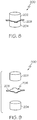
- Conductive member (206) and tabs (208) are configured such that tabs (208) are resiliently biased to assume radially outwardly extending orientations, as shown in FIGS. 5 and 8-9 .
- tabs (208) contact conductive ring (150), which is exposed in the inner diameter of opening (106) as shown in FIG. 7 .
- tabs (208) may resiliently bear against conductive ring (150) when sensor (200) is inserted in opening (106).
- Such contact between tabs (208) and conductive ring (150) may provide a path for communication from conductive member (206) to conductive ring (150) as described in greater detail below.
- elastomeric properties or other properties of insulating upper portion (202) and/or hydrogel lower portion (204) may help retain sensor (200) in opening (106) of electrode module.
- sensor (200) may be oversized relative to opening (106), such that sensor (200) is snugly or interferingly fit in opening (106). Other ways in which sensor (200) may be substantially retained in opening (106) will be apparent to those of ordinary skill in the art in view of the teachings herein.
- Conductive member (206) and tabs (208) may be formed of silver-silver chloride and/or any other suitable material or materials.
- Conductive ring (150) may also be formed of silver-silver chloride and/or any other suitable material or materials.
- tabs (208) With tabs (208) being in contact with conductive ring (150) when sensor (100) is inserted in opening (106) of electrode module (100), tabs (208) may thus communicate voltages or signals picked up by electrolytic hydrogel lower portion (204) to conductive ring (150), which may in turn communicate such voltages or signals to sensing circuitry of circuit board (130).
- An amplifier on circuit board (130) (or elsewhere) may amplify the signal, and other components within the sensing circuitry may perform other processing of the signal if desired, and the signal may then be communicated away from electrode module (100) via flexible circuitry in one or more flexible connectors (50). The signals may thus ultimately be communicated to control box interface module (30) via flexible connectors (50) and then on to control box (40) via cable (42).
- removable sensors (200) comprise HydroDot® Disposable EEG Electrodes or HydroDot® Biosensors by HydroDot, Inc. of Westford, MA.
- HydroDot® Disposable EEG Electrode Application System are discussed in U.S. Patent No. 5,479,934 , entitled “EEG Headpiece with Disposable Electrodes and Apparatus and System and Method for Use Therewith," issued January 2, 1996.
- various components of electrode system (10), including but not limited to removable sensors (200) may be configured, modified, and/or operable in accordance with any suitable teachings in U.S. Patent No. 5,479,934 .
- teachings herein may be combined with the teachings of U.S. Patent No.
- electrode modules (100) may be configured such that they have an electrical interface with the test subject's head and/or some other type of interface with the test subject's head and/or other body part through an injectable gel or in any other suitable fashion.
- sensors (200) of the present example have a substantially cylindraceous shape
- sensors (200) may alternatively have any other shape.
- sensors (200) may have a cubical shape, a right cuboidal shape, a conical shape, a frustoconical shape, a pyramidal shape, a spherical shape, and/or any other suitable shape.
- conductive rings (150) of the present example have a substantially circular shape
- conductive rings (150) may alternatively have any other shape.
- conductive rings (150) may have a square shape, a rectangular shape, a triangular shape, and/or any other suitable shape. Still other suitable configurations of and relationships between sensors (200) and conductive rings (150) will be apparent to those of ordinary skill in the art in view of the teachings herein.
- electrode system (10) comprises eight electrode modules (100). As another merely illustrative example, electrode system (10) may comprise twenty three electrode modules (100). Of course, electrode system (10) may alternatively comprise any other suitable number of electrode modules (100). It should also be understood that electrode modules (100) may be arranged in a variety of ways. By way of example only, various suitable arrangements are disclosed in the documents that are cited herein.
- Electrodes system (10) may be processed in accordance with the teachings of U.S. Pub. No. 2008/0208072 , entitled “Biopotential Waveform Data Fusion Analysis and Classification Method," published August 28, 2008. Alternatively, signals obtained using electrode system (10) may be processed in any other suitable fashion.
- various suitable ways in which electrode system (10) may be used are disclosed in the various documents cited herein. Still other suitable ways in which electrode system (10) may be used will be apparent to those of ordinary skill in the art in view of the teachings herein. It is contemplated that the teachings herein may be incorporated into or otherwise combined with the systems, components, and methods disclosed in the documents cited herein, in numerous ways. Suitable ways in which the teachings herein may be incorporated into or otherwise combined with the teachings of the documents cited herein will be apparent to those of ordinary skill in the art in view of the teachings herein.
Landscapes
- Health & Medical Sciences (AREA)
- Life Sciences & Earth Sciences (AREA)
- Medical Informatics (AREA)
- Biophysics (AREA)
- Pathology (AREA)
- Engineering & Computer Science (AREA)
- Biomedical Technology (AREA)
- Heart & Thoracic Surgery (AREA)
- Physics & Mathematics (AREA)
- Molecular Biology (AREA)
- Surgery (AREA)
- Animal Behavior & Ethology (AREA)
- General Health & Medical Sciences (AREA)
- Public Health (AREA)
- Veterinary Medicine (AREA)
- Psychiatry (AREA)
- Psychology (AREA)
- Measurement And Recording Of Electrical Phenomena And Electrical Characteristics Of The Living Body (AREA)
Claims (12)
- Elektrodensystem, Folgendes umfassend:a) mehrere Elektrodenmodule (100);b) mehrere biegsame Verbindungsglieder (50), die mit den mehreren Elektrodenmodulen (100) verbunden sind, wobei die biegsamen Verbindungsglieder (50) biegsame Schaltungstechnik umfassen, die dafür eingerichtet ist, Signale von den Elektrodenmodulen (100) zu übertragen, wobei die biegsame Schaltungstechnik Bahnen umfasst, die auf einem biegsamen Substrat ausgebildet sind; undc) mehrere Sensoren (200), wobei jeder Sensor (200) von den mehreren Sensoren (200) dafür eingerichtet ist, abnehmbar mit einem zugehörigen von den mehreren Elektrodenmodulen (100) gekoppelt zu werden, wobei die mehreren Sensoren (200) dafür eingerichtet sind, evozierte Antwortpotentiale von einer Versuchsperson zu erfassen und wobei jeder Sensor (200) außerdem dafür eingerichtet ist, erfasste evozierte Antwortpotentiale an das zugehörige Elektrodenmodul (100) zu übertragen,wobei
jedes Elektrodenmodul (100) von den mehreren Elektrodenmodulen (100) eine im Wesentlichen mittige Öffnung (106) definiert;
jeder Sensor (200) in der im Wesentlichen mittigen Öffnung (106) des zugehörigen Elektrodenmoduls (100) positioniert ist; und
dadurch gekennzeichnet, dass
jeder Sensor (200) wenigstens ein sich nach außen erstreckendes leitendes Aufhängerelement (208) umfasst,
wobei das sich nach außen erstreckende leitende Aufhängerelement (208) dafür eingerichtet ist, mit einem leitenden Ring (150) des zugehörigen Elektrodenmoduls (100) Kontakt herzustellen. - Elektrodensystem nach Anspruch 1, wobei jedes Elektrodenmodul (100) ein Gehäuse umfasst, das die im Wesentlichen mittige Öffnung (106) definiert, und wobei der leitende Ring (150) jedes Elektrodenmoduls (100) an einem Innendurchmesser der im Wesentlichen mittigen Öffnung (106), die durch das Gehäuse des zugehörigen Elektrodenmoduls (100) definiert ist, wenigstens teilweise offen liegt.
- Elektrodensystem nach Anspruch 1, wobei jedes der Elektrodenmodule (100) ein oberes Schalenhalbelement (102), ein unteres Schalenhalbelement (104) und eine Schaltungsplatine (130) umfasst, wobei die Schaltungsplatine (130) zwischen dem oberen Schalenhalbelement (102) und dem unteren Schalenhalbelement (104) angeordnet ist und wobei das obere Schalenhalbelement (102) und das untere Schalenhalbelement (104) miteinander verbunden sind.
- Elektrodensystem nach Anspruch 3, wobei die Schaltungsplatine (130) jedes Elektrodenmoduls (100) außerdem eine Steckbuchse umfasst und wobei ein Teil jedes biegsamen Verbindungsglieds (50) in die Steckbuchse eines zugehörigen von den Elektrodenmodulen (100) eingeführt ist, um eine Kommunikation zwischen der Schaltungsplatine (130) jedes Elektrodenmoduls (100) und der biegsamen Schaltungstechnik eines zugehörigen von den biegsamen Verbindungsgliedern (50) bereitzustellen.
- Elektrodensystem nach Anspruch 1, wobei jedes Elektrodenmodul (100) einen zugehörigen Verstärker umfasst.
- Elektrodensystem nach Anspruch 1, das außerdem ein Kopfgestell (24) umfasst, das dafür eingerichtet ist, auf den Kopf einer Versuchsperson zu passen, wobei die Elektrodenmodule (100) abnehmbar mit dem Kopfgestell (24) verbunden sind.
- Elektrodensystem nach Anspruch 6, wobei die Elektrodenmodule (100) mit dem Kopfgestell (24) durch Schnapphaken verbunden sind.
- Elektrodensystem nach Anspruch 6, wobei das Kopfgestell (24) mehrere elastische Elemente umfasst.
- Elektrodensystem nach Anspruch 1, das außerdem eine Steuerungsbox (40) umfasst, die in Kommunikation mit den Elektrodenmodulen (100) ist, wobei die Steuerungsbox (40) ein Speichermedium umfasst, das Protokolle für Tests mit evozierten Antworten speichert, sowie einen Prozessor, der dafür eingerichtet ist, gemäß den gespeicherten Protokollen für Tests mit evozierten Antworten Tests mit evozierten Antworten über die Elektrodenmodule (100) auszuführen.
- Elektrodensystem nach Anspruch 9, wobei das Speichermedium der Steuerungsbox (40) außerdem dafür eingerichtet ist, Ergebnisse der Tests mit evozierten Antworten zu speichern.
- Elektrodensystem nach Anspruch 1, wobei jeder Sensor (200) von den mehreren Sensoren (200) einen isolierenden oberen Abschnitt (202), einen unteren Abschnitt (204) mit elektrolytischem Hydrogel und einen leitenden Abschnitt zwischen dem oberen und unteren Abschnitt (202, 204) umfasst, wobei der leitende Abschnitt mehrere leitende Aufhängerelemente (208) umfasst, die sich relativ zum oberen und unteren Abschnitt (202, 204) nach außen erstrecken.
- Verfahren zum Vorbereiten eines Elektrodensystems, wobei das Elektrodensystem ein Kopfgestell (24); mehrere Elektrodenmodule (100), die mit dem Kopfgestell (24) verbunden sind; und mehrere Sensoren (200); umfasst, wobei jedes Elektrodenmodul (100) eine zugehörige Öffnung definiert; wobei jedes Elektrodenmodul (100) einen leitenden Ring (150) innerhalb der Öffnung des zugehörigen Elektrodenmoduls (100) hat; wobei von den Sensoren (200) jeder einen oberen Abschnitt, einen unteren Abschnitt und sich nach außen erstreckende leitende Aufhängerelemente (208) hat,
wobei das Verfahren Folgendes umfasst:a) Positionieren des Kopfgestells (24) um den Kopf einer Versuchsperson herum, derart, dass die Elektrodenmodule (100) um den Kopf der Versuchsperson herum positioniert sind;b) Einsetzen der Sensoren (200) in die Öffnungen der Elektrodenmodule (100), wobei der Vorgang des Einsetzens der Sensoren (200) dazu führt, dass die unteren Abschnitte der Sensoren (200) in Kontakt mit dem Kopf der Versuchsperson kommen und die Aufhängerelemente (208) der Sensoren Kontakt mit den leitenden Ringen (150) der Elektrodenmodule (100) herstellen;c) Ausführen eines Tests mit evozierten Antwortpotentialen an der Versuchsperson; undd) Erfassen von Potentialen, die von der Versuchsperson in Reaktion auf den Test mit evozierten Antwortpotentialen evoziert werden, wobei die Potentiale unter Verwendung der eingesetzten Sensoren (200) erfasst werden.
Applications Claiming Priority (2)
| Application Number | Priority Date | Filing Date | Title |
|---|---|---|---|
| US11471508P | 2008-11-14 | 2008-11-14 | |
| PCT/US2009/064320 WO2010056947A1 (en) | 2008-11-14 | 2009-11-13 | Electrode system |
Publications (3)
| Publication Number | Publication Date |
|---|---|
| EP2344029A1 EP2344029A1 (de) | 2011-07-20 |
| EP2344029A4 EP2344029A4 (de) | 2015-03-04 |
| EP2344029B1 true EP2344029B1 (de) | 2017-09-27 |
Family
ID=42170351
Family Applications (1)
| Application Number | Title | Priority Date | Filing Date |
|---|---|---|---|
| EP09826806.3A Active EP2344029B1 (de) | 2008-11-14 | 2009-11-13 | Elektrodensystem |
Country Status (5)
| Country | Link |
|---|---|
| US (2) | US8364238B2 (de) |
| EP (1) | EP2344029B1 (de) |
| JP (1) | JP5547207B2 (de) |
| AU (1) | AU2009313957B2 (de) |
| WO (1) | WO2010056947A1 (de) |
Families Citing this family (35)
| Publication number | Priority date | Publication date | Assignee | Title |
|---|---|---|---|---|
| AU2009313957B2 (en) * | 2008-11-14 | 2014-10-23 | Neuronetrix Solutions, Llc | Electrode system |
| AU2010298299B2 (en) * | 2009-09-25 | 2014-11-20 | Neuronetrix Solutions, Llc | Electrode system with rigid-flex circuit |
| CN102781322B (zh) | 2010-06-11 | 2015-02-25 | 松下电器产业株式会社 | 语音听取的评价系统、及方法 |
| CN102781321B (zh) | 2010-06-11 | 2015-04-08 | 松下电器产业株式会社 | 听力判定系统及其方法 |
| CA2810677A1 (en) * | 2010-09-10 | 2012-03-15 | Neuronetrix Solutions, Llc | Electrode system with in-band impedance detection |
| AU2011301761B2 (en) * | 2010-09-13 | 2013-05-09 | Hear Ip Pty Ltd | A signal processing device for use in electroencephalography and a cable system incorporating the device |
| JP5803186B2 (ja) * | 2011-03-23 | 2015-11-04 | ソニー株式会社 | 生体信号検出電極及び生体信号検出装置 |
| KR101347606B1 (ko) * | 2011-11-25 | 2014-01-07 | 한국과학기술연구원 | 뇌전도를 이용한 로봇기반 자폐진단 장치 및 그 방법 |
| US11172859B2 (en) | 2014-01-28 | 2021-11-16 | Medibotics | Wearable brain activity device with auditory interface |
| US10234942B2 (en) | 2014-01-28 | 2019-03-19 | Medibotics Llc | Wearable and mobile brain computer interface (BCI) device and method |
| US10130277B2 (en) | 2014-01-28 | 2018-11-20 | Medibotics Llc | Willpower glasses (TM)—a wearable food consumption monitor |
| US9814426B2 (en) * | 2012-06-14 | 2017-11-14 | Medibotics Llc | Mobile wearable electromagnetic brain activity monitor |
| US11662819B2 (en) | 2015-05-12 | 2023-05-30 | Medibotics | Method for interpreting a word, phrase, and/or command from electromagnetic brain activity |
| US8989835B2 (en) | 2012-08-17 | 2015-03-24 | The Nielsen Company (Us), Llc | Systems and methods to gather and analyze electroencephalographic data |
| USD753833S1 (en) * | 2012-12-27 | 2016-04-12 | Neuroelectrics Barcelona S.L. | Electrode cap |
| US9320450B2 (en) | 2013-03-14 | 2016-04-26 | The Nielsen Company (Us), Llc | Methods and apparatus to gather and analyze electroencephalographic data |
| US9622702B2 (en) | 2014-04-03 | 2017-04-18 | The Nielsen Company (Us), Llc | Methods and apparatus to gather and analyze electroencephalographic data |
| USD754873S1 (en) * | 2014-07-04 | 2016-04-26 | Christoph Guger | Sensor cap |
| US10575741B2 (en) * | 2014-08-18 | 2020-03-03 | Samsung Electronics Co., Ltd | Wearable biometric information measurement device |
| USD759803S1 (en) * | 2014-10-28 | 2016-06-21 | Highland Instruments, Inc. | Adjustable headpiece with anatomical markers |
| JP2016179006A (ja) * | 2015-03-24 | 2016-10-13 | タイオー株式会社 | 脳波計測装置 |
| US11311228B1 (en) | 2015-06-02 | 2022-04-26 | WAVi Co. | Multi-function apparatus, systems and methods for receiving signals from a human subject's head |
| US9854988B2 (en) * | 2015-06-02 | 2018-01-02 | Wavi Co | Apparatus, systems and methods for receiving signals from a human subject's brain |
| JP6590277B2 (ja) * | 2015-08-07 | 2019-10-16 | 国立大学法人 奈良先端科学技術大学院大学 | 生体情報取得装置 |
| JP6855045B2 (ja) * | 2015-11-30 | 2021-04-07 | 東海光学株式会社 | 脳活動計測用電極、その電極を使用した頭部装着装置及び脳活動計測システム |
| US10506974B2 (en) | 2016-03-14 | 2019-12-17 | The Nielsen Company (Us), Llc | Headsets and electrodes for gathering electroencephalographic data |
| US9735893B1 (en) | 2016-07-21 | 2017-08-15 | Intel Corporation | Patch system for in-situ therapeutic treatment |
| CN107802263A (zh) * | 2016-09-08 | 2018-03-16 | 候俊英 | 一种基于脑电生理信号的可穿戴声音反馈系统 |
| US10039186B2 (en) | 2016-09-16 | 2018-07-31 | Intel Corporation | Stretchable and flexible electrical substrate interconnections |
| CN109310344B (zh) * | 2017-02-22 | 2022-05-17 | 玫莫里Md股份有限公司 | 用于进行脑电图的装置和方法 |
| EP3703523B1 (de) * | 2017-12-01 | 2024-02-07 | Zeto, Inc. | Kopfhörer und elektroden zur erfassung des bioelektrischen potentials und verfahren zu deren betrieb |
| USD879306S1 (en) * | 2018-02-09 | 2020-03-24 | Bioserenity | Set of T-shirt and cap with sensors |
| US11647956B2 (en) * | 2018-03-19 | 2023-05-16 | Neurofeedback-Partner GmbH | Electroencephalogram system and method |
| US11642081B2 (en) * | 2019-02-01 | 2023-05-09 | X Development Llc | Electrode headset |
| US11583231B2 (en) * | 2019-03-06 | 2023-02-21 | X Development Llc | Adjustable electrode headset |
Family Cites Families (36)
| Publication number | Priority date | Publication date | Assignee | Title |
|---|---|---|---|---|
| US3762420A (en) * | 1971-06-03 | 1973-10-02 | Academic Associates Inc | Defibrillation electrode |
| US5038782A (en) * | 1986-12-16 | 1991-08-13 | Sam Technology, Inc. | Electrode system for brain wave detection |
| AT398041B (de) | 1990-02-09 | 1994-08-25 | Head Sport Ag | Kunststoff-schalenski |
| US5211174A (en) | 1990-09-14 | 1993-05-18 | Physiometrix, Inc. | Low impedance, low durometer, dry conforming contact element |
| US5179570A (en) | 1991-07-19 | 1993-01-12 | Imran Mir A | Direct sequence spread spectrum communication system with self-synchronizing correlator and method |
| US5452718A (en) | 1991-11-08 | 1995-09-26 | Clare; Christopher R. | Electrode construction, assembly thereof, package therefor and method |
| AU667199B2 (en) * | 1991-11-08 | 1996-03-14 | Physiometrix, Inc. | EEG headpiece with disposable electrodes and apparatus and system and method for use therewith |
| US5238005A (en) | 1991-11-18 | 1993-08-24 | Intelliwire, Inc. | Steerable catheter guidewire |
| US5327888A (en) | 1992-06-05 | 1994-07-12 | Physiometrix, Inc. | Precordial electrode strip and apparatus and method using the same |
| US5295482A (en) | 1992-10-22 | 1994-03-22 | Physiometrix, Inc. | Large surface area electrode |
| US20010011224A1 (en) * | 1995-06-07 | 2001-08-02 | Stephen James Brown | Modular microprocessor-based health monitoring system |
| US5289822A (en) | 1992-12-01 | 1994-03-01 | Physiometrix, Inc. | Electrode for reducing the surface resistivity of skin and method |
| US6067467A (en) | 1994-02-07 | 2000-05-23 | New York University | EEG operative and post-operative patient monitoring method |
| US5540722A (en) | 1994-05-16 | 1996-07-30 | Physiometrix, Inc. | Switch apparatus and method for switching between multiple electrodes for diagnostic and therapeutic procedures |
| US5596038A (en) | 1994-05-16 | 1997-01-21 | Physiometrix, Inc. | Hydrogel having a silicon-based crosslinker for biosensors and electrodes |
| US5520683A (en) | 1994-05-16 | 1996-05-28 | Physiometrix, Inc. | Medical electrode and method |
| US6128521A (en) | 1998-07-10 | 2000-10-03 | Physiometrix, Inc. | Self adjusting headgear appliance using reservoir electrodes |
| US6301493B1 (en) | 1999-07-10 | 2001-10-09 | Physiometrix, Inc. | Reservoir electrodes for electroencephalograph headgear appliance |
| AU1241501A (en) | 1999-10-27 | 2001-05-08 | Physiometrix, Inc. | Module for acquiring electroencephalograph signals from a patient |
| WO2001030232A2 (en) | 1999-10-27 | 2001-05-03 | Physiometrix, Inc. | Low cost high performance patient interface for electroencephalograph signals |
| US6317627B1 (en) | 1999-11-02 | 2001-11-13 | Physiometrix, Inc. | Anesthesia monitoring system based on electroencephalographic signals |
| WO2004002301A2 (en) | 2001-07-17 | 2004-01-08 | Gmp Wireless Medicine, Inc. | Wireless ecg system |
| US7933642B2 (en) * | 2001-07-17 | 2011-04-26 | Rud Istvan | Wireless ECG system |
| MXPA04012556A (es) * | 2002-07-01 | 2005-10-19 | Gmp Wireless Medicine Inc | Sistema electrocardiografico inalambrico. |
| EP1638458B1 (de) * | 2003-06-19 | 2011-11-02 | Neuronetrix Solutions, LLC | Vorrichtung und verfahren für ein automatisches eeg-system für auditorisch evozierte antworten |
| US20050215916A1 (en) * | 2004-03-29 | 2005-09-29 | Fadem Kalford C | Active, multiplexed digital electrodes for EEG, ECG and EMG applications |
| EP2260760B1 (de) * | 2004-06-18 | 2014-08-27 | Neuronetrix Solutions, LLC | Testsystem für evozierte Potentiale für neurologische Erkrankungen |
| US20050280531A1 (en) * | 2004-06-18 | 2005-12-22 | Fadem Kalford C | Device and method for transmitting physiologic data |
| US20180146879A9 (en) * | 2004-08-30 | 2018-05-31 | Kalford C. Fadem | Biopotential Waveform Data Fusion Analysis and Classification Method |
| DE102004063249A1 (de) | 2004-12-23 | 2006-07-13 | Fraunhofer-Gesellschaft zur Förderung der angewandten Forschung e.V. | Sensorsystem und Verfahren zur kapazitiven Messung elektromagnetischer Signale biologischen Ursprungs |
| US7715894B2 (en) * | 2005-11-10 | 2010-05-11 | Conopco, Inc. | Apparatus and method for acquiring a signal |
| US20070225585A1 (en) * | 2006-03-22 | 2007-09-27 | Washbon Lori A | Headset for electrodes |
| US7616980B2 (en) * | 2006-05-08 | 2009-11-10 | Tyco Healthcare Group Lp | Radial electrode array |
| US8449469B2 (en) | 2006-11-10 | 2013-05-28 | Sotera Wireless, Inc. | Two-part patch sensor for monitoring vital signs |
| EP2211712B1 (de) | 2007-11-06 | 2016-05-04 | Bio-signal Group Corp. | Vorrichtung und verfahren zur durchführung einer elektroenzephalografie |
| AU2009313957B2 (en) * | 2008-11-14 | 2014-10-23 | Neuronetrix Solutions, Llc | Electrode system |
-
2009
- 2009-11-13 AU AU2009313957A patent/AU2009313957B2/en active Active
- 2009-11-13 JP JP2011536495A patent/JP5547207B2/ja not_active Expired - Fee Related
- 2009-11-13 US US12/617,786 patent/US8364238B2/en active Active
- 2009-11-13 WO PCT/US2009/064320 patent/WO2010056947A1/en active Application Filing
- 2009-11-13 EP EP09826806.3A patent/EP2344029B1/de active Active
-
2012
- 2012-12-21 US US13/723,880 patent/US8838198B2/en active Active
Non-Patent Citations (1)
| Title |
|---|
| None * |
Also Published As
| Publication number | Publication date |
|---|---|
| US20100125190A1 (en) | 2010-05-20 |
| EP2344029A4 (de) | 2015-03-04 |
| AU2009313957B2 (en) | 2014-10-23 |
| EP2344029A1 (de) | 2011-07-20 |
| US20130116531A1 (en) | 2013-05-09 |
| US8364238B2 (en) | 2013-01-29 |
| WO2010056947A1 (en) | 2010-05-20 |
| JP2012508619A (ja) | 2012-04-12 |
| AU2009313957A1 (en) | 2010-05-20 |
| US8838198B2 (en) | 2014-09-16 |
| JP5547207B2 (ja) | 2014-07-09 |
Similar Documents
| Publication | Publication Date | Title |
|---|---|---|
| EP2344029B1 (de) | Elektrodensystem | |
| US9072448B2 (en) | Electrode system with rigid-flex circuit | |
| JP2012508619A5 (de) | ||
| EP1776922B1 (de) | Biosignal-elektrode | |
| JP5124602B2 (ja) | 生体信号測定装置 | |
| EP0737438A2 (de) | Medizinische Elektrode | |
| WO2017041014A1 (en) | Electroencephalogram monitoring system and method of use of the same | |
| JP2015534495A (ja) | 監視デバイス | |
| US20190343458A1 (en) | Assembled head-mounted module for sensing brain activity and head-mounted device for sensing brain activity | |
| KR20120016474A (ko) | 생체용 전극 및 이를 포함하는 생체신호 측정장치 | |
| GB2499595A (en) | Infant EEG electrode system | |
| AU2015200129B2 (en) | Electrode system | |
| US11642081B2 (en) | Electrode headset | |
| US20220386923A1 (en) | Electrode array assembly | |
| KR101530002B1 (ko) | 생체 신호 감지 장치 | |
| CN117460455A (zh) | 心电电极贴 |
Legal Events
| Date | Code | Title | Description |
|---|---|---|---|
| PUAI | Public reference made under article 153(3) epc to a published international application that has entered the european phase |
Free format text: ORIGINAL CODE: 0009012 |
|
| 17P | Request for examination filed |
Effective date: 20110415 |
|
| AK | Designated contracting states |
Kind code of ref document: A1 Designated state(s): AT BE BG CH CY CZ DE DK EE ES FI FR GB GR HR HU IE IS IT LI LT LU LV MC MK MT NL NO PL PT RO SE SI SK SM TR |
|
| AX | Request for extension of the european patent |
Extension state: AL BA RS |
|
| DAX | Request for extension of the european patent (deleted) | ||
| A4 | Supplementary search report drawn up and despatched |
Effective date: 20150129 |
|
| RIC1 | Information provided on ipc code assigned before grant |
Ipc: A61B 5/0478 20060101AFI20150123BHEP Ipc: A61B 5/0484 20060101ALI20150123BHEP |
|
| REG | Reference to a national code |
Ref country code: DE Ref legal event code: R079 Ref document number: 602009048613 Country of ref document: DE Free format text: PREVIOUS MAIN CLASS: A61B0005040000 Ipc: A61B0005047800 |
|
| GRAP | Despatch of communication of intention to grant a patent |
Free format text: ORIGINAL CODE: EPIDOSNIGR1 |
|
| RIC1 | Information provided on ipc code assigned before grant |
Ipc: A61B 5/0484 20060101ALI20170206BHEP Ipc: A61B 5/0478 20060101AFI20170206BHEP |
|
| INTG | Intention to grant announced |
Effective date: 20170306 |
|
| GRAS | Grant fee paid |
Free format text: ORIGINAL CODE: EPIDOSNIGR3 |
|
| GRAJ | Information related to disapproval of communication of intention to grant by the applicant or resumption of examination proceedings by the epo deleted |
Free format text: ORIGINAL CODE: EPIDOSDIGR1 |
|
| GRAL | Information related to payment of fee for publishing/printing deleted |
Free format text: ORIGINAL CODE: EPIDOSDIGR3 |
|
| GRAP | Despatch of communication of intention to grant a patent |
Free format text: ORIGINAL CODE: EPIDOSNIGR1 |
|
| GRAP | Despatch of communication of intention to grant a patent |
Free format text: ORIGINAL CODE: EPIDOSNIGR1 |
|
| INTC | Intention to grant announced (deleted) | ||
| INTG | Intention to grant announced |
Effective date: 20170721 |
|
| GRAA | (expected) grant |
Free format text: ORIGINAL CODE: 0009210 |
|
| AK | Designated contracting states |
Kind code of ref document: B1 Designated state(s): AT BE BG CH CY CZ DE DK EE ES FI FR GB GR HR HU IE IS IT LI LT LU LV MC MK MT NL NO PL PT RO SE SI SK SM TR |
|
| REG | Reference to a national code |
Ref country code: GB Ref legal event code: FG4D |
|
| REG | Reference to a national code |
Ref country code: CH Ref legal event code: EP |
|
| REG | Reference to a national code |
Ref country code: AT Ref legal event code: REF Ref document number: 931222 Country of ref document: AT Kind code of ref document: T Effective date: 20171015 |
|
| REG | Reference to a national code |
Ref country code: IE Ref legal event code: FG4D |
|
| REG | Reference to a national code |
Ref country code: NL Ref legal event code: FP |
|
| REG | Reference to a national code |
Ref country code: DE Ref legal event code: R096 Ref document number: 602009048613 Country of ref document: DE |
|
| REG | Reference to a national code |
Ref country code: FR Ref legal event code: PLFP Year of fee payment: 9 |
|
| PG25 | Lapsed in a contracting state [announced via postgrant information from national office to epo] |
Ref country code: HR Free format text: LAPSE BECAUSE OF FAILURE TO SUBMIT A TRANSLATION OF THE DESCRIPTION OR TO PAY THE FEE WITHIN THE PRESCRIBED TIME-LIMIT Effective date: 20170927 Ref country code: SE Free format text: LAPSE BECAUSE OF FAILURE TO SUBMIT A TRANSLATION OF THE DESCRIPTION OR TO PAY THE FEE WITHIN THE PRESCRIBED TIME-LIMIT Effective date: 20170927 Ref country code: FI Free format text: LAPSE BECAUSE OF FAILURE TO SUBMIT A TRANSLATION OF THE DESCRIPTION OR TO PAY THE FEE WITHIN THE PRESCRIBED TIME-LIMIT Effective date: 20170927 Ref country code: NO Free format text: LAPSE BECAUSE OF FAILURE TO SUBMIT A TRANSLATION OF THE DESCRIPTION OR TO PAY THE FEE WITHIN THE PRESCRIBED TIME-LIMIT Effective date: 20171227 Ref country code: LT Free format text: LAPSE BECAUSE OF FAILURE TO SUBMIT A TRANSLATION OF THE DESCRIPTION OR TO PAY THE FEE WITHIN THE PRESCRIBED TIME-LIMIT Effective date: 20170927 |
|
| REG | Reference to a national code |
Ref country code: LT Ref legal event code: MG4D |
|
| REG | Reference to a national code |
Ref country code: AT Ref legal event code: MK05 Ref document number: 931222 Country of ref document: AT Kind code of ref document: T Effective date: 20170927 |
|
| PG25 | Lapsed in a contracting state [announced via postgrant information from national office to epo] |
Ref country code: BG Free format text: LAPSE BECAUSE OF FAILURE TO SUBMIT A TRANSLATION OF THE DESCRIPTION OR TO PAY THE FEE WITHIN THE PRESCRIBED TIME-LIMIT Effective date: 20171227 Ref country code: LV Free format text: LAPSE BECAUSE OF FAILURE TO SUBMIT A TRANSLATION OF THE DESCRIPTION OR TO PAY THE FEE WITHIN THE PRESCRIBED TIME-LIMIT Effective date: 20170927 Ref country code: GR Free format text: LAPSE BECAUSE OF FAILURE TO SUBMIT A TRANSLATION OF THE DESCRIPTION OR TO PAY THE FEE WITHIN THE PRESCRIBED TIME-LIMIT Effective date: 20171228 |
|
| PG25 | Lapsed in a contracting state [announced via postgrant information from national office to epo] |
Ref country code: ES Free format text: LAPSE BECAUSE OF FAILURE TO SUBMIT A TRANSLATION OF THE DESCRIPTION OR TO PAY THE FEE WITHIN THE PRESCRIBED TIME-LIMIT Effective date: 20170927 Ref country code: CZ Free format text: LAPSE BECAUSE OF FAILURE TO SUBMIT A TRANSLATION OF THE DESCRIPTION OR TO PAY THE FEE WITHIN THE PRESCRIBED TIME-LIMIT Effective date: 20170927 Ref country code: RO Free format text: LAPSE BECAUSE OF FAILURE TO SUBMIT A TRANSLATION OF THE DESCRIPTION OR TO PAY THE FEE WITHIN THE PRESCRIBED TIME-LIMIT Effective date: 20170927 |
|
| PG25 | Lapsed in a contracting state [announced via postgrant information from national office to epo] |
Ref country code: IS Free format text: LAPSE BECAUSE OF FAILURE TO SUBMIT A TRANSLATION OF THE DESCRIPTION OR TO PAY THE FEE WITHIN THE PRESCRIBED TIME-LIMIT Effective date: 20180127 Ref country code: SK Free format text: LAPSE BECAUSE OF FAILURE TO SUBMIT A TRANSLATION OF THE DESCRIPTION OR TO PAY THE FEE WITHIN THE PRESCRIBED TIME-LIMIT Effective date: 20170927 Ref country code: EE Free format text: LAPSE BECAUSE OF FAILURE TO SUBMIT A TRANSLATION OF THE DESCRIPTION OR TO PAY THE FEE WITHIN THE PRESCRIBED TIME-LIMIT Effective date: 20170927 Ref country code: SM Free format text: LAPSE BECAUSE OF FAILURE TO SUBMIT A TRANSLATION OF THE DESCRIPTION OR TO PAY THE FEE WITHIN THE PRESCRIBED TIME-LIMIT Effective date: 20170927 Ref country code: AT Free format text: LAPSE BECAUSE OF FAILURE TO SUBMIT A TRANSLATION OF THE DESCRIPTION OR TO PAY THE FEE WITHIN THE PRESCRIBED TIME-LIMIT Effective date: 20170927 Ref country code: IT Free format text: LAPSE BECAUSE OF FAILURE TO SUBMIT A TRANSLATION OF THE DESCRIPTION OR TO PAY THE FEE WITHIN THE PRESCRIBED TIME-LIMIT Effective date: 20170927 |
|
| REG | Reference to a national code |
Ref country code: DE Ref legal event code: R097 Ref document number: 602009048613 Country of ref document: DE |
|
| PG25 | Lapsed in a contracting state [announced via postgrant information from national office to epo] |
Ref country code: MC Free format text: LAPSE BECAUSE OF FAILURE TO SUBMIT A TRANSLATION OF THE DESCRIPTION OR TO PAY THE FEE WITHIN THE PRESCRIBED TIME-LIMIT Effective date: 20170927 |
|
| PG25 | Lapsed in a contracting state [announced via postgrant information from national office to epo] |
Ref country code: DK Free format text: LAPSE BECAUSE OF FAILURE TO SUBMIT A TRANSLATION OF THE DESCRIPTION OR TO PAY THE FEE WITHIN THE PRESCRIBED TIME-LIMIT Effective date: 20170927 Ref country code: CH Free format text: LAPSE BECAUSE OF NON-PAYMENT OF DUE FEES Effective date: 20171130 Ref country code: LI Free format text: LAPSE BECAUSE OF NON-PAYMENT OF DUE FEES Effective date: 20171130 |
|
| PLBE | No opposition filed within time limit |
Free format text: ORIGINAL CODE: 0009261 |
|
| STAA | Information on the status of an ep patent application or granted ep patent |
Free format text: STATUS: NO OPPOSITION FILED WITHIN TIME LIMIT |
|
| PG25 | Lapsed in a contracting state [announced via postgrant information from national office to epo] |
Ref country code: PL Free format text: LAPSE BECAUSE OF FAILURE TO SUBMIT A TRANSLATION OF THE DESCRIPTION OR TO PAY THE FEE WITHIN THE PRESCRIBED TIME-LIMIT Effective date: 20170927 Ref country code: LU Free format text: LAPSE BECAUSE OF NON-PAYMENT OF DUE FEES Effective date: 20171113 |
|
| REG | Reference to a national code |
Ref country code: BE Ref legal event code: MM Effective date: 20171130 |
|
| 26N | No opposition filed |
Effective date: 20180628 |
|
| REG | Reference to a national code |
Ref country code: IE Ref legal event code: MM4A |
|
| PG25 | Lapsed in a contracting state [announced via postgrant information from national office to epo] |
Ref country code: MT Free format text: LAPSE BECAUSE OF NON-PAYMENT OF DUE FEES Effective date: 20171113 |
|
| PG25 | Lapsed in a contracting state [announced via postgrant information from national office to epo] |
Ref country code: IE Free format text: LAPSE BECAUSE OF NON-PAYMENT OF DUE FEES Effective date: 20171113 |
|
| PG25 | Lapsed in a contracting state [announced via postgrant information from national office to epo] |
Ref country code: BE Free format text: LAPSE BECAUSE OF NON-PAYMENT OF DUE FEES Effective date: 20171130 Ref country code: SI Free format text: LAPSE BECAUSE OF FAILURE TO SUBMIT A TRANSLATION OF THE DESCRIPTION OR TO PAY THE FEE WITHIN THE PRESCRIBED TIME-LIMIT Effective date: 20170927 |
|
| PG25 | Lapsed in a contracting state [announced via postgrant information from national office to epo] |
Ref country code: HU Free format text: LAPSE BECAUSE OF FAILURE TO SUBMIT A TRANSLATION OF THE DESCRIPTION OR TO PAY THE FEE WITHIN THE PRESCRIBED TIME-LIMIT; INVALID AB INITIO Effective date: 20091113 |
|
| PG25 | Lapsed in a contracting state [announced via postgrant information from national office to epo] |
Ref country code: CY Free format text: LAPSE BECAUSE OF NON-PAYMENT OF DUE FEES Effective date: 20170927 |
|
| PG25 | Lapsed in a contracting state [announced via postgrant information from national office to epo] |
Ref country code: MK Free format text: LAPSE BECAUSE OF FAILURE TO SUBMIT A TRANSLATION OF THE DESCRIPTION OR TO PAY THE FEE WITHIN THE PRESCRIBED TIME-LIMIT Effective date: 20170927 |
|
| PG25 | Lapsed in a contracting state [announced via postgrant information from national office to epo] |
Ref country code: TR Free format text: LAPSE BECAUSE OF FAILURE TO SUBMIT A TRANSLATION OF THE DESCRIPTION OR TO PAY THE FEE WITHIN THE PRESCRIBED TIME-LIMIT Effective date: 20170927 |
|
| PG25 | Lapsed in a contracting state [announced via postgrant information from national office to epo] |
Ref country code: PT Free format text: LAPSE BECAUSE OF FAILURE TO SUBMIT A TRANSLATION OF THE DESCRIPTION OR TO PAY THE FEE WITHIN THE PRESCRIBED TIME-LIMIT Effective date: 20170927 |
|
| REG | Reference to a national code |
Ref country code: DE Ref legal event code: R079 Ref document number: 602009048613 Country of ref document: DE Free format text: PREVIOUS MAIN CLASS: A61B0005047800 Ipc: A61B0005291000 |
|
| PGFP | Annual fee paid to national office [announced via postgrant information from national office to epo] |
Ref country code: NL Payment date: 20221126 Year of fee payment: 14 Ref country code: GB Payment date: 20221128 Year of fee payment: 14 Ref country code: FR Payment date: 20221123 Year of fee payment: 14 Ref country code: DE Payment date: 20221125 Year of fee payment: 14 |