EP2343801A2 - Audiovorrichtung - Google Patents
Audiovorrichtung Download PDFInfo
- Publication number
- EP2343801A2 EP2343801A2 EP10195276A EP10195276A EP2343801A2 EP 2343801 A2 EP2343801 A2 EP 2343801A2 EP 10195276 A EP10195276 A EP 10195276A EP 10195276 A EP10195276 A EP 10195276A EP 2343801 A2 EP2343801 A2 EP 2343801A2
- Authority
- EP
- European Patent Office
- Prior art keywords
- signal
- resistor
- transistor
- capacitor
- supply voltage
- Prior art date
- Legal status (The legal status is an assumption and is not a legal conclusion. Google has not performed a legal analysis and makes no representation as to the accuracy of the status listed.)
- Withdrawn
Links
Images

Classifications
-
- H—ELECTRICITY
- H03—ELECTRONIC CIRCUITRY
- H03G—CONTROL OF AMPLIFICATION
- H03G3/00—Gain control in amplifiers or frequency changers
- H03G3/20—Automatic control
- H03G3/30—Automatic control in amplifiers having semiconductor devices
- H03G3/34—Muting amplifier when no signal is present
- H03G3/348—Muting in response to a mechanical action or to power supply variations, e.g. during tuning; Click removal circuits
-
- H—ELECTRICITY
- H03—ELECTRONIC CIRCUITRY
- H03F—AMPLIFIERS
- H03F1/00—Details of amplifiers with only discharge tubes, only semiconductor devices or only unspecified devices as amplifying elements
- H03F1/30—Modifications of amplifiers to reduce influence of variations of temperature or supply voltage or other physical parameters
- H03F1/305—Modifications of amplifiers to reduce influence of variations of temperature or supply voltage or other physical parameters in case of switching on or off of a power supply
Definitions
- the present disclosure relates to audio apparatuses, and more particularly to an audio apparatus with a mute circuit.
- An audio apparatus such as a portable DVD player, a television, etc., includes speakers.
- the audio apparatus is powered on when a supply voltage from a power source is provided, thus the speakers can reproduce sound.
- the audio apparatus is powered off when the power source stops providing the supply voltage, thus the speakers stop working.
- an audio apparatus receives a supply voltage from a power source and is powered on.
- the audio apparatus includes a control unit, an amplifier, and a mute circuit.
- the control unit provides an audio signal.
- the amplifier amplifies the audio signal and drives a speaker to reproduce sound according to the amplified audio signal.
- the mute circuit generates a mute signal when initially receiving the supply voltage from the power source.
- the control unit further generates a trigger signal when not receiving the supply voltage from the power source, and the mute circuit generates the mute signal according to the trigger signal.
- the amplifier stops driving the speaker to reproduce sound according to the mute signal. Therefore, noise generated by the speaker when the audio apparatus is powered on or off is eliminated.
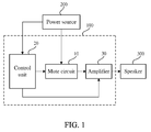
- FIG. 1 is a block diagram of an audio apparatus in accordance with an exemplary embodiment.
- FIG. 2 is a circuit diagram of the audio apparatus of FIG. 1 with an exemplary embodiment.
- an audio apparatus 100 connects a power source 200 with a speaker 300.
- the audio apparatus 100 includes a mute circuit 10, a control unit 20, and an amplifier 30.
- the mute circuit 10 and the control unit 20 receive a supply voltage from the power source 200.
- the control unit 20 is used for providing an audio signal to the amplifier 30.
- the amplifier 30 is used for amplifying the audio signal and providing the amplified audio signal to the speaker 300 for reproducing sound.
- the mute circuit 10 is used for generating a mute signal when initially receiving the supply voltage from the power source 200.
- the amplifier 30 stops driving the speaker 300 to reproduce sound in response to the mute signal, thus noise generated by the speaker 300 when the audio apparatus 100 is powered on is eliminated.
- the power source 200 includes a power supply and a capacitor, when the power supply provides the supply voltage to the mute circuit 10 and the control unit 20, the supply voltage charges up the capacitor. When the power supply stops providing the supply voltage, the capacitor discharges, thus the mute circuit 10 and the control unit 20 are powered, momentarily, by the capacitor.
- the control unit 20 is used for generating a trigger signal when not receiving the supply voltage from the power source 200.
- the mute circuit 10 generates the mute signal to the amplifier 30 according to the trigger signal, and the amplifier 30 stops driving the speaker 300 to reproduce sound in response to the mute signal, thus noise generated by the speaker 300 when the audio apparatus 100 is powered off is eliminated.
- the power source 200 includes a power supply Vcc for providing the supply voltage and a first capacitor C1. One end of the first capacitor C1 is connected to the power supply Vcc, and the other end of the first capacitor C1 is grounded.
- the power supply Vcc couples the mute circuit 10 and the control unit 20.
- the mute circuit 10 includes a first unit 12, a signal generating unit 14, and a second unit 16.
- the first unit 12 is used for generating a first level signal when receiving the supply voltage from the power source 200
- the signal generating unit 14 receives the first level signal and the supply voltage to generate the mute signal.
- the amplifier 30 stops driving the speaker 300 to reproduce sound according to the mute signal.
- the first unit 12 further generates a second level signal when having received the supply voltage from the power source 200 for a predetermined time period, the signal generating unit 14 receives the second level signal and the supply voltage to stop generating the mute signal.
- the amplifier 30 drives the speaker to reproduce sound.
- the first level signal is a low level voltage signal
- the second level signal is a high level voltage signal.
- the second unit 16 receives the trigger signal from the control unit 20 to generate the first level signal
- the signal generating unit 14 receives the first level signal from the second unit 16 and the supply voltage from the power source 200 to generate the mute signal.
- the first unit 12 includes a first resistor R1, a second resistor R2, and a second capacitor C2. One end of the first resistor R1 is connected to the power supply Vcc, and the other end of the first resistor R1 is grounded through the second capacitor C2. One end of the second resistor R2 is connected between the first resistor R1 and the second capacitor C2, and the other end of the second resistor R2 is connected to the signal generating unit 14 and the second unit 16.
- the signal generating unit 14 includes a third resistor R3, a fourth resistor R4, a first transistor Q1, a second transistor Q2, and a third transistor Q3.
- a base of the first transistor Q1 is connected to the second resistor R2 and the second unit 16 through the third resistor R3, an emitter of the first transistor Q1 is connected to the power source 200, a collector of the first transistor Q1 is connected to the collector of the second transistor Q2 and the base of the third transistor Q3.
- the base of the second transistor Q2 is connected to the power source 200 through the fourth resistor R4, the emitter of the second transistor Q2 is connected between the first resistor R1 and the first capacitor C1, the collector of the third transistor Q3 is connected to the amplifier 30, the emitter of the third transistor Q3 is grounded.
- the second unit 16 includes a fifth resistor R5, a sixth resistor R6, a third capacitor C3, and a fourth transistor Q4.
- the base of the fourth transistor Q4 is connected to the control unit 20 through the fifth resistor R5, the collector of the fourth transistor Q4 is connected to the second resistor R2 and the third resistor R3, the emitter of the fourth transistor Q4 is grounded.
- the sixth resistor R6 and the third capacitor C3 are connected between the base of the fourth transistor Q4 and ground in parallel.
- the first transistor Q1 and the second transistor Q2 are PNP type transistor
- the third transistor Q3 and the fourth transistor Q4 are NPN type transistor.
- the principal of the audio apparatus 100 is illustrated as follows:
- the power supply Vcc starts to provide the supply voltage to the first unit 12
- the voltage across the second capacitor C2 is zero volts
- the first transistor Q1 turns on
- the third transistor Q3 also turns on.
- the amplifier 30 receives a low level voltage signal, thus amplifier 30 stops driving the speaker 300 to reproduce sound.
- the supply voltage from the power supply Vcc charges up the second capacitor C2 through the first resistor R1 and the first capacitor C1, after a predetermined time period, the voltage across the second capacitor C2 is equal to the supply voltage.
- the first transistor Q1 is cut off, the third transistor Q3 is also cut off.
- the amplifier 30 cannot receive the low level voltage signal and drives the speaker 300 to reproduce sound.
- the control unit 20 receives the discharge voltage from the first capacitor C1 and generates a high level voltage signal.
- the base of the fourth transistor Q4 receives the high level voltage signal through the fifth resistor R5, and the fourth transistor Q4 is turned on.
- the base of the first transistor Q1 is pulled low, the emitter of the first transistor Q1 is pulled high by the discharge voltage of the second capacitor C2, and the first transistor Q1 is turned on.
- the base of the third capacitor Q3 is pulled high by the discharge voltage of the second capacitor C2, and the third capacitor Q3 is turned on.
- the amplifier 30 receives a low level voltage signal, thus amplifier 30 stops driving the speaker 300 to reproduce sound. Therefore, noise generated by the speaker 300 is eliminated when the audio apparatus 100 is powered on or off.
Landscapes
- Engineering & Computer Science (AREA)
- Power Engineering (AREA)
- Amplifiers (AREA)
- Circuit For Audible Band Transducer (AREA)
Applications Claiming Priority (1)
| Application Number | Priority Date | Filing Date | Title |
|---|---|---|---|
| CN2009103127395A CN102118669A (zh) | 2009-12-30 | 2009-12-30 | 音频装置 |
Publications (2)
| Publication Number | Publication Date |
|---|---|
| EP2343801A2 true EP2343801A2 (de) | 2011-07-13 |
| EP2343801A3 EP2343801A3 (de) | 2013-07-03 |
Family
ID=43654818
Family Applications (1)
| Application Number | Title | Priority Date | Filing Date |
|---|---|---|---|
| EP10195276.0A Withdrawn EP2343801A3 (de) | 2009-12-30 | 2010-12-15 | Audiovorrichtung |
Country Status (4)
| Country | Link |
|---|---|
| US (1) | US20110158429A1 (de) |
| EP (1) | EP2343801A3 (de) |
| JP (1) | JP2011139444A (de) |
| CN (1) | CN102118669A (de) |
Cited By (1)
| Publication number | Priority date | Publication date | Assignee | Title |
|---|---|---|---|---|
| EP3512095A4 (de) * | 2016-09-12 | 2020-02-26 | BOE Technology Group Co., Ltd. | Steuerungsschaltung, steuerungsverfahren und elektronische vorrichtung |
Families Citing this family (5)
| Publication number | Priority date | Publication date | Assignee | Title |
|---|---|---|---|---|
| CN104185119A (zh) * | 2013-05-23 | 2014-12-03 | 鸿富锦精密工业(深圳)有限公司 | 音频装置 |
| CN103634725A (zh) * | 2013-12-10 | 2014-03-12 | 惠州市德赛西威汽车电子有限公司 | 一种静音控制方法及电路 |
| CN104640028B (zh) * | 2015-03-05 | 2018-06-19 | 浪潮集团有限公司 | 一种基于全国产飞腾处理器平台音频mute线路 |
| CN106686492B (zh) * | 2017-01-22 | 2019-06-25 | 深圳市华星光电技术有限公司 | 一种音频输出电路及音频设备 |
| CN107889030A (zh) * | 2017-11-20 | 2018-04-06 | 深圳市沃特沃德股份有限公司 | 控制功率放大器的方法和装置 |
Family Cites Families (13)
| Publication number | Priority date | Publication date | Assignee | Title |
|---|---|---|---|---|
| US3350650A (en) * | 1964-06-17 | 1967-10-31 | Collins Radio Co | Noise and audio controlled squelch circuit |
| JPS56150114U (de) * | 1980-04-10 | 1981-11-11 | ||
| JPS5762605A (en) * | 1980-10-02 | 1982-04-15 | Matsushita Electric Ind Co Ltd | Suppressing device for electric power on-and-off sound of amplifier |
| US5606624A (en) * | 1993-05-13 | 1997-02-25 | Bose Corporation | Audio apparatus demonstrating |
| JPH08148941A (ja) * | 1994-11-18 | 1996-06-07 | Toa Corp | ミューティング装置 |
| JP2000315920A (ja) * | 1999-05-06 | 2000-11-14 | Matsushita Electric Ind Co Ltd | 音声ミュート回路 |
| JP2002354571A (ja) * | 2001-05-08 | 2002-12-06 | Lg Electronics Inc | 音声ミューティング回路 |
| TWI327871B (en) * | 2006-01-05 | 2010-07-21 | Chunghwa Picture Tubes Ltd | Circuit for suppressing audio noise |
| US8218793B2 (en) * | 2006-12-11 | 2012-07-10 | Mediatek Inc. | Apparatus and muting circuit |
| CN100566139C (zh) * | 2006-12-11 | 2009-12-02 | 联发科技股份有限公司 | 音频装置与消音装置 |
| JP2009152690A (ja) * | 2007-12-18 | 2009-07-09 | Kenwood Corp | ミュート回路 |
| TWI351023B (en) * | 2008-02-15 | 2011-10-21 | Hon Hai Prec Ind Co Ltd | Pop noise suppression apparatus and audio output system utilizing the same |
| CN101247115B (zh) * | 2008-03-14 | 2011-05-25 | 北京创毅视讯科技有限公司 | 一种静音电路 |
-
2009
- 2009-12-30 CN CN2009103127395A patent/CN102118669A/zh active Pending
-
2010
- 2010-11-24 US US12/953,493 patent/US20110158429A1/en not_active Abandoned
- 2010-12-07 JP JP2010272381A patent/JP2011139444A/ja active Pending
- 2010-12-15 EP EP10195276.0A patent/EP2343801A3/de not_active Withdrawn
Non-Patent Citations (1)
| Title |
|---|
| None |
Cited By (1)
| Publication number | Priority date | Publication date | Assignee | Title |
|---|---|---|---|---|
| EP3512095A4 (de) * | 2016-09-12 | 2020-02-26 | BOE Technology Group Co., Ltd. | Steuerungsschaltung, steuerungsverfahren und elektronische vorrichtung |
Also Published As
| Publication number | Publication date |
|---|---|
| US20110158429A1 (en) | 2011-06-30 |
| JP2011139444A (ja) | 2011-07-14 |
| EP2343801A3 (de) | 2013-07-03 |
| CN102118669A (zh) | 2011-07-06 |
Similar Documents
| Publication | Publication Date | Title |
|---|---|---|
| CN103167379B (zh) | 音频播放装置 | |
| EP2343801A2 (de) | Audiovorrichtung | |
| TW201021585A (en) | A mute circuit, an electronic device and a method for eliminating audible noise | |
| US20090028349A1 (en) | Method and apparatus for detecting malfunctioning speaker | |
| US20080137882A1 (en) | Apparatus and muting circuit | |
| US20130156226A1 (en) | Volume adjustment circuit with automatic gain control and electronic device using same | |
| US8335322B2 (en) | Mute control circuit and electronic device using same | |
| CN103379400A (zh) | 耳机侦测电路及具有该耳机侦测电路的电子装置 | |
| TW201513564A (zh) | 具音頻控制電路的電子裝置 | |
| CN102025325B (zh) | 音频放大器和使用它的电子设备 | |
| JP5514036B2 (ja) | オーディオ用増幅器およびそれを用いた電子機器 | |
| US8103021B2 (en) | Audio reproducing apparatus | |
| US20090274319A1 (en) | Audio amplifier | |
| CN101111094B (zh) | 异音防止模块与其扩音装置 | |
| CN101516050B (zh) | 爆音消除装置及使用所述装置的声音输出系统 | |
| CN110677778B (zh) | 一种音频静音控制电路及电子设备 | |
| US7663433B2 (en) | Audio amplifier | |
| CN104185119A (zh) | 音频装置 | |
| CN108391203A (zh) | 音频播放控制方法及装置、音频播放设备及系统 | |
| CN100583632C (zh) | 声音噪声抑制电路 | |
| CN211792015U (zh) | 音频播放电路和对讲设备 | |
| CN101958646B (zh) | 电源补偿装置及方法 | |
| TWI429300B (zh) | 電子設備 | |
| US20070093221A1 (en) | Audio muting circuit and audio muting method | |
| US20120207330A1 (en) | Audio signal amplifying circuit |
Legal Events
| Date | Code | Title | Description |
|---|---|---|---|
| PUAI | Public reference made under article 153(3) epc to a published international application that has entered the european phase |
Free format text: ORIGINAL CODE: 0009012 |
|
| AK | Designated contracting states |
Kind code of ref document: A2 Designated state(s): AL AT BE BG CH CY CZ DE DK EE ES FI FR GB GR HR HU IE IS IT LI LT LU LV MC MK MT NL NO PL PT RO RS SE SI SK SM TR |
|
| AX | Request for extension of the european patent |
Extension state: BA ME |
|
| PUAL | Search report despatched |
Free format text: ORIGINAL CODE: 0009013 |
|
| AK | Designated contracting states |
Kind code of ref document: A3 Designated state(s): AL AT BE BG CH CY CZ DE DK EE ES FI FR GB GR HR HU IE IS IT LI LT LU LV MC MK MT NL NO PL PT RO RS SE SI SK SM TR |
|
| AX | Request for extension of the european patent |
Extension state: BA ME |
|
| RIC1 | Information provided on ipc code assigned before grant |
Ipc: H03F 1/30 20060101ALI20130528BHEP Ipc: H03G 3/34 20060101AFI20130528BHEP |
|
| STAA | Information on the status of an ep patent application or granted ep patent |
Free format text: STATUS: THE APPLICATION IS DEEMED TO BE WITHDRAWN |
|
| 18D | Application deemed to be withdrawn |
Effective date: 20140104 |