EP2343525A2 - Verfahren und Vorrichtung zur Abschätzung der beim Berühren einer Oberfläche empfundenen Temperatur - Google Patents
Verfahren und Vorrichtung zur Abschätzung der beim Berühren einer Oberfläche empfundenen Temperatur Download PDFInfo
- Publication number
- EP2343525A2 EP2343525A2 EP20100193903 EP10193903A EP2343525A2 EP 2343525 A2 EP2343525 A2 EP 2343525A2 EP 20100193903 EP20100193903 EP 20100193903 EP 10193903 A EP10193903 A EP 10193903A EP 2343525 A2 EP2343525 A2 EP 2343525A2
- Authority
- EP
- European Patent Office
- Prior art keywords
- temperature
- heating
- estimating
- touching
- heat
- Prior art date
- Legal status (The legal status is an assumption and is not a legal conclusion. Google has not performed a legal analysis and makes no representation as to the accuracy of the status listed.)
- Granted
Links
Images

Classifications
-
- G—PHYSICS
- G01—MEASURING; TESTING
- G01K—MEASURING TEMPERATURE; MEASURING QUANTITY OF HEAT; THERMALLY-SENSITIVE ELEMENTS NOT OTHERWISE PROVIDED FOR
- G01K7/00—Measuring temperature based on the use of electric or magnetic elements directly sensitive to heat ; Power supply therefor, e.g. using thermoelectric elements
- G01K7/42—Circuits effecting compensation of thermal inertia; Circuits for predicting the stationary value of a temperature
Definitions
- the invention relates to a method and a device for estimating the temperature sensed when touching a surface.
- the invention is particularly advantageous for use in the automotive industry, the invention is not limited thereto. Rather, the invention is applicable in all technological fields in which the perception of quality (in particular feel and feelability) of products is to be optimized, e.g. also in the electronics or furniture industry.
- the measurement or estimation of the contact temperature of a surface can e.g. be necessary to be able to quantitatively assess the visible and palpable authenticity or authenticity of materials.
- the so-called heat penetration coefficient also: heat penetration number
- this heat penetration coefficient is conventionally determined only in large-scale machines on test materials.
- the size of the measuring device used for this purpose should be such that it is e.g. can be handled by a measuring robot.
- thermoelectric voltage For example, a method for determining thermal conductivity based on thermovoltage measurements by means of an actuator-sensor system on a material in which a temperature gradient has been generated is known.
- the required temperature difference by an in generates a first mode operated as a Peltier element actuator.
- the supply and removal of the current-proportional Peltier heat is briefly and periodically interrupted, the actuator during these interruptions by electronic switching in a second mode operates as a sensor that detects the current temperature difference-proportional thermoelectric voltage.
- a method for estimating the temperature sensed when contacting a surface comprises the steps of: non-contact heating of the surface, non-contact measurement of the temporal temperature change of the surface, and estimating the temperature sensed upon contacting the surface based on this temporal temperature change.
- the fact that the method according to the invention works non-contact and non-destructive ensures that no changes are made to the surface to be examined and thus no residues remain, so that the method is also suitable for use in comparative studies or benchmark tests.
- the method according to the invention makes possible the non-destructive and mobile estimation of the temperature perceived by humans for a wide variety of surfaces or materials such as metal, wood, plastic, foam, etc.
- non-contact technologies for heating or heating the surface can be used. Without the invention being limited thereto, these technologies may be used e.g. the use of halogen light, infrared light, light from a laser light source or the use of heat conduction (via the supply of heated air, for example by means of a blower) include.
- modifications can be used to standardize the surface. These modifications may include the use of thermal grease, of (paper) stickers or tapes having a specific permeability behavior, the use of a suitable liquid (eg, two volumes of matte black paint and one part by volume of isopropanol), or the use of soot particles stored in Teflon filters, and of These can be transferred to the respective samples include and combined with each other in a suitably compact manner, so that the modification or standardization can be applied both in the laboratory and mobile (eg in a measuring robot).
- a suitable liquid eg, two volumes of matte black paint and one part by volume of isopropanol
- soot particles stored in Teflon filters can be transferred to the respective samples include and combined with each other in a suitably compact manner, so that the modification or standardization can be applied both in the laboratory and mobile (eg in a measuring robot).
- the step of heating the surface comprises clocked heating of the surface. This makes it possible to distinguish different surfaces or materials to be examined with a higher resolution in comparison to a constant, uniform heating, since the respectively obtained, the time dependence of the temperature change describing functions or waveforms not only in the slope (the respective Regression line), but also in the individual caused by the clocked heating decay curves from each other.
- the step of estimating the temperature sensed when touching the surface is based on a calibration in which the o. Parameter for a plurality of reference surfaces is determined.
- this calibration comprises the assignment of the parameters (v1) determined for the plurality of reference surfaces to a respective value of the heat penetration number (defined below) for the relevant reference surface.
- the invention relates to a device for estimating the temperature sensed when touching a surface, comprising a heat source for non-contact heating of the surface, a thermometer for non-contact measuring the temperature of the surface and an evaluation unit based on a heating caused temporal change of the temperature of the surface determines a characteristic of the temperature sensed when touching the surface temperature.
- the device is designed for cycled heating of the surface by means of the heat source.
- the device can in particular be a rotatable, provided with at least one opening Shielding, wherein the surface through the opening with heat energy can be acted upon.
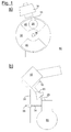
- Fig. 1a and 1b show only schematically the structure of a measuring arrangement according to the invention in a schematic front view ( Fig. 1a ) or side view ( Fig. 1 b) ,
- the arrangement according to Fig. 1 has a designed in the embodiment as a halogen lamp heat source 20 and held by a carrier 15 (infrared) thermometer 10.
- a halogen lamp heat source 20 and held by a carrier 15 (infrared) thermometer 10.
- the heating described below is performed by using a halogen lamp as a heat source, the invention is not limited thereto.
- a non-contact Heating by means of an infrared lamp, an incandescent lamp, a laser light source or by means of a fan or a controllable H combin Kunststoffföns done.
- the heat source 20 in the embodiment of Fig. 1 forming halogen lamp is in turn held by a carrier 25, which in the embodiment of the housing of an electric motor 50 is fixed (eg screwed).
- a shaft 35 of the electric motor 50 is fixed via a screw-nut connection 36 to a rotatable disk or shield 30, which has openings 40 for the passage of light or heat and otherwise (at least substantially) is heat or opaque.
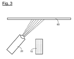
- thermometer 10 is according to Fig. 2 mounted so that it can measure over the edge of the rotatable disk 30 the temperature on a sample surface of a sample 60, typically a distance of some (eg 5-20) cm from the surface to be characterized.
- a suitable homogenization or surface modification is carried out in advance on the sample 60 to be examined, after which all samples have matching color properties and surface structures.
- a commercially available thermal paste, a (paper) sticker or tape with suitable permeability (preferably a low reflectance), a suitable liquid (eg with two volumes of matte black color and one part by volume of isopropanol) or (eg in Teflon filters stored) soot particles are applied.
- Fig. 1a-b and Fig. 2 illustrated arrangement performed a clocked heating of the surface in question, in each case for the calibration of the arrangement in each case first for a series of reference samples (so-called. "Sensotact-samples").
- the individual reference samples consist of mutually different materials (such as Styrofoam, wood, Teflon or aluminum).
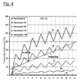
- the heating by means of periodic clocking is in this case due to in the arrangement of Fig. 1a-b and Fig. 2 achieves rotating apertures 40 in the disc or shield 30 and results in measuring the temperature change as a function of time according to Fig. 4 characteristic sawtooth curves "A" to "E" (for the Sensotact samples used for calibration with the sample designations 0, 20, 50, 70 and 100).
- the timing can be selected merely by way of example so that measured values are recorded at a frequency of 1 Hz.
- a comparison coefficient vl 1 m ⁇ a where m is the slope of the regression line and a is the average amplitude of the decay curves.
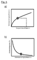
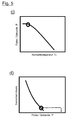
- the plot of the comparison coefficients v1 determined for the respective reference samples or heat input numbers b gives the in Fig. 5a schematically illustrated correlation.
- a corresponding value for the heat penetration number b and thus a contact temperature T c of the material under investigation can thus be determined in a subsequent measurement for each comparison value v 1 Fig. 5b be assigned.
- the contact temperature T c in turn correlates directly with the human temperature perception, so the temperature sensation in the contact of different surfaces can be at least approximately quantified.
Landscapes
- Physics & Mathematics (AREA)
- General Physics & Mathematics (AREA)
- Investigating Or Analyzing Materials Using Thermal Means (AREA)
Abstract
Description
- Die Erfindung betrifft ein Verfahren sowie eine Vorrichtung zur Abschätzung der beim Berühren einer Oberfläche empfundenen Temperatur. Wenngleich die Erfindung insbesondere vorteilhaft in der Kraftfahrzeugindustrie einsetzbar ist, ist die Erfindung hierauf nicht beschränkt. Vielmehr ist die Erfindung in sämtlichen technologischen Bereichen anwendbar, in welchen die Qualitätswahrnehmung (insbesondere Haptik und Fühlbarkeit) von Produkten optimiert werden soll, also z.B. auch in der Elektronik- oder Möbelindustrie.
- Die Messung bzw. Abschätzung der Kontakttemperatur einer Oberfläche kann z.B. erforderlich sein, um die sichtbare und fühlbare Authentizität bzw. Echtheit von Materialien quantitativ einschätzen zu können. Hierbei kann als charakteristischer Parameter der sogenannte Wärmeeindringkoeffizient (auch: Wärmeeindringzahl) bestimmt werden. Dabei tritt das Problem auf, dass dieser Wärmeeindringkoeffizient herkömmlicherweise nur in großmaßstäbigen Maschinen an Testmaterialien bestimmt wird.
- Insbesondere in Kraftfahrzeugen besteht aber ein Bedarf, das Temperaturempfinden bei der Berührung unterschiedlicher, insbesondere im Fahrzeuginnenraum vorkommender Materialien bzw. den Wärmeeindringkoeffizienten der im Fahrzeuginnenraum vorhandenen Materialien zerstörungsfrei, kontaktlos sowie unabhängig von der Oberflächengestaltung abzuschätzen. Zugleich sollte die Größe der hierzu eingesetzten Messvorrichtung dergestalt sein, dass diese z.B. von einem Messroboter handhabbar ist.
- Aus
DE 39 01 377 A1 ist ein Verfahren zur Wärmeleitfähigkeitsbestimmung auf der Grundlage von Thermospannungsmessungen mittels eines Aktor-SensorSystems an einem Material bekannt, in dem ein Temperaturgefälle erzeugt wurde. Bei diesem Verfahren wird die erforderliche Temperaturdifferenz durch einen in einer ersten Betriebsart als Peltierelement betriebenen Aktor erzeugt. Die Zu- bzw. Abführung der stromproportionalen Peltierwärme wird kurzzeitig und periodisch unterbrochen, wobei der Aktor während dieser Unterbrechungen durch elektronische Umschaltung in einer zweiten Betriebsart als Sensor arbeitet, der die momentane temperaturdifferenzproportionale Thermospannung erfasst. - Eine Aufgabe der vorliegenden Erfindung besteht darin, ein Verfahren sowie eine Vorrichtung zur Abschätzung der beim Berühren einer Oberfläche empfundenen Temperatur bereitzustellen, welches bzw. welche eine zuverlässige Charakterisierung unabhängig von der konkreten Oberflächengestaltung wie z.B. Oberflächenfarbe oder Transmissionsverhalten ermöglicht und zugleich zerstörungsfrei sowie mobil einsetzbar ist.
- Diese Aufgabe wird durch ein Verfahren gemäß den Merkmalen des unabhängigen Patentanspruchs 1 sowie eine Vorrichtung gemäß den Merkmalen des unabhängigen Patentanspruchs 7 gelöst.
- Ein Verfahren zur Abschätzung der beim Berühren einer Oberfläche empfundenen Temperatur weist folgende Schritte auf: Berührungsloses Erwärmen der Oberfläche, Berührungsloses Messen der zeitlichen Temperaturänderung der Oberfläche, und Abschätzen der beim Berühren der Oberfläche empfundenen Temperatur auf Basis dieser zeitlichen Temperaturänderung.
- Dadurch, dass das erfindungsgemäße Verfahren berührungslos und zerstörungsfrei arbeitet, wird sichergestellt, dass keine Veränderungen an der zu untersuchenden Oberfläche vorgenommen werden und somit auch keine Rückstände bestehen bleiben, so dass das Verfahren auch für den Einsatz in Vergleichsstudien bzw. Benchmark-Tests geeignet ist. Das erfindungsgemäße Verfahren ermöglicht hierbei die zerstörungsfreie sowie mobil einsetzbare Abschätzung der vom Menschen empfundenen Temperatur für eine breite Vielfalt von Oberflächen bzw. Materialien wie z.B. Metall, Holz, Kunststoff, Schaumstoff, etc.
- Bei dem erfindungsgemäßen Verfahren können unterschiedliche, berührungslose Technologien zum Erwärmen bzw. Aufheizen der Oberfläche eingesetzt werden. Ohne dass die Erfindung hierauf beschränkt wäre, können diese Technologien z.B. die Verwendung von Halogenlicht, Infrarotlicht, Licht einer Laserlichtquelle oder die Ausnutzung von Wärmeleitung (über die Zufuhr von erwärmter Luft etwa mittels eines Gebläses) beinhalten.
- Um sicherzustellen, dass die mittels des erfindungsgemäßen Verfahrens erzielten Ergebnisse objektiv vergleichbar und unabhängig von der konkreten Oberflächengestaltung sind, insbesondere unabhängig von der jeweiligen Farbe oder dem Transmissionsverhalten der Oberfläche, können diverse Modifikationen zur Vereinheitlichung der Oberfläche eingesetzt werden. Diese Modifikationen können den Einsatz von Wärmeleitpaste, von (Papier-)Aufklebern oder Tapes mit speziellem Durchlässigkeitsverhalten, die Verwendung einer geeigneten Flüssigkeit (z.B. mit zwei Volumenteilen matter schwarzer Farbe und einem Volumenteil Isopropanol) oder den Einsatz von Russpartikeln, welche in Teflonfiltern gespeichert und von diesen auf die jeweiligen Proben übertragen werden können, umfassen und auch in geeigneter kompakter Weise miteinander kombiniert werden, so dass die Modifikation bzw. Vereinheitlichung sowohl im Labor als auch mobil (z.B. in einem Messroboter) angewandt werden kann.
- Gemäß einer Ausführungsform umfasst der Schritt des Erwärmens der Oberfläche ein getaktetes Erwärmen der Oberfläche. Hierdurch wird es möglich, unterschiedliche zu untersuchende Oberflächen bzw. Materialien mit einer im Vergleich zu einer konstanten, gleichmäßigen Erwärmung höheren Auflösung zu unterscheiden, da die jeweils erhaltenen, die Zeitabhängigkeit der Temperaturänderung beschreibenden Funktionen bzw. Messkurven sich nicht nur in der Steigung (der jeweiligen Regressionsgerade), sondern auch in den einzelnen durch die getaktete Erwärmung erzeugten Abklingkurven voneinander unterscheiden.
- Gemäß einer Ausführungsform umfasst der Schritt des Abschätzens der beim Berühren der Oberfläche empfundenen Temperatur die Ermittlung eines Parameters vl, der gegeben ist durch

wobei m die Steigung einer für die die Zeitabhängigkeit der Temperaturänderung beschreibenden Funktion ermittelten Regressionsgerade und a die mittlere Amplitude der durch die getaktete Erwärmung erzeugten Abklingkurven in dieser Funktion bezeichnen. - Gemäß einer Ausführungsform erfolgt der Schritt des Abschätzens der beim Berühren der Oberfläche empfundenen Temperatur auf Basis einer Kalibrierung, in welcher der o.g. Parameter für eine Mehrzahl von Referenzoberflächen ermittelt wird.
- Gemäß einer Ausführungsform umfasst diese Kalibrierung die Zuordnung der für die Mehrzahl von Referenzoberflächen ermittelten Parameter (vl) zu einem jeweiligen, für die betreffende Referenzoberfläche bekannten Wert der (im Weiteren definierten) Wärmeeindringzahl.
- Gemäß einem weiteren Aspekt betrifft die Erfindung eine Vorrichtung zur Abschätzung der beim Berühren einer Oberfläche empfundenen Temperatur, welche eine Wärmequelle zum berührungsfreien Erwärmen der Oberfläche, ein Thermometer zur berührungsfreien Messen der Temperatur der Oberfläche und eine Auswerteeinheit aufweist, welche auf Basis einer durch das Erwärmen hervorgerufenen zeitlichen Änderung der Temperatur der Oberfläche einen für die beim Berühren der Oberfläche empfundene Temperatur charakteristischen Parameter ermittelt.
- Gemäß einer Ausführungsform ist die Vorrichtung zum getakteten Erwärmen der Oberfläche mittels der Wärmequelle ausgelegt. Hierzu kann die Vorrichtung insbesondere eine rotierbare, mit wenigstens einer Öffnung versehene Abschirmung aufweisen, wobei die Oberfläche durch die Öffnung hindurch mit Wärmeenergie beaufschlagbar ist.
- Weitere Ausgestaltungen der Erfindung sind der Beschreibung sowie den Unteransprüchen zu entnehmen.
- Die Erfindung wird nachstehend anhand bevorzugter Ausführungsformen unter Bezugnahme auf die beigefügten Abbildungen näher erläutert.
- Es zeigen:
- Figur 1a-b
- den Aufbau einer Messanordnung in schematischer Vorderansicht (
Figur 1 a) bzw. Seitenansicht (Figur 1 b) gemäß einer Ausführungsform der Erfindung; - Figur 2-3
- schematische Darstellungen zur Erläuterung der Arbeitsweise der Messanordnung von
Figur 1 ; und - Figur 4-5
- Diagramme zur Erläuterung des erfindungsgemäßen Verfahrens sowie der Kalibrierung der Messanordnung von
Figur 1 . - Die
Fig. 1a und 1b zeigen lediglich schematisch den Aufbau einer erfindungsgemäßen Messanordnung in schematischer Vorderansicht (Fig. 1a ) bzw. Seitenansicht (Fig. 1 b) . - Die Anordnung gemäß
Fig. 1 weist eine im Ausführungsbeispiel als Halogenlampe ausgestaltete Wärmequelle 20 sowie ein von einem Träger 15 gehaltenes (Infrarot-)Thermometer 10 auf. Wenngleich die im Weiteren beschriebene Erwärmung unter Verwendung einer Halogenlampe als Wärmequelle vorgenommen wird, ist die Erfindung nicht hierauf beschränkt. So kann gemäß weiterer, nicht dargestellter Ausführungsformen auch eine berührungslose Erwärmung mittels einer Infrarotlampe, einer Glühlampe, einer Laserlichtquelle oder mittels eines Gebläses bzw. eines regelbaren Heißluftföns erfolgen. - Die die Wärmequelle 20 im Ausführungsbeispiel von
Fig. 1 bildende Halogenlampe wird ihrerseits über einen Träger 25 gehalten, welcher im Ausführungsbeispiel an dem Gehäuse eines Elektromotors 50 fixiert (z.B. verschraubt) ist. Eine Welle 35 des Elektromotors 50 ist über eine SchraubenMutter-Verbindung 36 an eine drehbare Scheibe bzw. Abschirmung 30 fixiert, welche Öffnungen 40 für den Durchlass von Licht bzw. Wärme aufweist und im Übrigen (zumindest im Wesentlichen) wärme- bzw. lichtundurchlässig ist. - Das Thermometer 10 ist gemäß
Fig. 2 so angebracht, dass es über den Rand der drehbaren Scheibe bzw. Abschirmung 30 hinweg die Temperatur auf einer Probenoberfläche einer Probe 60 messen kann, wobei typischerweise ein Abstand von einigen (z.B. 5-20) cm von der zu charakterisierenden Oberfläche besteht. - Zur Sicherstellung einer objektiven bzw. von Farbe und Transmissionseigenschaften der jeweiligen Oberflächen unabhängigen Messung wird vorab an der zu untersuchenden Probe 60 eine geeignete Homogenisierung bzw. Oberflächenmodifikation durchgeführt, nach der sämtliche Proben übereinstimmende Farbeigenschaften sowie Oberflächenstrukturen besitzen. Hierzu können auf die jeweiligen Oberflächen beispielsweise eine handelsübliche Wärmeleitpaste, ein (Papier-)Aufkleber oder Tape mit geeignetem Durchlässigkeitsverhalten (vorzugsweise einem geringen Reflexionsgrad), eine geeignete Flüssigkeit (z.B. mit zwei Volumenteilen matter schwarzer Farbe und einem Volumenteil Isopropanol) oder (z.B. in Teflonfiltern gespeicherte) Russpartikel aufgebracht werden.
- Im Weiteren wird unter Bezugnahme auf
Fig. 4 undFig. 5a-d die erfindungsgemäße Bestimmung der Kontakttemperatur eines zu untersuchenden Materials bzw. die Quantifizierung des Temperaturgefühls bei der Berührung der betreffenden Oberfläche erläutert. - Bei dem erfindungsgemäßen Verfahren wird unter Verwendung der in den
Fig. 1a-b undFig. 2 dargestellten Anordnung eine getaktete Erwärmung der betreffenden Oberfläche durchgeführt, und zwar zur Kalibrierung der Anordnung jeweils zunächst für eine Reihe von Referenzproben (sog. "Sensotact-Proben"). Die einzelnen Referenzproben bestehen aus voneinander verschiedenen Materialien (wie z.B. Styropor, Holz, Teflon oder Aluminium). - Die Erwärmung mittels periodischer Taktung wird hierbei aufgrund der in der Anordnung von
Fig. 1a-b undFig. 2 rotierenden Öffnungen 40 in der Scheibe bzw. Abschirmung 30 erzielt und ergibt bei Messung der Temperaturänderung in Abhängigkeit von der Zeit gemäßFig. 4 charakteristische Sägezahnkurven "A" bis "E" (für die zur Kalibrierung verwendeten Sensotact-Proben mit den Proben-Bezeichnungen 0, 20, 50, 70 und 100). Die Taktung kann dabei lediglich beispielhaft so gewählt werden, dass mit einer Frequenz von 1 Hz Messwerte aufgezeichnet werden. - Aus diesen Sägezahnkurven werden gemäß
Fig. 4 zum einen die Steigung der Regressionsgerade (durch die Messkurve Temperaturänderung vs. Zeit) und zum anderen die Amplituden der Abklingkurven der einzelnen, durch die getaktete Erwärmung erzeugten "Schwingungen" berechnet. - Aus den durchschnittlichen Amplitudenwerten und dem Wert der Steigung wird sodann ein Vergleichskoeffizient vl wie folgt bestimmt:

wobei m die Steigung der Regressionsgerade und a die durchschnittliche Amplitude der Abklingkurven bezeichnen. - Die zur Kalibrierung verwendeten Referenz- bzw. Sensotact-Proben weisen ferner unterschiedliche, jeweils bekannte Werte für die Wärmeeindringzahl b auf, welche wie folgt definiert ist:

mit
und - b:
- Wärmeeindringzahl
- λ
- Wärmeleitfähigkeit
- c:
- Wärmekapazität
- γ :
- Dichte
- ϑ0 :
- Temperatur der Oberfläche
- Die Auftragung der zu den jeweiligen Referenzproben bzw. Wärmeeindringzahlen b ermittelten Vergleichskoeffizienten vl ergibt die in
Fig. 5a schematisch dargestellte Korrelation. Über diese Korrelation kann somit bei einer nachfolgenden Messung jedem Vergleichswert vl ein entsprechender Wert für die Wärmeeindringzahl b und somit eine Kontakttemperatur Tc des untersuchten Materials gemäßFig. 5b zugeordnet werden. - Da die Kontakttemperatur Tc wiederum direkt mit der menschlichen Temperaturwahrnehmung korreliert, kann also auch das Temperaturgefühl bei der Berührung unterschiedlicher Oberflächen zumindest näherungsweise quantifiziert werden. Dies ist schematisch in den
Fig. 5c und 5d dargestellt, wobei inFig. 5c der Kontakttemperatur Tc die Pulsrate bzw. Anzahl von Pulsen pro Sekunde (der Thermorezeptoren) und inFig. 5d dieser Pulsrate ein entsprechender Skalenwert, z.B. auf einer Skala von 0 (= kalt) bis 100 (= warm) zur Charakterisierung der beim Berühren einer Oberfläche empfundenen Temperatur zugeordnet wird.
Claims (9)
- Verfahren zur Abschätzung der beim Berühren einer Oberfläche empfundenen Temperatur,
dadurch gekennzeichnet, dass
das Verfahren folgende Schritte aufweist:a) Berührungsloses Erwärmen der Oberfläche;b) Berührungsloses Messen der zeitlichen Temperaturänderung der Oberfläche; undc) Abschätzen der beim Berühren der Oberfläche empfundenen Temperatur auf Basis dieser zeitlichen Temperaturänderung. - Verfahren nach Anspruch 1,
dadurch gekennzeichnet, dass
die Oberfläche vor dem Schritt a) des Erwärmens zur Vereinheitlichung von Farbe und/oder Transmissionsverhalten der Oberfläche modifiziert wird. - Verfahren nach Anspruch 1 oder 2,
dadurch gekennzeichnet, dass
dass der Schritt a) des Erwärmens ein getaktetes Erwärmen der Oberfläche umfasst. - Verfahren nach Anspruch 3,
dadurch gekennzeichnet, dass
der Schritt c) des Abschätzens der beim Berühren der Oberfläche empfundenen Temperatur die Ermittlung eines Parameters (vl) umfasst, der gegeben ist durch
wobei m die Steigung einer für die die Zeitabhängigkeit der Temperaturänderung beschreibenden Funktion ermittelten Regressionsgerade und a die mittlere Amplitude der durch die getaktete Erwärmung erzeugten Abklingkurven in dieser Funktion bezeichnen. - Verfahren nach Anspruch 4,
dadurch gekennzeichnet, dass
der Schritt c) des Abschätzens der beim Berühren der Oberfläche empfundenen Temperatur auf Basis einer Kalibrierung erfolgt, in welcher der Parameter (vl) für eine Mehrzahl von Referenzoberflächen ermittelt wird. - Verfahren nach Anspruch 5,
dadurch gekennzeichnet, dass
die Kalibrierung die Zuordnung der für die Mehrzahl von Referenzoberflächen ermittelten Parameter (vl) zu einem jeweiligen, für diese Referenzoberfläche bekannten Wert der Wärmeeindringzahl (b) umfasst, wobei die Wärmeeindringzahl definiert ist als
mit
undb: Wärmeeindringzahlλ: Wärmeleitfähigkeitc: Wärmekapazitätγ : Dichteϑ0: Temperatur der Oberfläche - Vorrichtung zur Abschätzung der beim Berühren einer Oberfläche empfundenen Temperatur,
dadurch gekennzeichnet, dass
die Vorrichtung aufweist:eine Wärmequelle (20) zum berührungslosen Erwärmen der Oberfläche;ein Thermometer (10) zur berührungslosen Messen der Temperatur der Oberfläche; undeine Auswerteeinheit, welche auf Basis einer durch das Erwärmen hervorgerufenen zeitlichen Änderung der Temperatur der Oberfläche einen für die beim Berühren der Oberfläche empfundene Temperatur charakteristischen Parameter (vl) ermittelt. - Vorrichtung nach Anspruch 7,
dadurch gekennzeichnet, dass
die Vorrichtung zum getakteten Erwärmen der Oberfläche mittels der Wärmequelle (20) ausgelegt ist. - Vorrichtung nach Anspruch 8,
dadurch gekennzeichnet, dass
die Vorrichtung zum getakteten Erwärmen der Oberfläche eine rotierbare, mit wenigstens einer Öffnung (40) versehene Abschirmung (30) aufweist, wobei die Oberfläche durch die Öffnung (40) hindurch mit Wärmeenergie beaufschlagbar ist.
Applications Claiming Priority (1)
| Application Number | Priority Date | Filing Date | Title |
|---|---|---|---|
| DE102010000701A DE102010000701A1 (de) | 2010-01-06 | 2010-01-06 | Verfahren und Vorrichtung zur Abschätzung der beim Berühren einer Oberfläche empfundenen Temperatur |
Publications (3)
| Publication Number | Publication Date |
|---|---|
| EP2343525A2 true EP2343525A2 (de) | 2011-07-13 |
| EP2343525A3 EP2343525A3 (de) | 2015-05-27 |
| EP2343525B1 EP2343525B1 (de) | 2016-09-21 |
Family
ID=43827544
Family Applications (1)
| Application Number | Title | Priority Date | Filing Date |
|---|---|---|---|
| EP10193903.1A Active EP2343525B1 (de) | 2010-01-06 | 2010-12-07 | Verfahren und Vorrichtung zur Abschätzung der beim Berühren einer Oberfläche empfundenen Temperatur |
Country Status (4)
| Country | Link |
|---|---|
| US (1) | US8457918B2 (de) |
| EP (1) | EP2343525B1 (de) |
| CN (1) | CN102116686B (de) |
| DE (1) | DE102010000701A1 (de) |
Families Citing this family (3)
| Publication number | Priority date | Publication date | Assignee | Title |
|---|---|---|---|---|
| CN104866140A (zh) * | 2015-05-27 | 2015-08-26 | 小米科技有限责任公司 | 屏幕校准方法及装置 |
| DE102018004878B4 (de) * | 2018-06-19 | 2023-10-26 | Psa Automobiles Sa | Prüfvorrichtung und Verfahren zur Qualitätsprüfung einer Oberflächenbeschichtung eines Werkstücks |
| CN110617894B (zh) * | 2019-08-21 | 2020-12-22 | 中国科学院微电子研究所 | 一种集成电路中金属线温度测量方法 |
Citations (1)
| Publication number | Priority date | Publication date | Assignee | Title |
|---|---|---|---|---|
| DE3901377A1 (de) | 1988-02-03 | 1989-08-17 | Mittweida Ing Hochschule | Verfahren zur waermeleitfaehigkeitsbestimmung |
Family Cites Families (18)
| Publication number | Priority date | Publication date | Assignee | Title |
|---|---|---|---|---|
| US5645349A (en) * | 1994-01-10 | 1997-07-08 | Thermoscan Inc. | Noncontact active temperature sensor |
| US5653539A (en) * | 1994-05-02 | 1997-08-05 | Rosengaus; Eliezer | Method and apparatus for remotely measuring the temperature of a surface |
| JP2685001B2 (ja) * | 1994-11-08 | 1997-12-03 | 松下電器産業株式会社 | 食材内部の温度推定方法 |
| US6161028A (en) * | 1999-03-10 | 2000-12-12 | Optiscan Biomedical Corporation | Method for determining analyte concentration using periodic temperature modulation and phase detection |
| GB9723018D0 (en) * | 1997-11-01 | 1998-01-07 | Rolls Royce Plc | Method and apparatus for temperature measurement |
| JPH11148874A (ja) * | 1997-11-18 | 1999-06-02 | Hitachi Zosen Corp | 物体内部の温度計測方法および温度計測装置 |
| GB9826281D0 (en) * | 1998-12-01 | 1999-01-20 | Rolls Royce Plc | A method of temperature measurement |
| DE10333774B4 (de) * | 2003-07-24 | 2005-06-23 | Atlas Material Testing Technology Gmbh | Kalibrierung von Temperatursensoren von Bewitterungsgeräten durch kontaktlose Temperaturmessung |
| US7445884B2 (en) * | 2004-06-09 | 2008-11-04 | Konica Minolta Medical & Graphic, Inc. | Photothermographic material, development method and thermal development device thereof |
| US7220536B2 (en) * | 2004-10-22 | 2007-05-22 | Konica Minolta Medical & Graphic, Inc. | Silver salt photothermographic dry imaging material, thermal development method of the same, and thermal development apparatus for the same |
| EP1809565B1 (de) * | 2004-11-12 | 2016-08-03 | North Carolina State University | Verfahren und vorrichtungen zur wärmebehandlung von lebensmitteln und anderen biomaterialien und auf diese weise erhaltene produkte |
| US7248808B2 (en) * | 2005-03-17 | 2007-07-24 | Kabushiki Kaisha Toshiba | Heating apparatus, heating apparatus control method and noncontact thermal sensing device |
| CN1948957A (zh) * | 2005-10-13 | 2007-04-18 | 鸿富锦精密工业(深圳)有限公司 | 流质材料热传导性能量测装置 |
| FR2897687B1 (fr) * | 2006-02-17 | 2008-09-26 | Commissariat Energie Atomique | Procede et dispositif de caracterisation, par pyrometrie active, d'un materiau en couche mince dispose sur un substrat |
| US7365330B1 (en) * | 2006-09-18 | 2008-04-29 | Uchicago Argonne, Llc | Method for thermal tomography of thermal effusivity from pulsed thermal imaging |
| US7744274B1 (en) * | 2007-06-20 | 2010-06-29 | Ultratech, Inc. | Methods and apparatus for temperature measurement and control on a remote substrate surface |
| US20090263870A1 (en) * | 2007-09-10 | 2009-10-22 | Agency For Science, Technology And Research | System and method for amplifying a nucleic acid molecule |
| US8256953B2 (en) * | 2008-10-31 | 2012-09-04 | Yuhas Donald E | Methods and apparatus for measuring temperature and heat flux in a material using ultrasound |
-
2010
- 2010-01-06 DE DE102010000701A patent/DE102010000701A1/de active Pending
- 2010-12-07 EP EP10193903.1A patent/EP2343525B1/de active Active
- 2010-12-16 CN CN201010592593.7A patent/CN102116686B/zh active Active
-
2011
- 2011-01-04 US US12/984,549 patent/US8457918B2/en active Active
Patent Citations (1)
| Publication number | Priority date | Publication date | Assignee | Title |
|---|---|---|---|---|
| DE3901377A1 (de) | 1988-02-03 | 1989-08-17 | Mittweida Ing Hochschule | Verfahren zur waermeleitfaehigkeitsbestimmung |
Also Published As
| Publication number | Publication date |
|---|---|
| EP2343525A3 (de) | 2015-05-27 |
| CN102116686A (zh) | 2011-07-06 |
| CN102116686B (zh) | 2015-02-04 |
| EP2343525B1 (de) | 2016-09-21 |
| US8457918B2 (en) | 2013-06-04 |
| DE102010000701A1 (de) | 2011-07-07 |
| US20110166815A1 (en) | 2011-07-07 |
Similar Documents
| Publication | Publication Date | Title |
|---|---|---|
| DE102008003609B4 (de) | Pedalwegprüfsystem | |
| EP2539674B1 (de) | Sensor, system mit einem sensor und einem messobjekt sowie verfahren zur temperaturmessung mittels sensor | |
| DE112016003366B4 (de) | Temperatureinstellvorrichtung | |
| DE60314665T2 (de) | Überwachung der wanddicke eines objektes | |
| EP2124044B1 (de) | Verfahren zum Bestimmen und Bewerten von Wirbelstromanzeigen, insbesondere von Rissen, in einem Prüfgegenstand aus einem elektrisch leitfähigen Material | |
| EP2580570B1 (de) | Verfahren zur berührungslosen, zerstörungsfreien bestimmung der härte, porosität und/oder mechanischen spannungen an werkstoffen oder verbundwerkstoffen | |
| EP1110074B1 (de) | Thermowellen-messverfahren | |
| EP2430434A1 (de) | Erfassung von wärmebildern eines objekts | |
| EP2343525B1 (de) | Verfahren und Vorrichtung zur Abschätzung der beim Berühren einer Oberfläche empfundenen Temperatur | |
| DE102019124344B4 (de) | Verfahren und Vorrichtung für eine Überprüfung der inneren Beschaffenheit eines Prüfobjektes mittels eines aufgeprägten Wärmeflusses | |
| DE102016008243A1 (de) | Vorrichtung und verfahren zum heizen eines lenkrads und zur erfassung einer lenkradberührung | |
| EP1642116B1 (de) | Verfahren zur charakterisierung von werkstücken aus elektrisch leitfähigen materialien | |
| DE102016207527B4 (de) | Verfahren zum Erfassen des Zustandes einer Verbindung von Bauteilen | |
| DE102017216714A1 (de) | Vorrichtung und Verfahren zur Bestimmung elastischer Eigenschaften und/oder von Gefügezuständen von Proben | |
| EP1484165A2 (de) | Verfahren zur Überwachung der Herstellung eines Bauteils aus einem faserverstärkten Werkstoff | |
| DE19511397C1 (de) | Gerät zur Feststellung eines Lackschadens | |
| EP3377851A1 (de) | Messvorrichtung mit einer thermoeinheit | |
| EP4264176B1 (de) | Verfahren zur berührungslosen bestimmung der schichtdicke eines nassen lacks | |
| DE102008030691B4 (de) | Verfahren und Vorrichtung für eine Materialprüfung mittels periodischer Wärmebestrahlung | |
| DE3434801A1 (de) | Verfahren und vorrichtungen zur materialpruefung durch messung von elektrischer leistungsdichte-, stromdichte- oder spannungsverteilung an einem stromdurchflossenen bauteil | |
| DE102019126833A1 (de) | Vorrichtung und Verfahren zum Charakterisieren von metallenen Materialien | |
| DE10115973B4 (de) | Verfahren zur Beurteilung der Qualität einer Klebeverbindung | |
| DE102020106924B3 (de) | Vorrichtung zum Detektieren von Rissen im Bereich der Oberfläche metallischer Prüfobjekte | |
| EP3884296B1 (de) | Verfahren und analysesystem zum bestimmen eines zustands einer membran eines ultraschallsensors | |
| DE102018222369B3 (de) | Verfahren und Vorrichtung zur zerstörungsfreien Prüfung eines Objekts |
Legal Events
| Date | Code | Title | Description |
|---|---|---|---|
| PUAI | Public reference made under article 153(3) epc to a published international application that has entered the european phase |
Free format text: ORIGINAL CODE: 0009012 |
|
| AK | Designated contracting states |
Kind code of ref document: A2 Designated state(s): AL AT BE BG CH CY CZ DE DK EE ES FI FR GB GR HR HU IE IS IT LI LT LU LV MC MK MT NL NO PL PT RO RS SE SI SK SM TR |
|
| AX | Request for extension of the european patent |
Extension state: BA ME |
|
| PUAL | Search report despatched |
Free format text: ORIGINAL CODE: 0009013 |
|
| AK | Designated contracting states |
Kind code of ref document: A3 Designated state(s): AL AT BE BG CH CY CZ DE DK EE ES FI FR GB GR HR HU IE IS IT LI LT LU LV MC MK MT NL NO PL PT RO RS SE SI SK SM TR |
|
| AX | Request for extension of the european patent |
Extension state: BA ME |
|
| RIC1 | Information provided on ipc code assigned before grant |
Ipc: G01K 7/42 20060101AFI20150417BHEP Ipc: G01N 25/18 20060101ALI20150417BHEP |
|
| 17P | Request for examination filed |
Effective date: 20151127 |
|
| RBV | Designated contracting states (corrected) |
Designated state(s): AL AT BE BG CH CY CZ DE DK EE ES FI FR GB GR HR HU IE IS IT LI LT LU LV MC MK MT NL NO PL PT RO RS SE SI SK SM TR |
|
| GRAP | Despatch of communication of intention to grant a patent |
Free format text: ORIGINAL CODE: EPIDOSNIGR1 |
|
| GRAJ | Information related to disapproval of communication of intention to grant by the applicant or resumption of examination proceedings by the epo deleted |
Free format text: ORIGINAL CODE: EPIDOSDIGR1 |
|
| GRAP | Despatch of communication of intention to grant a patent |
Free format text: ORIGINAL CODE: EPIDOSNIGR1 |
|
| INTG | Intention to grant announced |
Effective date: 20160407 |
|
| INTG | Intention to grant announced |
Effective date: 20160412 |
|
| GRAJ | Information related to disapproval of communication of intention to grant by the applicant or resumption of examination proceedings by the epo deleted |
Free format text: ORIGINAL CODE: EPIDOSDIGR1 |
|
| GRAJ | Information related to disapproval of communication of intention to grant by the applicant or resumption of examination proceedings by the epo deleted |
Free format text: ORIGINAL CODE: EPIDOSDIGR1 |
|
| GRAP | Despatch of communication of intention to grant a patent |
Free format text: ORIGINAL CODE: EPIDOSNIGR1 |
|
| INTG | Intention to grant announced |
Effective date: 20160429 |
|
| GRAP | Despatch of communication of intention to grant a patent |
Free format text: ORIGINAL CODE: EPIDOSNIGR1 |
|
| INTG | Intention to grant announced |
Effective date: 20160525 |
|
| INTC | Intention to grant announced (deleted) | ||
| INTG | Intention to grant announced |
Effective date: 20160614 |
|
| INTG | Intention to grant announced |
Effective date: 20160621 |
|
| GRAS | Grant fee paid |
Free format text: ORIGINAL CODE: EPIDOSNIGR3 |
|
| GRAA | (expected) grant |
Free format text: ORIGINAL CODE: 0009210 |
|
| AK | Designated contracting states |
Kind code of ref document: B1 Designated state(s): AL AT BE BG CH CY CZ DE DK EE ES FI FR GB GR HR HU IE IS IT LI LT LU LV MC MK MT NL NO PL PT RO RS SE SI SK SM TR |
|
| REG | Reference to a national code |
Ref country code: GB Ref legal event code: FG4D Free format text: NOT ENGLISH |
|
| REG | Reference to a national code |
Ref country code: CH Ref legal event code: EP |
|
| REG | Reference to a national code |
Ref country code: AT Ref legal event code: REF Ref document number: 831429 Country of ref document: AT Kind code of ref document: T Effective date: 20161015 |
|
| REG | Reference to a national code |
Ref country code: IE Ref legal event code: FG4D Free format text: LANGUAGE OF EP DOCUMENT: GERMAN |
|
| REG | Reference to a national code |
Ref country code: DE Ref legal event code: R096 Ref document number: 502010012433 Country of ref document: DE |
|
| REG | Reference to a national code |
Ref country code: FR Ref legal event code: PLFP Year of fee payment: 7 |
|
| REG | Reference to a national code |
Ref country code: LT Ref legal event code: MG4D Ref country code: NL Ref legal event code: MP Effective date: 20160921 |
|
| PG25 | Lapsed in a contracting state [announced via postgrant information from national office to epo] |
Ref country code: RS Free format text: LAPSE BECAUSE OF FAILURE TO SUBMIT A TRANSLATION OF THE DESCRIPTION OR TO PAY THE FEE WITHIN THE PRESCRIBED TIME-LIMIT Effective date: 20160921 Ref country code: NO Free format text: LAPSE BECAUSE OF FAILURE TO SUBMIT A TRANSLATION OF THE DESCRIPTION OR TO PAY THE FEE WITHIN THE PRESCRIBED TIME-LIMIT Effective date: 20161221 Ref country code: LT Free format text: LAPSE BECAUSE OF FAILURE TO SUBMIT A TRANSLATION OF THE DESCRIPTION OR TO PAY THE FEE WITHIN THE PRESCRIBED TIME-LIMIT Effective date: 20160921 Ref country code: FI Free format text: LAPSE BECAUSE OF FAILURE TO SUBMIT A TRANSLATION OF THE DESCRIPTION OR TO PAY THE FEE WITHIN THE PRESCRIBED TIME-LIMIT Effective date: 20160921 |
|
| PG25 | Lapsed in a contracting state [announced via postgrant information from national office to epo] |
Ref country code: LV Free format text: LAPSE BECAUSE OF FAILURE TO SUBMIT A TRANSLATION OF THE DESCRIPTION OR TO PAY THE FEE WITHIN THE PRESCRIBED TIME-LIMIT Effective date: 20160921 Ref country code: NL Free format text: LAPSE BECAUSE OF FAILURE TO SUBMIT A TRANSLATION OF THE DESCRIPTION OR TO PAY THE FEE WITHIN THE PRESCRIBED TIME-LIMIT Effective date: 20160921 Ref country code: GR Free format text: LAPSE BECAUSE OF FAILURE TO SUBMIT A TRANSLATION OF THE DESCRIPTION OR TO PAY THE FEE WITHIN THE PRESCRIBED TIME-LIMIT Effective date: 20161222 Ref country code: SE Free format text: LAPSE BECAUSE OF FAILURE TO SUBMIT A TRANSLATION OF THE DESCRIPTION OR TO PAY THE FEE WITHIN THE PRESCRIBED TIME-LIMIT Effective date: 20160921 |
|
| PG25 | Lapsed in a contracting state [announced via postgrant information from national office to epo] |
Ref country code: RO Free format text: LAPSE BECAUSE OF FAILURE TO SUBMIT A TRANSLATION OF THE DESCRIPTION OR TO PAY THE FEE WITHIN THE PRESCRIBED TIME-LIMIT Effective date: 20160921 Ref country code: EE Free format text: LAPSE BECAUSE OF FAILURE TO SUBMIT A TRANSLATION OF THE DESCRIPTION OR TO PAY THE FEE WITHIN THE PRESCRIBED TIME-LIMIT Effective date: 20160921 |
|
| PG25 | Lapsed in a contracting state [announced via postgrant information from national office to epo] |
Ref country code: SK Free format text: LAPSE BECAUSE OF FAILURE TO SUBMIT A TRANSLATION OF THE DESCRIPTION OR TO PAY THE FEE WITHIN THE PRESCRIBED TIME-LIMIT Effective date: 20160921 Ref country code: CZ Free format text: LAPSE BECAUSE OF FAILURE TO SUBMIT A TRANSLATION OF THE DESCRIPTION OR TO PAY THE FEE WITHIN THE PRESCRIBED TIME-LIMIT Effective date: 20160921 Ref country code: ES Free format text: LAPSE BECAUSE OF FAILURE TO SUBMIT A TRANSLATION OF THE DESCRIPTION OR TO PAY THE FEE WITHIN THE PRESCRIBED TIME-LIMIT Effective date: 20160921 Ref country code: IS Free format text: LAPSE BECAUSE OF FAILURE TO SUBMIT A TRANSLATION OF THE DESCRIPTION OR TO PAY THE FEE WITHIN THE PRESCRIBED TIME-LIMIT Effective date: 20170121 Ref country code: PT Free format text: LAPSE BECAUSE OF FAILURE TO SUBMIT A TRANSLATION OF THE DESCRIPTION OR TO PAY THE FEE WITHIN THE PRESCRIBED TIME-LIMIT Effective date: 20170123 Ref country code: PL Free format text: LAPSE BECAUSE OF FAILURE TO SUBMIT A TRANSLATION OF THE DESCRIPTION OR TO PAY THE FEE WITHIN THE PRESCRIBED TIME-LIMIT Effective date: 20160921 Ref country code: BG Free format text: LAPSE BECAUSE OF FAILURE TO SUBMIT A TRANSLATION OF THE DESCRIPTION OR TO PAY THE FEE WITHIN THE PRESCRIBED TIME-LIMIT Effective date: 20161221 Ref country code: SM Free format text: LAPSE BECAUSE OF FAILURE TO SUBMIT A TRANSLATION OF THE DESCRIPTION OR TO PAY THE FEE WITHIN THE PRESCRIBED TIME-LIMIT Effective date: 20160921 Ref country code: BE Free format text: LAPSE BECAUSE OF NON-PAYMENT OF DUE FEES Effective date: 20161231 |
|
| REG | Reference to a national code |
Ref country code: DE Ref legal event code: R097 Ref document number: 502010012433 Country of ref document: DE |
|
| PG25 | Lapsed in a contracting state [announced via postgrant information from national office to epo] |
Ref country code: IT Free format text: LAPSE BECAUSE OF FAILURE TO SUBMIT A TRANSLATION OF THE DESCRIPTION OR TO PAY THE FEE WITHIN THE PRESCRIBED TIME-LIMIT Effective date: 20160921 |
|
| PLBE | No opposition filed within time limit |
Free format text: ORIGINAL CODE: 0009261 |
|
| STAA | Information on the status of an ep patent application or granted ep patent |
Free format text: STATUS: NO OPPOSITION FILED WITHIN TIME LIMIT |
|
| PG25 | Lapsed in a contracting state [announced via postgrant information from national office to epo] |
Ref country code: DK Free format text: LAPSE BECAUSE OF FAILURE TO SUBMIT A TRANSLATION OF THE DESCRIPTION OR TO PAY THE FEE WITHIN THE PRESCRIBED TIME-LIMIT Effective date: 20160921 |
|
| REG | Reference to a national code |
Ref country code: CH Ref legal event code: PL |
|
| 26N | No opposition filed |
Effective date: 20170622 |
|
| PG25 | Lapsed in a contracting state [announced via postgrant information from national office to epo] |
Ref country code: MC Free format text: LAPSE BECAUSE OF FAILURE TO SUBMIT A TRANSLATION OF THE DESCRIPTION OR TO PAY THE FEE WITHIN THE PRESCRIBED TIME-LIMIT Effective date: 20160921 |
|
| REG | Reference to a national code |
Ref country code: IE Ref legal event code: MM4A |
|
| PG25 | Lapsed in a contracting state [announced via postgrant information from national office to epo] |
Ref country code: LI Free format text: LAPSE BECAUSE OF NON-PAYMENT OF DUE FEES Effective date: 20161231 Ref country code: CH Free format text: LAPSE BECAUSE OF NON-PAYMENT OF DUE FEES Effective date: 20161231 Ref country code: LU Free format text: LAPSE BECAUSE OF NON-PAYMENT OF DUE FEES Effective date: 20161207 |
|
| REG | Reference to a national code |
Ref country code: FR Ref legal event code: PLFP Year of fee payment: 8 |
|
| PG25 | Lapsed in a contracting state [announced via postgrant information from national office to epo] |
Ref country code: IE Free format text: LAPSE BECAUSE OF NON-PAYMENT OF DUE FEES Effective date: 20161207 Ref country code: SI Free format text: LAPSE BECAUSE OF FAILURE TO SUBMIT A TRANSLATION OF THE DESCRIPTION OR TO PAY THE FEE WITHIN THE PRESCRIBED TIME-LIMIT Effective date: 20160921 |
|
| REG | Reference to a national code |
Ref country code: BE Ref legal event code: MM Effective date: 20161231 |
|
| REG | Reference to a national code |
Ref country code: AT Ref legal event code: MM01 Ref document number: 831429 Country of ref document: AT Kind code of ref document: T Effective date: 20161207 |
|
| PG25 | Lapsed in a contracting state [announced via postgrant information from national office to epo] |
Ref country code: CY Free format text: LAPSE BECAUSE OF FAILURE TO SUBMIT A TRANSLATION OF THE DESCRIPTION OR TO PAY THE FEE WITHIN THE PRESCRIBED TIME-LIMIT Effective date: 20160921 Ref country code: HU Free format text: LAPSE BECAUSE OF FAILURE TO SUBMIT A TRANSLATION OF THE DESCRIPTION OR TO PAY THE FEE WITHIN THE PRESCRIBED TIME-LIMIT; INVALID AB INITIO Effective date: 20101207 Ref country code: AT Free format text: LAPSE BECAUSE OF NON-PAYMENT OF DUE FEES Effective date: 20161207 |
|
| PG25 | Lapsed in a contracting state [announced via postgrant information from national office to epo] |
Ref country code: TR Free format text: LAPSE BECAUSE OF FAILURE TO SUBMIT A TRANSLATION OF THE DESCRIPTION OR TO PAY THE FEE WITHIN THE PRESCRIBED TIME-LIMIT Effective date: 20160921 Ref country code: HR Free format text: LAPSE BECAUSE OF FAILURE TO SUBMIT A TRANSLATION OF THE DESCRIPTION OR TO PAY THE FEE WITHIN THE PRESCRIBED TIME-LIMIT Effective date: 20160921 Ref country code: MK Free format text: LAPSE BECAUSE OF FAILURE TO SUBMIT A TRANSLATION OF THE DESCRIPTION OR TO PAY THE FEE WITHIN THE PRESCRIBED TIME-LIMIT Effective date: 20160921 |
|
| PG25 | Lapsed in a contracting state [announced via postgrant information from national office to epo] |
Ref country code: MT Free format text: LAPSE BECAUSE OF FAILURE TO SUBMIT A TRANSLATION OF THE DESCRIPTION OR TO PAY THE FEE WITHIN THE PRESCRIBED TIME-LIMIT Effective date: 20160921 |
|
| PG25 | Lapsed in a contracting state [announced via postgrant information from national office to epo] |
Ref country code: AL Free format text: LAPSE BECAUSE OF FAILURE TO SUBMIT A TRANSLATION OF THE DESCRIPTION OR TO PAY THE FEE WITHIN THE PRESCRIBED TIME-LIMIT Effective date: 20160921 |
|
| PGFP | Annual fee paid to national office [announced via postgrant information from national office to epo] |
Ref country code: FR Payment date: 20191122 Year of fee payment: 10 |
|
| PG25 | Lapsed in a contracting state [announced via postgrant information from national office to epo] |
Ref country code: FR Free format text: LAPSE BECAUSE OF NON-PAYMENT OF DUE FEES Effective date: 20201231 |
|
| P01 | Opt-out of the competence of the unified patent court (upc) registered |
Effective date: 20230620 |
|
| PGFP | Annual fee paid to national office [announced via postgrant information from national office to epo] |
Ref country code: GB Payment date: 20231108 Year of fee payment: 14 |
|
| GBPC | Gb: european patent ceased through non-payment of renewal fee |
Effective date: 20241207 |
|
| PG25 | Lapsed in a contracting state [announced via postgrant information from national office to epo] |
Ref country code: GB Free format text: LAPSE BECAUSE OF NON-PAYMENT OF DUE FEES Effective date: 20241207 |
|
| PGFP | Annual fee paid to national office [announced via postgrant information from national office to epo] |
Ref country code: DE Payment date: 20251118 Year of fee payment: 16 |