EP2343412B1 - Clothing dryer and control method thereof - Google Patents
Clothing dryer and control method thereof Download PDFInfo
- Publication number
- EP2343412B1 EP2343412B1 EP10191620.3A EP10191620A EP2343412B1 EP 2343412 B1 EP2343412 B1 EP 2343412B1 EP 10191620 A EP10191620 A EP 10191620A EP 2343412 B1 EP2343412 B1 EP 2343412B1
- Authority
- EP
- European Patent Office
- Prior art keywords
- hot air
- drum
- change amount
- drying
- humidity
- Prior art date
- Legal status (The legal status is an assumption and is not a legal conclusion. Google has not performed a legal analysis and makes no representation as to the accuracy of the status listed.)
- Not-in-force
Links
Images




Classifications
-
- D—TEXTILES; PAPER
- D06—TREATMENT OF TEXTILES OR THE LIKE; LAUNDERING; FLEXIBLE MATERIALS NOT OTHERWISE PROVIDED FOR
- D06F—LAUNDERING, DRYING, IRONING, PRESSING OR FOLDING TEXTILE ARTICLES
- D06F58/00—Domestic laundry dryers
- D06F58/32—Control of operations performed in domestic laundry dryers
- D06F58/34—Control of operations performed in domestic laundry dryers characterised by the purpose or target of the control
- D06F58/36—Control of operational steps, e.g. for optimisation or improvement of operational steps depending on the condition of the laundry
- D06F58/38—Control of operational steps, e.g. for optimisation or improvement of operational steps depending on the condition of the laundry of drying, e.g. to achieve the target humidity
-
- D—TEXTILES; PAPER
- D06—TREATMENT OF TEXTILES OR THE LIKE; LAUNDERING; FLEXIBLE MATERIALS NOT OTHERWISE PROVIDED FOR
- D06F—LAUNDERING, DRYING, IRONING, PRESSING OR FOLDING TEXTILE ARTICLES
- D06F58/00—Domestic laundry dryers
- D06F58/02—Domestic laundry dryers having dryer drums rotating about a horizontal axis
- D06F58/04—Details
-
- D—TEXTILES; PAPER
- D06—TREATMENT OF TEXTILES OR THE LIKE; LAUNDERING; FLEXIBLE MATERIALS NOT OTHERWISE PROVIDED FOR
- D06F—LAUNDERING, DRYING, IRONING, PRESSING OR FOLDING TEXTILE ARTICLES
- D06F58/00—Domestic laundry dryers
- D06F58/20—General details of domestic laundry dryers
- D06F58/26—Heating arrangements, e.g. gas heating equipment
-
- D—TEXTILES; PAPER
- D06—TREATMENT OF TEXTILES OR THE LIKE; LAUNDERING; FLEXIBLE MATERIALS NOT OTHERWISE PROVIDED FOR
- D06F—LAUNDERING, DRYING, IRONING, PRESSING OR FOLDING TEXTILE ARTICLES
- D06F58/00—Domestic laundry dryers
- D06F58/32—Control of operations performed in domestic laundry dryers
- D06F58/34—Control of operations performed in domestic laundry dryers characterised by the purpose or target of the control
- D06F58/48—Control of the energy consumption
-
- D—TEXTILES; PAPER
- D06—TREATMENT OF TEXTILES OR THE LIKE; LAUNDERING; FLEXIBLE MATERIALS NOT OTHERWISE PROVIDED FOR
- D06F—LAUNDERING, DRYING, IRONING, PRESSING OR FOLDING TEXTILE ARTICLES
- D06F2103/00—Parameters monitored or detected for the control of domestic laundry washing machines, washer-dryers or laundry dryers
- D06F2103/02—Characteristics of laundry or load
- D06F2103/08—Humidity
-
- D—TEXTILES; PAPER
- D06—TREATMENT OF TEXTILES OR THE LIKE; LAUNDERING; FLEXIBLE MATERIALS NOT OTHERWISE PROVIDED FOR
- D06F—LAUNDERING, DRYING, IRONING, PRESSING OR FOLDING TEXTILE ARTICLES
- D06F2103/00—Parameters monitored or detected for the control of domestic laundry washing machines, washer-dryers or laundry dryers
- D06F2103/28—Air properties
- D06F2103/32—Temperature
-
- D—TEXTILES; PAPER
- D06—TREATMENT OF TEXTILES OR THE LIKE; LAUNDERING; FLEXIBLE MATERIALS NOT OTHERWISE PROVIDED FOR
- D06F—LAUNDERING, DRYING, IRONING, PRESSING OR FOLDING TEXTILE ARTICLES
- D06F2103/00—Parameters monitored or detected for the control of domestic laundry washing machines, washer-dryers or laundry dryers
- D06F2103/28—Air properties
- D06F2103/34—Humidity
-
- D—TEXTILES; PAPER
- D06—TREATMENT OF TEXTILES OR THE LIKE; LAUNDERING; FLEXIBLE MATERIALS NOT OTHERWISE PROVIDED FOR
- D06F—LAUNDERING, DRYING, IRONING, PRESSING OR FOLDING TEXTILE ARTICLES
- D06F2105/00—Systems or parameters controlled or affected by the control systems of washing machines, washer-dryers or laundry dryers
- D06F2105/28—Electric heating
-
- D—TEXTILES; PAPER
- D06—TREATMENT OF TEXTILES OR THE LIKE; LAUNDERING; FLEXIBLE MATERIALS NOT OTHERWISE PROVIDED FOR
- D06F—LAUNDERING, DRYING, IRONING, PRESSING OR FOLDING TEXTILE ARTICLES
- D06F58/00—Domestic laundry dryers
- D06F58/02—Domestic laundry dryers having dryer drums rotating about a horizontal axis
-
- D—TEXTILES; PAPER
- D06—TREATMENT OF TEXTILES OR THE LIKE; LAUNDERING; FLEXIBLE MATERIALS NOT OTHERWISE PROVIDED FOR
- D06F—LAUNDERING, DRYING, IRONING, PRESSING OR FOLDING TEXTILE ARTICLES
- D06F58/00—Domestic laundry dryers
- D06F58/20—General details of domestic laundry dryers
-
- Y—GENERAL TAGGING OF NEW TECHNOLOGICAL DEVELOPMENTS; GENERAL TAGGING OF CROSS-SECTIONAL TECHNOLOGIES SPANNING OVER SEVERAL SECTIONS OF THE IPC; TECHNICAL SUBJECTS COVERED BY FORMER USPC CROSS-REFERENCE ART COLLECTIONS [XRACs] AND DIGESTS
- Y02—TECHNOLOGIES OR APPLICATIONS FOR MITIGATION OR ADAPTATION AGAINST CLIMATE CHANGE
- Y02B—CLIMATE CHANGE MITIGATION TECHNOLOGIES RELATED TO BUILDINGS, e.g. HOUSING, HOUSE APPLIANCES OR RELATED END-USER APPLICATIONS
- Y02B40/00—Technologies aiming at improving the efficiency of home appliances, e.g. induction cooking or efficient technologies for refrigerators, freezers or dish washers
Definitions
- Embodiments relate to a clothing dryer and a control method thereof that reduces power consumption without increasing drying time.
- a clothing dryer is an apparatus that supplies hot air heated by a hot air heater into a drum having clothing to be dried placed therein during the rotation of the drum to dry the clothing.
- the clothing dryer may be classified as an exhaust type clothing dryer in which high-temperature and high-humidity air, having passed through the drum, is discharged out of the clothing dryer or a condensing type clothing dryer in which moisture is removed from high-temperature and high-humidity air, having passed through the drum, and the air is supplied into the drum.
- the hot air heater to heat air is turned on/off based on dryness of the clothing, internal humidity of the drum, temperature of air (exhaust air) discharged from the outlet of the drum after drying the clothing, etc.
- the hot air heater is controlled to maintain a predetermined temperature period until the drying is completed, with the result that excessive energy is consumed in a second half of a drying period, thereby lowering energy efficiency.
- EP 0388939 A1 discloses a dryer with a drum and at least two electric heaters which have different working powers. Those heaters might be operated or stopped. Temperature and humidity are detected with a temperature sensor and a humidity sensor. The drying of the clothes dryer is controlled based on the measures humidity values. There is a maximum value of the absolute humidity wherein this absolute humidity value decreases during drying up to a particular predetermined value and then drying operation is stopped.
- a humidity change amount a drying rate
- the controller controls both the first and second hot air heaters to be operated when the humidity change amount is not greater than the predetermined change amount.
- the clothing dryer further includes a temperature sensor to sense exhaust temperature at an outlet of the drum, and the controller controls the first and second hot air heaters to be selectively operated based on the exhaust temperature when the humidity change amount is not greater than the predetermined change amount.
- the controller may control both the first and second hot air heaters to be turned on/off based on the exhaust temperature.
- the controller may control one of the first and second hot air heaters to be turned on and the other of the first and second hot air heaters to be turned on/off based on the exhaust temperature.
- the predetermined humidity range may be a range in which the internal humidity of the drum starts to suddenly decrease.
- the controller may control both the first and second hot air heaters to be operated when the internal humidity of the drum has not reached the predetermined humidity range.
- the clothing dryer may further include a temperature sensor to sense exhaust temperature at an outlet of the drum, and the controller may control the first and second hot air heaters to be selectively operated based on the exhaust temperature when the internal humidity of the drum has not reached the predetermined humidity range.
- the control method may further include sensing exhaust temperature at an outlet of the drum and controlling the first and second hot air heaters to be selectively turned on/off based on the exhaust temperature when the humidity change amount is not greater than the predetermined change amount.
- FIG. 1 is a sectional view illustrating the structure of a clothing dryer 10 according to an embodiment.
- the clothing dryer 10 includes a housing 20 formed approximately in a hexahedral shape, the housing 20 having through holes 25 formed at the rear thereof to suction external air, a cylindrical drum 30 mounted in the housing 20, the cylindrical drum 30 being open at the front and rear thereof, a front bracket 31 and a rear bracket 33 to slidably support the inner circumference of the drum 30 at the front and rear ends thereof, respectively, and slide pads 40 mounted between the drum 30 and the front bracket 31 and between the drum 30 and the rear bracket 33 to assist smooth rotation of the drum 30.
- the front bracket 31, mounted at the front of the drum 30, is open at the center thereof such that clothing is introduced into the drum 30 through the opening, which is closed by door 50.
- an exhaust port 60 At the lower part of the drum 30 is formed an exhaust port 60 through which air containing moisture evaporated from the clothing is discharged to the outside.
- a humidity sensor 61 to sense internal humidity of the drum 30.
- the humidity sensor 61 contacts clothing rotated according to the rotation of the drum 30 to generate an electric signal according to the amount of moisture contained in the clothing, based on which dryness of the clothing is determined.
- an exhaust duct 70 to discharge air discharged from the exhaust port 60 out of the clothing dryer 10.
- a filter 71 to filter impurities, such as dust or lint, contained in the air discharged from the exhaust port 60.
- the exhaust duct 70 guides the air discharged from the exhaust port 60 to the lower part of the housing 20.
- the exhaust duct 70 is connected to the blowing fan 73 to generate force to induce flow of air in the clothing dryer 10. Air discharged by the blowing fan 73 is discharged to the outside through the exhaust pipe 76 having one end connected to a fan casing 79 of the blowing fan 73 and the other end extending out of the housing 20.
- an exhaust temperature sensor 77 to sense temperature of the air discharged from the outlet of the drum 30 after drying clothing, i.e., exhaust temperature.
- the motor 80 to simultaneously drive the blowing fan 73 and the drum 30.
- the motor 80 has a drive shaft extending back and forth. One end of the drive shaft is connected to the blowing fan 73, and the other end of the drive shaft is connected to a pulley 83 to drive the drum 30.
- the pulley 83 and the drum 30 are connected to each other via a belt 86 such that the drum 30 is rotated when the motor 80 is driven.
- intake ports 34 to suction hot air.
- an intake duct 35 to guide the hot air to the intake ports 34.
- the intake duct 35 extends rearward from below the drum 30 and is bent upward to communicate with the intake ports 34.
- first and second hot air heaters 36 and 38 At the inlet of the intake duct 35 are mounted first and second hot air heaters 36 and 38 to heat air suctioned from the interior of the housing 20.
- a heater temperature sensor 39 At the outlet of the intake duct 35 is mounted a heater temperature sensor 39 to sense temperature of the air having passed through the first and second hot air heaters 36 and 38.
- the first and second hot air heaters 36 and 38 have different power capacities. For example, when a total power capacity (M+N: 100%) is 5.3 kW, the first hot air heater 36 has a relatively large power capacity M of approximately 3.7 kW (70%), and the second hot air heater 38 has a relatively small power capacity N of approximately 1.6 kW (30%).
- the power capacities of the first and second hot air heaters 36 and 38 may not have a ratio of 70:30.
- Various ratios of the power capacities may be provided to reduce power consumption to more than a predetermined level (approximately 5 %) while securing a predetermined drying time (approximately 25 minutes but less than 30 minutes).
- the second hot air heater 38 has a variable power capacity N of approximately 1 to 2 kW.
- the clothing dryer is of an exhaust type although the clothing dryer may be of a condensing type.
- FIG. 2 is a control configuration diagram of the clothing dryer according to the embodiment of the present invention.
- the clothing dryer includes an input unit 100, a controller 110 and a drive unit 120.
- the input unit 100 allows a user to input operation information, such as a drying course, drying time, and an operation command, to the controller 110.
- the controller 110 is a microprocessor to control overall operations of the clothing dryer according to the operation information input from the input unit 100.
- the controller 110 calculates a humidity change amount (a humidity change rate per predetermined time: a drying rate) based on internal humidity of the drum 30 sensed by the humidity sensor 61 and divides a drying period into several periods based on the calculated humidity change amount (the drying rate) to control a drying operation.
- a humidity change amount a humidity change rate per predetermined time: a drying rate
- the controller 110 divides the drying period into a transient drying period, a constant rate drying period and a falling rate drying period based on the humidity change amount (the drying rate).
- the transient drying period is an initial drying period in which clothing starts to be dried.
- temperature of air in the drum 30, the clothing and the surroundings of the clothing is increased such that hot air heated by the first and second hot air heaters 36 and 38 easily evaporates moisture from the surface of the clothing.
- the constant rate drying period is a period in which main drying is performed.
- the hot air heated by the first and second hot air heaters 36 and 38 is used to dry the moisture contained in the clothing. Therefore, the temperature of the air at the outlet of the drum 30, i.e., the temperature of the exhaust air, has a constant temperature distribution.
- the falling rate drying period is a period corresponding to a second half of a drying period in which drying is ended.
- less moisture is contained in the clothing than in the constant rate drying period, with the result that the hot air heated by the first and second hot air heaters 36 and 38 is used to dry the air in the drum 30. Therefore, the temperature of the air at the outlet of the drum 30, i.e., the temperature of exhaust air, has a suddenly rising temperature distribution.
- the controller 110 controls only the second hot air heater 38 having the relatively small capacity to be operated, such that the internal temperature of the drum 30 is not excessively increased, at a point where the internal humidity of the drum 30 is suddenly decreased in the falling rate drying period corresponding to the second half of the drying period. More specifically, upon determining that the humidity change amount in the drum 30 is greater than a predetermined change amount as the result of the comparison therebetween, the controller 110 determines that the period at that time is a quasi-falling rate drying period in which the internal humidity of the drum 30 starts to suddenly decrease and controls only the second hot air heater 38 having the relatively small capacity to be operated.
- the clothing containing little moisture is sufficiently dried, and the internal temperature of the drum 30 is maintained at a predetermined level or less. Consequently, the first and second hot air heaters 36 and 38 may not be frequently turned on/off. The operation of the second hot air heater 38 alone is continued until the drying is ended.
- the drive unit 120 operates the first and second hot air heaters 36 and 38 and the motor 80 according to a drive control signal from the controller 110.
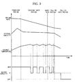
- FIG. 3 is a graph illustrating a first profile of heater control based on internal humidity of the drum and exhaust temperature during a drying operation of the clothing dryer according to the embodiment of the present invention.
- the controller 110 controls both the first and second hot air heaters 36 and 38 to be operated with the maximum heater capacity (M+N: 100%) in the transient drying period (approximately 5 minutes or less) in which clothing starts to be dried to increase temperature of air in the drum 30, the clothing and the surroundings of the clothing such that the clothing dryer 10 reaches an optimized drying state within a short time.
- M+N maximum heater capacity
- the controller 110 controls the first hot air heater 36 having the relatively large capacity M to be turned on/off according to the temperature of the exhaust air, i.e., exhaust temperature having a control temperature period set to uniformly maintain the exhaust air, and the second hot air heater 38 having the relatively small capacity N to be continuously on in the constant rate drying period in which main drying is performed such that the moisture contained in the clothing is removed within a short time.
- the humidity change amount (the drying rate) is uniformly maintained.
- the controller 110 determines the period at that time is the quasi-falling rate drying period and controls the first hot air heater 36 to be stopped. Upon determining that any control temperature period is the quasi-falling rate drying period, the controller 110 controls the first hot air heater 36 having the relatively large capacity M to be stopped.
- the controller 110 controls the second hot air heater 38 alone to be operated in the falling rate drying period (from approximately 22 minutes to the point of time at which drying is ended) corresponding to the second half of the drying period. Consequently, the drying of the clothing containing little moisture is completed using the relatively small heater capacity N, with the result that the internal temperature of the drum 30 is prevented from being excessively increased.
- FIG. 4 is a graph illustrating a second profile of heater control based on internal humidity of the drum and exhaust temperature during a drying operation of the clothing dryer according to the embodiment of the present invention. A repetitive description of the same portion as in FIG. 3 is omitted.
- the controller 110 controls both the first and second hot air heaters 36 and 38 to be operated with the maximum heater capacity (M+N: 100%) in the transient drying period such that the clothing dryer 10 reaches an optimized drying state within a short time.
- the controller 110 controls both the first and second hot air heaters 36 and 38 to be turned on/off according to the temperature of the exhaust air, i.e., exhaust temperature having a control temperature period set to uniformly maintain the exhaust air, in the constant rate drying period in which main drying is performed such that the moisture contained in the clothing is removed within a short time. At this time, the humidity change amount (the drying rate) is uniformly maintained.
- the controller 110 determines that the period at that time is the quasi-falling rate drying period and controls the first hot air heater 36 to be stopped.
- FIG. 5 is a graph illustrating a third profile of heater control based on internal humidity of the drum and exhaust temperature during a drying operation of the clothing dryer according to the embodiment of the present invention. A repetitive description of the same portion as in FIGS. 3 and 4 is omitted.
- the controller 110 controls both the first and second hot air heaters 36 and 38 to be operated with the maximum heater capacity (M+N: 100%) in the transient drying period such that the clothing dryer 10 reaches an optimized drying state within a short time.
- the controller 110 controls both the first and second hot air heaters 36 and 38 to be operated with the maximum heater capacity (M+N: 100%) in the constant rate drying period in which main drying is performed such that the moisture contained in the clothing is removed within a short time. At this time, the humidity change amount (the drying rate) is uniformly maintained.
- the controller 110 determines that the period at that time is the quasi-falling rate drying period and controls the first hot air heater 36 to be stopped.
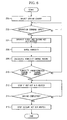
- FIG. 6 is a flow chart illustrating a control method of the clothing dryer according to an embodiment.
- operation information selected by the user is input to the controller 110 through the input unit 100.
- the controller 110 controls drying to be performed according to the operation information input through the input unit 100. First, the controller determines whether an operation command has been input (202).
- the controller 110 drives the motor 80 through the drive unit 120 and controls the first and second hot air heaters 36 and 38 to be operated according to the control profiles shown in FIGS. 3 to 5 (204).
- the drum 30 is rotated to rotate the clothing in the drum 30 according to the driving of the motor 80.
- the blowing fan 73 is also rotated according to the driving of the motor 80. As a result, air starts to flow in the clothing dryer 10.
- the first and second hot air heaters 36 and 38 are operated to heat the air flowing in the clothing dryer 10 into hot air according to the control profiles shown in FIGS. 3 to 5 .
- the hot air is supplied into the drum 30 through the intake duct 35.
- the hot air supplied into the drum 30 contacts the clothing rotated in the drum 30 while being repeatedly raised and lowered to dry the clothing through a drying operation to evaporate moisture contained in the clothing.
- Internal humidity of the drum 30 is decreased by the drying operation. At this time, the internal humidity of the drum 30 is sensed by the humidity sensor 61. The sensed internal humidity of the drum 30 is input to the controller 110 (206).
- the controller 110 calculates a humidity change amount based on the internal humidity of the drum 30 sensed by the humidity sensor 61 (208).
- the heat energy generated from the first and second hot air heaters 36 and 38 is used to evaporate moisture contained in the clothing, with the result that the drying rate is uniform.
- the heat energy generated from the first and second hot air heaters 36 and 38 is used to evaporate the moisture contained in the clothing in the constant rate drying period, with the result that the temperature of exhaust air having passed through the drum 30 is not suddenly increased by latent heat, and the humidity change amount is not also suddenly decreased.
- the controller 110 compares the calculated humidity change amount with a predetermined change amount (a humidity change amount in a predetermined percentage zone in which internal humidity of the drum is suddenly decreased) (210). Upon determining that the humidity change amount is not greater than the predetermined change amount, the procedure returns to Operation 204 where subsequent operations are performed.
- a predetermined change amount a humidity change amount in a predetermined percentage zone in which internal humidity of the drum is suddenly decreased
- the controller determines that the period at that time is the quasi-falling rate drying period in which the internal humidity of the drum 30 is suddenly decreased and stops the operation of the first hot air heater 36 through the drive unit 120 (212).
- the second hot air heater 38 alone is operated in a subsequent drying period. Since little moisture is present in the clothing at this time, the drying operation is performed with even the small capacity of the second hot air heater 38, with the result that power consumption is reduced. Also, the first and second hot air heaters 36 and 38 are not frequently turned on/off, with the result that the internal temperature of the drum 30 is uniformly maintained, thereby improving drying quality of the clothing.
- the controller 110 determines whether a drying completion condition has been satisfied (214). Upon determining that the drying completion condition has not been satisfied, the procedure returns to Operation 210 where subsequent operations are performed.
- the controller 110 Upon determining at Operation 214 that that the drying completion condition has been satisfied, the controller 110 stops the operation of the second hot air heater 38 through the drive unit 120 to complete the drying operation (216).
- the drying completion condition may be set as follows.
- the humidity sensor 61 contacts the clothing rotated according to the rotation of the drum 30 to generate an electric signal according to the amount of moisture contained in the clothing, based on which dryness of the clothing is determined.
- the determination of the quasi-falling rate drying period using the humidity change amount in the drum 30 has been described as an example.
- embodiments of the present invention are not limited thereto.
- the determination of the quasi-falling rate drying period using an increase rate in temperature of air discharged from the outlet of the drum 30 after drying the clothing, i.e., exhaust air may achieve the same effects.
- the operation of the heaters having different capacities is controlled to adjust heater capacity based on the humidity change amount (the drying rate), thereby reducing power consumption.
Landscapes
- Engineering & Computer Science (AREA)
- Textile Engineering (AREA)
- Control Of Washing Machine And Dryer (AREA)
- Drying Of Solid Materials (AREA)
- Detail Structures Of Washing Machines And Dryers (AREA)
Description
- Embodiments relate to a clothing dryer and a control method thereof that reduces power consumption without increasing drying time.
- Generally, a clothing dryer is an apparatus that supplies hot air heated by a hot air heater into a drum having clothing to be dried placed therein during the rotation of the drum to dry the clothing. The clothing dryer may be classified as an exhaust type clothing dryer in which high-temperature and high-humidity air, having passed through the drum, is discharged out of the clothing dryer or a condensing type clothing dryer in which moisture is removed from high-temperature and high-humidity air, having passed through the drum, and the air is supplied into the drum.
- In the clothing dryer, the hot air heater to heat air is turned on/off based on dryness of the clothing, internal humidity of the drum, temperature of air (exhaust air) discharged from the outlet of the drum after drying the clothing, etc. However, the hot air heater is controlled to maintain a predetermined temperature period until the drying is completed, with the result that excessive energy is consumed in a second half of a drying period, thereby lowering energy efficiency.
-
EP 0388939 A1 discloses a dryer with a drum and at least two electric heaters which have different working powers. Those heaters might be operated or stopped. Temperature and humidity are detected with a temperature sensor and a humidity sensor. The drying of the clothes dryer is controlled based on the measures humidity values. There is a maximum value of the absolute humidity wherein this absolute humidity value decreases during drying up to a particular predetermined value and then drying operation is stopped. - It is an object of the present application to provide a clothing dryer and a control method thereof that adjusts a heater capacity based on a humidity change amount (a drying rate) in a part of a drying period to reduce power consumption, in particular in a period in which internal humidity of a drum is suddenly decreased to reduce power consumption.
- Additional aspects will be set forth in part in the description which follows and, in part, will be apparent from the description, or may be learned by practice of the invention.
- This object is solved by the features of the independent claims.
- Advantageous embodiments are disclosed by the subclaims.
- The controller controls both the first and second hot air heaters to be operated when the humidity change amount is not greater than the predetermined change amount.
- The clothing dryer further includes a temperature sensor to sense exhaust temperature at an outlet of the drum, and the controller controls the first and second hot air heaters to be selectively operated based on the exhaust temperature when the humidity change amount is not greater than the predetermined change amount.
- The controller may control both the first and second hot air heaters to be turned on/off based on the exhaust temperature.
- The controller may control one of the first and second hot air heaters to be turned on and the other of the first and second hot air heaters to be turned on/off based on the exhaust temperature.
- The predetermined humidity range may be a range in which the internal humidity of the drum starts to suddenly decrease.
- The controller may control both the first and second hot air heaters to be operated when the internal humidity of the drum has not reached the predetermined humidity range.
- The clothing dryer may further include a temperature sensor to sense exhaust temperature at an outlet of the drum, and the controller may control the first and second hot air heaters to be selectively operated based on the exhaust temperature when the internal humidity of the drum has not reached the predetermined humidity range.
- The control method may further include sensing exhaust temperature at an outlet of the drum and controlling the first and second hot air heaters to be selectively turned on/off based on the exhaust temperature when the humidity change amount is not greater than the predetermined change amount.
- These and/or other aspects will become apparent and more readily appreciated from the following description of the embodiments, taken in conjunction with the accompanying drawings of which:
-
FIG. 1 is a sectional view illustrating the structure of a clothing dryer according to an embodiment; -
FIG. 2 is a control configuration diagram of the clothing dryer according to the embodiment; -
FIG. 3 is a graph illustrating a first profile of heater control based on internal humidity of a drum and exhaust temperature during a drying operation of the clothing dryer according to the embodiment; -
FIG. 4 is a graph illustrating a second profile of heater control based on internal humidity of the drum and exhaust temperature during a drying operation of the clothing dryer according to the embodiment; -
FIG. 5 is a graph illustrating a third profile of heater control based on internal humidity of the drum and exhaust temperature during a drying operation of the clothing dryer according to the embodiment; and -
FIG. 6 is a flow chart illustrating a control method of the clothing dryer according to an embodiment. - Reference will now be made in detail to the embodiments, examples of which are illustrated in the accompanying drawings, wherein like reference numerals refer to like elements throughout.
-
FIG. 1 is a sectional view illustrating the structure of aclothing dryer 10 according to an embodiment. - Referring to
FIG. 1 , theclothing dryer 10 includes ahousing 20 formed approximately in a hexahedral shape, thehousing 20 having throughholes 25 formed at the rear thereof to suction external air, acylindrical drum 30 mounted in thehousing 20, thecylindrical drum 30 being open at the front and rear thereof, afront bracket 31 and arear bracket 33 to slidably support the inner circumference of thedrum 30 at the front and rear ends thereof, respectively, andslide pads 40 mounted between thedrum 30 and thefront bracket 31 and between thedrum 30 and therear bracket 33 to assist smooth rotation of thedrum 30. - The
front bracket 31, mounted at the front of thedrum 30, is open at the center thereof such that clothing is introduced into thedrum 30 through the opening, which is closed bydoor 50. At the lower part of thedrum 30 is formed anexhaust port 60 through which air containing moisture evaporated from the clothing is discharged to the outside. - Inside the portion of the
drum 30 adjacent to theexhaust port 60 is mounted ahumidity sensor 61 to sense internal humidity of thedrum 30. Thehumidity sensor 61 contacts clothing rotated according to the rotation of thedrum 30 to generate an electric signal according to the amount of moisture contained in the clothing, based on which dryness of the clothing is determined. - Below the
drum 30 are mounted anexhaust duct 70, a blowingfan 73 and anexhaust pipe 76 to discharge air discharged from theexhaust port 60 out of theclothing dryer 10. In theexhaust duct 70 is mounted afilter 71 to filter impurities, such as dust or lint, contained in the air discharged from theexhaust port 60. Theexhaust duct 70 guides the air discharged from theexhaust port 60 to the lower part of thehousing 20. Theexhaust duct 70 is connected to the blowingfan 73 to generate force to induce flow of air in theclothing dryer 10. Air discharged by the blowingfan 73 is discharged to the outside through theexhaust pipe 76 having one end connected to afan casing 79 of the blowingfan 73 and the other end extending out of thehousing 20. In theexhaust pipe 76 is mounted anexhaust temperature sensor 77 to sense temperature of the air discharged from the outlet of thedrum 30 after drying clothing, i.e., exhaust temperature. - Below the
drum 30 is mounted amotor 80 to simultaneously drive the blowingfan 73 and thedrum 30. Themotor 80 has a drive shaft extending back and forth. One end of the drive shaft is connected to the blowingfan 73, and the other end of the drive shaft is connected to apulley 83 to drive thedrum 30. Thepulley 83 and thedrum 30 are connected to each other via abelt 86 such that thedrum 30 is rotated when themotor 80 is driven. - At the upper part of the
rear bracket 33, mounted at the rear of thedrum 30, are formedintake ports 34 to suction hot air. At the rear of therear bracket 33 is mounted anintake duct 35 to guide the hot air to theintake ports 34. Theintake duct 35 extends rearward from below thedrum 30 and is bent upward to communicate with theintake ports 34. At the inlet of theintake duct 35 are mounted first and secondhot air heaters housing 20. At the outlet of theintake duct 35 is mounted aheater temperature sensor 39 to sense temperature of the air having passed through the first and secondhot air heaters - The first and second
hot air heaters hot air heater 36 has a relatively large power capacity M of approximately 3.7 kW (70%), and the secondhot air heater 38 has a relatively small power capacity N of approximately 1.6 kW (30%). The power capacities of the first and secondhot air heaters hot air heater 38 has a variable power capacity N of approximately 1 to 2 kW. - In this embodiment, the clothing dryer is of an exhaust type although the clothing dryer may be of a condensing type.
-
FIG. 2 is a control configuration diagram of the clothing dryer according to the embodiment of the present invention. The clothing dryer includes aninput unit 100, acontroller 110 and adrive unit 120. - The
input unit 100 allows a user to input operation information, such as a drying course, drying time, and an operation command, to thecontroller 110. - The
controller 110 is a microprocessor to control overall operations of the clothing dryer according to the operation information input from theinput unit 100. Thecontroller 110 calculates a humidity change amount (a humidity change rate per predetermined time: a drying rate) based on internal humidity of thedrum 30 sensed by thehumidity sensor 61 and divides a drying period into several periods based on the calculated humidity change amount (the drying rate) to control a drying operation. - That is, the
controller 110 divides the drying period into a transient drying period, a constant rate drying period and a falling rate drying period based on the humidity change amount (the drying rate). - The transient drying period is an initial drying period in which clothing starts to be dried. In the transient drying period, temperature of air in the
drum 30, the clothing and the surroundings of the clothing is increased such that hot air heated by the first and secondhot air heaters - The constant rate drying period is a period in which main drying is performed. In the constant rate drying period, the hot air heated by the first and second
hot air heaters drum 30, i.e., the temperature of the exhaust air, has a constant temperature distribution. - The falling rate drying period is a period corresponding to a second half of a drying period in which drying is ended. In the falling rate drying period, less moisture is contained in the clothing than in the constant rate drying period, with the result that the hot air heated by the first and second
hot air heaters drum 30. Therefore, the temperature of the air at the outlet of thedrum 30, i.e., the temperature of exhaust air, has a suddenly rising temperature distribution. - Also, the
controller 110 controls only the secondhot air heater 38 having the relatively small capacity to be operated, such that the internal temperature of thedrum 30 is not excessively increased, at a point where the internal humidity of thedrum 30 is suddenly decreased in the falling rate drying period corresponding to the second half of the drying period. More specifically, upon determining that the humidity change amount in thedrum 30 is greater than a predetermined change amount as the result of the comparison therebetween, thecontroller 110 determines that the period at that time is a quasi-falling rate drying period in which the internal humidity of thedrum 30 starts to suddenly decrease and controls only the secondhot air heater 38 having the relatively small capacity to be operated. When the secondhot air heater 38 alone is operated, the clothing containing little moisture is sufficiently dried, and the internal temperature of thedrum 30 is maintained at a predetermined level or less. Consequently, the first and secondhot air heaters hot air heater 38 alone is continued until the drying is ended. - The
drive unit 120 operates the first and secondhot air heaters motor 80 according to a drive control signal from thecontroller 110. - Relations between the internal humidity of the
drum 30 and the control of the first and secondhot air heaters FIGS. 3 to 5 . -
FIG. 3 is a graph illustrating a first profile of heater control based on internal humidity of the drum and exhaust temperature during a drying operation of the clothing dryer according to the embodiment of the present invention. - As shown in
FIG. 3 , thecontroller 110 controls both the first and secondhot air heaters drum 30, the clothing and the surroundings of the clothing such that theclothing dryer 10 reaches an optimized drying state within a short time. - Subsequently, the
controller 110 controls the firsthot air heater 36 having the relatively large capacity M to be turned on/off according to the temperature of the exhaust air, i.e., exhaust temperature having a control temperature period set to uniformly maintain the exhaust air, and the secondhot air heater 38 having the relatively small capacity N to be continuously on in the constant rate drying period in which main drying is performed such that the moisture contained in the clothing is removed within a short time. At this time, the humidity change amount (the drying rate) is uniformly maintained. - When the moisture contained in the clothing in the
drum 30 is almost completely removed as the result of the drying operation in the constant rate drying period, the temperature of the air discharged from the outlet of thedrum 30 after drying the clothing, i.e., the exhaust temperature, is suddenly increased, with the result that the internal humidity of thedrum 30 is suddenly decreased. At this time, the humidity change amount is also decreased. Upon determining that the calculated humidity change amount is greater than the predetermined change amount as the result of the comparison therebetween, thecontroller 110 determines the period at that time is the quasi-falling rate drying period and controls the firsthot air heater 36 to be stopped. Upon determining that any control temperature period is the quasi-falling rate drying period, thecontroller 110 controls the firsthot air heater 36 having the relatively large capacity M to be stopped. - When the heater control is performed, such that the first
hot air heater 36 having the relatively large capacity M is stopped and the secondhot air heater 38 having the relative small capacity N is operated, before the quasi-falling rate drying period, drying time exceeds 30 minutes, and, when the heater control is performed, such that the secondhot air heater 38 alone is operated, after the quasi-falling rate drying period, a power consumption reduction rate is less than 5 %, which is confirmed through experiments as shown in Table 1 below. - Therefore, when the heater control is performed, such that the first
hot air heater 36 having the relatively large capacity M is stopped and the secondhot air heater 38 having the relative small capacity N is operated, in the quasi-falling rate drying period, power consumption is reduced without great increase of drying time, as confirmed by Table 1 below.[Table 1] Control time (min) Yearly power consumption (kWh/year) Drying time (min) Power consumption reduction rate (%) Drying time increment (%) 15 854.0 38 8.7 53.8 17 856.0 33.9 8.4 37.2 18 857.7 31.9 8.3 29.1 20 867.1 28.9 7.3 17.0 22 882.3 26 5.6 5.3 23 896.7 25.5 4.1 3.2 * Fundamental yearly power consumption: 935, drying time: 24.7 - In the state in which the first
hot air heater 36 is stopped in the quasi-falling rate drying period, thecontroller 110 controls the secondhot air heater 38 alone to be operated in the falling rate drying period (from approximately 22 minutes to the point of time at which drying is ended) corresponding to the second half of the drying period. Consequently, the drying of the clothing containing little moisture is completed using the relatively small heater capacity N, with the result that the internal temperature of thedrum 30 is prevented from being excessively increased. -
FIG. 4 is a graph illustrating a second profile of heater control based on internal humidity of the drum and exhaust temperature during a drying operation of the clothing dryer according to the embodiment of the present invention. A repetitive description of the same portion as inFIG. 3 is omitted. - As shown in
FIG. 4 , thecontroller 110 controls both the first and secondhot air heaters clothing dryer 10 reaches an optimized drying state within a short time. - Subsequently, the
controller 110 controls both the first and secondhot air heaters - When the moisture contained in the clothing in the
drum 30 is almost completely removed as the result of the drying operation in the constant rate drying period, the humidity change amount is suddenly decreased. Upon determining that the humidity change amount is greater than the predetermined change amount, thecontroller 110 determines that the period at that time is the quasi-falling rate drying period and controls the firsthot air heater 36 to be stopped. - When the heater control is performed, such that the first
hot air heater 36 having the relatively large capacity M is stopped and the secondhot air heater 38 having the relative small capacity N is operated, in the quasi-falling rate drying period, power consumption is reduced without great increase of drying time, as confirmed by Table 1 above. -
FIG. 5 is a graph illustrating a third profile of heater control based on internal humidity of the drum and exhaust temperature during a drying operation of the clothing dryer according to the embodiment of the present invention. A repetitive description of the same portion as inFIGS. 3 and4 is omitted. - As shown in
FIG. 5 , thecontroller 110 controls both the first and secondhot air heaters clothing dryer 10 reaches an optimized drying state within a short time. - Subsequently, the
controller 110 controls both the first and secondhot air heaters - When the moisture contained in the clothing in the
drum 30 is almost removed as the result of the drying operation in the constant rate drying period, the humidity change amount is suddenly decreased. Upon determining that the humidity change amount is greater than the predetermined change amount, thecontroller 110 determines that the period at that time is the quasi-falling rate drying period and controls the firsthot air heater 36 to be stopped. - When the heater control is performed, such that the first
hot air heater 36 having the relatively large capacity M is stopped and the secondhot air heater 38 having the relative small capacity N is operated, in the quasi-falling rate drying period, power consumption is reduced without great increase of drying time, as confirmed by Table 1 above. - Hereinafter, the operation of the clothing dryer according to the embodiment will be described.
-
FIG. 6 is a flow chart illustrating a control method of the clothing dryer according to an embodiment. - When a user puts clothing to be dried in the
drum 30 and selects a drying course according to kinds of the clothing (200), operation information selected by the user is input to thecontroller 110 through theinput unit 100. - The
controller 110 controls drying to be performed according to the operation information input through theinput unit 100. First, the controller determines whether an operation command has been input (202). - Upon determining at
Operation 202 that the operation command has been input, thecontroller 110 drives themotor 80 through thedrive unit 120 and controls the first and secondhot air heaters FIGS. 3 to 5 (204). - The
drum 30 is rotated to rotate the clothing in thedrum 30 according to the driving of themotor 80. The blowingfan 73 is also rotated according to the driving of themotor 80. As a result, air starts to flow in theclothing dryer 10. - At this time, the first and second
hot air heaters clothing dryer 10 into hot air according to the control profiles shown inFIGS. 3 to 5 . The hot air is supplied into thedrum 30 through theintake duct 35. The hot air supplied into thedrum 30 contacts the clothing rotated in thedrum 30 while being repeatedly raised and lowered to dry the clothing through a drying operation to evaporate moisture contained in the clothing. - Internal humidity of the
drum 30 is decreased by the drying operation. At this time, the internal humidity of thedrum 30 is sensed by thehumidity sensor 61. The sensed internal humidity of thedrum 30 is input to the controller 110 (206). - The
controller 110 calculates a humidity change amount based on the internal humidity of thedrum 30 sensed by the humidity sensor 61 (208). - In the transient drying period in which the clothing starts to be dried, heat energy generated from the first and second
hot air heaters drum 30, the clothing and the surroundings of the clothing although both the first and secondhot air heaters - On the other hand, in the constant rate drying period in which main drying is performed, the heat energy generated from the first and second
hot air heaters - In this way, the heat energy generated from the first and second
hot air heaters drum 30 is not suddenly increased by latent heat, and the humidity change amount is not also suddenly decreased. - When the moisture contained in the clothing is almost removed, however, the temperature of the exhaust air having passed through the
drum 30 is suddenly increased, and the humidity change amount is also suddenly decreased. - Consequently, the
controller 110 compares the calculated humidity change amount with a predetermined change amount (a humidity change amount in a predetermined percentage zone in which internal humidity of the drum is suddenly decreased) (210). Upon determining that the humidity change amount is not greater than the predetermined change amount, the procedure returns toOperation 204 where subsequent operations are performed. - Upon determining at
Operation 210 that the humidity change amount is greater than the predetermined change amount, the controller determines that the period at that time is the quasi-falling rate drying period in which the internal humidity of thedrum 30 is suddenly decreased and stops the operation of the firsthot air heater 36 through the drive unit 120 (212). - Consequently, the second
hot air heater 38 alone is operated in a subsequent drying period. Since little moisture is present in the clothing at this time, the drying operation is performed with even the small capacity of the secondhot air heater 38, with the result that power consumption is reduced. Also, the first and secondhot air heaters drum 30 is uniformly maintained, thereby improving drying quality of the clothing. - Subsequently, the
controller 110 determines whether a drying completion condition has been satisfied (214). Upon determining that the drying completion condition has not been satisfied, the procedure returns toOperation 210 where subsequent operations are performed. - Upon determining at
Operation 214 that that the drying completion condition has been satisfied, thecontroller 110 stops the operation of the secondhot air heater 38 through thedrive unit 120 to complete the drying operation (216). The drying completion condition may be set as follows. Thehumidity sensor 61 contacts the clothing rotated according to the rotation of thedrum 30 to generate an electric signal according to the amount of moisture contained in the clothing, based on which dryness of the clothing is determined. - In this embodiment, the determination of the quasi-falling rate drying period using the humidity change amount in the
drum 30 has been described as an example. However, embodiments of the present invention are not limited thereto. For example, the determination of the quasi-falling rate drying period using an increase rate in temperature of air discharged from the outlet of thedrum 30 after drying the clothing, i.e., exhaust air may achieve the same effects. - As is apparent from the above description, the operation of the heaters having different capacities is controlled to adjust heater capacity based on the humidity change amount (the drying rate), thereby reducing power consumption.
- Also, only the heater having the relatively small capacity is operated in the period in which the internal humidity of the drum is suddenly decreased, thereby reducing power consumption without great increase of drying time.
- Although a few embodiments have been shown and described, it would be appreciated by those skilled in the art that changes may be made in these embodiments without departing from the principles of the invention, the scope of which is defined in the claims.
Claims (8)
- A clothing dryer (10) comprising:a drum (30) to receive clothing;at least two hot air heaters (36, 38) to supply hot air into the drum (30);a humidity sensor (61) to sense internal humidity of the drum; anda controller (110),said hot air heaters (36, 38) comprise a first hot air heater (36) with a higher heat capacity than a second hot air heater,
said controller (110) is adapted to calculate a humidity change amount in the drum (30), to compare the calculated humidity change amount with a predetermined change amount, and to control the first or second air heater (36, 38) to be operated to adjust a heater capacity characterized in that it stops the operation of the first air heater (36), in a falling rate drying period in which the humidity change amount is greater than the predetermined change amount. - The clothing dryer according to claim 1, wherein the controller (110) controls both the first and second hot air heaters (36,38) to be operated when the humidity change amount is not greater than the predetermined change amount.
- The clothing dryer according to claim 1, further comprising:a temperature sensor (77) to sense exhaust temperature at an outlet of the drum (30), whereinthe controller (110) controls the first and second hot air heaters (36,38) to be selectively operated based on the exhaust temperature when the humidity change amount is not greater than the predetermined change amount.
- The clothing dryer according to claim 3, wherein the controller (110) controls both the first and second hot air heaters (36,38) to be turned on/off based on the exhaust temperature.
- The clothing dryer according to claim 3, wherein the controller (110) controls one of the first and second hot air heaters (36,38) to be turned on and the other of the first and second hot air heaters to be turned on/off based on the exhaust temperature.
- A control method of a clothing dryer (10) comprising a drum (30) and at least a first and a second hot air heater (36, 38) from which the first hot air heater (36) has a higher heat capacity than the second hot air heater (38), to supply hot air into the drum, the control method comprising:a) determining (200, 202) whether a drying course has been selected;, andb) turning (304) on/off the hot air heaters (36, 38) to perform a drying operation upon determining that the drying course has been selected, andwith the further steps ofi) sensing (206) changes in internal humidity of the drum during the drying operation;ii) calculating (208) a humidity change amount in the drum; andiii) comparing (210) the calculated humidity change amount with a predetermined change amount and controlling a first or second air heater (36, 38) to be operated to adjust a heater capacity and to stop the operation of the first air heater (36) in a falling rate drying period in which the humidity change amount is greater than the predetermined change amount.
- The control method according to claim 6, further comprising controlling both the first and second hot air heaters (36,38) to be operated when the humidity change amount is not greater than the predetermined change amount.
- The control method according to claim 6, further comprising:sensing exhaust temperature at an outlet of the drum (30); andcontrolling the first and second hot air heaters (36,38) to be selectively turned on/off based on the exhaust temperature when the humidity change amount is not greater than the predetermined change amount.
Applications Claiming Priority (1)
| Application Number | Priority Date | Filing Date | Title |
|---|---|---|---|
| KR1020100000939A KR20110080620A (en) | 2010-01-06 | 2010-01-06 | Dryer and its control method |
Publications (2)
| Publication Number | Publication Date |
|---|---|
| EP2343412A1 EP2343412A1 (en) | 2011-07-13 |
| EP2343412B1 true EP2343412B1 (en) | 2016-08-17 |
Family
ID=43928133
Family Applications (1)
| Application Number | Title | Priority Date | Filing Date |
|---|---|---|---|
| EP10191620.3A Not-in-force EP2343412B1 (en) | 2010-01-06 | 2010-11-18 | Clothing dryer and control method thereof |
Country Status (4)
| Country | Link |
|---|---|
| US (2) | US9091014B2 (en) |
| EP (1) | EP2343412B1 (en) |
| KR (1) | KR20110080620A (en) |
| CN (2) | CN104894822B (en) |
Cited By (1)
| Publication number | Priority date | Publication date | Assignee | Title |
|---|---|---|---|---|
| US11060236B2 (en) * | 2019-10-03 | 2021-07-13 | Haier Us Appliance Solutions, Inc. | Dryer appliance and method of operating the same based on the relative humidity of drum exit air |
Families Citing this family (32)
| Publication number | Priority date | Publication date | Assignee | Title |
|---|---|---|---|---|
| JP2012055400A (en) * | 2010-09-07 | 2012-03-22 | Panasonic Corp | Clothes dryer |
| KR101878445B1 (en) * | 2011-12-30 | 2018-07-16 | 삼성전자주식회사 | Clothes dryer and control method thereof |
| US9481777B2 (en) | 2012-03-30 | 2016-11-01 | The Procter & Gamble Company | Method of dewatering in a continuous high internal phase emulsion foam forming process |
| JP6089202B2 (en) * | 2012-09-20 | 2017-03-08 | パナソニックIpマネジメント株式会社 | Dehumidifier |
| CN103321028A (en) * | 2013-06-26 | 2013-09-25 | 无锡小天鹅股份有限公司 | Control device and control method for clothes dryer |
| MX358870B (en) * | 2014-04-16 | 2018-09-04 | Mabe Sa De Cv | Intelligent electronic system for previously sensing the dryness condition of a textile clothes load in an automatic electronic clothes dryer machine. |
| CN104452227B (en) * | 2014-12-26 | 2016-08-03 | 东华大学 | Fabric drying degree dual automatic measuring and controlling platform and method thereof in a kind of dryer |
| KR101661994B1 (en) * | 2015-01-30 | 2016-10-04 | 엘지전자 주식회사 | Washing and drying system |
| US10138590B2 (en) * | 2015-03-20 | 2018-11-27 | Whirlpool Corporation | Method for drying laundry in a laundry treating appliance |
| CN106319825A (en) * | 2015-06-25 | 2017-01-11 | 青岛海尔洗衣机有限公司 | A clothes dryer/washing and drying integrated machine control method |
| CN106498678B (en) * | 2015-09-07 | 2020-10-20 | 青岛海尔洗衣机有限公司 | Clothes dryer control method |
| CN106841302B (en) * | 2016-12-29 | 2020-04-10 | 无锡小天鹅电器有限公司 | Clothes drying equipment and clothes drying humidity judging method and device for same |
| KR102138677B1 (en) * | 2017-04-18 | 2020-07-29 | 주식회사 에어로네트 | Negative-pressure, Air-jet Clothes Dryer Control Method |
| JP6615966B1 (en) * | 2018-06-29 | 2019-12-04 | 株式会社日本輸出自動車検査センター | Automotive high temperature pest control equipment |
| CN108968763B (en) * | 2018-07-05 | 2024-05-31 | 深圳和而泰智能家电控制器有限公司 | A control method for smart toilet and smart toilet |
| CN110878470A (en) * | 2018-08-27 | 2020-03-13 | 无锡小天鹅电器有限公司 | Control method and device of clothes treatment device and clothes treatment device |
| KR102862653B1 (en) | 2019-10-25 | 2025-09-23 | 삼성전자주식회사 | Dryer and controlling method thereof |
| KR102838697B1 (en) * | 2019-11-21 | 2025-07-28 | 삼성전자주식회사 | Dryer and method for controlling the same |
| CN112853712B (en) * | 2019-11-26 | 2025-01-17 | 天津海尔洗涤电器有限公司 | Control method of laundry treating apparatus |
| CN112252002B (en) * | 2020-09-21 | 2021-12-07 | 珠海格力电器股份有限公司 | Drying method and device of washing and drying machine |
| CN112176681A (en) * | 2020-09-28 | 2021-01-05 | 珠海格力电器股份有限公司 | Clothes treatment device, control method of clothes treatment device, control device and control system |
| CN112962278B (en) * | 2020-11-20 | 2023-08-01 | 吉智(宁波)智能科技有限公司 | Control method of washing and protecting system with drying device |
| EP4166709A4 (en) * | 2020-11-20 | 2023-12-27 | Samsung Electronics Co., Ltd. | Dryer and method for controlling same |
| CN116583639A (en) * | 2020-11-20 | 2023-08-11 | 三星电子株式会社 | Clothes dryer and method for controlling same |
| CN112760957B (en) * | 2020-12-11 | 2021-12-24 | 珠海格力电器股份有限公司 | Control method and device of dryer, storage medium and processor |
| CN112853711A (en) * | 2021-01-08 | 2021-05-28 | 珠海格力电器股份有限公司 | Heating and drying control method for clothes processing device and clothes dryer thereof |
| CN113417123A (en) * | 2021-07-23 | 2021-09-21 | 珠海格力电器股份有限公司 | Clothes drying control method, clothes dryer and storage medium |
| KR20230032179A (en) * | 2021-08-30 | 2023-03-07 | 삼성전자주식회사 | Dryer and controlling method thereof |
| CN113897765A (en) * | 2021-11-15 | 2022-01-07 | 木卫智能科技(深圳)有限公司 | Control method of clothes treatment equipment and clothes treatment equipment |
| EP4715103A3 (en) | 2021-12-30 | 2026-04-15 | Samsung Electronics Co., Ltd. | Washing machine with drying function |
| CN114481578B (en) * | 2022-01-24 | 2022-12-09 | 珠海格力电器股份有限公司 | Heat pump clothes dryer control method and device and heat pump clothes dryer |
| KR102717192B1 (en) * | 2023-08-18 | 2024-10-11 | 이은정 | Dryer and control method thereof |
Family Cites Families (15)
| Publication number | Priority date | Publication date | Assignee | Title |
|---|---|---|---|---|
| JPS59197297A (en) | 1983-04-25 | 1984-11-08 | 松下電器産業株式会社 | Controller of dryer |
| JPS59197300A (en) | 1983-04-25 | 1984-11-08 | 松下電器産業株式会社 | dryer control device |
| JPS59197298A (en) | 1983-04-25 | 1984-11-08 | 松下電器産業株式会社 | dryer control device |
| DE69002494T2 (en) | 1989-03-24 | 1993-11-25 | Sanyo Electric Co | Method and device for controlling a clothes dryer. |
| JP2000005493A (en) | 1998-06-19 | 2000-01-11 | Hitachi Ltd | Drying operation control device for clothes dryer |
| KR100461637B1 (en) * | 2001-10-25 | 2004-12-14 | 주식회사 엘지이아이 | Method and device for controlling heater in dryer |
| JP2005506165A (en) * | 2001-10-25 | 2005-03-03 | エルジー エレクトロニクス インコーポレイテッド | Dryer and drying control method therefor |
| KR20040100894A (en) | 2003-05-21 | 2004-12-02 | 산요덴키가부시키가이샤 | Washing machine with clothes dry function |
| KR20050089343A (en) * | 2004-03-04 | 2005-09-08 | 주식회사 대우일렉트로닉스 | Method for controlling the drying stage of drum washing machine |
| CN1724801A (en) | 2004-07-19 | 2006-01-25 | 乐金电子(天津)电器有限公司 | Condensing clothes drying machine and its drying region separation method |
| CN1727564A (en) | 2004-07-26 | 2006-02-01 | 乐金电子(天津)电器有限公司 | Drying control method for clothings drier |
| US7080464B1 (en) * | 2005-01-10 | 2006-07-25 | Whirlpool Corporation | Detection of synthetic fabric loads in an automatic dryer |
| CN101146948B (en) * | 2005-03-22 | 2011-01-26 | 阿塞里克股份有限公司 | A washer/dryer and the control method |
| KR100811487B1 (en) | 2007-02-13 | 2008-03-07 | 엘지전자 주식회사 | Ductless dryer |
| KR101256146B1 (en) * | 2007-12-27 | 2013-04-23 | 동부대우전자 주식회사 | Method controlling heater of dryer having indrawn tube built in heater |
-
2010
- 2010-01-06 KR KR1020100000939A patent/KR20110080620A/en not_active Ceased
- 2010-11-04 US US12/926,261 patent/US9091014B2/en not_active Expired - Fee Related
- 2010-11-18 EP EP10191620.3A patent/EP2343412B1/en not_active Not-in-force
- 2010-12-03 CN CN201510338805.1A patent/CN104894822B/en not_active Expired - Fee Related
- 2010-12-03 CN CN201010579642.3A patent/CN102115972B/en not_active Expired - Fee Related
-
2015
- 2015-06-30 US US14/755,477 patent/US20150299935A1/en not_active Abandoned
Cited By (1)
| Publication number | Priority date | Publication date | Assignee | Title |
|---|---|---|---|---|
| US11060236B2 (en) * | 2019-10-03 | 2021-07-13 | Haier Us Appliance Solutions, Inc. | Dryer appliance and method of operating the same based on the relative humidity of drum exit air |
Also Published As
| Publication number | Publication date |
|---|---|
| EP2343412A1 (en) | 2011-07-13 |
| CN102115972B (en) | 2015-08-05 |
| US20150299935A1 (en) | 2015-10-22 |
| CN104894822A (en) | 2015-09-09 |
| CN104894822B (en) | 2017-07-28 |
| KR20110080620A (en) | 2011-07-13 |
| US9091014B2 (en) | 2015-07-28 |
| US20110162228A1 (en) | 2011-07-07 |
| CN102115972A (en) | 2011-07-06 |
Similar Documents
| Publication | Publication Date | Title |
|---|---|---|
| US9091014B2 (en) | Clothing dryer and control method thereof | |
| EP2436833A1 (en) | Clothes dryer | |
| CA2446359C (en) | Clothes dryer apparatus and method | |
| US20070251119A1 (en) | Dryer and control method thereof | |
| CN111344450B (en) | Control method of dryer | |
| CA2753314C (en) | Clothes dryer apparatus and method | |
| EP1688532B1 (en) | Automatic clothes dryer | |
| US12188172B2 (en) | Laundry treating apparatus | |
| CN106592185A (en) | Drying device, and control method and control system thereof | |
| US8991068B2 (en) | Energy efficient cycle for clothes dryer | |
| US7644513B2 (en) | Laundry dryer and method for controlling drying course of the same | |
| US20050252028A1 (en) | Control method of clothes dryer and apparatus thereof | |
| US20250154713A1 (en) | Laundry treating apparatus | |
| US20050132599A1 (en) | Drying method of washing machine and apparatus thereof | |
| JP5884673B2 (en) | Grain dryer | |
| KR101452161B1 (en) | Drying method for agricultural products using drier of agricultural products | |
| KR20190057659A (en) | Control method for drying machine | |
| JP2007010247A (en) | Grain dryer | |
| CN210737169U (en) | Clothes dryer | |
| US20090165331A1 (en) | Method of controlling heat in dryer having intake duct with builtin heater | |
| KR0141778B1 (en) | Dehumidifying clothes dryer with air volume control | |
| CN100519913C (en) | Clothes drier and its control method | |
| KR101314241B1 (en) | Washing Machine | |
| KR20030009960A (en) | Control method for dryer | |
| KR20110045756A (en) | Outage compensation control method of clothes dryer |
Legal Events
| Date | Code | Title | Description |
|---|---|---|---|
| PUAI | Public reference made under article 153(3) epc to a published international application that has entered the european phase |
Free format text: ORIGINAL CODE: 0009012 |
|
| AK | Designated contracting states |
Kind code of ref document: A1 Designated state(s): AL AT BE BG CH CY CZ DE DK EE ES FI FR GB GR HR HU IE IS IT LI LT LU LV MC MK MT NL NO PL PT RO RS SE SI SK SM TR |
|
| AX | Request for extension of the european patent |
Extension state: BA ME |
|
| 17P | Request for examination filed |
Effective date: 20120112 |
|
| RAP1 | Party data changed (applicant data changed or rights of an application transferred) |
Owner name: SAMSUNG ELECTRONICS CO., LTD. |
|
| 17Q | First examination report despatched |
Effective date: 20121220 |
|
| GRAP | Despatch of communication of intention to grant a patent |
Free format text: ORIGINAL CODE: EPIDOSNIGR1 |
|
| INTG | Intention to grant announced |
Effective date: 20160308 |
|
| GRAS | Grant fee paid |
Free format text: ORIGINAL CODE: EPIDOSNIGR3 |
|
| GRAA | (expected) grant |
Free format text: ORIGINAL CODE: 0009210 |
|
| AK | Designated contracting states |
Kind code of ref document: B1 Designated state(s): AL AT BE BG CH CY CZ DE DK EE ES FI FR GB GR HR HU IE IS IT LI LT LU LV MC MK MT NL NO PL PT RO RS SE SI SK SM TR |
|
| REG | Reference to a national code |
Ref country code: GB Ref legal event code: FG4D |
|
| REG | Reference to a national code |
Ref country code: CH Ref legal event code: EP |
|
| REG | Reference to a national code |
Ref country code: IE Ref legal event code: FG4D |
|
| REG | Reference to a national code |
Ref country code: AT Ref legal event code: REF Ref document number: 821216 Country of ref document: AT Kind code of ref document: T Effective date: 20160915 |
|
| REG | Reference to a national code |
Ref country code: DE Ref legal event code: R096 Ref document number: 602010035552 Country of ref document: DE |
|
| REG | Reference to a national code |
Ref country code: NL Ref legal event code: MP Effective date: 20160817 |
|
| REG | Reference to a national code |
Ref country code: LT Ref legal event code: MG4D |
|
| REG | Reference to a national code |
Ref country code: AT Ref legal event code: MK05 Ref document number: 821216 Country of ref document: AT Kind code of ref document: T Effective date: 20160817 |
|
| PG25 | Lapsed in a contracting state [announced via postgrant information from national office to epo] |
Ref country code: IT Free format text: LAPSE BECAUSE OF FAILURE TO SUBMIT A TRANSLATION OF THE DESCRIPTION OR TO PAY THE FEE WITHIN THE PRESCRIBED TIME-LIMIT Effective date: 20160817 Ref country code: RS Free format text: LAPSE BECAUSE OF FAILURE TO SUBMIT A TRANSLATION OF THE DESCRIPTION OR TO PAY THE FEE WITHIN THE PRESCRIBED TIME-LIMIT Effective date: 20160817 Ref country code: LT Free format text: LAPSE BECAUSE OF FAILURE TO SUBMIT A TRANSLATION OF THE DESCRIPTION OR TO PAY THE FEE WITHIN THE PRESCRIBED TIME-LIMIT Effective date: 20160817 Ref country code: NL Free format text: LAPSE BECAUSE OF FAILURE TO SUBMIT A TRANSLATION OF THE DESCRIPTION OR TO PAY THE FEE WITHIN THE PRESCRIBED TIME-LIMIT Effective date: 20160817 Ref country code: NO Free format text: LAPSE BECAUSE OF FAILURE TO SUBMIT A TRANSLATION OF THE DESCRIPTION OR TO PAY THE FEE WITHIN THE PRESCRIBED TIME-LIMIT Effective date: 20161117 Ref country code: FI Free format text: LAPSE BECAUSE OF FAILURE TO SUBMIT A TRANSLATION OF THE DESCRIPTION OR TO PAY THE FEE WITHIN THE PRESCRIBED TIME-LIMIT Effective date: 20160817 Ref country code: HR Free format text: LAPSE BECAUSE OF FAILURE TO SUBMIT A TRANSLATION OF THE DESCRIPTION OR TO PAY THE FEE WITHIN THE PRESCRIBED TIME-LIMIT Effective date: 20160817 |
|
| PG25 | Lapsed in a contracting state [announced via postgrant information from national office to epo] |
Ref country code: ES Free format text: LAPSE BECAUSE OF FAILURE TO SUBMIT A TRANSLATION OF THE DESCRIPTION OR TO PAY THE FEE WITHIN THE PRESCRIBED TIME-LIMIT Effective date: 20160817 Ref country code: PL Free format text: LAPSE BECAUSE OF FAILURE TO SUBMIT A TRANSLATION OF THE DESCRIPTION OR TO PAY THE FEE WITHIN THE PRESCRIBED TIME-LIMIT Effective date: 20160817 Ref country code: SE Free format text: LAPSE BECAUSE OF FAILURE TO SUBMIT A TRANSLATION OF THE DESCRIPTION OR TO PAY THE FEE WITHIN THE PRESCRIBED TIME-LIMIT Effective date: 20160817 Ref country code: BE Free format text: LAPSE BECAUSE OF NON-PAYMENT OF DUE FEES Effective date: 20161130 Ref country code: LV Free format text: LAPSE BECAUSE OF FAILURE TO SUBMIT A TRANSLATION OF THE DESCRIPTION OR TO PAY THE FEE WITHIN THE PRESCRIBED TIME-LIMIT Effective date: 20160817 Ref country code: PT Free format text: LAPSE BECAUSE OF FAILURE TO SUBMIT A TRANSLATION OF THE DESCRIPTION OR TO PAY THE FEE WITHIN THE PRESCRIBED TIME-LIMIT Effective date: 20161219 Ref country code: GR Free format text: LAPSE BECAUSE OF FAILURE TO SUBMIT A TRANSLATION OF THE DESCRIPTION OR TO PAY THE FEE WITHIN THE PRESCRIBED TIME-LIMIT Effective date: 20161118 Ref country code: AT Free format text: LAPSE BECAUSE OF FAILURE TO SUBMIT A TRANSLATION OF THE DESCRIPTION OR TO PAY THE FEE WITHIN THE PRESCRIBED TIME-LIMIT Effective date: 20160817 |
|
| PG25 | Lapsed in a contracting state [announced via postgrant information from national office to epo] |
Ref country code: EE Free format text: LAPSE BECAUSE OF FAILURE TO SUBMIT A TRANSLATION OF THE DESCRIPTION OR TO PAY THE FEE WITHIN THE PRESCRIBED TIME-LIMIT Effective date: 20160817 Ref country code: RO Free format text: LAPSE BECAUSE OF FAILURE TO SUBMIT A TRANSLATION OF THE DESCRIPTION OR TO PAY THE FEE WITHIN THE PRESCRIBED TIME-LIMIT Effective date: 20160817 |
|
| REG | Reference to a national code |
Ref country code: DE Ref legal event code: R097 Ref document number: 602010035552 Country of ref document: DE |
|
| PG25 | Lapsed in a contracting state [announced via postgrant information from national office to epo] |
Ref country code: BG Free format text: LAPSE BECAUSE OF FAILURE TO SUBMIT A TRANSLATION OF THE DESCRIPTION OR TO PAY THE FEE WITHIN THE PRESCRIBED TIME-LIMIT Effective date: 20161117 Ref country code: CZ Free format text: LAPSE BECAUSE OF FAILURE TO SUBMIT A TRANSLATION OF THE DESCRIPTION OR TO PAY THE FEE WITHIN THE PRESCRIBED TIME-LIMIT Effective date: 20160817 Ref country code: SM Free format text: LAPSE BECAUSE OF FAILURE TO SUBMIT A TRANSLATION OF THE DESCRIPTION OR TO PAY THE FEE WITHIN THE PRESCRIBED TIME-LIMIT Effective date: 20160817 Ref country code: DK Free format text: LAPSE BECAUSE OF FAILURE TO SUBMIT A TRANSLATION OF THE DESCRIPTION OR TO PAY THE FEE WITHIN THE PRESCRIBED TIME-LIMIT Effective date: 20160817 Ref country code: BE Free format text: LAPSE BECAUSE OF FAILURE TO SUBMIT A TRANSLATION OF THE DESCRIPTION OR TO PAY THE FEE WITHIN THE PRESCRIBED TIME-LIMIT Effective date: 20160817 Ref country code: SK Free format text: LAPSE BECAUSE OF FAILURE TO SUBMIT A TRANSLATION OF THE DESCRIPTION OR TO PAY THE FEE WITHIN THE PRESCRIBED TIME-LIMIT Effective date: 20160817 |
|
| PLBE | No opposition filed within time limit |
Free format text: ORIGINAL CODE: 0009261 |
|
| STAA | Information on the status of an ep patent application or granted ep patent |
Free format text: STATUS: NO OPPOSITION FILED WITHIN TIME LIMIT |
|
| REG | Reference to a national code |
Ref country code: CH Ref legal event code: PL |
|
| 26N | No opposition filed |
Effective date: 20170518 |
|
| PG25 | Lapsed in a contracting state [announced via postgrant information from national office to epo] |
Ref country code: CH Free format text: LAPSE BECAUSE OF NON-PAYMENT OF DUE FEES Effective date: 20161130 Ref country code: LI Free format text: LAPSE BECAUSE OF NON-PAYMENT OF DUE FEES Effective date: 20161130 |
|
| REG | Reference to a national code |
Ref country code: IE Ref legal event code: MM4A |
|
| REG | Reference to a national code |
Ref country code: FR Ref legal event code: ST Effective date: 20170731 |
|
| PG25 | Lapsed in a contracting state [announced via postgrant information from national office to epo] |
Ref country code: SI Free format text: LAPSE BECAUSE OF FAILURE TO SUBMIT A TRANSLATION OF THE DESCRIPTION OR TO PAY THE FEE WITHIN THE PRESCRIBED TIME-LIMIT Effective date: 20160817 |
|
| PG25 | Lapsed in a contracting state [announced via postgrant information from national office to epo] |
Ref country code: LU Free format text: LAPSE BECAUSE OF NON-PAYMENT OF DUE FEES Effective date: 20161130 |
|
| PG25 | Lapsed in a contracting state [announced via postgrant information from national office to epo] |
Ref country code: FR Free format text: LAPSE BECAUSE OF NON-PAYMENT OF DUE FEES Effective date: 20161130 |
|
| PG25 | Lapsed in a contracting state [announced via postgrant information from national office to epo] |
Ref country code: IE Free format text: LAPSE BECAUSE OF NON-PAYMENT OF DUE FEES Effective date: 20161118 |
|
| PG25 | Lapsed in a contracting state [announced via postgrant information from national office to epo] |
Ref country code: CY Free format text: LAPSE BECAUSE OF FAILURE TO SUBMIT A TRANSLATION OF THE DESCRIPTION OR TO PAY THE FEE WITHIN THE PRESCRIBED TIME-LIMIT Effective date: 20160817 Ref country code: HU Free format text: LAPSE BECAUSE OF FAILURE TO SUBMIT A TRANSLATION OF THE DESCRIPTION OR TO PAY THE FEE WITHIN THE PRESCRIBED TIME-LIMIT; INVALID AB INITIO Effective date: 20101118 |
|
| PG25 | Lapsed in a contracting state [announced via postgrant information from national office to epo] |
Ref country code: MK Free format text: LAPSE BECAUSE OF FAILURE TO SUBMIT A TRANSLATION OF THE DESCRIPTION OR TO PAY THE FEE WITHIN THE PRESCRIBED TIME-LIMIT Effective date: 20160817 Ref country code: TR Free format text: LAPSE BECAUSE OF FAILURE TO SUBMIT A TRANSLATION OF THE DESCRIPTION OR TO PAY THE FEE WITHIN THE PRESCRIBED TIME-LIMIT Effective date: 20160817 Ref country code: IS Free format text: LAPSE BECAUSE OF FAILURE TO SUBMIT A TRANSLATION OF THE DESCRIPTION OR TO PAY THE FEE WITHIN THE PRESCRIBED TIME-LIMIT Effective date: 20160817 Ref country code: MC Free format text: LAPSE BECAUSE OF FAILURE TO SUBMIT A TRANSLATION OF THE DESCRIPTION OR TO PAY THE FEE WITHIN THE PRESCRIBED TIME-LIMIT Effective date: 20160817 |
|
| PG25 | Lapsed in a contracting state [announced via postgrant information from national office to epo] |
Ref country code: MT Free format text: LAPSE BECAUSE OF NON-PAYMENT OF DUE FEES Effective date: 20161118 |
|
| PG25 | Lapsed in a contracting state [announced via postgrant information from national office to epo] |
Ref country code: AL Free format text: LAPSE BECAUSE OF FAILURE TO SUBMIT A TRANSLATION OF THE DESCRIPTION OR TO PAY THE FEE WITHIN THE PRESCRIBED TIME-LIMIT Effective date: 20160817 |
|
| REG | Reference to a national code |
Ref country code: DE Ref legal event code: R079 Ref document number: 602010035552 Country of ref document: DE Free format text: PREVIOUS MAIN CLASS: D06F0058280000 Ipc: D06F0058300000 |
|
| PGFP | Annual fee paid to national office [announced via postgrant information from national office to epo] |
Ref country code: GB Payment date: 20231023 Year of fee payment: 14 |
|
| PGFP | Annual fee paid to national office [announced via postgrant information from national office to epo] |
Ref country code: DE Payment date: 20231023 Year of fee payment: 14 |
|
| REG | Reference to a national code |
Ref country code: DE Ref legal event code: R119 Ref document number: 602010035552 Country of ref document: DE |
|
| GBPC | Gb: european patent ceased through non-payment of renewal fee |
Effective date: 20241118 |
|
| PG25 | Lapsed in a contracting state [announced via postgrant information from national office to epo] |
Ref country code: DE Free format text: LAPSE BECAUSE OF NON-PAYMENT OF DUE FEES Effective date: 20250603 |
|
| PG25 | Lapsed in a contracting state [announced via postgrant information from national office to epo] |
Ref country code: GB Free format text: LAPSE BECAUSE OF NON-PAYMENT OF DUE FEES Effective date: 20241118 |