EP2343098A1 - Cathéter échogénique guidé par ultrasons et procédés correspondants - Google Patents
Cathéter échogénique guidé par ultrasons et procédés correspondants Download PDFInfo
- Publication number
- EP2343098A1 EP2343098A1 EP11150487A EP11150487A EP2343098A1 EP 2343098 A1 EP2343098 A1 EP 2343098A1 EP 11150487 A EP11150487 A EP 11150487A EP 11150487 A EP11150487 A EP 11150487A EP 2343098 A1 EP2343098 A1 EP 2343098A1
- Authority
- EP
- European Patent Office
- Prior art keywords
- catheter
- tube
- catheter tube
- cord
- lumen
- Prior art date
- Legal status (The legal status is an assumption and is not a legal conclusion. Google has not performed a legal analysis and makes no representation as to the accuracy of the status listed.)
- Withdrawn
Links
Images


Classifications
-
- A—HUMAN NECESSITIES
- A61—MEDICAL OR VETERINARY SCIENCE; HYGIENE
- A61M—DEVICES FOR INTRODUCING MEDIA INTO, OR ONTO, THE BODY; DEVICES FOR TRANSDUCING BODY MEDIA OR FOR TAKING MEDIA FROM THE BODY; DEVICES FOR PRODUCING OR ENDING SLEEP OR STUPOR
- A61M25/00—Catheters; Hollow probes
- A61M25/0009—Making of catheters or other medical or surgical tubes
- A61M25/0012—Making of catheters or other medical or surgical tubes with embedded structures, e.g. coils, braids, meshes, strands or radiopaque coils
-
- A—HUMAN NECESSITIES
- A61—MEDICAL OR VETERINARY SCIENCE; HYGIENE
- A61M—DEVICES FOR INTRODUCING MEDIA INTO, OR ONTO, THE BODY; DEVICES FOR TRANSDUCING BODY MEDIA OR FOR TAKING MEDIA FROM THE BODY; DEVICES FOR PRODUCING OR ENDING SLEEP OR STUPOR
- A61M25/00—Catheters; Hollow probes
- A61M25/0067—Catheters; Hollow probes characterised by the distal end, e.g. tips
- A61M25/0068—Static characteristics of the catheter tip, e.g. shape, atraumatic tip, curved tip or tip structure
- A61M25/007—Side holes, e.g. their profiles or arrangements; Provisions to keep side holes unblocked
-
- A—HUMAN NECESSITIES
- A61—MEDICAL OR VETERINARY SCIENCE; HYGIENE
- A61M—DEVICES FOR INTRODUCING MEDIA INTO, OR ONTO, THE BODY; DEVICES FOR TRANSDUCING BODY MEDIA OR FOR TAKING MEDIA FROM THE BODY; DEVICES FOR PRODUCING OR ENDING SLEEP OR STUPOR
- A61M25/00—Catheters; Hollow probes
- A61M25/01—Introducing, guiding, advancing, emplacing or holding catheters
- A61M25/0105—Steering means as part of the catheter or advancing means; Markers for positioning
- A61M25/0108—Steering means as part of the catheter or advancing means; Markers for positioning using radio-opaque or ultrasound markers
-
- A—HUMAN NECESSITIES
- A61—MEDICAL OR VETERINARY SCIENCE; HYGIENE
- A61M—DEVICES FOR INTRODUCING MEDIA INTO, OR ONTO, THE BODY; DEVICES FOR TRANSDUCING BODY MEDIA OR FOR TAKING MEDIA FROM THE BODY; DEVICES FOR PRODUCING OR ENDING SLEEP OR STUPOR
- A61M25/00—Catheters; Hollow probes
- A61M25/0043—Catheters; Hollow probes characterised by structural features
- A61M25/005—Catheters; Hollow probes characterised by structural features with embedded materials for reinforcement, e.g. wires, coils, braids
- A61M25/0053—Catheters; Hollow probes characterised by structural features with embedded materials for reinforcement, e.g. wires, coils, braids having a variable stiffness along the longitudinal axis, e.g. by varying the pitch of the coil or braid
-
- Y—GENERAL TAGGING OF NEW TECHNOLOGICAL DEVELOPMENTS; GENERAL TAGGING OF CROSS-SECTIONAL TECHNOLOGIES SPANNING OVER SEVERAL SECTIONS OF THE IPC; TECHNICAL SUBJECTS COVERED BY FORMER USPC CROSS-REFERENCE ART COLLECTIONS [XRACs] AND DIGESTS
- Y10—TECHNICAL SUBJECTS COVERED BY FORMER USPC
- Y10T—TECHNICAL SUBJECTS COVERED BY FORMER US CLASSIFICATION
- Y10T29/00—Metal working
- Y10T29/49—Method of mechanical manufacture
- Y10T29/49826—Assembling or joining
Definitions
- the invention relates generally to the field of medical devices and methods.
- the invention relates to methods for utilizing ultrasound to guide a particularly designed catheter that has improved echogenic properties, methods of forming catheters having improved echogenic properties, and catheters having improved echogenic properties.
- ultrasound can provide useful feedback to a clinician during a clinical procedure.
- a catheter for delivering anesthesia e.g., an epidural catheter
- anesthesia e.g., an epidural catheter
- secondary block failure See, e.g., Tui & Bhargava, Atlas of Ultrasound and Nerve Stimulation-Guided Regional Anesthesia, 16.1 (2007 ).
- Described is an improvement in a method of placement of a small diameter catheter (e.g ., an epidural catheter) for delivering fluids to and/or sampling fluids from a subject's body cavity or tissue, the improvement comprising utilizing ultrasound guidance to do so.
- the method is particularly useful for needle and catheter placement for peripheral nerve blocks in pain management.
- the improved catheter utilizes a flexible catheter tube that has been modified at a distal portion thereof.
- Such modifications include incorporating an echogenic structure (e.g ., a coiled member or spring, an uneven surface, a braided mesh, a cord, etc. ) at the distal portion, which increases the catheter tube's echogenicity (for improved ultrasound guidance) and, in some embodiments, may strengthen the catheter tube by increasing its break strength and its rigidity (again, for improved guidance by the ultrasound sensor).
- the reinforced portion of the tube remains flexible, but guidable by ultrasound.
- the echogenic structure may extend along an aperture formed in the distal portion of the catheter tube.
- the distal end of the catheter tube may be truncated and a portion of the echogenic structure may be substantially flush with the distal end of the catheter tube to enhance ultrasonic imaging.
- the catheter has a cord running therethrough to provide a means for removing broken portions of the catheter from the subject during use.
- the cord may terminate in a ball or spherical member useful for removing broken portions thereof from the subject.
- the, for example, metal ball at the catheter's distal end can be used to "stim" or stimulate as is the case with a stimulating catheter.
- the echogenic structure may comprise a spring disposed in a distal portion of the catheter.
- the echogenic structure may comprise a cord having an overlapping portion disposed in the catheter.
- U.S. Patent 5,490,845 disclosed a flexible catheter which includes a catheter tube containing an intraluminal cord member (cord) extending along the tube's length and protruding out of the tube's distal and proximal ends.
- cord intraluminal cord member
- the invention utilizes, in the method and apparatus, catheters that have been modified on a distal portion of the catheter (e.g ., the catheter tip).
- the invention includes a catheter wherein a distal portion of the catheter tube has been modified in such a way as to be echogenic and enhances the ability to create an echo (i.e., return a signal in ultrasound examinations).
- a modification involves incorporating, within and at the distal portion of the catheter tube, an echogenic structure (e.g ., a coiled member or spring, an uneven surface, a braided mesh, a cord, etc .) placed at least partially within the tube.
- an echogenic structure e.g ., a coiled member or spring, an uneven surface, a braided mesh, a cord, etc .
- the echogenic structure placed within the catheter tube may also act to support and reinforce the distal portion of the catheter tube in such a manner that the reinforced portion of the catheter tube remains flexible.
- the catheter may include a cord running therethrough. The cord may be attached at the distal end of the catheter to a ball or spherical member, to the echogenic structure, or to the catheter tube.
- the echogenic structure used in some embodiments of the instant invention may extend all the way to the truncated, flat faced end of the distal tip of the catheter or as nearly as possible to the truncated, flat faced end of the distal tip. Such placement enhances ultrasound imaging, may improve structural integrity of the catheter, and may enhance interaction between the ball and/or spherical member, where implemented, and the distal catheter tip.
- the echogenic structure may enable fluid to pass therethrough in order to fluidly couple the lumen of the catheter tube with holes formed in the sidewalls of the catheter tube.
- the echogenic structure may comprise an overlapped cord which may provide enhance ultrasound imaging and may aid in the retention and removal of parts of the catheter tube which might break off during use of the catheter.
- the thus placed echogenic structure acts to increase the echogenicity of the catheter tip for better detection by ultrasound, to increase the rigidity of the distal portion of the catheter (while maintaining flexibility).
- the echogenic structure may increase the rigidity of the distal portion of the catheter still interacting with the ball if need be to collect a portion of the tube which may break off the remainder of the tube.
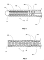
- a catheter 10 may be used in conjunction with, for example, a syringe 22 having a connector hub 24 thereon.
- the catheter 10 includes a hollow cylindrical member such as a catheter tube 20 having an intraluminal member (e.g ., a cord 26) extending therethrough and terminating at the distal end 32 of the catheter tube 20.
- the cord 20 may terminate at an enlarged end 28 ( e.g ., at a ball or spherical member) of the catheter tube 20.
- the cord 20 may terminate at the spring 30 located proximate to the distal end 32 of the catheter tube 20.
- the tube 20 may have a length from about twenty-five (25) centimeters (10 inches) to about ninety (90) centimeters (thirty-six inches). As shown in FIGs. 1 and 2 , the distal end 32 the catheter tube 20 may be substantially truncated with a flat face. The end of the cord 26 may extend from the lumen 21 of the catheter tube 20, and be free to move within the lumen 21 of the catheter tube 20.
- the cord 26 for use with catheters such as those disclosed herein may include a cable having several wound metal wires (made of, for example, stainless steel).
- the cord 26 can also be a braided line including at least three optionally braided cables.
- Such cords are strong, hypoallergenic, and flexible.
- the cord 26 may be made of a metal wire, other electrically conductive material, plastic ( e.g ., nylon), other polymers, silk, or other suitable material.
- the cord 26 may be manufactured to contain anti-thrombogenic agents or other materials, so as to prevent, for example, occlusion of the catheter during longer term use.
- other chemical agents may be introduced such as, for example, antiseptics and anesthetics.
- the connector hub 24 is shown in conjunction with the catheter tube 20.
- the catheter tube 20 is retained within connector hub 24 by interaction of bushing 35 with the proximal portion 36 of the catheter tube 20.
- the cord 26 may be trapped between the bushing 35 and the male portion of the connector hub 24.
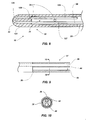
- FIG. 3 depicts an enlarged, partial cross-sectional view of the distal portion 33 of the catheter 10 shown in FIGs. 1 and 2 .
- an echogenic structure may be placed at least partially within the catheter tube 20.
- a coiled member such as a spring 30 may be placed at least partially within the catheter tube 20 proximate to the distal end 32 of the catheter tube 20.
- the exterior cross-sectional diameter of the spring 30 approximates that of the cross-sectional diameter of the lumen 21 of the catheter 10.
- the cord 26 may extend through the spring 30.
- the spring 30 may extend all the way to the end of the catheter tube 20 and may be substantially flush with the end of catheter tube 20.
- the spring 30 may be glued, heat formed or melted to the catheter tube 20.
- a plurality of apertures or holes 34 e.g ., holes about 0.4 millimeters ("mm") (or about 0.015 inches) in diameter) may be formed in the sidewall of the catheter 10 at the distal portion 33 thereof so as to enable the fluid to be transported by the catheter 10 to pass therethrough.
- the plurality of holes 34 in the distal portion 33 may enable fluid to pass from the lumen 21 of the catheter tube 20 to the holes 34 formed in the sidewall of the catheter tube 20 and from the holes 34 to the lumen 21 ( e.g ., to delivering fluids to and/or sampling fluids from a subject's body cavity or tissue).
- the spring 30 may be located in the distal portion 33 of the catheter tube 20 such that the spring 30 does not interfere with fluid passing through the lumen 21 of the catheter tube 20 and the holes 34 formed in the catheter tube 20.
- the spring may be formed from stainless steel, and the pitch of the spring may be adjusted (or the spread in the coil can be adjusted) for increased echogenicity.
- the catheter tube 20, the cord 26, and the spring 30 may be melted together.
- the length of the thus formed solid portion is chosen (e.g., from about one-half to about twice the outer diameter of the catheter tube 20) so as not to interfere with the holes 34 formed in the sidewall of the catheter tube 20 while still increasing the strength of the distal portion 33 of the catheter tube 20.
- the cord 26 may be attached ( e.g ., by adhesion, welding, molding or the like) to a portion of the spring 30.
- the cord 26 may be welded ( e.g ., tack welded) to an interior portion of the spring 30 and may interface with the spring 30 in manner similar to the attachment of the spring 38 and cord 26 shown in FIG. 4A .
- the enlarged end 28 of the cord 26 may be attached to the spring 30.
- a welding process e.g ., a tungsten inert gas welding process
- a welding process e.g ., a tungsten inert gas welding process
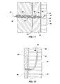
- FIG. 4A depicts an enlarged, partial cross-sectional view of the proximal portion 36 of the catheter tube 20 shown in FIGs. 1 and 2 .
- the cord 26 may be associated ( e.g ., by adhesion, welding, molding or the like) to a coiled member such as, for example, a spring 38 contained within the proximal portion 36 of the catheter tube 20 at weld 40.
- the spring 38 may be attached to the catheter tube 20 with adhesive placed along the length or around the circumference of the spring 38.
- the cord 26 may be adhered to the spring 38 by the use of an adhesive.
- the coiled member 38 defines a lumen through which fluid flows (and thus also through the lumen 21 of the tube 20) while still increasing the strength of the proximal portion 36 of the catheter tube 20.
- FIG. 4B depicts an enlarged, partial cross-sectional view of the proximal portion 36 of the catheter tube 20 in accordance with another embodiment of the invention.
- the cord 26 may be free-floating ( e.g ., not attached to the catheter tube 20) at the proximal portion 36 of the catheter tube 20.
- the cord 26 may be cut to be substantially flush (or slightly recessed) with respect to the proximal end 37 of the catheter tube 20.
- the cord 26 may be coupled to an additional structure such as, for example, the connector hub 24 ( FIG. 2 ).
- FIG. 5 depicts an enlarged, partial cross-sectional view of a distal portion 33 of the catheter tube 20 in accordance with another embodiment of the invention.
- an echogenic structure such as a spring 130 may be placed at least partially within the catheter tube 20 proximate to the distal end 32 of the catheter tube 20.
- the exterior cross-sectional diameter of the spring 130 approximates that of the cross-sectional diameter of the lumen 21 of the catheter tube 20.
- the spring 130 may be located at the distal portion 33 of the catheter tube 20 such that the spring 130 does not interfere with the fluid coupling of the lumen 21 of the catheter tube 20 with the holes 34 formed in the sidewall of the catheter tube 20.
- a portion of the spring 130 may contain a pitch (i.e ., the distance from the center of one coil to the center of an adjacent coil) that enables fluid to flow between the coils 132 of the spring 130 and exit the lumen 21 of the catheter tube 20 through the holes 34.
- the spring 130 may include a first portion 134 having a relatively small pitch and a second portion 136 having a relatively larger pitch (i.e., the second portion 136 has a pitch greater than the first portion 134).
- the first portion 134 of the spring 130 may be similar to the spring 30 or a portion thereof shown and described with reference to FIG. 3 .
- the relatively larger pitch of the second portion 136 may enable fluid communication (i.e., fluid coupling) between the lumen 21 of the catheter tube 20 and the holes 34 formed in the catheter tube 20.
- FIG. 6 depicts an enlarged view of a distal portion 33 of the catheter tube 20 in accordance with another embodiment of the invention.
- an echogenic structure such as a structure having an uneven surface 230 (e.g ., illustrated as a series of ridges similar to a coiled member) may be located within the catheter tube 20 proximate to the distal end 32 of the catheter tube 20.
- the uneven surface 230 may be formed on the inner surface of the catheter tube 20 that defines the lumen 21.
- the uneven surface 230 may be a structure formed separate from the catheter tube 20 and disposed therein proximate to the distal end 32 of the catheter tube 20.
- the uneven surface 230 may be uneven in the fact that if the inner surface of the catheter tube 20 were to be laid flat, a portion of the inner surface (e.g ., the uneven surface 230) would be non-planar.
- the uneven surface 230 may be located at the distal portion 33 of the catheter tube 20 such that the structure forming the uneven surface 230 does not interfere with fluid passing through the lumen 21 of the catheter tube 20 and the holes 34 formed in the catheter tube 20.
- openings in the structure of the uneven surface 230 proximate to the holes 34 formed in the catheter tube 20 may enable fluid communication between the lumen 21 of the catheter tube 20 and the holes 34 formed in the sidewall of the catheter tube 20.
- FIG. 7 depicts an enlarged view of the distal portion 33 of the catheter tube 20 in accordance with another embodiment of the invention.
- an echogenic structure such as a braided mesh 330 may be placed at least partially within the catheter tube 20 proximate to the distal end 32 of the catheter tube 20.
- the exterior cross-sectional diameter of the braided mesh 330 approximates that of the cross-sectional diameter of the lumen 21 of the catheter tube 20.
- the braided mesh 330 may be located at the distal portion 33 of the catheter tube 20 such that the braided mesh 330 does not interfere with fluid passing through the lumen 21 of the catheter tube 20 and the holes 34 formed in the catheter tube 20.
- the braided mesh 330 may contain openings formed therein (e.g ., openings formed between overlapping portions of the braided mesh 330) that enable fluid to flow through the braided mesh 330 and may enable fluid communication between the lumen 21 of the catheter tube 20 and the holes 34 formed in the sidewall of the catheter tube 20.
- FIG. 8 depicts an enlarged view of the distal portion 33 of the catheter tube 20 in accordance with another embodiment of the invention.
- the catheter tube 20 includes an echogenic structure such as a cord 126 (e.g ., a braided cord) extending therethrough.
- a cord 126 e.g ., a braided cord
- the cord 126 includes a first portion 127 that at least partially extends from a proximal portion of the catheter tube 20 to a distal portion 33 of the catheter tube 20.
- the cord 126 may extend from the distal portion 33 of the catheter tube 20 to a proximal portion 36 of the catheter tube 20 and may be free-floating ( e.g ., not attached to the catheter tube 20) at the proximal portion 36 of the catheter tube 20 as shown in FIG. 4B .
- the cord 126 may also be secured to the catheter 10 to provide a means for removing broken portions of the catheter 10 from the subject during use.
- the cord 126 also includes a folded-over portion 128 at the distal portion 33 of the catheter tube 33.
- the folded over portion 128 enables a second portion 129 of the cord 126 to extend from the distal portion 33 of the catheter tube 20 back toward the proximal portion of the catheter tube 20 and forms an overlapping section of the cord 126 (i.e., the second portion 129 partially overlaps the first portion 127 of the cord 126 along a lateral axis of the cord 126).
- the second portion 129 of the cord 126 may extend (in a direction toward the proximal portion of the catheter tube 20) to the most proximal hole 34 (i.e., the hole 34 being located closest to the proximal portion of the catheter tube 20).
- a portion of the folded over portion 128 of the cord 126 may be located proximate to the distal end 32 of the catheter tube 20.
- the folded over portion 128 of the cord 126 may be formed within a solid end 121 of the catheter tube 20 (i.e., the folded over portion 128 of the cord 126 is substantially surrounded by the material of the catheter tube 20).
- the folded over portion 128 of the cord 126 extends substantially to the distal end 32 of the catheter tube 20 and is covered by the catheter tube 20 at the distal end 32 thereof.
- the distal end 32 of the catheter tube 20 may be open to the lumen 21 and the cord may be otherwise secured at the distal end 32 ( e.g ., secured in the sidewall of the catheter tube 20, secured by a ball or spherical member, etc .).
- the cord 126 may form an opening between the first portion 127 and second portion 129 thereof that enables fluid communication between the lumen 21 of the catheter tube 20 and the holes 34 formed in the sidewall of the catheter tube 20.
- an echogenic structure e.g ., a spring, uneven surface, braided mesh, cord, etc.
- a clinical procedural tool e.g., a catheter
- a flexible spinal needle at the distal end thereof.
- a flexible spinal needle assembly may include a catheter such as a flexible needle.
- the flexible needle may include an echogenic structure such as those described herein within the flexible needle.
- the flexible need may include a cord (similar to the cords 26, 126 described herein) comprised of braided wires (e.g ., 16 count 0.0254 millimeter (0.001 inch) braided wires) forming an echogenic structure at a distal portion of the flexible needle.
- FIGs. 9 and 10 depict an alternative embodiment of a proximal portion 36 of a catheter tube 20.
- the proximal portion 36 of the tube is modified and strengthened by incorporation of an adhesive 44 in the first one (1) to about four (4) centimeters of the tube.
- the adhesive is formed to contain a channel 46 ( e.g ., one having a diameter of about 0.3 mm (0.012 inches)) to allow fluid flow therethrough while securing the cord 26 within the catheter tube 20.
- a catheter tube 20 is shown in use in the spinal canal of a subject (e.g ., a mammal, such as a human).
- a subject e.g ., a mammal, such as a human.
- an epidural needle 50 is inserted at a slight angle to a patient's skin until point 52 passes through ligament 54 and into the epidural space 56.
- an introducer 60 is inserted through the lumen of needle 50 until it abuts dura wall 62, which can be imaged by the ultrasound equipment. Subsequently the catheter tube 20 with stylet 70 in place is inserted through the lumen of the introducer 60.
- the stylet 70 penetrates the dura wall 62 by spreading the fibers thereof. Both the catheter tube 20 and stylet 70 are advanced into the subarachnoid space 64 under ultrasound guidance. Stylet 70 is then removed, and a syringe is used to withdraw spinal fluid.
- the proximal portion of the catheter tube 20 is maintained outside the patient's body and may be coupled to any desired tubing, syringe, etc. As can be readily seen, if any portion of the catheter tube 20 in the patient is broken, it can be retrieved by pulling on the integrated or non-integrated cord 26. Also if the catheter tube 20 should become kinked, the cord 26 will allow the flow of fluids through the catheter.
- an echogenic structure e.g ., the spring 30 located in the distal portion of the catheter tube 20 may enhance the ability of the distal portion of the catheter tube 20 to create an echo (i.e., to be echogenic and return a signal in ultrasound examinations).
- an echogenic structure e.g ., the spring 30 located in the distal portion of the catheter tube 20 may enhance the ability of the distal portion of the catheter tube 20 to create an echo (i.e., to be echogenic and return a signal in ultrasound examinations).
- the distal portion of the catheter tube 20 may be relatively more easily identified and located during a procedure utilizing ultrasonic guidance to place a catheter within a subject.
- Electrical epidural stimulation of the distal tip can be used to confirm epidural catheter placement in the epidural space in both adult and pediatric patients. Motor responses from electrical stimulation are interpreted particularly in the event of misplacing an epidural catheter (for instance, subarachnoid, subdural, or intravascular). For instance bipolar electrical stimulation can be used in such an embodiment.
- a specialized catheter can provide many other functions, including monitoring of spinal cord potentials, measurement of epidural pressure, and spinal cord stimulation.
- the invention may also be used for, e.g ., intrathecal administration of medicines to a subject.
- a catheter tube may be made of flexible pre-tapered, pre-holed TECOTHANE® 55D polyurethane tubing 0.9 mm (0.035 inch) outer diameter, 0.6 mm (0.025 inch) inner diameter) or nylon ( e.g ., PEBAX® 55D).
- TECOTHANE® 55D polyurethane tubing 0.9 mm (0.035 inch) outer diameter, 0.6 mm (0.025 inch) inner diameter
- nylon e.g ., PEBAX® 55D
- it can be made of a synthetic absorbable polymer in a manner similar to that disclosed in U.S. Patent 5,129,889 to Hahn et al. (Jul. 14, 1992 ), the contents of which are incorporated herein by this reference.
- the cord may be, for example, twisted 0.009 1 X 2 stainless or 0.25 mm (0.010 inch) diameter nylon.
- the enlarged portion can thus have a diameter of 0.86 mm (0.035 inches).
- the coiled member may be made of 304 stainless springs (0.6 mm (0.024 inch) outer diameter, 0.4 mm (0.016 inch) inner diameter).
- the braided mesh and structure including the uneven surface may be made from a metal (e.g., 304 stainless steel), a polymer ( e.g ., nylon), etc.
- the adhesive may be UV cured flexible adhesive (type AAS 2465 LV).
- a process for producing the improved catheter can include obtaining a tube of appropriate length, placing and securing an echogenic structure (e.g ., a spring) within a distal portion of the tube, and cutting through a distal end of the tube (e.g ., with a razor under sterile conditions) so that a portion of the spring is substantially flush with the distal end of the tube.
- an echogenic structure e.g ., a spring
- the invention includes a method of forming a tool for a clinical procedure performed upon a subject utilizing ultrasound guidance, the method comprising: forming a catheter having a lumen formed therein; disposing an echogenic structure within the lumen of the catheter; and locating a portion of the echogenic structure at a distal end of the catheter to improve the echogenicity of the distal end of the catheter.
- an echogenic structure may be disposed within the lumen of the catheter comprising disposing a spring within the lumen of the catheter and locating a portion of the spring flush with the distal end of the catheter.
- Such an embodiment can further comprise forming a portion of the spring to exhibit a pitch that enables fluid to flow between at least two coils of the spring.
- an echogenic structure may be disposed within the lumen of the catheter comprises disposing a braided mesh within the lumen of the catheter.
- an echogenic structure may be disposed within the lumen of the catheter further comprises forming an uneven surface within the lumen of the catheter.
- an echogenic structure may be disposed within the lumen of the catheter further comprising: disposing a cord within the lumen of the catheter; and folding the cord such that a first portion of the cord extends from a proximal portion of the catheter to a distal portion of the catheter and a second portion of the cord extends from the distal portion of the catheter toward the proximal portion of the catheter.
- the cord may be secured to the distal end of the catheter to provide a means for removing broken portions of the catheter from the subject during use.
- the invention also includes a method for ultrasound guidance of a tool for a clinical procedure performed upon a subject, wherein the improvement comprises: utilizing, as the tool, a catheter having an echogenic structure at a distal portion thereof for improved echogenicity, together with means for removing broken portions of the catheter from the subject during use.
- a catheter having an echogenic structure at a distal portion thereof for improved echogenicity together with means for removing broken portions of the catheter from the subject during use.
- Such an embodiment may, further comprise forming the echogenic structure and the means for removing broken portions of the catheter from a single cord.
- Such an embodiment may further comprise overlapping a portion of the cord at a distal end of the catheter to form the echogenic structure.
- Such embodiments may further comprise forming the echogenic structure from a spring; and extending a portion of the spring to a distal end of the catheter.
- the means for removing broken portions of the catheter may comprise extending a cord through the catheter and terminating the cord at the distal end of the catheter with a ball or spherical member.
- Such an embodiment may further comprise abutting a portion of the spring, when the catheter is being withdrawn from the subject, with the ball or spherical member.
- Such embodiments may further comprise forming the cord to increase echogenicity thereof.
- Such embodiments may further comprise increasing echogenicity of the distal end of the catheter for improved imaging by an ultrasound sensor used to guide placement of the catheter with the spring and the ball or spherical member.
- the invention also includes a catheter for delivering fluids to and/or sampling fluids from a body cavity or tissue of a subject with the aid of ultrasound guidance, the catheter comprising: a catheter tube having a lumen formed therein, the catheter tube having a plurality of apertures formed in a sidewall of the catheter tube at a distal portion thereof; and an echogenic structure at least partially disposed within the distal portion of the catheter tube, the echogenic structure extending along at least one aperture of the plurality of apertures formed in a sidewall of the catheter tube and increasing echogenicity of the distal portion of the catheter for improved imaging by an ultrasound sensor used to guide placement of the catheter.
- the echogenic structure may form at least one opening therein, the at least one opening enabling the lumen formed in the catheter tube to be in fluid communication with at least one aperture of the plurality of apertures formed in a sidewall of the catheter tube.
- the echogenic structure may comprise a spring including a plurality of coils, at least two coils of the plurality of coils having a pitch that forms the at least one opening in the echogenic structure.
- the spring may comprise a first portion having a first pitch and a second portion having a second pitch, wherein the first pitch is less than the second pitch and wherein a portion the second pitch forms the at least one opening in the echogenic structure.
- the echogenic structure may comprise a braided mesh, wherein overlapping portions of the braided mesh form the at least one opening in the echogenic structure.
- the invention further includes a catheter for delivering fluids to and/or sampling fluids from a body cavity or tissue of a subject with the aid of ultrasound guidance, the catheter comprising: a catheter tube having a proximal end and a distal end, wherein the distal end is a truncated flat faced portion of the catheter tube; and an echogenic structure at least partially disposed within a distal portion of the catheter tube and a portion of the echogenic structure being substantially flush with the distal end of the catheter tube, the echogenic structure increasing echogenicity of the distal portion of the catheter for improved imaging by an ultrasound sensor used to guide placement of the catheter.
- the echogenic structure may comprise a spring.
- the spring may comprise a first portion having a first pitch and a second portion having a second pitch, the second pitch being greater than the first pitch, and wherein the second pitch enables fluid within the catheter tube to be in fluid communication with at least one aperture formed in a sidewall of the catheter tube.
- the echogenic structure may comprise a braided mesh.
- the echogenic structure may comprise a cord, the cord comprising: a first portion extending from a proximal portion of the catheter tube to a distal portion of the catheter tube; and a second portion extending from the distal portion of the catheter tube toward the proximal portion of the catheter tube, the first portion and the second portion being connected at a folded-over portion, a portion of the folded-over portion being disposed substantially flush with the distal end of the catheter tube.
- the invention further includes a catheter for delivering fluids to and/or sampling fluids from a body cavity or tissue of a subject with the aid of ultrasound guidance, the catheter comprising: a catheter tube having a lumen formed therein; and a cord at least partially disposed in the lumen of the catheter tube, the cord comprising: a first portion extending from a proximal portion of the catheter tube to a distal portion of the catheter tube; and a second portion extending from the distal portion of the catheter tube toward the proximal portion of the catheter tube, the first portion and the second portion being connected at a folded over portion.
- the folded over portion may extend substantially to the distal end of the catheter tube and where the folded over portion is substantially surrounded by the catheter tube to form a solid end portion.
- the invention further includes a catheter for delivering fluids to and/or sampling fluids from a body cavity or tissue of a subject with the aid of ultrasound guidance, the catheter comprising: a tube having a proximal end and a distal end, wherein the distal end is a truncated flat faced portion of the tube; a spring positioned within a distal portion of the tube, and extending all of the way to the distal end of the tube, for improved echogenicity; and a cord extending through the tube and terminating in a ball or spherical member useful for removing broken portions thereof from the subject; wherein, upon withdrawal of the catheter from the subject during use, the ball or spherical member abuts the spring and the distal end of the catheter, and further wherein the ball or spherical member, together with the spring, increases echogenicity of the distal portion of the catheter for improved imaging by an ultrasound sensor used to guide placement of the catheter.
- the invention also includes a process for producing such a catheter, the process comprising: obtaining a tube of appropriate length; placing and securing the spring within the distal portion of the tube; and cutting through the distal portion of the tube so that a portion of the spring is substantially flush with the distal end of the tube.
Applications Claiming Priority (1)
| Application Number | Priority Date | Filing Date | Title |
|---|---|---|---|
| US33577110P | 2010-01-12 | 2010-01-12 |
Publications (1)
| Publication Number | Publication Date |
|---|---|
| EP2343098A1 true EP2343098A1 (fr) | 2011-07-13 |
Family
ID=43640162
Family Applications (1)
| Application Number | Title | Priority Date | Filing Date |
|---|---|---|---|
| EP11150487A Withdrawn EP2343098A1 (fr) | 2010-01-12 | 2011-01-10 | Cathéter échogénique guidé par ultrasons et procédés correspondants |
Country Status (5)
| Country | Link |
|---|---|
| US (1) | US20110172542A1 (fr) |
| EP (1) | EP2343098A1 (fr) |
| JP (1) | JP5775689B2 (fr) |
| KR (1) | KR101333840B1 (fr) |
| CA (1) | CA2726418A1 (fr) |
Cited By (4)
| Publication number | Priority date | Publication date | Assignee | Title |
|---|---|---|---|---|
| EP2814554A4 (fr) * | 2012-02-16 | 2016-03-16 | Custom Med Applications Inc | Cathéters, cathéters à utiliser dans des opérations chirurgicales guidées par ultrasons et procédés associés |
| WO2016204759A1 (fr) * | 2015-06-18 | 2016-12-22 | Avent, Inc. | Élément de bobine échogène pour un ensemble de cathéter |
| US10773055B2 (en) | 2015-06-18 | 2020-09-15 | Avent, Inc. | Echogenic catheter member |
| US11779306B2 (en) | 2015-07-21 | 2023-10-10 | Avent, Inc. | Ultrasonic catheter assembly |
Families Citing this family (11)
| Publication number | Priority date | Publication date | Assignee | Title |
|---|---|---|---|---|
| US9254146B2 (en) | 2010-10-18 | 2016-02-09 | Avent, Inc. | Echogenic nerve block apparatus and system |
| AU2014207334B2 (en) * | 2013-01-18 | 2016-09-08 | Chunyuan Qiu | Anchoring nerve block catheter |
| EP2961462A4 (fr) | 2013-02-27 | 2017-01-18 | The George Washington University | Système de pose de cathéter assisté par ultrasons |
| EP2964100B1 (fr) * | 2013-03-06 | 2018-06-20 | Muffin Incorporated | Pointe de fil-guide échotransparente |
| US10265504B2 (en) | 2013-03-15 | 2019-04-23 | Custom Medical Application | Safety neural injection system and related methods |
| US20150238730A1 (en) * | 2014-02-27 | 2015-08-27 | The George Washington University | Ultrasound visible catheter |
| US10143826B2 (en) | 2014-10-31 | 2018-12-04 | SonoStik LLC | Wire introduction device for introducing guide wire |
| CN106621005B (zh) * | 2016-12-27 | 2019-03-22 | 珠海金导医疗科技有限公司 | 一种柔性加强型硬膜外麻醉导管的制造方法 |
| US11872356B2 (en) | 2018-01-05 | 2024-01-16 | Becton, Dickinson And Company | Echogenic catheter and catheter system |
| CN109646053B (zh) * | 2018-12-27 | 2022-03-25 | 深圳北芯生命科技股份有限公司 | 血管内超声导管 |
| CA3146937A1 (fr) * | 2019-08-14 | 2021-02-18 | Baylis Medical Company Inc. | Gaine medicale et systemes et procedes d'utilisation de gaine medicale |
Citations (21)
| Publication number | Priority date | Publication date | Assignee | Title |
|---|---|---|---|---|
| US3856009A (en) | 1971-11-26 | 1974-12-24 | Johnson & Johnson | Catheter placement unit |
| US4518383A (en) | 1982-08-06 | 1985-05-21 | Evans John M | Instrument and method for epidural and spinal anaesthesia |
| US4650472A (en) | 1985-08-30 | 1987-03-17 | Cook, Incorporated | Apparatus and method for effecting percutaneous catheterization of a blood vessel using a small gauge introducer needle |
| US5084022A (en) | 1989-10-04 | 1992-01-28 | Lake Region Manufacturing Company, Inc. | Graduated guidewire |
| US5106376A (en) | 1989-07-07 | 1992-04-21 | B. Braun Melsungen Ag | Anaesthesia set |
| US5129889A (en) | 1987-11-03 | 1992-07-14 | Hahn John L | Synthetic absorbable epidural catheter |
| WO1992011889A1 (fr) * | 1990-12-27 | 1992-07-23 | Wormer Mark E Van | Catheter a caracteristiques acoustiques ameliorees |
| US5213578A (en) | 1991-08-28 | 1993-05-25 | Vygon Gmbh & Co. Kg | Anesthesia set |
| US5232442A (en) | 1989-12-11 | 1993-08-03 | Brigham And Women's Hospital | Method and apparatus for inducing anesthesia |
| FR2715312A1 (fr) * | 1994-01-27 | 1995-07-28 | Robert Jean Luc | Cathéter échovisible pour le traitement sclérosant des varices. |
| US5490845A (en) | 1994-09-20 | 1996-02-13 | Racz; Gabor J. | R-X safety catheter |
| US5490521A (en) | 1993-08-31 | 1996-02-13 | Medtronic, Inc. | Ultrasound biopsy needle |
| EP0810003A2 (fr) * | 1996-05-30 | 1997-12-03 | Target Therapeutics, Inc. | Cathéter tressé résistant au tortillement à trous latérales distales |
| US5899891A (en) | 1996-09-05 | 1999-05-04 | Epimed International, Inc. | Catheter |
| WO1999051294A1 (fr) * | 1998-04-08 | 1999-10-14 | Medtronic, Inc. | Catheter a capacite de production d'echos renforcee |
| US6019724A (en) | 1995-02-22 | 2000-02-01 | Gronningsaeter; Aage | Method for ultrasound guidance during clinical procedures |
| US20030109823A1 (en) * | 2001-12-12 | 2003-06-12 | Medtronic, Inc. | Guide catheter |
| WO2004020024A1 (fr) * | 2002-08-30 | 2004-03-11 | Inrad, Inc. | Aiguille de localisation comprenant une distribution de fluide |
| WO2007056302A2 (fr) * | 2005-11-08 | 2007-05-18 | Custom Medical Applications, Inc. | Catheter renforce avec une pointe distale articulee |
| US20080065017A1 (en) | 2003-10-27 | 2008-03-13 | Racz N Sandor | Method of using flexible spinal needle assemblies |
| WO2008052764A2 (fr) * | 2006-11-03 | 2008-05-08 | Smiths Medical Deutschland Gmbh | Cathéter |
Family Cites Families (34)
| Publication number | Priority date | Publication date | Assignee | Title |
|---|---|---|---|---|
| US3885561A (en) * | 1971-12-15 | 1975-05-27 | Charles N Mazal Cami | Catheter |
| US4194513A (en) * | 1977-05-05 | 1980-03-25 | Indiana University Foundation | Antenatal cell extracting device and method |
| US4516972A (en) * | 1982-01-28 | 1985-05-14 | Advanced Cardiovascular Systems, Inc. | Guiding catheter and method of manufacture |
| US4863424A (en) * | 1983-11-18 | 1989-09-05 | Blake Joseph W Iii | Tubular medical device and method of making and using the same |
| US4596553A (en) * | 1984-05-07 | 1986-06-24 | Hans Lee | Method and apparatus for performing suction lipectomy |
| US5181509A (en) * | 1984-11-21 | 1993-01-26 | Spofford Bryan T | Transtracheal catheter system |
| US4610671A (en) * | 1985-03-28 | 1986-09-09 | Luther Medical Products, Inc. | Assembly of stylet and catheter |
| US4721117A (en) * | 1986-04-25 | 1988-01-26 | Advanced Cardiovascular Systems, Inc. | Torsionally stabilized guide wire with outer jacket |
| US4904431A (en) * | 1988-08-12 | 1990-02-27 | Baxter International, Inc. | Process for manufacturing catheters |
| US5176661A (en) * | 1988-09-06 | 1993-01-05 | Advanced Cardiovascular Systems, Inc. | Composite vascular catheter |
| US4955862A (en) * | 1989-05-22 | 1990-09-11 | Target Therapeutics, Inc. | Catheter and catheter/guide wire device |
| US5114401A (en) * | 1990-02-23 | 1992-05-19 | New England Deaconess Hospital Corporation | Method for central venous catheterization |
| US5190520A (en) * | 1990-10-10 | 1993-03-02 | Strato Medical Corporation | Reinforced multiple lumen catheter |
| US5178158A (en) * | 1990-10-29 | 1993-01-12 | Boston Scientific Corporation | Convertible guidewire-catheter with soft tip |
| US5106369A (en) * | 1990-11-28 | 1992-04-21 | Board Of Regents, The University Of Texas System | Percutaneous umbilical cord stabilizer |
| US5308342A (en) * | 1991-08-07 | 1994-05-03 | Target Therapeutics, Inc. | Variable stiffness catheter |
| US5263947A (en) * | 1991-08-20 | 1993-11-23 | Bioderm, Inc. | External incontinence device |
| US5290230A (en) * | 1992-05-11 | 1994-03-01 | Advanced Cardiovascular Systems, Inc. | Intraluminal catheter with a composite shaft |
| JPH06190052A (ja) * | 1992-09-18 | 1994-07-12 | Cordis Corp | 繊維強化したカテーテル挿入器 |
| US5356388A (en) * | 1992-09-22 | 1994-10-18 | Target Therapeutics, Inc. | Perfusion catheter system |
| US5531690A (en) * | 1992-10-30 | 1996-07-02 | Cordis Corporation | Rapid exchange catheter |
| US5348541A (en) * | 1993-05-05 | 1994-09-20 | Lyell Mark S | Suprapubic catheter placement apparatus (lyell sound) |
| US5382238A (en) * | 1993-05-20 | 1995-01-17 | Quinton Instrument Company | Catheter stiffeners |
| US5545138A (en) * | 1994-02-28 | 1996-08-13 | Medtronic, Inc. | Adjustable stiffness dilatation catheter |
| US5746692A (en) * | 1994-05-05 | 1998-05-05 | Imagen Medical, Inc. | Catheter and endoscope system with distal protruding ball tip and method |
| JP3651031B2 (ja) * | 1994-11-04 | 2005-05-25 | 株式会社日立メディコ | Ivr用カテーテル |
| JP3318921B2 (ja) * | 1995-02-21 | 2002-08-26 | ニプロ株式会社 | スタイレットおよびスタイレット用コネクター |
| EP0902651B1 (fr) * | 1996-05-14 | 2002-07-17 | PFM Produkte für die Medizin Aktiengesellschaft | Implant renforce pour conduits du corps |
| US6394956B1 (en) * | 2000-02-29 | 2002-05-28 | Scimed Life Systems, Inc. | RF ablation and ultrasound catheter for crossing chronic total occlusions |
| US7014610B2 (en) * | 2001-02-09 | 2006-03-21 | Medtronic, Inc. | Echogenic devices and methods of making and using such devices |
| CA2524651A1 (fr) * | 2003-05-15 | 2004-12-02 | Applied Medical Resources Corporation | Stent echogenique |
| US8382674B2 (en) * | 2005-12-02 | 2013-02-26 | Abbott Cardiovascular Systems Inc. | Visualization of a catheter viewed under ultrasound imaging |
| CA2645930A1 (fr) * | 2006-03-17 | 2007-09-27 | Crossbeta Biosciences B.V. | Procedes de liaison de structures beta croisees avec des molecules chaperonnes |
| US20080097218A1 (en) * | 2006-08-24 | 2008-04-24 | Boston Scientific Scimed, Inc. | Blood vessel puncture locating apparatus and method |
-
2010
- 2010-12-23 CA CA2726418A patent/CA2726418A1/fr not_active Abandoned
- 2010-12-27 JP JP2010289163A patent/JP5775689B2/ja not_active Expired - Fee Related
-
2011
- 2011-01-10 EP EP11150487A patent/EP2343098A1/fr not_active Withdrawn
- 2011-01-10 US US12/930,580 patent/US20110172542A1/en not_active Abandoned
- 2011-01-11 KR KR1020110002681A patent/KR101333840B1/ko active IP Right Grant
Patent Citations (21)
| Publication number | Priority date | Publication date | Assignee | Title |
|---|---|---|---|---|
| US3856009A (en) | 1971-11-26 | 1974-12-24 | Johnson & Johnson | Catheter placement unit |
| US4518383A (en) | 1982-08-06 | 1985-05-21 | Evans John M | Instrument and method for epidural and spinal anaesthesia |
| US4650472A (en) | 1985-08-30 | 1987-03-17 | Cook, Incorporated | Apparatus and method for effecting percutaneous catheterization of a blood vessel using a small gauge introducer needle |
| US5129889A (en) | 1987-11-03 | 1992-07-14 | Hahn John L | Synthetic absorbable epidural catheter |
| US5106376A (en) | 1989-07-07 | 1992-04-21 | B. Braun Melsungen Ag | Anaesthesia set |
| US5084022A (en) | 1989-10-04 | 1992-01-28 | Lake Region Manufacturing Company, Inc. | Graduated guidewire |
| US5232442A (en) | 1989-12-11 | 1993-08-03 | Brigham And Women's Hospital | Method and apparatus for inducing anesthesia |
| WO1992011889A1 (fr) * | 1990-12-27 | 1992-07-23 | Wormer Mark E Van | Catheter a caracteristiques acoustiques ameliorees |
| US5213578A (en) | 1991-08-28 | 1993-05-25 | Vygon Gmbh & Co. Kg | Anesthesia set |
| US5490521A (en) | 1993-08-31 | 1996-02-13 | Medtronic, Inc. | Ultrasound biopsy needle |
| FR2715312A1 (fr) * | 1994-01-27 | 1995-07-28 | Robert Jean Luc | Cathéter échovisible pour le traitement sclérosant des varices. |
| US5490845A (en) | 1994-09-20 | 1996-02-13 | Racz; Gabor J. | R-X safety catheter |
| US6019724A (en) | 1995-02-22 | 2000-02-01 | Gronningsaeter; Aage | Method for ultrasound guidance during clinical procedures |
| EP0810003A2 (fr) * | 1996-05-30 | 1997-12-03 | Target Therapeutics, Inc. | Cathéter tressé résistant au tortillement à trous latérales distales |
| US5899891A (en) | 1996-09-05 | 1999-05-04 | Epimed International, Inc. | Catheter |
| WO1999051294A1 (fr) * | 1998-04-08 | 1999-10-14 | Medtronic, Inc. | Catheter a capacite de production d'echos renforcee |
| US20030109823A1 (en) * | 2001-12-12 | 2003-06-12 | Medtronic, Inc. | Guide catheter |
| WO2004020024A1 (fr) * | 2002-08-30 | 2004-03-11 | Inrad, Inc. | Aiguille de localisation comprenant une distribution de fluide |
| US20080065017A1 (en) | 2003-10-27 | 2008-03-13 | Racz N Sandor | Method of using flexible spinal needle assemblies |
| WO2007056302A2 (fr) * | 2005-11-08 | 2007-05-18 | Custom Medical Applications, Inc. | Catheter renforce avec une pointe distale articulee |
| WO2008052764A2 (fr) * | 2006-11-03 | 2008-05-08 | Smiths Medical Deutschland Gmbh | Cathéter |
Non-Patent Citations (1)
| Title |
|---|
| TUI; BHARGAVA: "Atlas of Ultrasound and Nerve Stimulation-Guided Regional Anesthesia", 2007, pages: 16.1 |
Cited By (5)
| Publication number | Priority date | Publication date | Assignee | Title |
|---|---|---|---|---|
| EP2814554A4 (fr) * | 2012-02-16 | 2016-03-16 | Custom Med Applications Inc | Cathéters, cathéters à utiliser dans des opérations chirurgicales guidées par ultrasons et procédés associés |
| WO2016204759A1 (fr) * | 2015-06-18 | 2016-12-22 | Avent, Inc. | Élément de bobine échogène pour un ensemble de cathéter |
| US10675441B2 (en) | 2015-06-18 | 2020-06-09 | Avent, Inc. | Echogenic coil member for a catheter assembly |
| US10773055B2 (en) | 2015-06-18 | 2020-09-15 | Avent, Inc. | Echogenic catheter member |
| US11779306B2 (en) | 2015-07-21 | 2023-10-10 | Avent, Inc. | Ultrasonic catheter assembly |
Also Published As
| Publication number | Publication date |
|---|---|
| US20110172542A1 (en) | 2011-07-14 |
| CA2726418A1 (fr) | 2011-07-12 |
| KR101333840B1 (ko) | 2013-11-27 |
| JP5775689B2 (ja) | 2015-09-09 |
| JP2011143245A (ja) | 2011-07-28 |
| KR20110083528A (ko) | 2011-07-20 |
Similar Documents
| Publication | Publication Date | Title |
|---|---|---|
| EP2343098A1 (fr) | Cathéter échogénique guidé par ultrasons et procédés correspondants | |
| EP2089088B1 (fr) | Sondes de perfusion | |
| CA2500157C (fr) | Catheter pour anesthesie pour produire un stimulus electrique | |
| US5899891A (en) | Catheter | |
| RU2604395C2 (ru) | Эхогенное устройство и система для блокады нерва | |
| JP5662159B2 (ja) | 可撓性脊椎針とともに使用するためのフロー要素、針組立体、ならびにこれらの製造方法および使用方法 | |
| US20080275466A1 (en) | Dual cannula system and method for using same | |
| US20090187140A1 (en) | Flow elements for use with flexible spinal needles, needle assemblies and methods therefor | |
| CA2527193A1 (fr) | Ensemble catheter intracranien pour traitement precis de tissu cerebral | |
| US20050245944A1 (en) | Apparatus for facilitating delivery of at least one device to a target site in a body | |
| JP5775584B2 (ja) | ガイドワイヤが備えられたカテーテルセット | |
| WO2020190623A1 (fr) | Cathéter avec couche d'étanchéité | |
| US20110270090A1 (en) | Needle having ultrasound opaque elements | |
| US20150011873A1 (en) | Catheters, catheters for use in ultrasound guided procedures, and related methods | |
| WO2015081967A1 (fr) | Cathéter échogène à demeure | |
| WO2009023536A1 (fr) | Système de guidage de cathéter |
Legal Events
| Date | Code | Title | Description |
|---|---|---|---|
| PUAI | Public reference made under article 153(3) epc to a published international application that has entered the european phase |
Free format text: ORIGINAL CODE: 0009012 |
|
| AK | Designated contracting states |
Kind code of ref document: A1 Designated state(s): AL AT BE BG CH CY CZ DE DK EE ES FI FR GB GR HR HU IE IS IT LI LT LU LV MC MK MT NL NO PL PT RO RS SE SI SK SM TR |
|
| AX | Request for extension of the european patent |
Extension state: BA ME |
|
| 17P | Request for examination filed |
Effective date: 20120113 |
|
| REG | Reference to a national code |
Ref country code: HK Ref legal event code: DE Ref document number: 1160041 Country of ref document: HK |
|
| 17Q | First examination report despatched |
Effective date: 20131115 |
|
| STAA | Information on the status of an ep patent application or granted ep patent |
Free format text: STATUS: THE APPLICATION IS DEEMED TO BE WITHDRAWN |
|
| 18D | Application deemed to be withdrawn |
Effective date: 20140326 |
|
| REG | Reference to a national code |
Ref country code: HK Ref legal event code: WD Ref document number: 1160041 Country of ref document: HK |