EP2342539B1 - Absolute position measuring device - Google Patents
Absolute position measuring device Download PDFInfo
- Publication number
- EP2342539B1 EP2342539B1 EP09778775.8A EP09778775A EP2342539B1 EP 2342539 B1 EP2342539 B1 EP 2342539B1 EP 09778775 A EP09778775 A EP 09778775A EP 2342539 B1 EP2342539 B1 EP 2342539B1
- Authority
- EP
- European Patent Office
- Prior art keywords
- code
- track
- scanning
- sequence
- absolute position
- Prior art date
- Legal status (The legal status is an assumption and is not a legal conclusion. Google has not performed a legal analysis and makes no representation as to the accuracy of the status listed.)
- Active
Links
- 238000011156 evaluation Methods 0.000 claims description 9
- 238000005259 measurement Methods 0.000 description 7
- 238000010586 diagram Methods 0.000 description 4
- 238000004364 calculation method Methods 0.000 description 3
- 230000001419 dependent effect Effects 0.000 description 3
- 230000003287 optical effect Effects 0.000 description 3
- 230000015654 memory Effects 0.000 description 2
- 238000005070 sampling Methods 0.000 description 2
- 125000004122 cyclic group Chemical group 0.000 description 1
- 238000001514 detection method Methods 0.000 description 1
- 230000001939 inductive effect Effects 0.000 description 1
- 238000004519 manufacturing process Methods 0.000 description 1
Images


Classifications
-
- G—PHYSICS
- G01—MEASURING; TESTING
- G01D—MEASURING NOT SPECIALLY ADAPTED FOR A SPECIFIC VARIABLE; ARRANGEMENTS FOR MEASURING TWO OR MORE VARIABLES NOT COVERED IN A SINGLE OTHER SUBCLASS; TARIFF METERING APPARATUS; MEASURING OR TESTING NOT OTHERWISE PROVIDED FOR
- G01D5/00—Mechanical means for transferring the output of a sensing member; Means for converting the output of a sensing member to another variable where the form or nature of the sensing member does not constrain the means for converting; Transducers not specially adapted for a specific variable
- G01D5/12—Mechanical means for transferring the output of a sensing member; Means for converting the output of a sensing member to another variable where the form or nature of the sensing member does not constrain the means for converting; Transducers not specially adapted for a specific variable using electric or magnetic means
- G01D5/244—Mechanical means for transferring the output of a sensing member; Means for converting the output of a sensing member to another variable where the form or nature of the sensing member does not constrain the means for converting; Transducers not specially adapted for a specific variable using electric or magnetic means influencing characteristics of pulses or pulse trains; generating pulses or pulse trains
- G01D5/249—Mechanical means for transferring the output of a sensing member; Means for converting the output of a sensing member to another variable where the form or nature of the sensing member does not constrain the means for converting; Transducers not specially adapted for a specific variable using electric or magnetic means influencing characteristics of pulses or pulse trains; generating pulses or pulse trains using pulse code
- G01D5/2497—Absolute encoders
-
- G—PHYSICS
- G01—MEASURING; TESTING
- G01D—MEASURING NOT SPECIALLY ADAPTED FOR A SPECIFIC VARIABLE; ARRANGEMENTS FOR MEASURING TWO OR MORE VARIABLES NOT COVERED IN A SINGLE OTHER SUBCLASS; TARIFF METERING APPARATUS; MEASURING OR TESTING NOT OTHERWISE PROVIDED FOR
- G01D5/00—Mechanical means for transferring the output of a sensing member; Means for converting the output of a sensing member to another variable where the form or nature of the sensing member does not constrain the means for converting; Transducers not specially adapted for a specific variable
- G01D5/12—Mechanical means for transferring the output of a sensing member; Means for converting the output of a sensing member to another variable where the form or nature of the sensing member does not constrain the means for converting; Transducers not specially adapted for a specific variable using electric or magnetic means
- G01D5/244—Mechanical means for transferring the output of a sensing member; Means for converting the output of a sensing member to another variable where the form or nature of the sensing member does not constrain the means for converting; Transducers not specially adapted for a specific variable using electric or magnetic means influencing characteristics of pulses or pulse trains; generating pulses or pulse trains
- G01D5/245—Mechanical means for transferring the output of a sensing member; Means for converting the output of a sensing member to another variable where the form or nature of the sensing member does not constrain the means for converting; Transducers not specially adapted for a specific variable using electric or magnetic means influencing characteristics of pulses or pulse trains; generating pulses or pulse trains using a variable number of pulses in a train
- G01D5/2454—Encoders incorporating incremental and absolute signals
-
- G—PHYSICS
- G01—MEASURING; TESTING
- G01D—MEASURING NOT SPECIALLY ADAPTED FOR A SPECIFIC VARIABLE; ARRANGEMENTS FOR MEASURING TWO OR MORE VARIABLES NOT COVERED IN A SINGLE OTHER SUBCLASS; TARIFF METERING APPARATUS; MEASURING OR TESTING NOT OTHERWISE PROVIDED FOR
- G01D5/00—Mechanical means for transferring the output of a sensing member; Means for converting the output of a sensing member to another variable where the form or nature of the sensing member does not constrain the means for converting; Transducers not specially adapted for a specific variable
- G01D5/26—Mechanical means for transferring the output of a sensing member; Means for converting the output of a sensing member to another variable where the form or nature of the sensing member does not constrain the means for converting; Transducers not specially adapted for a specific variable characterised by optical transfer means, i.e. using infrared, visible, or ultraviolet light
- G01D5/32—Mechanical means for transferring the output of a sensing member; Means for converting the output of a sensing member to another variable where the form or nature of the sensing member does not constrain the means for converting; Transducers not specially adapted for a specific variable characterised by optical transfer means, i.e. using infrared, visible, or ultraviolet light with attenuation or whole or partial obturation of beams of light
- G01D5/34—Mechanical means for transferring the output of a sensing member; Means for converting the output of a sensing member to another variable where the form or nature of the sensing member does not constrain the means for converting; Transducers not specially adapted for a specific variable characterised by optical transfer means, i.e. using infrared, visible, or ultraviolet light with attenuation or whole or partial obturation of beams of light the beams of light being detected by photocells
- G01D5/347—Mechanical means for transferring the output of a sensing member; Means for converting the output of a sensing member to another variable where the form or nature of the sensing member does not constrain the means for converting; Transducers not specially adapted for a specific variable characterised by optical transfer means, i.e. using infrared, visible, or ultraviolet light with attenuation or whole or partial obturation of beams of light the beams of light being detected by photocells using displacement encoding scales
- G01D5/34776—Absolute encoders with analogue or digital scales
- G01D5/34792—Absolute encoders with analogue or digital scales with only digital scales or both digital and incremental scales
-
- H—ELECTRICITY
- H03—ELECTRONIC CIRCUITRY
- H03M—CODING; DECODING; CODE CONVERSION IN GENERAL
- H03M1/00—Analogue/digital conversion; Digital/analogue conversion
- H03M1/12—Analogue/digital converters
- H03M1/22—Analogue/digital converters pattern-reading type
- H03M1/24—Analogue/digital converters pattern-reading type using relatively movable reader and disc or strip
- H03M1/28—Analogue/digital converters pattern-reading type using relatively movable reader and disc or strip with non-weighted coding
- H03M1/287—Analogue/digital converters pattern-reading type using relatively movable reader and disc or strip with non-weighted coding using gradually changing slit width or pitch within one track; using plural tracks having slightly different pitches, e.g. of the Vernier or nonius type
Definitions
- the invention relates to an absolute position coding of a position measuring device according to the patent claim 1.
- the invention relates to an absolute position measuring device according to claim 6.
- Absolute position measuring devices are increasingly used to determine the position of two relatively moving bodies.
- Absolute position measuring devices have the advantage over purely incremental measuring systems that correct position information can be output immediately in every relative position even after interruption of the supply energy.
- the absolute position is represented by a position coding.
- Particularly space-saving is the arrangement of the position coding or position information in a single code track with successively arranged in the measuring direction code elements.
- the code elements are arranged in pseudo-random distribution one behind the other, so that a certain number of successive code elements each forms a code word that uniquely defines the absolute position.
- serial or sequential code is also often called chain code or pseudo-random code.
- a decoding table is used in which each codeword is assigned a position.
- the codeword forms the address for the decoding table, so that the output for that codeword absolute position is pending and available for further processing.
- the WO 2008/056546 A1 shows a measure of how a position coding and a length measuring device can be designed to be able to code large measuring ranges and to reduce the effort of decoding.
- two mutually parallel code tracks are provided.
- a first code sequence is arranged several times in the measuring direction one behind the other.
- this same code sequence is also arranged several times in the measuring direction one behind the other.
- the width of the code elements of the first track differs slightly from the width of the code elements of the second track, so that the extent in the measuring direction of the code sequence in the first track differs slightly from the extent of the code sequence in the second track.
- This difference which changes over the measuring range, is used to distinguish between the successive identical code sequences of the first track, that is to say to code them.
- the absolute position is unique by the combination of partial positions within the respective code sequences of the two tracks at each position within the measuring range.
- a similar position coding is off EP 0800725 B1 known.
- a disadvantage of this position coding is that the unambiguous assignment of the partial positions determined in the two tracks is relatively complicated due to the different widths of the code elements of the two tracks. Furthermore, differently shaped detector units are required due to the different widths of the code elements.
- the object of the invention is to provide a simple absolute position coding for a position measuring device, with the large measuring ranges can be absolutely coded.
- This position coding has mutually parallel and extending in the measuring direction code tracks, wherein a code track having a first code sequence consisting of a plurality of code elements, the other code track has a second code sequence which consists of a plurality of code elements in multiple succession, the code sequences of one code track and the other code track have different lengths, and the code elements of a code track and the other code track each have the same dimensions in the measuring direction.
- Different lengths here mean that the length of one code sequence differs from the length of the other code sequence, that is to say that one code sequence has a number of code elements which deviate from the number of code elements of the other code sequence.
- a plurality of first code sequences in the one code track and a plurality of second code sequences in the further code track are thus arranged.
- the length of one code sequence differs from the length of the other code sequence by one.
- the length means an integer number of code elements.
- the invention is not limited to two code tracks, analogous to the two mentioned code tracks may be provided a third code track, which is graded to the second code track in an analogous manner as the second code track to the first code track.
- the position coding can be used with angle measuring devices, but can be used particularly advantageously in length measuring devices, since it is increasingly the task to increase the absolutely to be encoded measuring range.
- an absolute position measuring device with the relatively large measuring ranges can be measured absolutely and the position detection is relatively easy.
- This position measuring device has mutually parallel and extending in the measuring direction code tracks, wherein a code track having a first code sequence consisting of a plurality of code elements, the further code track has a second code sequence in multiple succession, which consists of a plurality of code elements, the code sequences of one code track and the further code track have different lengths, and the code elements of a code track and the other code track each have the same dimensions in the measuring direction.
- the position measuring device has a scanning unit for scanning the position coding and an evaluation unit for forming in each case a partial position of the code sequences and a position measurement value from the partial positions.
- the scanning unit has a first detector unit for scanning the one code track and a second detector unit for scanning the other code track. It is advantageous if the first detector unit for scanning the one code track and the second detector unit for scanning the other code track are each formed identically.
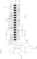
- FIG. 1 shows an example of absolute position coding 1 in the form of a scale.
- the position coding 1 consists at least of a first code track 11 and a second code track 12. These two code tracks 11 and 12 are arranged parallel to one another and running in the measuring direction X.
- the first code track 11 consists of a sequence of first code sequences A.
- the first code sequence A consists of code elements A0 to A4 with the width C.
- Each of the code sequence A is followed by the beginning of this code sequence A again, so that at each interface of the sequential Code sequences A this code sequence A is cyclically continued.
- the second code track 12 consists of a sequence of second code sequences B.
- This second code sequence B consists of code elements B0 to B3, also with the width C, which are arranged such that they are aligned with the code elements of the first code sequence A.
- Each of the code sequence B is followed by the beginning of this code sequence B, so that at each interface of the successive code sequences B, this code sequence B is cyclically continued.
- a code sequence A, B is a sequence of code elements in which a predetermined number of successive code elements, later called sample length, results in different and thus clearly distinguishable combinations of bits, later codewords, over the entire code sequence.
- the first code sequence A has the length L A and the second code sequence B has the length L B , wherein the length L A , L B respectively the number of code elements a code sequence A, B means.
- the two lengths L A and L B differ from each other.
- the principle of the position measurement is based on the beat of several code sequences A, B of different lengths L A and L B , where L A and L B are integer and preferably prime.
- the position coding 1 is scanned optically, for example, by the code elements of the code sequences A, B modulate a light beam position-dependent, so that at the location of a detector unit 21, 22 of a scanning unit 2, a position-dependent light distribution is formed by the detector unit 21, 22 in electrical scanning signals W A , W B is converted.
- the detector unit 21 for scanning the first code track 11 and the detector unit 22 for scanning the second code track 12 are each a line sensor, with a arranged in the measuring direction X sequence of detector elements.
- the detector elements are designed such that each of the code elements in each relative position of at least one of the detector elements is uniquely assigned, and thus from each of the code elements a bit 0 or 1 can be obtained.
- the code elements are reflective or non-reflective, or opaque or non-opaque, wherein the reflective code elements, for example, the bit value 1 and the non-reflective code elements of the bit value 0 is assigned.
- the sequence of these bits within a code sequence A, B forms for the two code sequences A, B each have a codeword W A , W B.
- the scanning signals, that is to say the code words W A , W B are fed to an evaluation unit 3 for forming a position measurement value POS.
- the code words W A , W B respectively of the corresponding decoding T A , T B supplied, which from each of the code words W A , W B one of the code sequences A, B a partial position X A , X B derived and with the aid of these sub-positions X A , X B then forms an absolute POS position.
- the scanning unit 2 is shifted relative to the position coding 1 by the width C or length of a code element, a new code word W A , W B is generated from each of the code sequences A, B.
- the first detector unit 21 for scanning the first code track 11 and the second detector unit 22 for scanning the second code track 12 are preferably of similar design and thus can be produced inexpensively as a standard module in large numbers.
- the two tables T A , T B are provided, the table T A for the code sequence A and the table T B for the code sequence B.
- a certain number of code elements is used to generate the code words W A , W B sampled simultaneously by means of the scanning unit 2.
- the number of sampled code elements each of a code sequence A, B is called sample length L L.
- the code sequences A and B ie the sequence of the code elements, as well as the scan length L L are chosen such that within the section L A at each position in steps of the width C, a unique word W A is generated, which is different from all other words this Section L A distinguishes, and that within the section L B at each position in steps of the width C, a unique word W B is generated, which is different from all the other words of this section L B.
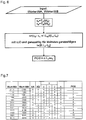
- FIG. 3 An algorithm for determining the positions POS from the sub-positions X A , X B is in FIG. 3 exemplified.
- FIG. 4 A diagram for determining the positions POS in this concrete example is in FIG. 4 shown.
- the bit patterns (words) W A and W B sampled at different instantaneous positions are entered in the first two columns.
- the next two columns list the partial positions X A , X B determined by means of tables T A , T B.
- the next column contains the one after the in FIG. 3 given value n and the right column contains the value after the in FIG. 3 specified position POS.
- the decoding devices T A and T B are advantageously designed as ASIC, wherein the required tables T, ie the required value inventories, are each hardwired during the production of the ASIC.
- the tables T or value stores can also be stored in read-only memories, such as EPROM.
- an incremental track 13 is arranged parallel to the code tracks 11 and 12, whose pitch period corresponds to the width C of a code element of the code tracks 11 and 12.
- the incremental graduation 13 is scanned by means of a detector unit 23, which generates in a known manner a plurality of mutually phase-shifted incremental signals IN.
- These incremental signals IN become an interpolation unit IP which further divides the incremental signals IN and outputs an absolute partial position X IN within the width C.
- the subpositions X A , X B , X IN are fed to a combination unit 31, which therefrom forms the position POS, which is absolute and unambiguous over the measuring range and has a resolution corresponding to the interpolation step of the subposition X IN .
- FIG. 5 a particularly advantageous embodiment of an absolute position measuring device is shown.
- the first code track 11 is arranged and on the other side of the incremental track 13, the code track 12 is arranged.
- a scanning unit consisting of two identical scanning devices 4 and 5.
- Each of the scanning devices 4 and 5 consists of a detector unit 41 or 51 for scanning the incremental track 13 and detector unit 42 or 52 for scanning one of the code tracks 11 and 12, respectively.
- the detector units 41 and 51 are identical and the detector units 42 and 52 are identical.
- the scanning device 4 is identical to the scanning device 5, the scanning device 4 is arranged opposite the scanning device 5 only rotated by 180 °. When evaluating the scanning signals W B , this rotation of the scanning device 5 must be taken into account accordingly.
- the scanning signals IN, W A , W B are fed to an evaluation unit 6 for forming the position POS by means of the tables T A , T B in accordance with the rules explained above.
- the invention can be used particularly advantageously in the case of the optical scanning principle, since an optically scannable position coding 1 with a maximum of possible different positions can be produced reproducibly and thus a particularly high-resolution position measurement is made possible.
- the detector units 21, 22, the decoding devices in the form of the tables T A , T B , and the combination unit 31 are housed together in an opto-ASIC.
- This opto-ASIC preferably additionally includes the detector unit 23 and the interpolation unit IP.
- the invention is not limited to the optical sensing principle, but also in magnetic, inductive and capacitive sensing principles used.
- FIG. 6 An algorithm for determining the positions POS from the sub-positions X A , X B is in FIG. 6 exemplified.
- FIG. 7 A diagram for determining the position POS in this concrete example is in FIG. 7 shown.
- the invention is illustrated by examples with two code sequences A, B in the two code tracks 11 and 12.
- more than two code sequences can also be arranged in more than two tracks.
Description
Die Erfindung betrifft eine absolute Positionscodierung einer Positionsmessvorrichtung gemäß dem Patentanspruch 1.The invention relates to an absolute position coding of a position measuring device according to the
Weiterhin betrifft die Erfindung eine absolute Positionsmessvorrichtung gemäß dem Patentanspruch 6.Furthermore, the invention relates to an absolute position measuring device according to
Auf vielen Gebieten werden zur Bestimmung der Position zweier relativ zueinander bewegter Körper vermehrt absolute Positionsmessvorrichtungen eingesetzt. Absolute Positionsmessvorrichtungen haben gegenüber rein inkremental messenden Systemen den Vorteil, dass in jeder Relativlage auch nach Unterbrechung der Versorgungsenergie sofort eine korrekte Positionsinformation ausgegeben werden kann.In many fields, absolute position measuring devices are increasingly used to determine the position of two relatively moving bodies. Absolute position measuring devices have the advantage over purely incremental measuring systems that correct position information can be output immediately in every relative position even after interruption of the supply energy.
Die absolute Position wird dabei von einer Positionscodierung verkörpert. Besonders Platz sparend ist die Anordnung der Positionscodierung bzw. Positionsinformation in einer einzigen Codespur mit in Messrichtung hintereinander angeordneten Codeelementen. Die Codeelemente sind dabei in pseudozufälliger Verteilung hintereinander angeordnet, so dass eine bestimmte Anzahl von aufeinander folgenden Codeelementen jeweils ein Codewort bildet, das die absolute Position eindeutig definiert. Bei der Verschiebung der Abtasteinrichtung um ein einziges Codeelement wird bereits ein neues Codewort gebildet und über den gesamten absolut zu erfassenden Messbereich steht eine Folge von unterschiedlichen Codewörtern zur Verfügung. Ein derartiger serieller bzw. sequentieller Code wird auch oft als Kettencode oder als Pseudo-Random-Code bezeichnet.The absolute position is represented by a position coding. Particularly space-saving is the arrangement of the position coding or position information in a single code track with successively arranged in the measuring direction code elements. The code elements are arranged in pseudo-random distribution one behind the other, so that a certain number of successive code elements each forms a code word that uniquely defines the absolute position. When shifting the scanning device by a single code element, a new code word is already formed, and a sequence of different code words is available over the entire measuring range to be detected absolutely. Such serial or sequential code is also often called chain code or pseudo-random code.
Zur Bestimmung der absoluten Position aus den abgetasteten Codewörtern - auch Decodierung genannt - wird eine Decodiertabelle eingesetzt, in der jedem Codewort eine Position zugeordnet ist. Zur Zuordnung der absoluten Position zu einem abgetasteten Codewort bildet das Codewort die Adresse für die Decodiertabelle, so dass am Ausgang die für dieses Codewort abgelegte absolute Position ansteht und zur Weiterverarbeitung zur Verfügung steht. Diese nichtflüchtigen Tabellen können heute in einem ASIC hardwareverdrahtet ausgelegt sein, um einen schnellen Zugriff zu ermöglichen.To determine the absolute position of the sampled codewords - also called decoding - a decoding table is used in which each codeword is assigned a position. To assign the absolute position to a sampled codeword, the codeword forms the address for the decoding table, so that the output for that codeword absolute position is pending and available for further processing. These nonvolatile tables can today be hardwired in an ASIC for fast access.
Die Anforderungen an die Auflösung von Positionsmessvorrichtungen werden immer höher, so dass innerhalb eines vorgegebenen Messbereiches viele Positionen eindeutig zu codieren sind. Weiterhin werden bei Längenmessvorrichtungen die absolut zu bestimmenden Längen immer größer. Je mehr Positionen aber codiert werden müssen, umso aufwendiger ist die nachfolgende Decodierung und der Speicherbedarf. Problematisch bei einer seriellen Positionscodierung ist, dass für eine hohe Auflösung und eine große Messlänge sehr viele verschiedene Codewörter generiert und decodiert werden müssen. Erfolgt die Decodierung mittels Tabellen, ist eine große Tabelle erforderlich, in der für jedes mögliche Codewort eine dazugehörige absolute Position abgelegt ist. Erfolgt die Decodierung mittels eines Rechners, führt dies zu relativ langen Rechenzeiten.The requirements for the resolution of position measuring devices are becoming ever higher, so that many positions are to be clearly coded within a predetermined measuring range. Furthermore, in length measuring devices, the absolute lengths to be determined are getting bigger. The more positions, however, have to be coded, the more complex is the subsequent decoding and memory requirements. The problem with serial position coding is that many different codewords have to be generated and decoded for a high resolution and a long measuring length. If the decoding is done by means of tables, a large table is required in which an associated absolute position is stored for each possible codeword. If the decoding by means of a computer, this leads to relatively long computation times.
Die
Aufgabe der Erfindung ist es, eine einfache absolute Positionscodierung für eine Positionsmessvorrichtung anzugeben, mit der große Messbereiche absolut codiert werden können.The object of the invention is to provide a simple absolute position coding for a position measuring device, with the large measuring ranges can be absolutely coded.
Diese Aufgabe wird durch die im Patentanspruch 1 angegebene Positionscodierung gelöst.This object is achieved by the specified in
Diese Positionscodierung weist parallel zueinander angeordnete und in Messrichtung verlaufende Codespuren auf, wobei
die eine Codespur mehrfach aufeinanderfolgend eine erste Codesequenz aufweist, die aus einer Mehrzahl von Codeelementen besteht,
die andere Codespur mehrfach aufeinanderfolgend eine zweite Codesequenz aufweist, die aus einer Mehrzahl von Codeelementen besteht,
die Codesequenzen der einen Codespur und der anderen Codespur unterschiedliche Längen aufweisen, und
die Codeelemente der einen Codespur und der anderen Codespur jeweils in Messrichtung gleiche Abmessungen aufweisen.
Unterschiedliche Längen bedeutet dabei, dass die Länge der einen Codesequenz von der Länge der anderen Codesequenz abweicht, also die eine Codesequenz eine Anzahl von Codeelementen aufweist, die von der Anzahl der Codeelemente der anderen Codesequenz abweicht.This position coding has mutually parallel and extending in the measuring direction code tracks, wherein
a code track having a first code sequence consisting of a plurality of code elements,
the other code track has a second code sequence which consists of a plurality of code elements in multiple succession,
the code sequences of one code track and the other code track have different lengths, and
the code elements of a code track and the other code track each have the same dimensions in the measuring direction.
Different lengths here mean that the length of one code sequence differs from the length of the other code sequence, that is to say that one code sequence has a number of code elements which deviate from the number of code elements of the other code sequence.
Innerhalb des absolut zu bestimmenden Messbereichs sind somit mehrere erste Codesequenzen in der einen Codespur sowie mehrere zweite Codesequenzen in der weiteren Codespur angeordnet.Within the measurement range to be determined absolutely, a plurality of first code sequences in the one code track and a plurality of second code sequences in the further code track are thus arranged.
Besonders vorteilhaft ist es dabei, wenn die Länge der einen Codesequenz sich von der Länge der anderen Codesequenz um 1 unterscheidet. Dabei bedeutet die Länge eine ganzzahlige Anzahl von Codeelementen.It is particularly advantageous if the length of one code sequence differs from the length of the other code sequence by one. The length means an integer number of code elements.
Eine besonders einfache Auswertung ergibt sich, wenn die kürzere der beiden Codesequenzen ein Teil der längeren der beiden Codesequenzen ist.A particularly simple evaluation results when the shorter of the two code sequences is part of the longer of the two code sequences.
Die Erfindung ist nicht auf zwei Codespuren beschränkt, analog zu den zwei erwähnten Codespuren kann eine dritte Codespur vorgesehen sein, die zur zweiten Codespur in analoger Weise abgestuft ist, wie die zweite Codespur zur ersten Codespur.The invention is not limited to two code tracks, analogous to the two mentioned code tracks may be provided a third code track, which is graded to the second code track in an analogous manner as the second code track to the first code track.
Die Positionscodierung kann bei Winkelmessvorrichtungen eingesetzt werden, ist aber bei Längenmessvorrichtungen besonders vorteilhaft einsetzbar, da hier vermehrt die Aufgabe besteht, den absolut zu codierenden Messbereich zu vergrößern.The position coding can be used with angle measuring devices, but can be used particularly advantageously in length measuring devices, since it is increasingly the task to increase the absolutely to be encoded measuring range.
Weiterhin soll mit der Erfindung eine absolute Positionsmessvorrichtung angegeben werden, mit der relativ große Messbereiche absolut gemessen werden können und die Positionsermittlung relativ einfach möglich ist.Furthermore, to be specified with the invention, an absolute position measuring device, with the relatively large measuring ranges can be measured absolutely and the position detection is relatively easy.
Diese Aufgabe wird mit einer Positionsmessvorrichtung mit den Merkmalen des Anspruchs 6 gelöst.This object is achieved with a position measuring device having the features of
Diese Positionsmessvorrichtung weist parallel zueinander angeordnete und in Messrichtung verlaufende Codespuren auf, wobei
die eine Codespur mehrfach aufeinanderfolgend eine erste Codesequenz aufweist, die aus einer Mehrzahl von Codeelementen besteht,
die weitere Codespur mehrfach aufeinanderfolgend eine zweite Codesequenz aufweist, die aus einer Mehrzahl von Codeelementen besteht, die Codesequenzen der einen Codespur und der weiteren Codespur unterschiedliche Längen aufweisen, und
die Codeelemente der einen Codespur und der anderen Codespur jeweils in Messrichtung gleiche Abmessungen aufweisen.This position measuring device has mutually parallel and extending in the measuring direction code tracks, wherein
a code track having a first code sequence consisting of a plurality of code elements,
the further code track has a second code sequence in multiple succession, which consists of a plurality of code elements, the code sequences of one code track and the further code track have different lengths, and
the code elements of a code track and the other code track each have the same dimensions in the measuring direction.
Weiterhin weist die Positionsmessvorrichtung eine Abtasteinheit zur Abtastung der Positionscodierung und eine Auswerteeinheit zur Bildung jeweils einer Teilposition der Codesequenzen und eines Positionsmesswertes aus den Teilpositionen auf.Furthermore, the position measuring device has a scanning unit for scanning the position coding and an evaluation unit for forming in each case a partial position of the code sequences and a position measurement value from the partial positions.
Die Abtasteinheit weist eine erste Detektoreinheit zur Abtastung der einen Codespur und eine zweite Detektoreinheit zur Abtastung der anderen Codespur auf. Vorteilhaft ist es dabei, wenn die erste Detektoreinheit zur Abtastung der einen Codespur und die zweite Detektoreinheit zur Abtastung der anderen Codespur jeweils gleichartig ausgebildet sind.The scanning unit has a first detector unit for scanning the one code track and a second detector unit for scanning the other code track. It is advantageous if the first detector unit for scanning the one code track and the second detector unit for scanning the other code track are each formed identically.
Weitere vorteilhafte Ausgestaltungen der Erfindung sind in den abhängigen Ansprüchen und der nachfolgenden Beschreibung angegeben.Further advantageous embodiments of the invention are specified in the dependent claims and the description below.
Anhand der Zeichnungen werden Ausführungsbeispiele der Erfindung näher erläutert.Reference to the drawings embodiments of the invention will be explained in more detail.
Es zeigt
Figur 1- eine Positionscodierung einer Längenmessvorrichtung in schematischer Darstellung;
Figur 2- eine Abtasteinrichtung zur Abtastung der Positionscodierung gemäß
Figur 1 Figur 3- ein Flussdiagramm und Rechenvorschriften zur Ermittlung der Position mittels der Positionscodierung;
Figur 4- ein Diagramm zur Ermittlung der Position aus gelesenen Bitpattern (Wörtern) anhand eines Beispiels der Positionscodierung;
Figur 5- eine weitere Längenmessvorrichtung in schematischer Darstellung;
Figur 6- ein Flussdiagramm und Rechenvorschriften zur Ermittlung der Position mittels einer weiteren Positionscodierung, und
Figur 7- ein Diagramm zur Ermittlung der Position aus gelesenen Bitpattern (Wörtern) anhand eines Beispiels der weiteren Positionscodierung.
- FIG. 1
- a position coding of a length measuring device in a schematic representation;
- FIG. 2
- a scanning device for scanning the position coding according to
FIG. 1 with an evaluation unit; - FIG. 3
- a flowchart and calculation rules for determining the position by means of the position coding;
- FIG. 4
- a diagram for determining the position of read bit pattern (words) using an example of the position coding;
- FIG. 5
- a further length measuring device in a schematic representation;
- FIG. 6
- a flowchart and calculation instructions for determining the position by means of another position coding, and
- FIG. 7
- a diagram for determining the position of read bit pattern (words) using an example of further position coding.
Die erste Codespur 11 besteht aus einer Abfolge von ersten Codesequenzen A. Die erste Codesequenz A besteht aus Codeelementen A0 bis A4 mit der Breite C. An jede der Codesequenz A schließt sich der Anfang dieser Codesequenz A wieder an, so dass an jeder Nahtstelle der aufeinanderfolgenden Codesequenzen A diese Codesequenz A zyklisch fortgesetzt ist.
Die zweite Codespur 12 besteht aus einer Abfolge von zweiten Codesequenzen B. Diese zweite Codesequenz B besteht aus Codeelementen B0 bis B3, ebenfalls mit der Breite C, die derart angeordnet sind, dass sie zu den Codeelementen der ersten Codesequenz A fluchten. An jede der Codesequenz B schließt sich der Anfang dieser Codesequenz B wieder an, so dass an jeder Nahtstelle der aufeinanderfolgenden Codesequenzen B diese Codesequenz B zyklisch fortgesetzt ist.The
The
Eine Codesequenz A, B ist dabei eine Abfolge von Codeelementen, bei der eine vorgegebene Anzahl aufeinanderfolgender Codeelemente, später Abtastlänge bezeichnet, über die gesamte Codesequenz unterschiedliche und somit eindeutig voneinander unterscheidbare Kombinationen von Bits, später Codewörter bezeichnet, ergibt.A code sequence A, B is a sequence of code elements in which a predetermined number of successive code elements, later called sample length, results in different and thus clearly distinguishable combinations of bits, later codewords, over the entire code sequence.
Die erste Codesequenz A hat die Länge LA und die zweite Codesequenz B die Länge LB, wobei die Länge LA, LB jeweils die Anzahl der Codeelemente einer Codesequenz A, B bedeutet. Die beiden Längen LA und LB unterscheiden sich voneinander.The first code sequence A has the length L A and the second code sequence B has the length L B , wherein the length L A , L B respectively the number of code elements a code sequence A, B means. The two lengths L A and L B differ from each other.
Das Prinzip der Positionsmessung beruht auf der Schwebung von mehreren Codesequenzen A, B unterschiedlicher Längen LA und LB, wobei LA und LB ganzzahlig und vorzugsweise teilerfremd.The principle of the position measurement is based on the beat of several code sequences A, B of different lengths L A and L B , where L A and L B are integer and preferably prime.
Mit diesen zwei Codesequenzen A, B können K mögliche Positionen eindeutig codiert werden, wobei die Anzahl K = KGV (LA, LB) ist, mit
- KGV = kleinstes gemeinsames Vielfaches von LA und LB
- LA = Länge der ersten Codesequenz A;
- LB = Länge der zweiten Codesequenz B.
- KGV = least common multiple of L A and L B
- L A = length of the first code sequence A;
- L B = length of the second code sequence B.
Der maximale Messbereich (also die maximale Länge in Messrichtung X, nach der sich das Bitmuster der beiden Spuren 11 und 12 wiederholt) ist mit zwei Codesequenzen A, B absolut codierbar, wenn sich die Länge LA von der Länge LB um 1 unterscheidet: ![]()
![]()
Zur Positionsmessung wird die Positionscodierung 1 beispielsweise optisch abgetastet, indem die Codeelemente der Codesequenzen A, B ein Lichtbündel positionsabhängig modulieren, so dass am Ort einer Detektoreinheit 21, 22 einer Abtasteinheit 2 eine positionsabhängige Lichtverteilung entsteht, die von der Detektoreinheit 21, 22 in elektrische Abtastsignale WA, WB gewandelt wird. Die Detektoreinheit 21 zur Abtastung der ersten Codespur 11 sowie die Detektoreinheit 22 zur Abtastung der zweiten Codespur 12 ist jeweils ein Zeilensensor, mit einer in Messrichtung X angeordneten Folge von Detektorelementen. Die Detektorelemente sind derart ausgebildet, dass jedem der Codeelemente in jeder Relativlage zumindest eines der Detektorelemente eindeutig zugeordnet ist, und somit aus jedem der Codeelemente ein Bit 0 oder 1 gewonnen werden kann. Hierzu sind beim optischen Abtastprinzip die Codeelemente reflektierend oder nichtreflektierend, bzw. opak oder nichtopak, wobei den reflektierenden Codeelementen beispielsweise der Bitwert 1 und den nichtreflektierenden Codeelementen der Bitwert 0 zugeordnet wird. Die Abfolge dieser Bits innerhalb einer Codesequenz A, B bildet für die beiden Codesequenzen A, B jeweils ein Codewort WA, WB. Die Abtastsignale, also die Codeworte WA, WB, werden einer Auswerteeinheit 3 zur Bildung eines Positionsmesswertes POS zugeführt. Konkret werden die Codeworte WA, WB jeweils der entsprechenden Decodiereinrichtung TA, TB zugeführt, welche aus jedem der Codeworte WA, WB einer der Codesequenzen A, B eine Teilposition XA, XB ableitet und mit Hilfe dieser Teilpositionen XA, XB dann daraus eine absolute Position POS bildet. Bei einer Verschiebung der Abtasteinheit 2 gegenüber der Positionscodierung 1 um die Breite C bzw. Länge eines Codeelementes wird aus jeder der Codesequenzen A, B jeweils ein neues Codewort WA, WB erzeugt.For position measurement, the
Die erste Detektoreinheit 21 zur Abtastung der ersten Codespur 11 und die zweite Detektoreinheit 22 zur Abtastung der zweiten Codespur 12 sind vorzugsweise gleichartig ausgebildet und somit als Standardbaustein in großen Stückzahlen kostengünstig herstellbar.The
Zur Decodierung der Codewörter WA, WB sind die zwei Tabellen TA, TB vorgesehen, die Tabelle TA für die Codesequenz A und die Tabelle TB für die Codesequenz B. Eine bestimmte Anzahl von Codeelementen wird zur Generierung der Codewörter WA, WB mittels der Abtasteinheit 2 gleichzeitig abgetastet. Die Anzahl der abgetasteten Codeelemente jeweils einer Codesequenz A, B wird Abtastlänge LL bezeichnet.For the decoding of the code words W A , W B , the two tables T A , T B are provided, the table T A for the code sequence A and the table T B for the code sequence B. A certain number of code elements is used to generate the code words W A , W B sampled simultaneously by means of the
Die Codesequenzen A und B, also die Abfolge der Codeelemente, sowie die Abtastlänge LL sind derart gewählt, dass innerhalb des Abschnitts LA an jeder Position in Schritten der Breite C ein eindeutiges Wort WA generiert wird, das sich von allen anderen Wörtern dieses Abschnitts LA unterscheidet, und dass innerhalb des Abschnitts LB an jeder Position in Schritten der Breite C ein eindeutiges Wort WB generiert wird, das sich von allen anderen Worten dieses Abschnitts LB unterscheidet.The code sequences A and B, ie the sequence of the code elements, as well as the scan length L L are chosen such that within the section L A at each position in steps of the width C, a unique word W A is generated, which is different from all other words this Section L A distinguishes, and that within the section L B at each position in steps of the width C, a unique word W B is generated, which is different from all the other words of this section L B.
Mit der in
- Länge der Codesequenz A: LA = 5
- Codesequenz A: A0A1A2A3A4
- Länge der Codesequenz B: LB = 4
- Codesequenz B: B0B1B2B3
- Abtastlänge: LL = 4

- Length of the code sequence A: L A = 5
- Code sequence A: A 0 A 1 A 2 A 3 A 4
- Length of the code sequence B: L B = 4
- Code sequence B: B 0 B 1 B 2 B 3
- Scanning length: L L = 4
Die Tabelle TA für die Codesequenz A:
Die Tabelle TB für die Codesequenz B:
Diese beiden Tabellen TA, TB beinhalten zusammen 9 Einträge, mit diesen 9 Einträgen sind 20 verschiedene Positionen POS eindeutig decodierbar, und zwar in Schritten entsprechend einer Breite C eines Codeelementes.These two tables T A , T B together contain 9 entries, with these 9 entries 20 different positions POS are uniquely decodable, in steps corresponding to a width C of a code element.
Ein Algorithmus zur Ermittlung der Positionen POS aus den Teilpositionen XA, XB ist in
Der Vorteil einer derartigen Codierung besteht darin, dass eine Decodiereinrichtung in Form von Tabellen TA und TB jeweils nur die relativ kurzen seriellen Codesequenzen A und B decodieren müssen. Erfolgt die Decodierung mittels Tabellen, sind nur mehrere kleine Tabellen erforderlich. Es sind sehr viel weniger Tabelleneinträge notwendig, als absolute Positionen ausgebbar sind.The advantage of such a coding is that a decoding device in the form of tables T A and T B respectively only have to decode the relatively short serial code sequences A and B. If the decoding is done using tables, only several small tables are required. There are much fewer table entries necessary than absolute positions can be issued.
Anhand eines konkreten Beispiels wird die Erfindung noch näher erläutert:
- Länge der Codesequenz A: LA = 5
- Codesequenz A: 01111
- Länge der Codesequenz B: LB = 4
- Codesequenz B: 0100
- Abtastlänge: LL = 4 in jeder der beiden Codespuren 11 und 12

- Codespur 11: 01111011110111101111
- Codespur 12: 01000100010001000100
- Length of the code sequence A: L A = 5
- Code sequence A: 01111
- Length of the code sequence B: L B = 4
- Code sequence B: 0100
- Sampling length: L L = 4 in each of the two
code tracks 11 and 12 - Code track 11: 01111011110111101111
- Code track 12: 01000100010001000100
Die Tabelle TA für die Codesequenz A:
Die Tabelle TB für die Codesequenz B:
Ein Diagramm zur Ermittlung der Positionen POS bei diesem konkreten Beispiel ist in
Die Decodiereinrichtungen TA und TB sind vorteilhaft als ASIC ausgebildet, wobei die erforderlichen Tabellen T, also die erforderlichen Wertevorräte, jeweils bei der Fertigung des ASIC's fest verdrahtet ausgebildet sind. Alternativ können die Tabellen T bzw. Wertevorräte aber auch in Festwertspeichern, wie EPROM abgelegt sein.The decoding devices T A and T B are advantageously designed as ASIC, wherein the required tables T, ie the required value inventories, are each hardwired during the production of the ASIC. Alternatively, however, the tables T or value stores can also be stored in read-only memories, such as EPROM.
Soll der durch die beiden Codespuren 11 und 12 ermittelte Positionsmesswert weiter aufgelöst werden, können noch weitere Spuren mit absoluten Codierungen oder mit Inkrementalteilungen vorgesehen sein. Im Beispiel ist parallel zu den Codespuren 11 und 12 eine Inkrementalspur 13 angeordnet, deren Teilungsperiode der Breite C eines Codeelementes der Codespuren 11 und 12 entspricht. Durch entsprechende Dimensionierung der Inkrementalspur 13 ist es möglich, die Breite C eines Codeelementes weiter zu unterteilen. Hierzu wird die Inkrementalteilung 13 mittels einer Detektoreinheit 23 abgetastet, die in bekannter Weise mehrere gegeneinander phasenverschobene Inkrementalsignale IN erzeugt. Diese Inkrementalsignale IN werden einer Interpolationseinheit IP zugeführt, welche die Inkrementalsignale IN weiter unterteilt und eine absolute Teilposition XIN innerhalb der Breite C ausgibt. Die Teilpositionen XA, XB, XIN werden einer Kombinationseinheit 31 zugeführt, welche daraus die Position POS bildet, die über den Messbereich absolut und eindeutig ist und eine Auflösung entsprechend dem Interpolationsschritt der Teilposition XIN aufweist.If the position measurement value ascertained by the two
In
Die Abtastsignale IN, WA, WB werden einer Auswerteeinheit 6 zur Bildung der Position POS mittels der Tabellen TA, TB entsprechend der oben erläuterten Regeln zugeführt.The scanning signals IN, W A , W B are fed to an
Die Erfindung ist beim optischen Abtastprinzip besonders vorteilhaft einsetzbar, da eine optisch abtastbare Positionscodierung 1 mit maximal möglich verschiedenen Positionen reproduzierbar herstellbar ist und damit eine besonders hochauflösende Positionsmessung ermöglicht wird. Dabei können bei dem Beispiel gemäß
Die Erfindung ist aber nicht auf das optische Abtastprinzip beschränkt, sondern auch bei magnetischen, induktiven sowie kapazitiven Abtastprinzipien einsetzbar.The invention is not limited to the optical sensing principle, but also in magnetic, inductive and capacitive sensing principles used.
Eine einfache Auswertung ergibt sich, wenn die kürzere der Codesequenzen ein Teil der längeren der Codesequenzen ist. Im erörterten Beispiel würde dies bedeuten, dass die Abfolge der Codeelemente A0 bis A3 der Abfolge der Codeelemente B0 bis B3 entspricht. Die zur Decodierung erforderliche Tabelle TA entspricht dabei der Tabelle TB, so dass für diesen Bereich für beide Codesequenzen A, B nur eine gemeinsame Tabelle erforderlich ist. Zur vollständigen Decodierung müssen dann nur noch für die zyklischen Fortsetzungen der Codesequenzen A und B individuelle Tabellen geschaffen werden.A simple evaluation results when the shorter of the code sequences is part of the longer of the code sequences. In the example discussed, this would mean that the sequence of code elements A0 to A3 corresponds to the sequence of code elements B0 to B3. The table T A required for decoding corresponds to the table T B , so that only one common table is required for this area for both code sequences A, B. For complete decoding then individual tables must be created only for the cyclic continuations of the code sequences A and B.
Dass sich die Längen der Codesequenzen um 1 unterscheiden, ist besonders vorteilhaft. Es liegt aber auch im Rahmen der Erfindung, wenn sich die beiden Codesequenzen in ihren Längen beispielsweise um eine Potenz von 2 unterscheiden. Bei einer derartigen Abstufung kann die Auswertung besonders einfach realisiert werden, da binäre Berechnungen einfach durchführbar sind.That the lengths of the code sequences differ by 1 is particularly advantageous. However, it is also within the scope of the invention if the two code sequences differ in their lengths, for example by a power of 2. With such a gradation, the evaluation can be realized particularly easily, since binary calculations are easy to carry out.
Anhand eines konkreten Beispiels hierzu wird die Erfindung noch näher erläutert:
- Länge der Codesequenz A: LA = 6
- Codesequenz A: 011110
- Länge der Codesequenz B: LB = 4
- Codesequenz B: 0100
- Abtastlänge: LL = 4 in jeder der beiden Codespuren

- erste Spur aus Codesequenz A: 011110011110
- zweite Spur aus Codesequenz B: 010001000100
- Length of the code sequence A: L A = 6
- Code sequence A: 011110
- Length of the code sequence B: L B = 4
- Code sequence B: 0100
- Sampling length: L L = 4 in each of the two code tracks
- first lane from code sequence A: 011110011110
- second lane from code sequence B: 010001000100
Ein Algorithmus zur Ermittlung der Positionen POS aus den Teilpositionen XA, XB ist in
Ein Diagramm zur Ermittlung der Position POS bei diesem konkreten Beispiel ist in
Die Erfinding ist anhand von Beispielen mit zwei Codesequenzen A, B in den zwei Codespuren 11 und 12 erläutert. Um einen noch größeren Messbereich absolut zu codieren, können auch mehr als zwei Codesequenzen in mehr als zwei Spuren angeordnet werden.The invention is illustrated by examples with two code sequences A, B in the two
Claims (11)
- Absolute position code for a position measuring device, having code tracks (11, 12) arranged parallel to each other and extending in the measuring direction (X), wherein
the one code track (1) has a first code sequence (A) many times in succession, which comprises a plurality of code elements,
the other code track (12) has a second code sequence (B) many times in succession, which comprises a plurality of code elements,
the length (LA) of the one code sequence (A) differs from the length (LB) of the other code sequence (B), wherein the length (LA, LB) respectively signifies the integer number of the code elements of the code sequence (A, B),
the code elements of the one code sequence (A) and the code elements of the other code sequence (B) have the same dimension (C) in the measuring direction (X). - Absolute position code according to Claim 1, characterized in that the length (LA) of the one code sequence (A) differs from the length (LB) of the other code sequence (B) by 1.
- Absolute position code according to Claim 1, characterized in that the two code sequences differ in their length by a power of 2.
- Absolute position code according to one of the preceding claims, characterized in that the shorter of the two code sequences (B) is part of the longer code sequence (A).
- Absolute position code according to one of the preceding claims, characterized in that at least one incremental track (13) is arranged in addition to the code tracks (11, 12).
- Absolute position measuring device having an absolute position code (1, 10) according to one of Claims 1 to 5,
comprising two code tracks (11, 12) arranged parallel to each other and extending in the measuring direction (X), wherein
the one code track (11) has a first code sequence (A) many times in succession, which comprises a plurality of code elements,
the other code track (12) has a second code sequence (B) many times in succession, which comprises a plurality of code elements,
the code sequences (A, B) of the one code track (11) and the other code track (11) have different lengths (LA, LB), wherein the length (LA, LB) respectively signifies the integer number of the code elements of the code sequence (A, B),
the code elements of the one code sequence (11) and the code elements of the other code sequence (11) have the same dimension (C) in the measuring direction (X), and
having a scanning unit (2, 4, 5) for scanning the position code (1, 10) and for forming words (W), and having
an evaluation unit (3, 6) for forming a position measured value (POS) from the words (W). - Absolute position measuring device according to Claim 6, characterized in that the scanning unit (2, 4, 5) has a first detector unit (21, 42) for scanning the one code track (11) and a second detector unit (22, 52) for scanning the other code track (12), wherein the two detector units (21, 22, 42, 52) are formed identically.
- Absolute position measuring device according to one of the preceding Claims 6 or 7, characterized in that at least one incremental track (13) is arranged parallel to the code tracks (11, 12).
- Absolute position measuring device according to Claim 8, characterized in that the evaluation unit (3, 6) has a combination unit (31), which is designed to form the position measured value (POS) from the words (W) obtained by scanning the code tracks (11, 12) and from incremental signals (IN) obtained by scanning the incremental track (13).
- Absolute position measuring device according to one of the preceding Claims 8 or 9, characterized in that the one code track (11) is arranged on one side beside the incremental track (13), and the other code track (12) is arranged on the other side beside the incremental track (13).
- Absolute position measuring device according to Claim 10, characterized in that the scanning unit comprises a first scanning device (4) and a second scanning device (5), wherein the two scanning devices (4, 5) are formed identically, in that the first scanning device (4) comprises a detector unit (42) for scanning the one code track (11) and a detector unit (41) for scanning the incremental track (13), and the second scanning device (5) comprises a detector unit (52) for scanning the other code track (12) and a detector unit (51) for scanning the incremental track (13).
Applications Claiming Priority (2)
| Application Number | Priority Date | Filing Date | Title |
|---|---|---|---|
| DE102008053977A DE102008053977A1 (en) | 2008-10-30 | 2008-10-30 | Absolute position coding and position measuring device |
| PCT/EP2009/007014 WO2010049046A1 (en) | 2008-10-30 | 2009-09-30 | Absolute position measuring device |
Publications (2)
| Publication Number | Publication Date |
|---|---|
| EP2342539A1 EP2342539A1 (en) | 2011-07-13 |
| EP2342539B1 true EP2342539B1 (en) | 2017-09-06 |
Family
ID=41582172
Family Applications (1)
| Application Number | Title | Priority Date | Filing Date |
|---|---|---|---|
| EP09778775.8A Active EP2342539B1 (en) | 2008-10-30 | 2009-09-30 | Absolute position measuring device |
Country Status (4)
| Country | Link |
|---|---|
| EP (1) | EP2342539B1 (en) |
| DE (1) | DE102008053977A1 (en) |
| ES (1) | ES2641763T3 (en) |
| WO (1) | WO2010049046A1 (en) |
Families Citing this family (3)
| Publication number | Priority date | Publication date | Assignee | Title |
|---|---|---|---|---|
| EP2674731B1 (en) * | 2012-06-13 | 2015-09-02 | Dr. Johannes Heidenhain GmbH | Position measuring device |
| DE102014010759B4 (en) | 2014-07-17 | 2020-06-04 | Nils Remmers | Procedure for determining a position |
| DE102016109257A1 (en) * | 2016-05-19 | 2017-11-23 | Ic-Haus Gmbh | Position measuring device for measuring an absolute position |
Family Cites Families (3)
| Publication number | Priority date | Publication date | Assignee | Title |
|---|---|---|---|---|
| US5135081A (en) * | 1991-05-01 | 1992-08-04 | United States Elevator Corp. | Elevator position sensing system using coded vertical tape |
| US5739775A (en) * | 1993-07-22 | 1998-04-14 | Bourns, Inc. | Digital input and control device |
| JP4924878B2 (en) | 2006-11-06 | 2012-04-25 | 株式会社ニコン | Absolute encoder |
-
2008
- 2008-10-30 DE DE102008053977A patent/DE102008053977A1/en not_active Withdrawn
-
2009
- 2009-09-30 ES ES09778775.8T patent/ES2641763T3/en active Active
- 2009-09-30 WO PCT/EP2009/007014 patent/WO2010049046A1/en active Application Filing
- 2009-09-30 EP EP09778775.8A patent/EP2342539B1/en active Active
Non-Patent Citations (1)
| Title |
|---|
| None * |
Also Published As
| Publication number | Publication date |
|---|---|
| DE102008053977A1 (en) | 2010-05-06 |
| WO2010049046A1 (en) | 2010-05-06 |
| ES2641763T3 (en) | 2017-11-13 |
| EP2342539A1 (en) | 2011-07-13 |
Similar Documents
| Publication | Publication Date | Title |
|---|---|---|
| EP1821073B1 (en) | Position measuring device | |
| EP1400778B1 (en) | Position measuring device | |
| EP3121565B1 (en) | Absolute position determination | |
| EP1329696B1 (en) | Absolute position detector with scale | |
| EP1468254B1 (en) | Position measuring device | |
| EP1403623B1 (en) | Method for determining an absolute position | |
| DE19545949A1 (en) | Digital absolute position encoder and coding method | |
| EP2342540B1 (en) | Absolute angle code and angle measuring device | |
| EP1557646B1 (en) | Rotary encoder and method for scanning the code disk of a rotary encoder | |
| DE102006010161B4 (en) | Code structure for a position measuring device and position measuring device with such a code structure | |
| EP1195579B1 (en) | Method for determining the absolute position | |
| EP3179216A1 (en) | Absolute measurement length measuring system and method of operating the same | |
| EP2342539B1 (en) | Absolute position measuring device | |
| EP2340417B1 (en) | Absolute position measuring device | |
| EP2869031B1 (en) | Position measuring device | |
| EP1206684B1 (en) | Position-measuring device | |
| EP1770375B1 (en) | Position measuring device with two scales whose coded tracks overlap one another | |
| EP2271897B1 (en) | Angle-measuring device and line of products comprising said angle-measuring devices | |
| EP2340418B1 (en) | Absolute position code and position measuring device | |
| DE102014103514B4 (en) | Method for detecting the angle of rotation | |
| EP4242595B1 (en) | Position, length or angle determination device and method | |
| EP3924696B1 (en) | Position-measuring device for measuring an absolute position | |
| DE202004011508U1 (en) | Rotary encoder | |
| DE102021110583A1 (en) | Sensor device and method for determining an absolute position | |
| DE2811449B2 (en) | Digital servo angle controller |
Legal Events
| Date | Code | Title | Description |
|---|---|---|---|
| PUAI | Public reference made under article 153(3) epc to a published international application that has entered the european phase |
Free format text: ORIGINAL CODE: 0009012 |
|
| 17P | Request for examination filed |
Effective date: 20110530 |
|
| AK | Designated contracting states |
Kind code of ref document: A1 Designated state(s): AT BE BG CH CY CZ DE DK EE ES FI FR GB GR HR HU IE IS IT LI LT LU LV MC MK MT NL NO PL PT RO SE SI SK SM TR |
|
| AX | Request for extension of the european patent |
Extension state: AL BA RS |
|
| RIN1 | Information on inventor provided before grant (corrected) |
Inventor name: LINGK, CHRISTOPH Inventor name: SCHUERMANN, THOMAS Inventor name: MAYER, ELMAR Inventor name: BENNER, ULRICH |
|
| DAX | Request for extension of the european patent (deleted) | ||
| GRAP | Despatch of communication of intention to grant a patent |
Free format text: ORIGINAL CODE: EPIDOSNIGR1 |
|
| INTG | Intention to grant announced |
Effective date: 20170620 |
|
| GRAS | Grant fee paid |
Free format text: ORIGINAL CODE: EPIDOSNIGR3 |
|
| GRAA | (expected) grant |
Free format text: ORIGINAL CODE: 0009210 |
|
| AK | Designated contracting states |
Kind code of ref document: B1 Designated state(s): AT BE BG CH CY CZ DE DK EE ES FI FR GB GR HR HU IE IS IT LI LT LU LV MC MK MT NL NO PL PT RO SE SI SK SM TR |
|
| REG | Reference to a national code |
Ref country code: GB Ref legal event code: FG4D Free format text: NOT ENGLISH |
|
| REG | Reference to a national code |
Ref country code: CH Ref legal event code: EP Ref country code: AT Ref legal event code: REF Ref document number: 926368 Country of ref document: AT Kind code of ref document: T Effective date: 20170915 |
|
| REG | Reference to a national code |
Ref country code: CH Ref legal event code: NV Representative=s name: ICB INGENIEURS CONSEILS EN BREVETS SA, CH |
|
| REG | Reference to a national code |
Ref country code: IE Ref legal event code: FG4D Free format text: LANGUAGE OF EP DOCUMENT: GERMAN |
|
| REG | Reference to a national code |
Ref country code: DE Ref legal event code: R096 Ref document number: 502009014341 Country of ref document: DE |
|
| REG | Reference to a national code |
Ref country code: ES Ref legal event code: FG2A Ref document number: 2641763 Country of ref document: ES Kind code of ref document: T3 Effective date: 20171113 |
|
| REG | Reference to a national code |
Ref country code: NL Ref legal event code: MP Effective date: 20170906 |
|
| REG | Reference to a national code |
Ref country code: LT Ref legal event code: MG4D |
|
| PG25 | Lapsed in a contracting state [announced via postgrant information from national office to epo] |
Ref country code: SE Free format text: LAPSE BECAUSE OF FAILURE TO SUBMIT A TRANSLATION OF THE DESCRIPTION OR TO PAY THE FEE WITHIN THE PRESCRIBED TIME-LIMIT Effective date: 20170906 Ref country code: FI Free format text: LAPSE BECAUSE OF FAILURE TO SUBMIT A TRANSLATION OF THE DESCRIPTION OR TO PAY THE FEE WITHIN THE PRESCRIBED TIME-LIMIT Effective date: 20170906 Ref country code: LT Free format text: LAPSE BECAUSE OF FAILURE TO SUBMIT A TRANSLATION OF THE DESCRIPTION OR TO PAY THE FEE WITHIN THE PRESCRIBED TIME-LIMIT Effective date: 20170906 Ref country code: HR Free format text: LAPSE BECAUSE OF FAILURE TO SUBMIT A TRANSLATION OF THE DESCRIPTION OR TO PAY THE FEE WITHIN THE PRESCRIBED TIME-LIMIT Effective date: 20170906 Ref country code: NO Free format text: LAPSE BECAUSE OF FAILURE TO SUBMIT A TRANSLATION OF THE DESCRIPTION OR TO PAY THE FEE WITHIN THE PRESCRIBED TIME-LIMIT Effective date: 20171206 |
|
| PG25 | Lapsed in a contracting state [announced via postgrant information from national office to epo] |
Ref country code: LV Free format text: LAPSE BECAUSE OF FAILURE TO SUBMIT A TRANSLATION OF THE DESCRIPTION OR TO PAY THE FEE WITHIN THE PRESCRIBED TIME-LIMIT Effective date: 20170906 Ref country code: GR Free format text: LAPSE BECAUSE OF FAILURE TO SUBMIT A TRANSLATION OF THE DESCRIPTION OR TO PAY THE FEE WITHIN THE PRESCRIBED TIME-LIMIT Effective date: 20171207 Ref country code: BG Free format text: LAPSE BECAUSE OF FAILURE TO SUBMIT A TRANSLATION OF THE DESCRIPTION OR TO PAY THE FEE WITHIN THE PRESCRIBED TIME-LIMIT Effective date: 20171206 |
|
| PG25 | Lapsed in a contracting state [announced via postgrant information from national office to epo] |
Ref country code: NL Free format text: LAPSE BECAUSE OF FAILURE TO SUBMIT A TRANSLATION OF THE DESCRIPTION OR TO PAY THE FEE WITHIN THE PRESCRIBED TIME-LIMIT Effective date: 20170906 |
|
| PG25 | Lapsed in a contracting state [announced via postgrant information from national office to epo] |
Ref country code: PL Free format text: LAPSE BECAUSE OF FAILURE TO SUBMIT A TRANSLATION OF THE DESCRIPTION OR TO PAY THE FEE WITHIN THE PRESCRIBED TIME-LIMIT Effective date: 20170906 Ref country code: RO Free format text: LAPSE BECAUSE OF FAILURE TO SUBMIT A TRANSLATION OF THE DESCRIPTION OR TO PAY THE FEE WITHIN THE PRESCRIBED TIME-LIMIT Effective date: 20170906 Ref country code: CZ Free format text: LAPSE BECAUSE OF FAILURE TO SUBMIT A TRANSLATION OF THE DESCRIPTION OR TO PAY THE FEE WITHIN THE PRESCRIBED TIME-LIMIT Effective date: 20170906 |
|
| PG25 | Lapsed in a contracting state [announced via postgrant information from national office to epo] |
Ref country code: SM Free format text: LAPSE BECAUSE OF FAILURE TO SUBMIT A TRANSLATION OF THE DESCRIPTION OR TO PAY THE FEE WITHIN THE PRESCRIBED TIME-LIMIT Effective date: 20170906 Ref country code: SK Free format text: LAPSE BECAUSE OF FAILURE TO SUBMIT A TRANSLATION OF THE DESCRIPTION OR TO PAY THE FEE WITHIN THE PRESCRIBED TIME-LIMIT Effective date: 20170906 Ref country code: IS Free format text: LAPSE BECAUSE OF FAILURE TO SUBMIT A TRANSLATION OF THE DESCRIPTION OR TO PAY THE FEE WITHIN THE PRESCRIBED TIME-LIMIT Effective date: 20180106 Ref country code: EE Free format text: LAPSE BECAUSE OF FAILURE TO SUBMIT A TRANSLATION OF THE DESCRIPTION OR TO PAY THE FEE WITHIN THE PRESCRIBED TIME-LIMIT Effective date: 20170906 |
|
| REG | Reference to a national code |
Ref country code: DE Ref legal event code: R097 Ref document number: 502009014341 Country of ref document: DE |
|
| REG | Reference to a national code |
Ref country code: IE Ref legal event code: MM4A |
|
| REG | Reference to a national code |
Ref country code: BE Ref legal event code: MM Effective date: 20170930 |
|
| PG25 | Lapsed in a contracting state [announced via postgrant information from national office to epo] |
Ref country code: MC Free format text: LAPSE BECAUSE OF FAILURE TO SUBMIT A TRANSLATION OF THE DESCRIPTION OR TO PAY THE FEE WITHIN THE PRESCRIBED TIME-LIMIT Effective date: 20170906 Ref country code: LU Free format text: LAPSE BECAUSE OF NON-PAYMENT OF DUE FEES Effective date: 20170930 |
|
| PLBE | No opposition filed within time limit |
Free format text: ORIGINAL CODE: 0009261 |
|
| STAA | Information on the status of an ep patent application or granted ep patent |
Free format text: STATUS: NO OPPOSITION FILED WITHIN TIME LIMIT |
|
| PG25 | Lapsed in a contracting state [announced via postgrant information from national office to epo] |
Ref country code: DK Free format text: LAPSE BECAUSE OF FAILURE TO SUBMIT A TRANSLATION OF THE DESCRIPTION OR TO PAY THE FEE WITHIN THE PRESCRIBED TIME-LIMIT Effective date: 20170906 Ref country code: IE Free format text: LAPSE BECAUSE OF NON-PAYMENT OF DUE FEES Effective date: 20170930 |
|
| 26N | No opposition filed |
Effective date: 20180607 |
|
| REG | Reference to a national code |
Ref country code: FR Ref legal event code: ST Effective date: 20180713 |
|
| PG25 | Lapsed in a contracting state [announced via postgrant information from national office to epo] |
Ref country code: BE Free format text: LAPSE BECAUSE OF NON-PAYMENT OF DUE FEES Effective date: 20170930 Ref country code: SI Free format text: LAPSE BECAUSE OF FAILURE TO SUBMIT A TRANSLATION OF THE DESCRIPTION OR TO PAY THE FEE WITHIN THE PRESCRIBED TIME-LIMIT Effective date: 20170906 |
|
| PG25 | Lapsed in a contracting state [announced via postgrant information from national office to epo] |
Ref country code: MT Free format text: LAPSE BECAUSE OF FAILURE TO SUBMIT A TRANSLATION OF THE DESCRIPTION OR TO PAY THE FEE WITHIN THE PRESCRIBED TIME-LIMIT Effective date: 20170906 |
|
| PG25 | Lapsed in a contracting state [announced via postgrant information from national office to epo] |
Ref country code: FR Free format text: LAPSE BECAUSE OF NON-PAYMENT OF DUE FEES Effective date: 20171106 |
|
| REG | Reference to a national code |
Ref country code: AT Ref legal event code: MM01 Ref document number: 926368 Country of ref document: AT Kind code of ref document: T Effective date: 20170930 |
|
| PG25 | Lapsed in a contracting state [announced via postgrant information from national office to epo] |
Ref country code: AT Free format text: LAPSE BECAUSE OF NON-PAYMENT OF DUE FEES Effective date: 20170930 |
|
| PG25 | Lapsed in a contracting state [announced via postgrant information from national office to epo] |
Ref country code: HU Free format text: LAPSE BECAUSE OF FAILURE TO SUBMIT A TRANSLATION OF THE DESCRIPTION OR TO PAY THE FEE WITHIN THE PRESCRIBED TIME-LIMIT; INVALID AB INITIO Effective date: 20090930 |
|
| PG25 | Lapsed in a contracting state [announced via postgrant information from national office to epo] |
Ref country code: CY Free format text: LAPSE BECAUSE OF NON-PAYMENT OF DUE FEES Effective date: 20170906 |
|
| PG25 | Lapsed in a contracting state [announced via postgrant information from national office to epo] |
Ref country code: MK Free format text: LAPSE BECAUSE OF FAILURE TO SUBMIT A TRANSLATION OF THE DESCRIPTION OR TO PAY THE FEE WITHIN THE PRESCRIBED TIME-LIMIT Effective date: 20170906 |
|
| PG25 | Lapsed in a contracting state [announced via postgrant information from national office to epo] |
Ref country code: TR Free format text: LAPSE BECAUSE OF FAILURE TO SUBMIT A TRANSLATION OF THE DESCRIPTION OR TO PAY THE FEE WITHIN THE PRESCRIBED TIME-LIMIT Effective date: 20170906 |
|
| PG25 | Lapsed in a contracting state [announced via postgrant information from national office to epo] |
Ref country code: PT Free format text: LAPSE BECAUSE OF FAILURE TO SUBMIT A TRANSLATION OF THE DESCRIPTION OR TO PAY THE FEE WITHIN THE PRESCRIBED TIME-LIMIT Effective date: 20170906 |
|
| PGFP | Annual fee paid to national office [announced via postgrant information from national office to epo] |
Ref country code: GB Payment date: 20230920 Year of fee payment: 15 |
|
| PGFP | Annual fee paid to national office [announced via postgrant information from national office to epo] |
Ref country code: DE Payment date: 20230920 Year of fee payment: 15 |
|
| PGFP | Annual fee paid to national office [announced via postgrant information from national office to epo] |
Ref country code: ES Payment date: 20231124 Year of fee payment: 15 |
|
| PGFP | Annual fee paid to national office [announced via postgrant information from national office to epo] |
Ref country code: IT Payment date: 20230927 Year of fee payment: 15 Ref country code: CH Payment date: 20231001 Year of fee payment: 15 |