EP2340417B1 - Absolute position measuring device - Google Patents
Absolute position measuring device Download PDFInfo
- Publication number
- EP2340417B1 EP2340417B1 EP09778793.1A EP09778793A EP2340417B1 EP 2340417 B1 EP2340417 B1 EP 2340417B1 EP 09778793 A EP09778793 A EP 09778793A EP 2340417 B1 EP2340417 B1 EP 2340417B1
- Authority
- EP
- European Patent Office
- Prior art keywords
- code
- sequence
- code sequence
- angle
- absolute angle
- Prior art date
- Legal status (The legal status is an assumption and is not a legal conclusion. Google has not performed a legal analysis and makes no representation as to the accuracy of the status listed.)
- Active
Links
- 125000004122 cyclic group Chemical group 0.000 claims description 11
- 230000015654 memory Effects 0.000 claims description 8
- 238000005070 sampling Methods 0.000 description 6
- 238000005259 measurement Methods 0.000 description 5
- OVGWMUWIRHGGJP-WVDJAODQSA-N (z)-7-[(1s,3r,4r,5s)-3-[(e,3r)-3-hydroxyoct-1-enyl]-6-thiabicyclo[3.1.1]heptan-4-yl]hept-5-enoic acid Chemical compound OC(=O)CCC\C=C/C[C@@H]1[C@@H](/C=C/[C@H](O)CCCCC)C[C@@H]2S[C@H]1C2 OVGWMUWIRHGGJP-WVDJAODQSA-N 0.000 description 4
- 101100161473 Arabidopsis thaliana ABCB25 gene Proteins 0.000 description 4
- 101000988961 Escherichia coli Heat-stable enterotoxin A2 Proteins 0.000 description 4
- 101100096893 Mus musculus Sult2a1 gene Proteins 0.000 description 4
- 101150081243 STA1 gene Proteins 0.000 description 4
- 238000010586 diagram Methods 0.000 description 4
- 230000001419 dependent effect Effects 0.000 description 3
- 230000003287 optical effect Effects 0.000 description 3
- 238000010009 beating Methods 0.000 description 2
- 238000004519 manufacturing process Methods 0.000 description 2
- 230000006978 adaptation Effects 0.000 description 1
- 230000015572 biosynthetic process Effects 0.000 description 1
- 238000011156 evaluation Methods 0.000 description 1
- 230000001939 inductive effect Effects 0.000 description 1
- 230000000737 periodic effect Effects 0.000 description 1
- 230000000717 retained effect Effects 0.000 description 1
- 230000035939 shock Effects 0.000 description 1
- JUJBNYBVVQSIOU-UHFFFAOYSA-M sodium;4-[2-(4-iodophenyl)-3-(4-nitrophenyl)tetrazol-2-ium-5-yl]benzene-1,3-disulfonate Chemical compound [Na+].C1=CC([N+](=O)[O-])=CC=C1N1[N+](C=2C=CC(I)=CC=2)=NC(C=2C(=CC(=CC=2)S([O-])(=O)=O)S([O-])(=O)=O)=N1 JUJBNYBVVQSIOU-UHFFFAOYSA-M 0.000 description 1
Images


Classifications
-
- G—PHYSICS
- G01—MEASURING; TESTING
- G01D—MEASURING NOT SPECIALLY ADAPTED FOR A SPECIFIC VARIABLE; ARRANGEMENTS FOR MEASURING TWO OR MORE VARIABLES NOT COVERED IN A SINGLE OTHER SUBCLASS; TARIFF METERING APPARATUS; MEASURING OR TESTING NOT OTHERWISE PROVIDED FOR
- G01D5/00—Mechanical means for transferring the output of a sensing member; Means for converting the output of a sensing member to another variable where the form or nature of the sensing member does not constrain the means for converting; Transducers not specially adapted for a specific variable
- G01D5/26—Mechanical means for transferring the output of a sensing member; Means for converting the output of a sensing member to another variable where the form or nature of the sensing member does not constrain the means for converting; Transducers not specially adapted for a specific variable characterised by optical transfer means, i.e. using infrared, visible, or ultraviolet light
- G01D5/32—Mechanical means for transferring the output of a sensing member; Means for converting the output of a sensing member to another variable where the form or nature of the sensing member does not constrain the means for converting; Transducers not specially adapted for a specific variable characterised by optical transfer means, i.e. using infrared, visible, or ultraviolet light with attenuation or whole or partial obturation of beams of light
- G01D5/34—Mechanical means for transferring the output of a sensing member; Means for converting the output of a sensing member to another variable where the form or nature of the sensing member does not constrain the means for converting; Transducers not specially adapted for a specific variable characterised by optical transfer means, i.e. using infrared, visible, or ultraviolet light with attenuation or whole or partial obturation of beams of light the beams of light being detected by photocells
- G01D5/347—Mechanical means for transferring the output of a sensing member; Means for converting the output of a sensing member to another variable where the form or nature of the sensing member does not constrain the means for converting; Transducers not specially adapted for a specific variable characterised by optical transfer means, i.e. using infrared, visible, or ultraviolet light with attenuation or whole or partial obturation of beams of light the beams of light being detected by photocells using displacement encoding scales
- G01D5/3473—Circular or rotary encoders
-
- G—PHYSICS
- G01—MEASURING; TESTING
- G01D—MEASURING NOT SPECIALLY ADAPTED FOR A SPECIFIC VARIABLE; ARRANGEMENTS FOR MEASURING TWO OR MORE VARIABLES NOT COVERED IN A SINGLE OTHER SUBCLASS; TARIFF METERING APPARATUS; MEASURING OR TESTING NOT OTHERWISE PROVIDED FOR
- G01D5/00—Mechanical means for transferring the output of a sensing member; Means for converting the output of a sensing member to another variable where the form or nature of the sensing member does not constrain the means for converting; Transducers not specially adapted for a specific variable
- G01D5/12—Mechanical means for transferring the output of a sensing member; Means for converting the output of a sensing member to another variable where the form or nature of the sensing member does not constrain the means for converting; Transducers not specially adapted for a specific variable using electric or magnetic means
- G01D5/244—Mechanical means for transferring the output of a sensing member; Means for converting the output of a sensing member to another variable where the form or nature of the sensing member does not constrain the means for converting; Transducers not specially adapted for a specific variable using electric or magnetic means influencing characteristics of pulses or pulse trains; generating pulses or pulse trains
- G01D5/245—Mechanical means for transferring the output of a sensing member; Means for converting the output of a sensing member to another variable where the form or nature of the sensing member does not constrain the means for converting; Transducers not specially adapted for a specific variable using electric or magnetic means influencing characteristics of pulses or pulse trains; generating pulses or pulse trains using a variable number of pulses in a train
- G01D5/2454—Encoders incorporating incremental and absolute signals
- G01D5/2455—Encoders incorporating incremental and absolute signals with incremental and absolute tracks on the same encoder
-
- G—PHYSICS
- G01—MEASURING; TESTING
- G01D—MEASURING NOT SPECIALLY ADAPTED FOR A SPECIFIC VARIABLE; ARRANGEMENTS FOR MEASURING TWO OR MORE VARIABLES NOT COVERED IN A SINGLE OTHER SUBCLASS; TARIFF METERING APPARATUS; MEASURING OR TESTING NOT OTHERWISE PROVIDED FOR
- G01D5/00—Mechanical means for transferring the output of a sensing member; Means for converting the output of a sensing member to another variable where the form or nature of the sensing member does not constrain the means for converting; Transducers not specially adapted for a specific variable
- G01D5/12—Mechanical means for transferring the output of a sensing member; Means for converting the output of a sensing member to another variable where the form or nature of the sensing member does not constrain the means for converting; Transducers not specially adapted for a specific variable using electric or magnetic means
- G01D5/244—Mechanical means for transferring the output of a sensing member; Means for converting the output of a sensing member to another variable where the form or nature of the sensing member does not constrain the means for converting; Transducers not specially adapted for a specific variable using electric or magnetic means influencing characteristics of pulses or pulse trains; generating pulses or pulse trains
- G01D5/249—Mechanical means for transferring the output of a sensing member; Means for converting the output of a sensing member to another variable where the form or nature of the sensing member does not constrain the means for converting; Transducers not specially adapted for a specific variable using electric or magnetic means influencing characteristics of pulses or pulse trains; generating pulses or pulse trains using pulse code
- G01D5/2492—Pulse stream
- G01D5/2495—Pseudo-random code
-
- G—PHYSICS
- G01—MEASURING; TESTING
- G01D—MEASURING NOT SPECIALLY ADAPTED FOR A SPECIFIC VARIABLE; ARRANGEMENTS FOR MEASURING TWO OR MORE VARIABLES NOT COVERED IN A SINGLE OTHER SUBCLASS; TARIFF METERING APPARATUS; MEASURING OR TESTING NOT OTHERWISE PROVIDED FOR
- G01D5/00—Mechanical means for transferring the output of a sensing member; Means for converting the output of a sensing member to another variable where the form or nature of the sensing member does not constrain the means for converting; Transducers not specially adapted for a specific variable
- G01D5/12—Mechanical means for transferring the output of a sensing member; Means for converting the output of a sensing member to another variable where the form or nature of the sensing member does not constrain the means for converting; Transducers not specially adapted for a specific variable using electric or magnetic means
- G01D5/244—Mechanical means for transferring the output of a sensing member; Means for converting the output of a sensing member to another variable where the form or nature of the sensing member does not constrain the means for converting; Transducers not specially adapted for a specific variable using electric or magnetic means influencing characteristics of pulses or pulse trains; generating pulses or pulse trains
- G01D5/249—Mechanical means for transferring the output of a sensing member; Means for converting the output of a sensing member to another variable where the form or nature of the sensing member does not constrain the means for converting; Transducers not specially adapted for a specific variable using electric or magnetic means influencing characteristics of pulses or pulse trains; generating pulses or pulse trains using pulse code
- G01D5/2497—Absolute encoders
Definitions
- Absolute angle measuring devices are increasingly used to determine the position of two relatively moving bodies.
- Absolute angle measuring devices have the advantage over purely incremental measuring systems that correct position information can be output immediately in any relative position even after interruption of the supply energy.
- the absolute position is embodied by an angle coding.
- Particularly space-saving is the arrangement of the position information in a single code track with successively arranged in the measuring direction code elements.
- the code elements are arranged in pseudo-random distribution one behind the other, so that a certain number of successive code elements each forms a code word that uniquely defines the absolute position.
- a new code word is already formed and over the entire absolute extent to be detected is a sequence of different code words available.
- serial or sequential code is also often called chain code or pseudo random code (PRC).
- a decoding table is used in which each codeword is assigned a position.
- the codeword forms the address for the decoding table, so that the absolute position stored for this codeword is present at the output and is available for further processing.
- the US 6,330,522 B1 shows a measure of how an angle coding and an angle measuring device can be designed to reduce the cost of decoding.
- a first code sequence and a second code sequence are arranged in mutually parallel tracks over 360 °.
- the first code sequence is located five times over 360 ° and the second code sequence is located fourteen times over 360 °.
- the code sequences include different angular sectors.
- the bit width of the first code sequence differs from the bit width of the second code sequence.
- the decoding device has a first value store for decoding the first code sequence and a second value store for decoding the second code sequence.
- the absolute position is unique by the combination of both partial positions at each position over 360 °.
- the object of the invention is therefore to provide an angle coding, with which any number of positions over 360 ° can be uniquely coded, and with an angle encoder in a simple decoding of the generated by sampling this angular coding sequences of codewords is made possible.
- an absolute angle measuring device is specified with such an angle coding.
- the absolute angle coding has several code sequences arranged within 360 °, which in combination unambiguously absolutely encode the 360 °, of which a first code sequence consisting of a sequence of code elements, including a first angle sector and arranged several times in succession, and cyclically repeated several times, a second code sequence consisting of a sequence of code elements, including a second angle sector and arranged several times in succession, and cyclically repeated several times, wherein the first angle sector is different from the second angle sector, and at least one of the code sequences within the 360 ° is only partially formed and forms a joint with the subsequent code sequence.
- At least one of the two code sequences is only partially applied once within 360 °, and this part is connected to the next code sequence.
- this code sequence is interrupted, since this produces a collision region at which a new sequence of code elements, ie. H. new bitpattern or words, arises.
- New bitpattern means that these bitpatterns are not part of the code sequences and their cyclic continuations.
- the code sequences are arranged in a circle on a disk or over the circumference of a drum.
- a code element is in each case an area of the angle coding, from which one bit can be derived.
- Code sequence means a sequence of code elements that define different positions in the raster of a code element over the entire length of the code sequence.
- Cyclically continued code sequence means that the beginning of this same code sequence reconnects at the end of the code sequence.
- the angle coding formed according to the invention now makes it possible, in particular over 360 ° 2 k, to code different positions, preferably k> 4 and integer.
- the code elements of the first code sequence and the second code sequence preferably each include equal angular sectors. Given this, the size of an angle sector can be more easily defined by the number of code elements.
- the maximum number of different positions is obtained if the length of the first code sequence differs from the length of the second code sequence by one.
- the length of the first code sequence is the number of code elements of the first code sequence and the length of the second code sequence is the number of code elements of the second code sequence.
- first code sequence and the second code sequence are arranged in a common track, in which a part of the first code sequence and a part of the second code sequence are arranged alternately.
- Each code element of the first code sequence is followed by a single code element of the second code sequence and a code element of the second code sequence is followed by a single code element of the first code sequence.
- At least one incremental track may be arranged concentrically with the absolute angle coding.
- the pitch period of this incremental track is, for example, a fraction of the width of a code element of the code sequences A, B.
- An angle measuring device now has a detector arrangement for scanning the first and the second code sequence of the angle coding and for generating code words, as well as a decoding device for decoding the code words and for generating position values.
- the decoder device has a first value store for decoding a first sequence of codewords, which respectively arises during the sampling of one of the first code sequences and their cyclic continuation, and a second value store for decoding a second sequence of codewords, each of which is used in the sampling of one of the second code sequences and their cyclic continuation arises, and the decoding device has a further store of value which is suitable for decoding the joint of the first code sequence and / or the second code sequence.
- the vernier principle is used.
- two serial code sequences A, B are used, which include different angle sectors L A and L B.
- the unique absolute position POS is now the combination of partial positions x A , x B of the multiple serial Code sequences A, B won.
- the advantage of such encoding is that a decoder 3 must decode only the relatively short multiple serial code sequences A, B and their cyclic continuations, and then the unique position POS over 360 ° by relatively simple relationships from these decoded code sequences A, B can be determined. If the decoding is done using tables, only several small tables are required. There are much fewer table entries necessary than absolute positions can be issued.
- FIG. 1 a first inventively formed absolute angle coding 1 and angle measuring device is shown schematically.
- the angle coding 1 is designed in such a way that it defines a unique absolute position POS at each position within a full revolution, that is, over 360 ° endlessly.
- the angle coding 1 consists of a consecutively arranged sequence of code elements A0 to A4 or B0 to B3, each including an angle sector of the same size.
- the first sequence of code elements A0 to A4 is arranged in a first track and forms the first code sequence A
- the second sequence of code elements B0 to B3 is arranged in a second track and forms the second code sequence B.
- the two code tracks are arranged concentrically to each other. It is particularly advantageous if the code elements of the two code tracks are aligned with each other.
- the principle of position measurement is based on the beat of two code sequences A, B of different sizes of the angle sector L A and L B enclosing them.
- the size of the angle sectors L A and L B differ only slightly from each other, so that the angle sector L A is not an integer multiple of the angle sector L B.
- the size of the angular sectors of the code sequences A, B can be represented by the number of code elements for simplified further explanation.
- L A and L B are integer and preferably as number of code elements prime.
- the maximum length M 1max to be decoded results when L A differs from L B by one.
- the first code sequence A is with the bit string A 0 A 1 A 2 A 3 ... A LA-1 given the length L A.
- the second code sequence B is the bit sequence B 0 B 1 B 2 B 3 ... B LB-1 given the length L B.
- the angle coding 1 is scanned optically, for example, by the code elements modulate a light beam position-dependent, so that at the location of a detector array 2 of a scanning device, a position-dependent light distribution is formed, which is converted by the detector assembly 2 into electrical scanning signals w.
- the detector arrangement 2 is a line sensor, with a sequence of detector elements arranged in the measuring direction.
- the detector elements are designed such that each of the code elements in each relative position of at least one of the detector elements is uniquely assigned, and thus from each of the code elements a bit 0 or 1 can be obtained.
- the code elements are reflective or non-reflective, or opaque or non-opaque, wherein the reflective code elements, for example, the bit value 1 and the non-reflective code elements of the bit value 0 is assigned.
- the sequence of these bits (bit patterns) within a code sequence A, B forms a codeword w for the two code sequences A, B in each case.
- the scanning signals that is to say the code words w, are supplied to a decoding device 3, which derives a partial position x A , x B from each of the code words w of one of the code sequences A, B and then forms an absolute position POS from these partial positions x A , x B.
- a new code word w is generated from each of the code sequences A, B.
- the detector arrangement 2 in each case has a detector 2A, 2B for scanning one of the code sequences A, B, each having a scanning length L L1 .
- L L1 scanning length
- the code sequence A is interrupted at the junction ST, since one of the code sequences A is cut off at the junction and not completely applied.
- the code sequence A now emerge when crossing the joint ST with the detector array 2A new bit patterns that do not occur in the table T A.
- the bit A 0 is not followed by A 1 , but again A 0 and then only A 1 .
- the new positions of the code sequence A at the joint ST are summarized in a new table T STA ("ST" for joint; "A" for the code sequence A).
- This additional table T STA provides the value stock for decoding the words W STA generated at the burst ST by the detector 2A.
- the number of entries is (L L1 -1) and is in Example 3.
- the position POS is now determined outside of the joint ST from the partial positions x A and x B and when crossing the joint ST from the partial positions x A and x STA .
- Table T A for code sequence A Bitpattern Word W A Partial position x A 0111 W A0 0 1111 W A1 1 1110 W A2 2 1101 W A3 3 1011 W A4 4 Table T B : for code sequence B Bitpattern Word W B Partial position x B 0100 W B0 0 1000 W B1 1 0001 W B2 2 0010 W B3 3 Table T STA : Bitpattern Word W STA Partial position x STA 1100 W STA0 0 1001 W STA1 1 0011 W STA2 2
- FIG. 2 A flowchart and calculation instructions for determining the position POS from the read bitpattern is in FIG. 2 shown.
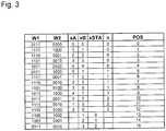
- FIG. 3 shows a diagram for determining the position POS from the read bit pattern (words) using the specific example.
- angle coding 1 can be supplemented by another track or several further tracks with absolute codes or with incremental divisions.
- an incremental track 4 in parallel, ie concentrically, to the tracks with the code sequences A, B.
- the graduation period of this incremental track 4 is advantageously a fraction of the width of a code element of the code sequences A, B. Within an angle sector of a code element, a number greater than or equal to 1 incremental graduation periods is advantageously arranged.
- the incremental graduation 4 is scanned by means of a further, not shown, detector unit, which generates in a known manner a plurality of mutually phase-shifted incremental signals.
- the angle coding 10 is in turn given by the lengths L A and L B of the code sequences A and B, where L A ⁇ L B and L A and L B is an integer. Since the code elements all enclose the same angle sector, the lengths L A and L B are again defined as the number of code elements of the corresponding code sequence A, B.
- the total position POS is here by means of the calculation rules R 1 and R 2 according to the FIG. 6 calculated.
- At the joint ST at least one of the code sequences A, B is cut off and thus the cyclical continuation of at least one of the code sequences (here the code sequence A) is interrupted.
- This area via this junction ST requires separate treatment with at least one separate table, because the bit patterns generated during the sampling via this junction ST are not present in the tables T A and / or T B.
- code sequences A and B are given by: Code sequence A: A 0 A 1 A 2 A 3 A 4 Code sequence B: B 0 B 1 B 2 B 3
- Tables T A and T B are then given by: Table T ⁇ sub> A ⁇ / sub>: for code sequence A Bitpattern Word w Partial position x A A 0 A 1 A 2 A 3 W A0 0 A 1 A 2 A 3 A 4 W A1 1 A 2 A 3 A 4 A 0 W A2 2 A 3 A 4 A 0 A 1 W A3 3 A 4 A 0 A 1 A 2 W A4 4 Bitpattern Word w Partial position x B B 0 B 1 B 2 B 3 W B0 0 B 1 B 2 B 3 B 0 W B1 1 B 2 B 3 B 0 B 1 W B2 2 B 3 B 0 B 1 B 2 W B3 3 3 3 3
- the code sequence A is interrupted at the joint ST.
- the code sequence A now dive when crossing the joint ST with the detector array 20 new bit patterns that do not occur in the table T A.
- the bit A 0 is not followed by A 1 , but again A 0 and then only A 1 .
- the new positions of the code sequence A at the joint ST can be summarized in a new table T STA ("ST" for joint; "A" for the code sequence A).
- calculation rules R1, R2, R3 and R4 for determining the position POS are in FIG. 6 It should be noted that these calculation rules R1, R2, R3 and R4 are given by way of example only, since other relationships may be used here as well.
- Code sequence A 01111
- Code sequence B 0100
- FIG. 7 1 is a diagram for determining the position POS from read bit patterns (words) w using the example of the second angle coding 10.
- words read bit patterns
- FIG. 5 In the second and third columns, those from the words w follow FIG. 5 detected words w1 and w2.
- the six further columns show the query as to whether the words w1 and w2 are found in the tables T A , T B , T STA .
- a "1" defines it found.
- the next column labeled "RV" defines the calculation rule R1, R2, R3 and R4 to be used.
- the following three columns show the subpositions x A , x B and x STA .
- the next column contains the one after the in FIG. 6 calculated value "n".
- the last column now contains the position POS calculated according to the corresponding calculation rules R1, R2, R3 or R4.
- the decoding device 3, 30 is advantageously formed as an ASIC, wherein the required tables T, so the required value inventories, each hardwired in the manufacture of the ASIC's are formed.
- the tables T or value stores can also be stored in read-only memories, such as EPROM.
- a mixed form of memory is particularly advantageous, on the one hand rapid access to the memory data, ie the value stores, being achieved and, on the other hand, rapid adaptation to the intended use.
- This is carried out by on the one hand the value stock T A , T B for the code sequences A and B and their cyclic sequels is hard wired executed and additionally a still programmable memory after the mask is provided, in this programmable memory of the individually required value store T ST , T STA of the shock ST is stored, so the tables T ST and T STA .
- the programmable memory is a read-only memory and is designed, for example, as an EPROM.
- the tables T ST and T STA can be fixed in the manufacture of the angle measuring device, so stored. Alternatively, the tables T ST and T STA can also be generated and stored automatically by means of a predetermined formation specification, or the generation is carried out by means of a calibration run in which each sampled bit pattern (word) is assigned and stored a position.
- the absolute angle coding 10 As in FIG. 4 shown schematically, the absolute angle coding 10 according to the example of FIG. 1 be supplemented by an incremental 40.
- a number advantageously equal to or greater than 1, incremental graduation periods is again arranged within an angle sector of a code element.
- the invention can be used particularly advantageously in the optical scanning principle, since optically scannable angle coding 1, 10 is possible with a maximum various positions over 360 ° (one revolution of the angle coding 1, 10) can be reproduced produced and thus a particularly high-resolution position measurement is possible.
- the detector arrangement 2, 20 and the decoding device 3, 30 may be housed together in an opto-ASIC.
- the invention is not limited to the optical sensing principle, but also in magnetic, inductive and capacitive sensing principles used.
Description
Auf vielen Gebieten werden zur Bestimmung der Position zweier relativ zueinander bewegter Körper vermehrt absolute Winkelmessvorrichtungen eingesetzt. Absolute Winkelmessvorrichtungen haben gegenüber rein inkremental messenden Systemen den Vorteil, dass in jeder Relativlage auch nach Unterbrechung der Versorgungsenergie sofort eine korrekte Positionsinformation ausgegeben werden kann.In many fields, absolute angle measuring devices are increasingly used to determine the position of two relatively moving bodies. Absolute angle measuring devices have the advantage over purely incremental measuring systems that correct position information can be output immediately in any relative position even after interruption of the supply energy.
Die absolute Position wird dabei von einer Winkelcodierung verkörpert. Besonders Platz sparend ist die Anordnung der Positionsinformation in einer einzigen Codespur mit in Messrichtung hintereinander angeordneten Codeelementen. Die Codeelemente sind dabei in pseudozufälliger Verteilung hintereinander angeordnet, so dass eine bestimmte Anzahl von aufeinander folgenden Codeelementen jeweils ein Codewort bildet, das die absolute Position eindeutig definiert. Bei der Verschiebung der Abtasteinrichtung um ein einziges Codeelement wird bereits ein neues Codewort gebildet und über den gesamten absolut zu erfassenden Umfang steht eine Folge von unterschiedlichen Codewörtern zur Verfügung. Ein derartiger serieller bzw. sequentieller Code wird auch oft als Kettencode oder als Pseudo-Random-Code (PRC) bezeichnet.The absolute position is embodied by an angle coding. Particularly space-saving is the arrangement of the position information in a single code track with successively arranged in the measuring direction code elements. The code elements are arranged in pseudo-random distribution one behind the other, so that a certain number of successive code elements each forms a code word that uniquely defines the absolute position. When shifting the scanning device to a single code element, a new code word is already formed and over the entire absolute extent to be detected is a sequence of different code words available. Such serial or sequential code is also often called chain code or pseudo random code (PRC).
Zur Bestimmung der absoluten Position aus den abgetasteten Codewörtern - auch Decodierung genannt - wird eine Decodiertabelle eingesetzt, in der jedem Codewort eine Position zugeordnet ist. Zur Zuordnung der absoluten Position zu einem abgetasteten Codewort bildet das Codewort die Adresse für die Decodiertabelle, so dass am Ausgang die für dieses Codewort abgelegte absolute Position ansteht und zur Weiterverarbeitung zur Verfügung steht. Diese nichtflüchtigen Tabellen können heute in einem ASIC hardwareverdrahtet ausgelegt sein, um einen schneilen Zugriff zu ermöglichen.To determine the absolute position of the sampled codewords - also called decoding - a decoding table is used in which each codeword is assigned a position. To assign the absolute position to a sampled codeword, the codeword forms the address for the decoding table, so that the absolute position stored for this codeword is present at the output and is available for further processing. These nonvolatile tables can today be hardwired in an ASIC to allow for quick access.
Die Anforderungen an die Auflösung von Winkelmessvorrichtungen werden immer höher, so dass über 360° viele Positionen eindeutig zu codieren sind.The requirements for the resolution of angle measuring devices are getting higher, so that over 360 ° many positions are clearly encoded.
Je mehr Positionen codiert werden müssen, umso aufwendiger ist die nachfolgende Decodierung. Problematisch bei einer seriellen Codierung ist, dass für eine hohe Auflösung sehr viele verschiedene Codewörter generiert und decodiert werden müssen. Erfolgt die Decodierung mittels Tabellen, ist eine große Tabelle erforderlich, in der für jedes mögliche Codewort eine dazugehörige absolute Position abgelegt ist. Erfolgt die Decodierung mittels eines Rechners, führt dies zu relativ langen Rechenzeiten.The more positions that have to be coded, the more complicated the subsequent decoding. A problem with serial coding is that very many different codewords have to be generated and decoded for a high resolution. If the decoding is done by means of tables, a large table is required in which an associated absolute position is stored for each possible codeword. If the decoding by means of a computer, this leads to relatively long computation times.
Die
Nachteilig dabei ist, dass über 360° nur eine Anzahl von Positionen codierbar ist, die jeweils ein ganzzahliges Vielfaches der Länge beider Codesequenzen ist.The disadvantage here is that over 360 ° only a number of positions is codable, each of which is an integral multiple of the length of both code sequences.
Aufgabe der Erfindung ist es daher, eine Winkelcodierung anzugeben, mit der eine beliebige Anzahl von Positionen über 360° eindeutig codiert werden kann, und mit der in einer Winkelmessvorrichtung eine einfache Decodierung der durch Abtastung dieser Winkelcodierung generierten Folgen von Codewörtern ermöglicht wird.The object of the invention is therefore to provide an angle coding, with which any number of positions over 360 ° can be uniquely coded, and with an angle encoder in a simple decoding of the generated by sampling this angular coding sequences of codewords is made possible.
Diese Aufgabe wird durch die im Anspruch 1 angegebene Winkelcodierung gelöst.This object is achieved by the angular coding specified in
Im Anspruch 11 ist eine absolute Winkelmessvorrichtung mit einer derartigen Winkelcodierung angegeben.In
Die absolute Winkelcodierung weist mehrere innerhalb von 360° angeordnete Codesequenzen auf, die in Kombination die 360° eindeutig absolut codieren, von denen
eine erste Codesequenz, bestehend aus einer Folge von Codeelementen, einen ersten Winkelsektor einschließt und mehrmals aufeinanderfolgend angeordnet ist, sowie mehrmals zyklisch fortgesetzt ist,
eine zweite Codesequenz, bestehend aus einer Folge von Codeelementen, einen zweiten Winkelsektor einschließt und mehrmals aufeinanderfolgend angeordnet ist, sowie mehrmals zyklisch fortgesetzt ist, wobei
der erste Winkelsektor ungleich dem zweiten Winkelsektor ist, und zumindest eine der Codesequenzen innerhalb der 360° nur teilweise ausgebildet ist und eine Stoßstelle mit der nachfolgenden Codesequenz bildet.The absolute angle coding has several code sequences arranged within 360 °, which in combination unambiguously absolutely encode the 360 °, of which
a first code sequence consisting of a sequence of code elements, including a first angle sector and arranged several times in succession, and cyclically repeated several times,
a second code sequence consisting of a sequence of code elements, including a second angle sector and arranged several times in succession, and cyclically repeated several times, wherein
the first angle sector is different from the second angle sector, and at least one of the code sequences within the 360 ° is only partially formed and forms a joint with the subsequent code sequence.
In anderen Worten ausgedrückt, ist zumindest eine der beiden Codesequenzen einmal innerhalb 360° nur teilweise aufgetragen, und dieser Teil an die nächste Codesequenz angeschlossen. An dieser Anschlussstelle ist diese Codesequenz unterbrochen, da hier ein Stoßbereich entsteht, an dem bei der Abtastung eine neue Folge von Codeelementen, d. h. neue Bitpattern bzw. Wörter, entsteht. Neue Bitpattern bedeutet, dass diese Bitpattern nicht Bestandteil der Codesequenzen und ihrer zyklischen Fortsetzungen sind.In other words, at least one of the two code sequences is only partially applied once within 360 °, and this part is connected to the next code sequence. At this juncture, this code sequence is interrupted, since this produces a collision region at which a new sequence of code elements, ie. H. new bitpattern or words, arises. New bitpattern means that these bitpatterns are not part of the code sequences and their cyclic continuations.
Die Codesequenzen sind dabei kreisförmig an einer Scheibe oder über den Umfang einer Trommel angeordnet.The code sequences are arranged in a circle on a disk or over the circumference of a drum.
Ein Codeelement ist jeweils ein Bereich der Winkelcodierung, aus dem ein Bit ableitbar ist.A code element is in each case an area of the angle coding, from which one bit can be derived.
Codesequenz bedeutet eine Abfolge von Codeelementen, die über die Gesamtlänge der Codesequenz unterschiedliche Positionen im Raster eines Codeelementes definiert.Code sequence means a sequence of code elements that define different positions in the raster of a code element over the entire length of the code sequence.
Zyklisch fortgesetzte Codesequenz bedeutet, dass sich am Ende der Codesequenz der Anfang dieser gleichen Codesequenz wieder anschließt.Cyclically continued code sequence means that the beginning of this same code sequence reconnects at the end of the code sequence.
Die erfindungsgemäß ausgebildete Winkelcodierung ermöglicht nun insbesondere über 360° 2k verschiedene Positionen zu codieren, mit vorzugsweise k>4 und ganzzahlig.The angle coding formed according to the invention now makes it possible, in particular over 360 ° 2 k, to code different positions, preferably k> 4 and integer.
Die Codeelemente der ersten Codesequenz und der zweiten Codesequenz schließen vorzugsweise jeweils gleiche Winkelsektoren ein. Dies vorausgesetzt, kann die Größe eines Winkelsektors besonders einfach durch die Anzahl von Codeelementen definiert werden.The code elements of the first code sequence and the second code sequence preferably each include equal angular sectors. Given this, the size of an angle sector can be more easily defined by the number of code elements.
Die maximale Anzahl von verschiedenen Positionen erhält man, wenn sich die Länge der ersten Codesequenz von der Länge der zweiten Codesequenz um 1 unterscheidet. Dabei ist die Länge der ersten Codesequenz die Anzahl der Codeelemente der ersten Codesequenz und die Länge der zweiten Codesequenz die Anzahl der Codeelemente der zweiten Codesequenz.The maximum number of different positions is obtained if the length of the first code sequence differs from the length of the second code sequence by one. The length of the first code sequence is the number of code elements of the first code sequence and the length of the second code sequence is the number of code elements of the second code sequence.
Eine relativ einfache Auswertung der durch Abtastung der Codesequenzen gewonnenen Wörter (Bitpattern) ergibt sich, wenn die erste Codesequenz und die zweite Codesequenz in verschiedenen Spuren angeordnet sind.A relatively simple evaluation of the words obtained by sampling the code sequences (bit patterns) results when the first code sequence and the second code sequence are arranged in different tracks.
Bei der Anordnung in zwei Spuren ist in den beiden Spuren jeweils über 360° eine gleiche Anzahl
- M1 < KGV (LA , LB) von Codeelementen angeordnet, mit
- KGV (LA , LB) = kleinstes gemeinsames Vielfaches von LA und LB
- LA = ganzzahlige Anzahl der Codeelemente der ersten Codesequenz
- LB = ganzzahlige Anzahl der Codeelemente der zweiten Codesequenz.
- M 1 <KGV (L A , L B ) of code elements arranged with
- KGV (L A , L B ) = least common multiple of L A and L B
- L A = integer number of code elements of the first code sequence
- L B = integer number of code elements of the second code sequence.
Über die 360° lassen sich mehr unterschiedliche Positionen codieren, wenn die erste Codesequenz und die zweite Codesequenz in einer gemeinsamen Spur angeordnet sind, indem jeweils ein Teil der ersten Codesequenz und ein Teil der zweiten Codesequenz abwechselnd angeordnet ist. Insbesondere folgt auf ein Codeelement der ersten Codesequenz jeweils ein einziges Codeelement der zweiten Codesequenz und auf ein Codeelement der zweiten Codesequenz jeweils ein einziges Codeelement der ersten Codesequenz.Over the 360 °, more different positions can be coded if the first code sequence and the second code sequence are arranged in a common track, in which a part of the first code sequence and a part of the second code sequence are arranged alternately. Especially Each code element of the first code sequence is followed by a single code element of the second code sequence and a code element of the second code sequence is followed by a single code element of the first code sequence.
Bei der Anordnung in einer gemeinsamen Spur ist in dieser Spur über 360° eine Anzahl
- M2 < 2 * KGV (LA , LB) Codeelemente angeordnet ist, mit
- KGV (LA , LB) = kleinstes gemeinsames Vielfaches von LA und LB
- LA = Anzahl der Codeelemente der ersten Codesequenz
- LB = Anzahl der Codeelemente der zweiten Codesequenz.
- M 2 <2 * KGV (L A , L B ) code elements is arranged with
- KGV (L A , L B ) = least common multiple of L A and L B
- L A = number of code elements of the first code sequence
- L B = number of code elements of the second code sequence.
Soll der durch die beiden Codesequenzen A, B ermittelte Positionswert weiter aufgelöst werden, kann konzentrisch zu der absoluten Winkelcodierung zumindest eine Inkrementalspur angeordnet sein. Die Teilungsperiode dieser Inkrementalspur ist beispielsweise ein Bruchteil der Breite eines Codeelementes der Codesequenzen A, B.If the position value determined by the two code sequences A, B is to be resolved further, at least one incremental track may be arranged concentrically with the absolute angle coding. The pitch period of this incremental track is, for example, a fraction of the width of a code element of the code sequences A, B.
Eine Winkelmessvorrichtung weist nun eine Detektoranordnung zur Abtastung der ersten und der zweiten Codesequenz der Winkelcodierung und zur Generierung von Codewörtern auf, sowie eine Dekodiereinrichtung zur Dekodierung der Codewörter und zur Generierung von Positionswerten.An angle measuring device now has a detector arrangement for scanning the first and the second code sequence of the angle coding and for generating code words, as well as a decoding device for decoding the code words and for generating position values.
Die Dekodiereinrichtung weist einen ersten Wertevorrat zur Dekodierung einer ersten Folge von Codewörtern auf, die jeweils bei der Abtastung einer der ersten Codesequenzen sowie ihrer zyklischen Fortsetzung entsteht, und einen zweiten Wertevorrat zur Dekodierung einer zweiten Folge von Codewörtern auf, die jeweils bei der Abtastung einer der zweiten Codesequenzen sowie ihrer zyklischen Fortsetzung entsteht, und die Decodiereinrichtung weist einen weiteren Wertevorrat auf, der zur Decodierung der Stoßstelle der ersten Codesequenz und / oder der zweiten Codesequenz geeignet ist.The decoder device has a first value store for decoding a first sequence of codewords, which respectively arises during the sampling of one of the first code sequences and their cyclic continuation, and a second value store for decoding a second sequence of codewords, each of which is used in the sampling of one of the second code sequences and their cyclic continuation arises, and the decoding device has a further store of value which is suitable for decoding the joint of the first code sequence and / or the second code sequence.
Weitere vorteilhafte Ausgestaltungen der Erfindung sind in den abhängigen Ansprüchen angegeben.Further advantageous embodiments of the invention are specified in the dependent claims.
Anhand der Zeichnungen werden Ausführungsbeispiele der Erfindung näher erläutert.Reference to the drawings embodiments of the invention will be explained in more detail.
Es zeigt
Figur 1- eine erste Winkelmessvorrichtung mit einer ersten Winkelcodierung in schematischer Darstellung;
Figur 2- ein Flussdiagramm und Rechenvorschriften zur Ermittlung der Position der ersten Winkelmessvorrichtung;
Figur 3- ein Diagramm zur Ermittlung der Position aus gelesenen Bitpattern (Wörtern) anhand eines Beispiels der ersten Winkelcodierung;
Figur 4- eine zweite Winkelmessvorrichtung mit einer zweiten Winkelcodierung in schematischer Darstellung;
- Figur 5
- ein Bitpattern der Detektoranordnung der zweiten Winkelmessvorrichtung;
- Figur 6
- ein Flussdiagramm und Rechenvorschriften zur Ermittlung der Position der zweiten Winkelmessvorrichtung, und
- Figur 7
- ein Diagramm zur Ermittlung der Position aus gelesenen Bitpattern (Wörtern) anhand eines Beispiels der zweiten Winkelcodierung.
- FIG. 1
- a first angle measuring device with a first angle coding in a schematic representation;
- FIG. 2
- a flowchart and calculation rules for determining the position of the first angle measuring device;
- FIG. 3
- a diagram for determining the position of read bit pattern (words) using an example of the first angle coding;
- FIG. 4
- a second angle measuring device with a second angle coding in a schematic representation;
- FIG. 5
- a bit pattern of the detector arrangement of the second angle measuring device;
- FIG. 6
- a flowchart and calculation instructions for determining the position of the second angle measuring device, and
- FIG. 7
- a diagram for determining the position of read bit pattern (words) using an example of the second angle coding.
Bei der Erfindung wird das Nonius-Prinzip eingesetzt. Zur absoluten Positionsmessung werden zwei serielle Codesequenzen A, B eingesetzt, die verschiedene Winkelsektoren LA und LB einschließen. An jeder Position innerhalb des Messbereichs von 360° wird nun die eindeutige absolute Position POS aus der Kombination von Teilpositionen xA, xB der mehreren seriellen Codesequenzen A, B gewonnen. Der Vorteil einer derartigen Codierung besteht darin, dass eine Decodiereinrichtung 3 jeweils nur die relativ kurzen mehreren seriellen Codesequenzen A, B und ihrer zyklischen Fortsetzungen decodieren muss, und dann die eindeutige Position POS über 360° durch relativ einfache Beziehungen aus diesen decodierten Codesequenzen A, B ermittelt werden kann. Erfolgt die Decodierung mittels Tabellen, sind nur mehrere kleine Tabellen erforderlich. Es sind sehr viel weniger Tabelleneinträge notwendig, als absolute Positionen ausgebbar sind.In the invention, the vernier principle is used. For absolute position measurement, two serial code sequences A, B are used, which include different angle sectors L A and L B. At each position within the measuring range of 360 °, the unique absolute position POS is now the combination of partial positions x A , x B of the multiple serial Code sequences A, B won. The advantage of such encoding is that a
In
Das Prinzip der Positionsmessung beruht auf der Schwebung von zwei Codesequenzen A, B unterschiedlicher Größe des sie einschließenden Winkelsektors LA und LB. Die Größe der Winkelsektoren LA und LB unterscheiden sich hierzu nur geringfügig voneinander, so dass der Winkelsektor LA kein ganzzahliges Vielfaches des Winkelsektors LB ist.The principle of position measurement is based on the beat of two code sequences A, B of different sizes of the angle sector L A and L B enclosing them. The size of the angle sectors L A and L B differ only slightly from each other, so that the angle sector L A is not an integer multiple of the angle sector L B.
Wenn, wie im Beispiel dargestellt, die Winkelsektoren der Codeelemente A0 bis A4 gleich den Winkelsektoren der Codeelemente B0 bis B3 sind, kann zur vereinfachten weiteren Erläuterung die Größe der Winkelsektoren der Codesequenzen A, B durch die Anzahl der Codeelemente dargestellt werden. Somit ist LA und LB als Anzahl von Codeelementen ganzzahlig und vorzugsweise teilerfremd. Die maximal zu decodierende Länge M1max ergibt sich, wenn sich LA von LB um 1 unterscheidet.If, as shown in the example, the angle sectors of the code elements A0 to A4 are equal to the angle sectors of the code elements B0 to B3, the size of the angular sectors of the code sequences A, B can be represented by the number of code elements for simplified further explanation. Thus, L A and L B are integer and preferably as number of code elements prime. The maximum length M 1max to be decoded results when L A differs from L B by one.
Die erste Codesequenz A ist mit der Bitfolge
A0A1A2A3... ALA-1
der Länge LA gegeben.The first code sequence A is with the bit string
A 0 A 1 A 2 A 3 ... A LA-1
given the length L A.
Die zweite Codesequenz B ist durch die Bitfolge
B0B1B2B3... BLB-1
der Länge LB gegeben.
Hierbei ist Ai, Bi ∈ {0;1}.The second code sequence B is the bit sequence
B 0 B 1 B 2 B 3 ... B LB-1
given the length L B.
Here, A i , B i ∈ {0; 1}.
Auf Grund der unterschiedlichen Längen LA, LB von Codesequenz A und Codesequenz B kommt es zu einer Schwebung zwischen den Codesequenzen A und B. Die gesamte codierbare Länge M1max (also die Länge, nach der sich das Bitmuster wiederholt) ist bei LA- LB = 1 gegeben durch ![]()
![]()
Für viele Anwendungen wird eine Winkelcodierung 1 gewünscht, die über eine Umdrehung, also innerhalb 360°, M1 = 2k unterschiedliche Positionen definiert. Zur Bildung dieser Winkelcodierung 1 ist zumindest eine der Codesequenzen A, B innerhalb der 360° deshalb nicht vollständig ausgebildet, um die geforderten M1 = 2k unterschiedlichen Positionen zu definieren.For many applications, an
Zur Positionsmessung wird die Winkelcodierung 1 beispielsweise optisch abgetastet, indem die Codeelemente ein Lichtbündel positionsabhängig modulieren, so dass am Ort einer Detektoranordnung 2 einer Abtasteinrichtung eine positionsabhängige Lichtverteilung entsteht, die von der Detektoranordnung 2 in elektrische Abtastsignale w gewandelt wird. Die Detektoranordnung 2 ist ein Zeilensensor, mit einer in Messrichtung angeordneten Folge von Detektorelementen. Die Detektorelemente sind derart ausgebildet, dass jedem der Codeelemente in jeder Relativlage zumindest eines der Detektorelemente eindeutig zugeordnet ist, und somit aus jedem der Codeelemente ein Bit 0 oder 1 gewonnen werden kann. Hierzu sind beim optischen Abtastprinzip die Codeelemente reflektierend oder nichtreflektierend, bzw. opak oder nichtopak, wobei den reflektierenden Codeelementen beispielsweise der Bitwert 1 und den nichtreflektierenden Codeelementen der Bitwert 0 zugeordnet wird. Die Abfolge dieser Bits (Bitpattern) innerhalb einer Codesequenz A, B, deren Anzahl abhängig von der Abtastlänge LL ist, bildet für die beiden Codesequenzen A, B jeweils ein Codewort w. Die Abtastsignale, also die Codeworte w werden einer Decodiereinrichtung 3 zugeführt, welche aus jedem der Codeworte w einer der Codesequenzen A, B eine Teilposition xA, xB ableitet und aus diesen Teilpositionen xA, xB dann daraus eine absolute Position POS bildet. Bei einer Verschiebung der Detektoranordnung 2 gegenüber der Winkelcodierung 1 um die Breite bzw. Länge eines Codeelementes A, B wird aus jeder der Codesequenzen A, B jeweils ein neues Codewort w erzeugt.For position measurement, the
Die Detektoranordnung 2 weist jeweils einen Detektor 2A, 2B zur Abtastung einer der Codesequenzen A, B mit jeweils einer Abtastlänge LL1 auf. Für diese Winkelcodierung gibt es nun zwei Bereiche:The
Dies ist der Bereich, in dem alle Codesequenzen A, B vollständig ausgeführt sind und zyklisch fortgesetzt vorliegen.This is the area in which all code sequences A, B are completed and continue cyclically.
Es ergibt sich eine neue Stoßstelle ST, an der die zyklische Fortsetzung zumindest einer der Codesequenzen (hier die Codesequenz A) unterbrochen ist. Dieser Bereich über diese Stoßstelle ST bedingt bei der Decodierung eine gesonderte Behandlung mit zumindest einer gesonderten Tabelle, weil die bei der Abtastung generierten Bitpattern über diese Stoßstelle ST nicht in den Tabellen TA und/oder TB vorhanden sind.This results in a new joint ST at which the cyclic continuation of at least one of the code sequences (here the code sequence A) is interrupted. This area via this junction ST requires a separate treatment with at least one separate table during the decoding, because the bit patterns generated during the sampling via this junction ST are not present in the tables T A and / or T B.
Anhand eines Beispiels erfolgen nachfolgend weitere Erläuterungen:
- Anzahl der benötigten Bits pro Umfang: M1 = 16 = 24
- Abtastlänge: LL1 = 4
- LA = 5
- LB = 4
- Number of bits required per circumference: M 1 = 16 = 2 4
- Scanning length: L L1 = 4
- L A = 5
- L B = 4
Die volle Winkelcodierung 1 hat eine Länge = LA * LB = 20 Positionen und wird zur Schaffung der benötigten Winkelcodierung 1 auf eine Länge M1 von 16 Positionen abgeschnitten bzw. reduziert.The
Die Codesequenzen A bzw. B sind gegeben durch:
- Codesequenz A: A0A1A2A3A4
- Codesequenz B: B0B1B2B3
- Code sequence A: A 0 A 1 A 2 A 3 A 4
- Code sequence B: B 0 B 1 B 2 B 3
Was passiert nun mit den Codesequenzen A und B an der neuen Stoßstelle ST?
Zunächst sieht man, dass die Codesequenz B genau an ihrer zyklischen Fortsetzung (also zwischen B3 und B0) abgeschnitten wurde. Bewegt sich die Detektoranordnung 2B also über die Stoßstelle ST hinweg, kommt es zu keinen Problemen mit Codesequenz B ("B-Raster") und mit der Tabelle TB: auf das Bit B3 folgt wieder das Bit B0. Die Codesequenz B sowie ihre zyklische Fortsetzung ist also nicht unterbrochen.What happens to the code sequences A and B at the new joint ST?
First, one sees that the code sequence B was cut off exactly at its cyclical continuation (ie between B 3 and B 0 ). Thus, if the
Dagegen ist die Codesequenz A an der Stoßstelle ST unterbrochen, da an der Stoßstelle eine der Codesequenzen A abgeschnitten und nicht vollständig aufgetragen ist. Bei der Codesequenz A tauchen nun beim Überfahren der Stoßstelle ST mit der Detektoranordnung 2A neue Bitpattern auf, die in der Tabelle TA nicht vorkommen. Auf das Bit A0 folgt eben nicht A1, sondern wieder A0 und dann erst A1. Die neuen Positionen der Codesequenz A an der Stoßstelle ST sind in einer neuen Tabelle TSTA ("ST" für Stoßstelle; "A" für die Codesequenz A) zusammengefasst. Diese zusätzliche Tabelle TSTA stellt den Wertevorrat zur Decodierung der am Stoß ST von dem Detektor 2A generierten Wörter WSTA zur Verfügung. Die Anzahl der Einträge beträgt (LL1 -1) und ist im Beispiel 3.
Die Position POS wird nun außerhalb des Stoßes ST aus den Teilpositionen xA und xB sowie beim Überfahren des Stoßes ST aus den Teilpositionen xA und xSTA ermittelt.The position POS is now determined outside of the joint ST from the partial positions x A and x B and when crossing the joint ST from the partial positions x A and x STA .
Anhand einer konkreten Winkelcodierung wird die Erfindung noch weiter erläutert:
Die Codesequenzen A bzw. B sind gegeben durch:
- vollständige Spur mit der Codesequenz A: 01111011110111101111
- vollständige Spur mit der Codesequenz B: 01000100010001000100
auf 16 Positionen reduzierte Spur der Codesequenz A: 0111101111011110auf 16 Positionen reduzierte Spur der Codesequenz B: 0100010001000100
The code sequences A and B are given by:
- complete lane with the code sequence A: 01111011110111101111
- complete lane with the code sequence B: 01000100010001000100
- trace of code sequence A reduced to 16 positions A: 0111101111011110
- trace of code sequence B reduced to 16 positions B: 0100010001000100
Ein Flussdiagramm und Rechenvorschriften zur Ermittlung der Position POS aus den abgelesenen Bitpattern ist in
Soll der durch die beiden Codesequenzen A, B ermittelte Positionsmesswert weiter aufgelöst werden, kann die oben beschriebene Winkelcodierung 1 durch eine weitere Spur oder mehrere weitere Spuren mit absoluten Codierungen oder mit Inkrementalteilungen ergänzt sein.If the position measurement value determined by the two code sequences A, B is to be further resolved, the above-described
Besonders vorteilhaft ist es, aus der absoluten Winkelcodierung 1 ein periodisches Inkrementalsignal abzuleiten, das eine Periode entsprechend der Breite (Winkelsektor) oder einem ganzzahligen Vielfachen der Breite eines Codeelementes hat.It is particularly advantageous to derive from the absolute angle coding 1 a periodic incremental signal having a period corresponding to the width (angle sector) or an integral multiple of the width of a code element.
Zusätzlich ist es vorteilhaft, parallel, also konzentrisch, zu den Spuren mit den Codesequenzen A, B eine Inkrementalspur 4 anzuordnen. Die Teilungsperiode dieser Inkrementalspur 4 ist in vorteilhafter Weise ein Bruchteil der Breite eines Codeelementes der Codesequenzen A, B. Innerhalb eines Winkelsektors eines Codeelementes ist in vorteilhafter Weise eine Anzahl größer oder gleich 1 Inkrementalteilungsperioden angeordnet. Durch diese Dimensionierung der Inkrementalspur 4 ist es möglich, die Breite eines Codeelementes weiter zu unterteilen. Hierzu wird die Inkrementalteilung 4 mittels einer weiteren, nicht dargestellten, Detektoreinheit abgetastet, die in bekannter Weise mehrere gegeneinander phasenverschobene Inkrementalsignale erzeugt. Diese Inkrementalsignale werden einer Interpolationseinheit zugeführt, welche die Inkrementalsignale weiter unterteilt und eine absolute Teilposition innerhalb der Breite eines Codeelementes ausgibt. Die aus der absoluten Winkelcodierung 1 gewonnene absolute Position POS und die aus der Inkrementalspur 4 gewonnene Teilposition werden einer Kombinationseinheit zugeführt, welche daraus eine Gesamtposition bildet, die über den Messbereich von 360° absolut und damit eindeutig ist und eine Auflösung entsprechend dem aus der Inkrementalteilung ermittelten Interpolationsschritt aufweist. So sind über 360° beispielsweise 211 Codeelemente angeordnet und eine Inkrementalteilung mit 215 Inkrementalperioden. Innerhalb eines Codeelementes sind dann 16 Inkrementalperioden angeordnet.In addition, it is advantageous to arrange an
Nachfolgend wird nun anhand der 
Auf Grund der unterschiedlichen Längen LA, LB von Codesequenz A und Codesequenz B kommt es zu einer Schwebung zwischen den Codesequenzen A und B.Due to the different lengths L A , L B of code sequence A and code sequence B, there is a beating between the code sequences A and B.
Die gesamte codierbare Länge M2max (also die Länge, nach der sich das Bitmuster wiederholt) ist bei LA - LB = 1 gegeben durch ![]()
![]()
Zur Bildung der Winkelcodierung 10 ist wiederum zumindest eine der Codesequenzen A, B innerhalb der 360° nicht vollständig ausgebildet, um beispielsweise die geforderten M2 = 2k unterschiedlichen Positionen zu definieren. Die Winkelcodierung 10 ist wiederum gegeben durch die Längen LA und LB der Codesequenzen A und B, wobei LA≠LB und LA und LB ganzzahlig. Da die Codeelemente alle den gleichen Winkelsektor einschließen, werden die Längen LA und LB wieder als Anzahl von Codeelementen der entsprechenden Codesequenz A, B definiert.In order to form the
Gegeben sei nun weiterhin eine Detektoranordnung 20 mit einer Abtastlänge LL2, wobei LL2 geradzahlig. Für dieses System gibt es nun zwei Bereiche:Given further is a
Dies ist der Bereich, in dem für die Winkelcodierung 10 über 360° nur vollständige Codesequenzen A und B vorliegen. Die Gesamtposition POS wird hier mittels der Rechenvorschriften R1 und R2 gemäß der
An der Stoßstelle ST ist zumindest eine der Codesequenzen A, B abgeschnitten und somit die zyklische Fortsetzung zumindest einer der Codesequenzen (hier die Codesequenz A) unterbrochen. Dieser Bereich über diese Stoßstelle ST bedingt eine gesonderte Behandlung mit zumindest einer gesonderten Tabelle, weil die bei der Abtastung generierten Bitpattern über diese Stoßstelle ST nicht in den Tabellen TA und/oder TB vorhanden sind.At the joint ST at least one of the code sequences A, B is cut off and thus the cyclical continuation of at least one of the code sequences (here the code sequence A) is interrupted. This area via this junction ST requires separate treatment with at least one separate table, because the bit patterns generated during the sampling via this junction ST are not present in the tables T A and / or T B.
Anhand eines Beispiels erfolgen nachfolgend weitere Erläuterungen:
- Anzahl der benötigten Bits pro Umfang: M2 = 32 = 25
- Abtastlänge: LL2 = 8
- LA = 5
- LB = 4
- Number of bits required per circumference: M 2 = 32 = 2 5
- Scanning length: L L2 = 8
- L A = 5
- L B = 4
Die volle Winkelcodierung 1 hat eine Länge ![]()
![]()
Die Codesequenzen A bzw. B sind gegeben durch:
Die Tabellen TA und TB sind dann gegeben durch:
Was passiert nun mit den Codesequenzen A und B an der neuen Stoßstelle ST?What happens to the code sequences A and B at the new joint ST?
Zunächst sieht man, dass die Codesequenz B genau an ihrer zyklischen Fortsetzung (also zwischen B3 und B0) abgeschnitten wurde. Bewegt sich die Detektoranordnung 20 also über die Stoßstelle ST hinweg, kommt es zu keinen Problemen mit Codesequenz B ("B-Raster") und mit der Tabelle TB: auf das Bit B3 folgt wieder das Bit B0. Die Codesequenz B sowie ihre zyklische Fortsetzung ist also nicht unterbrochen.First, one sees that the code sequence B was cut off exactly at its cyclical continuation (ie between B 3 and B 0 ). If the
Dagegen ist die Codesequenz A an der Stoßstelle ST unterbrochen. Bei der Codesequenz A tauchen nun beim Überfahren der Stoßstelle ST mit der Detektoranordnung 20 neue Bitpattern auf, die in der Tabelle TA nicht vorkommen. Auf das Bit A0 folgt eben nicht A1, sondern wieder A0 und dann erst A1. Die neuen Positionen der Codesequenz A an der Stoßstelle ST können in einer neuen Tabelle TSTA ("ST" für Stoßstelle; "A" für die Codesequenz A) zusammengefasst werden.
Die Rechenvorschriften R1, R2, R3 und R4 zur Ermittlung der Position POS sind in
Eine andere Möglichkeit zur Ermittlung der Positionen POSST an der Stoßstelle ST besteht darin, dass die aufeinanderfolgenden Bitpattern in ihrer Gesamtheit betrachtet werden. Hierzu werden die (LL2-1) = 7 Bitpattern des Stoßbereiches ST in eine Tabelle TST geschrieben, wobei die Wortlänge in dieser Tabelle TST nun LL2 ist, im Beispiel 8 ist.
Abschließend sei für das obige Beispiel noch ein Code und die zugehörigen Tabellen angegeben:
Vollständige Winkelcodierung (Länge 40 Bits):
- 0011101010011010101100101011100010111010
- 0011101010011010101100101011100010111010
Winkelcodierung 10 (Ausschnitt von 32 Bits aus der vollständigen Winkelcodierung mit 40 Bits):
- 00111010100110101011001010111000
- 00111010100110101011001010111000
An den beiden Beispielen erkennt man, dass es besonders vorteilhaft ist, wenn eine der Codesequenzlängen (LA oder LB) schon eine Zweierpotenz ist. Im obigen zweiten Beispiel ist die Gesamtlänge M2 = 32 und LB = 4. Der Vorteil hierbei ist dann, dass nur eine der Codesequenzen A oder B (hier nämlich nur Codesequenz A) "abgeschnitten" werden muss. Bei der anderen Codesequenz (hier die Codesequenz B) bleiben alle Codesequenzen sowie ihre zyklischen Fortsetzungen in der Gesamtheit über 360° vollständig erhalten.The two examples show that it is particularly advantageous if one of the code sequence lengths (L A or L B ) is already a power of two. In the above second example, the total length M 2 = 32 and L B = 4. The advantage here is that only one of the code sequences A or B (here only code sequence A) must be "cut off". In the other code sequence (here the code sequence B), all code sequences and their cyclic continuations in the totality over 360 ° are completely retained.
Für die Anzahl der Codeelemente innerhalb 360° gilt dann beim zweiten Beispiel: ![]()
- was bedeutet, dass nur eine der Codesequenzen B unvollständig ist, oder M2 = 2 * (KGV (LA , LB) - E * LB)
- was bedeutet, dass nur eine der Codesequenzen A unvollständig ist, mit E ganzzahlig > 0.
- which means that only one of the code sequences B is incomplete, or M 2 = 2 * (KGV (L A , L B ) - E * L B )
- which means that only one of the code sequences A is incomplete, with E integer> 0.
Bei dem oben erörterten Beispiel mit LA = 5 und LB = 4 sowie E = 1 ist eine der Codesequenzen A unvollständig und M2 = 32.In the example discussed above with L A = 5 and L B = 4 and E = 1, one of the code sequences A is incomplete and M 2 = 32.
In
Die Decodiereinrichtung 3, 30 ist vorteilhaft als ASIC ausgebildet, wobei die erforderlichen Tabellen T, also die erforderlichen Wertevorräte, jeweils bei der Fertigung des ASIC's fest verdrahtet ausgebildet sind. Alternativ können die Tabellen T bzw. Wertevorräte aber auch in Festwertspeichern, wie EPROM abgelegt sein.The
Bei den erfindungsgemäß ausgeführten Winkelmessvorrichtungen ist eine Mischform von Speichern besonders vorteilhaft, wobei einerseits ein schneller Zugriff auf die Speicherdaten, also die Wertevorräte, erreicht wird und andererseits auch eine schnelle Anpassung an den Anwendungszweck ermöglicht wird. Ausgeführt wird dies, indem einerseits der Wertevorrat TA, TB für die Codesequenzen A und B sowie ihrer zyklischen Fortsetzungen fest verdrahtet ausgeführt ist und zusätzlich ein noch nach der Maskenherstellung programmierbarer Speicher vorgesehen wird, wobei in diesem programmierbaren Speicher der individuell erforderliche Wertevorrat TST, TSTA des Stoßes ST eingespeichert wird, also die Tabellen TST bzw. TSTA. Der programmierbare Speicher ist ein Festwertspeicher und ist beispielsweise als EPROM ausgebildet.In the case of the angle measuring devices designed according to the invention, a mixed form of memory is particularly advantageous, on the one hand rapid access to the memory data, ie the value stores, being achieved and, on the other hand, rapid adaptation to the intended use. This is carried out by on the one hand the value stock T A , T B for the code sequences A and B and their cyclic sequels is hard wired executed and additionally a still programmable memory after the mask is provided, in this programmable memory of the individually required value store T ST , T STA of the shock ST is stored, so the tables T ST and T STA . The programmable memory is a read-only memory and is designed, for example, as an EPROM.
Die Tabellen TST bzw. TSTA können bei der Fertigung der Winkelmess-einrichtung fest vorgegeben, also eingespeichert werden. Alternativ können die Tabellen TST bzw. TSTA auch mittels einer vorgegebenen Bildungsvorschrift automatisch generiert und abgespeichert werden, oder das Generieren erfolgt mittels eines Eichlaufes, bei dem jedem abgetasteten Bitpattern (Wort) eine Position zugeordnet und abgespeichert wird.The tables T ST and T STA can be fixed in the manufacture of the angle measuring device, so stored. Alternatively, the tables T ST and T STA can also be generated and stored automatically by means of a predetermined formation specification, or the generation is carried out by means of a calibration run in which each sampled bit pattern (word) is assigned and stored a position.
Wie in
Die Erfindung ist beim optischen Abtastprinzip besonders vorteilhaft einsetzbar, da eine optisch abtastbare Winkelcodierung 1, 10 mit maximal möglich verschiedenen Positionen über 360° (eine Umdrehung der Winkelcodierung 1, 10) reproduzierbar herstellbar ist und damit eine besonders hochauflösende Positionsmessung ermöglicht wird. Dabei kann die Detektoranordnung 2, 20 und die Decodiereinrichtung 3, 30 gemeinsam in einem Opto-ASIC untergebracht sein.The invention can be used particularly advantageously in the optical scanning principle, since optically
Die Erfindung ist aber nicht auf das optische Abtastprinzip beschränkt, sondern auch bei magnetischen, induktiven sowie kapazitiven Abtastprinzipien einsetzbar.The invention is not limited to the optical sensing principle, but also in magnetic, inductive and capacitive sensing principles used.
Claims (13)
- Absolute angle code which has a plurality of code sequences (A, B) arranged within 360° which, in combination, unambiguously encode the 360° in absolute terms, of which
a first code sequence (A) of length LA, comprising a sequence of code elements, encloses a first angle sector and is arranged many times in succession and is continued cyclically many times, a second code sequence (B) of length LB, comprising a sequence of code elements, encloses a second angle sector and is arranged many times in succession and is continued cyclically many times, wherein the length LA of the first code sequence (A) is the integer number of the code elements of the first code sequence, and
the length LB of the second code sequence (B) is the integer number of the code elements of the second code sequence (B), and wherein
the first angle sector is unequal to the second angle sector, in that the length LA of the first code sequence (A) differs from the length LB of the second code sequence (B),
at least one of the code sequences (A, B) is formed only partly within the 360°, and forms a discontinuity (ST) with the following code sequence (A, B), and
the code elements of the first code sequence (A) and of the second code sequence (B) enclose equal angle sectors. - Absolute angle code according to Claim 1, characterized in that the length LA of the first code sequence (A) differs from the length LB of the second code sequence (B) by 1.
- Absolute angle code according to one of the preceding Claims 1 to 2, characterized in that the first code sequence (A) is arranged in a first track and the second code sequence (B) is arranged in a further track, which extends concentrically with respect to the first track.
- Absolute angle code according to Claim 3, characterized in that over 360° in the first and the further track, in each case there is arranged an equal number
M1 < KGV(LA, LB) of code elements, with
KGV(LA, LB) = smallest common multiple of LA and LB,
LA = integer number of the code elements of the first code sequence (A),
LB = integer number of the code elements of the second code sequence (B). - Absolute angle code according to Claim 4, characterized in that the number M1 = 2k, with k>4 and integer.
- Absolute angle code according to one of the preceding Claims 1 to 2, characterized in that the first code sequence (A) and the second code sequence (B) are arranged in a common track, in that in each case part of the first code sequence (A) and part of the second code sequence (B) are arranged alternately.
- Absolute angle code according to Claim 6, characterized in that, over 360°, there is arranged a number
M2 < 2 * KGV (LA, LB) of code elements, with
KGV (LA, LB) = smallest common multiple of LA and LB,
LA = integer number of the code elements of the first code sequence (A),
LB = integer number of the code elements of the second code sequence (B). - Absolute angle code according to Claim 7, characterized in that the number M2 = 2k, with k>4 and integer.
- Absolute angle code according to one of the preceding claims, characterized in that at least one incremental track (4, 40) is arranged concentrically with respect to the absolute angle code (1, 10).
- Absolute angle code according to Claim 9, characterized in that a single incremental track (4, 40) is arranged concentrically with respect to the absolute angle code (1, 10), and within a code element there is arranged a whole number greater than or equal to 1 of incremental graduation periods.
- Absolute angle measuring device having an angle code (1, 10) according to one of Claims 1 to 10, and a detector arrangement (2, 20) for scanning the first and the second code sequence (A, B) of the angle code (1, 10) and for generating code words (w), and
a decoder device (3, 30) for decoding the code words (w) and for generating position values (POS). - Absolute angle measuring device according to Claim 11, characterized in that the decoder device (3, 30) has a first value store (TA) for decoding a first sequence of code words (wA) which is respectively produced during the scanning of one of the first code sequences (A) and its cyclic continuation, and
the decoder device (3, 30) has a second value store (TB) for decoding a second sequence of code words (wB) which is respectively produced during the scanning of one of the second code sequences (B) and its cyclic continuation, and
the decoder device (30) has a further value store (TSTA, TST), which is suitable for decoding the discontinuity (ST) of the first code sequence (A) and/or the second code sequence (B). - Absolute angle measuring device according to Claim 12, characterized in that the further value store (TSTA, TST) is stored in a programmable read-only memory, and the first value store (TA) and the second value store (TB) are present in hard-wired form.
Applications Claiming Priority (2)
| Application Number | Priority Date | Filing Date | Title |
|---|---|---|---|
| DE102008053986A DE102008053986A1 (en) | 2008-10-30 | 2008-10-30 | Absolute angle coding and angle measuring device |
| PCT/EP2009/007043 WO2010049049A1 (en) | 2008-10-30 | 2009-10-01 | Absolute position measuring device |
Publications (2)
| Publication Number | Publication Date |
|---|---|
| EP2340417A1 EP2340417A1 (en) | 2011-07-06 |
| EP2340417B1 true EP2340417B1 (en) | 2017-09-06 |
Family
ID=41600704
Family Applications (1)
| Application Number | Title | Priority Date | Filing Date |
|---|---|---|---|
| EP09778793.1A Active EP2340417B1 (en) | 2008-10-30 | 2009-10-01 | Absolute position measuring device |
Country Status (7)
| Country | Link |
|---|---|
| US (1) | US20110218761A1 (en) |
| EP (1) | EP2340417B1 (en) |
| JP (1) | JP5425209B2 (en) |
| CN (1) | CN102203561B (en) |
| DE (1) | DE102008053986A1 (en) |
| ES (1) | ES2650475T3 (en) |
| WO (1) | WO2010049049A1 (en) |
Families Citing this family (5)
| Publication number | Priority date | Publication date | Assignee | Title |
|---|---|---|---|---|
| ES2546989T3 (en) * | 2012-06-13 | 2015-09-30 | Dr. Johannes Heidenhain Gmbh | Position measuring device |
| DE102012216854A1 (en) * | 2012-09-20 | 2014-03-20 | Dr. Johannes Heidenhain Gmbh | Position measuring device and method for its operation |
| EP2725325B1 (en) * | 2012-10-26 | 2019-12-11 | Robert Bosch Gmbh | Position measurement system |
| DE102013222197A1 (en) * | 2013-10-31 | 2015-04-30 | Dr. Johannes Heidenhain Gmbh | Position measuring device |
| EP3021088B1 (en) * | 2014-11-12 | 2018-03-07 | Balluff GmbH | Incremental length measuring system and method of operating the same |
Family Cites Families (12)
| Publication number | Priority date | Publication date | Assignee | Title |
|---|---|---|---|---|
| GB2076147B (en) * | 1980-05-15 | 1984-07-11 | Ferranti Ltd | Position encoder |
| US4628298A (en) * | 1984-06-22 | 1986-12-09 | Bei Motion Systems Company, Inc. | Chain code encoder |
| US4947166A (en) * | 1988-02-22 | 1990-08-07 | Dynamics Research Corporation | Single track absolute encoder |
| GB8826114D0 (en) * | 1988-11-08 | 1988-12-14 | The Technology Partnership Ltd | Decoding of random sequences |
| US5135081A (en) * | 1991-05-01 | 1992-08-04 | United States Elevator Corp. | Elevator position sensing system using coded vertical tape |
| US5739775A (en) * | 1993-07-22 | 1998-04-14 | Bourns, Inc. | Digital input and control device |
| US5457371A (en) * | 1993-08-17 | 1995-10-10 | Hewlett Packard Company | Binary locally-initializing incremental encoder |
| JP3816679B2 (en) * | 1998-09-17 | 2006-08-30 | 株式会社東海理化電機製作所 | Rotation angle detector |
| US7034283B2 (en) * | 2003-03-05 | 2006-04-25 | Raytheon Company | Absolute incremental position encoder and method |
| GB0412122D0 (en) * | 2004-05-29 | 2004-06-30 | Farrow Michael J | Magnetic encoder |
| JP4924878B2 (en) * | 2006-11-06 | 2012-04-25 | 株式会社ニコン | Absolute encoder |
| CN100476366C (en) * | 2007-09-19 | 2009-04-08 | 苏州一光仪器有限公司 | Single-code track absolute angle coded circle and encoder using the same |
-
2008
- 2008-10-30 DE DE102008053986A patent/DE102008053986A1/en not_active Withdrawn
-
2009
- 2009-10-01 JP JP2011533563A patent/JP5425209B2/en active Active
- 2009-10-01 US US13/126,605 patent/US20110218761A1/en not_active Abandoned
- 2009-10-01 WO PCT/EP2009/007043 patent/WO2010049049A1/en active Application Filing
- 2009-10-01 ES ES09778793.1T patent/ES2650475T3/en active Active
- 2009-10-01 CN CN200980143346.4A patent/CN102203561B/en active Active
- 2009-10-01 EP EP09778793.1A patent/EP2340417B1/en active Active
Non-Patent Citations (1)
| Title |
|---|
| None * |
Also Published As
| Publication number | Publication date |
|---|---|
| JP5425209B2 (en) | 2014-02-26 |
| EP2340417A1 (en) | 2011-07-06 |
| CN102203561B (en) | 2014-07-16 |
| WO2010049049A1 (en) | 2010-05-06 |
| ES2650475T3 (en) | 2018-01-18 |
| CN102203561A (en) | 2011-09-28 |
| US20110218761A1 (en) | 2011-09-08 |
| DE102008053986A1 (en) | 2010-05-06 |
| JP2012507015A (en) | 2012-03-22 |
Similar Documents
| Publication | Publication Date | Title |
|---|---|---|
| EP2342540B1 (en) | Absolute angle code and angle measuring device | |
| DE10296644B4 (en) | Absolute position measurement | |
| EP1821073B1 (en) | Position measuring device | |
| EP2340417B1 (en) | Absolute position measuring device | |
| EP3121565B1 (en) | Absolute position determination | |
| WO2011131232A1 (en) | Position detecting device and method for producing a marking arrangement for a position detecting device | |
| EP1329696A1 (en) | Absolute position detector with scale | |
| DE102006010161B4 (en) | Code structure for a position measuring device and position measuring device with such a code structure | |
| EP1206684B1 (en) | Position-measuring device | |
| EP1514375B1 (en) | Method and arrangement for encoding and decoding a sequence of digital data | |
| EP2725325B1 (en) | Position measurement system | |
| EP2271897B1 (en) | Angle-measuring device and line of products comprising said angle-measuring devices | |
| EP2342539B1 (en) | Absolute position measuring device | |
| EP1770375B1 (en) | Position measuring device with two scales whose coded tracks overlap one another | |
| EP2340418B1 (en) | Absolute position code and position measuring device | |
| EP1744127B1 (en) | Method for determining the absolute angular position of the steering wheel of a motor vehicle | |
| EP3924696B1 (en) | Position-measuring device for measuring an absolute position | |
| EP4242595B1 (en) | Position, length or angle determination device and method | |
| DE19818654A1 (en) | Sensor unit for encoder systems | |
| EP0707384A1 (en) | Position measuring device | |
| DE2556803B1 (en) | Method for data compression of binary coded image signals |
Legal Events
| Date | Code | Title | Description |
|---|---|---|---|
| PUAI | Public reference made under article 153(3) epc to a published international application that has entered the european phase |
Free format text: ORIGINAL CODE: 0009012 |
|
| 17P | Request for examination filed |
Effective date: 20110530 |
|
| AK | Designated contracting states |
Kind code of ref document: A1 Designated state(s): AT BE BG CH CY CZ DE DK EE ES FI FR GB GR HR HU IE IS IT LI LT LU LV MC MK MT NL NO PL PT RO SE SI SK SM TR |
|
| AX | Request for extension of the european patent |
Extension state: AL BA RS |
|
| DAX | Request for extension of the european patent (deleted) | ||
| GRAP | Despatch of communication of intention to grant a patent |
Free format text: ORIGINAL CODE: EPIDOSNIGR1 |
|
| INTG | Intention to grant announced |
Effective date: 20170621 |
|
| GRAS | Grant fee paid |
Free format text: ORIGINAL CODE: EPIDOSNIGR3 |
|
| GRAA | (expected) grant |
Free format text: ORIGINAL CODE: 0009210 |
|
| AK | Designated contracting states |
Kind code of ref document: B1 Designated state(s): AT BE BG CH CY CZ DE DK EE ES FI FR GB GR HR HU IE IS IT LI LT LU LV MC MK MT NL NO PL PT RO SE SI SK SM TR |
|
| REG | Reference to a national code |
Ref country code: GB Ref legal event code: FG4D Free format text: NOT ENGLISH |
|
| REG | Reference to a national code |
Ref country code: CH Ref legal event code: EP Ref country code: AT Ref legal event code: REF Ref document number: 926367 Country of ref document: AT Kind code of ref document: T Effective date: 20170915 |
|
| REG | Reference to a national code |
Ref country code: CH Ref legal event code: NV Representative=s name: ICB INGENIEURS CONSEILS EN BREVETS SA, CH |
|
| REG | Reference to a national code |
Ref country code: IE Ref legal event code: FG4D Free format text: LANGUAGE OF EP DOCUMENT: GERMAN |
|
| REG | Reference to a national code |
Ref country code: DE Ref legal event code: R096 Ref document number: 502009014342 Country of ref document: DE |
|
| REG | Reference to a national code |
Ref country code: NL Ref legal event code: MP Effective date: 20170906 |
|
| REG | Reference to a national code |
Ref country code: ES Ref legal event code: FG2A Ref document number: 2650475 Country of ref document: ES Kind code of ref document: T3 Effective date: 20180118 |
|
| REG | Reference to a national code |
Ref country code: LT Ref legal event code: MG4D |
|
| PG25 | Lapsed in a contracting state [announced via postgrant information from national office to epo] |
Ref country code: LT Free format text: LAPSE BECAUSE OF FAILURE TO SUBMIT A TRANSLATION OF THE DESCRIPTION OR TO PAY THE FEE WITHIN THE PRESCRIBED TIME-LIMIT Effective date: 20170906 Ref country code: NO Free format text: LAPSE BECAUSE OF FAILURE TO SUBMIT A TRANSLATION OF THE DESCRIPTION OR TO PAY THE FEE WITHIN THE PRESCRIBED TIME-LIMIT Effective date: 20171206 Ref country code: HR Free format text: LAPSE BECAUSE OF FAILURE TO SUBMIT A TRANSLATION OF THE DESCRIPTION OR TO PAY THE FEE WITHIN THE PRESCRIBED TIME-LIMIT Effective date: 20170906 Ref country code: SE Free format text: LAPSE BECAUSE OF FAILURE TO SUBMIT A TRANSLATION OF THE DESCRIPTION OR TO PAY THE FEE WITHIN THE PRESCRIBED TIME-LIMIT Effective date: 20170906 Ref country code: FI Free format text: LAPSE BECAUSE OF FAILURE TO SUBMIT A TRANSLATION OF THE DESCRIPTION OR TO PAY THE FEE WITHIN THE PRESCRIBED TIME-LIMIT Effective date: 20170906 |
|
| PG25 | Lapsed in a contracting state [announced via postgrant information from national office to epo] |
Ref country code: GR Free format text: LAPSE BECAUSE OF FAILURE TO SUBMIT A TRANSLATION OF THE DESCRIPTION OR TO PAY THE FEE WITHIN THE PRESCRIBED TIME-LIMIT Effective date: 20171207 Ref country code: LV Free format text: LAPSE BECAUSE OF FAILURE TO SUBMIT A TRANSLATION OF THE DESCRIPTION OR TO PAY THE FEE WITHIN THE PRESCRIBED TIME-LIMIT Effective date: 20170906 Ref country code: BG Free format text: LAPSE BECAUSE OF FAILURE TO SUBMIT A TRANSLATION OF THE DESCRIPTION OR TO PAY THE FEE WITHIN THE PRESCRIBED TIME-LIMIT Effective date: 20171206 |
|
| PG25 | Lapsed in a contracting state [announced via postgrant information from national office to epo] |
Ref country code: NL Free format text: LAPSE BECAUSE OF FAILURE TO SUBMIT A TRANSLATION OF THE DESCRIPTION OR TO PAY THE FEE WITHIN THE PRESCRIBED TIME-LIMIT Effective date: 20170906 |
|
| PG25 | Lapsed in a contracting state [announced via postgrant information from national office to epo] |
Ref country code: CZ Free format text: LAPSE BECAUSE OF FAILURE TO SUBMIT A TRANSLATION OF THE DESCRIPTION OR TO PAY THE FEE WITHIN THE PRESCRIBED TIME-LIMIT Effective date: 20170906 Ref country code: PL Free format text: LAPSE BECAUSE OF FAILURE TO SUBMIT A TRANSLATION OF THE DESCRIPTION OR TO PAY THE FEE WITHIN THE PRESCRIBED TIME-LIMIT Effective date: 20170906 Ref country code: RO Free format text: LAPSE BECAUSE OF FAILURE TO SUBMIT A TRANSLATION OF THE DESCRIPTION OR TO PAY THE FEE WITHIN THE PRESCRIBED TIME-LIMIT Effective date: 20170906 |
|
| PG25 | Lapsed in a contracting state [announced via postgrant information from national office to epo] |
Ref country code: SK Free format text: LAPSE BECAUSE OF FAILURE TO SUBMIT A TRANSLATION OF THE DESCRIPTION OR TO PAY THE FEE WITHIN THE PRESCRIBED TIME-LIMIT Effective date: 20170906 Ref country code: IS Free format text: LAPSE BECAUSE OF FAILURE TO SUBMIT A TRANSLATION OF THE DESCRIPTION OR TO PAY THE FEE WITHIN THE PRESCRIBED TIME-LIMIT Effective date: 20180106 Ref country code: EE Free format text: LAPSE BECAUSE OF FAILURE TO SUBMIT A TRANSLATION OF THE DESCRIPTION OR TO PAY THE FEE WITHIN THE PRESCRIBED TIME-LIMIT Effective date: 20170906 Ref country code: SM Free format text: LAPSE BECAUSE OF FAILURE TO SUBMIT A TRANSLATION OF THE DESCRIPTION OR TO PAY THE FEE WITHIN THE PRESCRIBED TIME-LIMIT Effective date: 20170906 |
|
| REG | Reference to a national code |
Ref country code: DE Ref legal event code: R097 Ref document number: 502009014342 Country of ref document: DE |
|
| PG25 | Lapsed in a contracting state [announced via postgrant information from national office to epo] |
Ref country code: MC Free format text: LAPSE BECAUSE OF FAILURE TO SUBMIT A TRANSLATION OF THE DESCRIPTION OR TO PAY THE FEE WITHIN THE PRESCRIBED TIME-LIMIT Effective date: 20170906 |
|
| PLBE | No opposition filed within time limit |
Free format text: ORIGINAL CODE: 0009261 |
|
| STAA | Information on the status of an ep patent application or granted ep patent |
Free format text: STATUS: NO OPPOSITION FILED WITHIN TIME LIMIT |
|
| REG | Reference to a national code |
Ref country code: IE Ref legal event code: MM4A |
|
| REG | Reference to a national code |
Ref country code: FR Ref legal event code: ST Effective date: 20180629 |
|
| PG25 | Lapsed in a contracting state [announced via postgrant information from national office to epo] |
Ref country code: DK Free format text: LAPSE BECAUSE OF FAILURE TO SUBMIT A TRANSLATION OF THE DESCRIPTION OR TO PAY THE FEE WITHIN THE PRESCRIBED TIME-LIMIT Effective date: 20170906 Ref country code: LU Free format text: LAPSE BECAUSE OF NON-PAYMENT OF DUE FEES Effective date: 20171001 |
|
| 26N | No opposition filed |
Effective date: 20180607 |
|
| REG | Reference to a national code |
Ref country code: BE Ref legal event code: MM Effective date: 20171031 |
|
| PG25 | Lapsed in a contracting state [announced via postgrant information from national office to epo] |
Ref country code: SI Free format text: LAPSE BECAUSE OF FAILURE TO SUBMIT A TRANSLATION OF THE DESCRIPTION OR TO PAY THE FEE WITHIN THE PRESCRIBED TIME-LIMIT Effective date: 20170906 Ref country code: FR Free format text: LAPSE BECAUSE OF NON-PAYMENT OF DUE FEES Effective date: 20171106 Ref country code: BE Free format text: LAPSE BECAUSE OF NON-PAYMENT OF DUE FEES Effective date: 20171031 |
|
| PG25 | Lapsed in a contracting state [announced via postgrant information from national office to epo] |
Ref country code: MT Free format text: LAPSE BECAUSE OF FAILURE TO SUBMIT A TRANSLATION OF THE DESCRIPTION OR TO PAY THE FEE WITHIN THE PRESCRIBED TIME-LIMIT Effective date: 20170906 |
|
| PG25 | Lapsed in a contracting state [announced via postgrant information from national office to epo] |
Ref country code: IE Free format text: LAPSE BECAUSE OF NON-PAYMENT OF DUE FEES Effective date: 20171001 |
|
| REG | Reference to a national code |
Ref country code: AT Ref legal event code: MM01 Ref document number: 926367 Country of ref document: AT Kind code of ref document: T Effective date: 20171001 |
|
| PG25 | Lapsed in a contracting state [announced via postgrant information from national office to epo] |
Ref country code: AT Free format text: LAPSE BECAUSE OF NON-PAYMENT OF DUE FEES Effective date: 20171001 |
|
| PG25 | Lapsed in a contracting state [announced via postgrant information from national office to epo] |
Ref country code: HU Free format text: LAPSE BECAUSE OF FAILURE TO SUBMIT A TRANSLATION OF THE DESCRIPTION OR TO PAY THE FEE WITHIN THE PRESCRIBED TIME-LIMIT; INVALID AB INITIO Effective date: 20091001 |
|
| PG25 | Lapsed in a contracting state [announced via postgrant information from national office to epo] |
Ref country code: CY Free format text: LAPSE BECAUSE OF NON-PAYMENT OF DUE FEES Effective date: 20170906 |
|
| PG25 | Lapsed in a contracting state [announced via postgrant information from national office to epo] |
Ref country code: MK Free format text: LAPSE BECAUSE OF FAILURE TO SUBMIT A TRANSLATION OF THE DESCRIPTION OR TO PAY THE FEE WITHIN THE PRESCRIBED TIME-LIMIT Effective date: 20170906 |
|
| PG25 | Lapsed in a contracting state [announced via postgrant information from national office to epo] |
Ref country code: TR Free format text: LAPSE BECAUSE OF FAILURE TO SUBMIT A TRANSLATION OF THE DESCRIPTION OR TO PAY THE FEE WITHIN THE PRESCRIBED TIME-LIMIT Effective date: 20170906 |
|
| PG25 | Lapsed in a contracting state [announced via postgrant information from national office to epo] |
Ref country code: PT Free format text: LAPSE BECAUSE OF FAILURE TO SUBMIT A TRANSLATION OF THE DESCRIPTION OR TO PAY THE FEE WITHIN THE PRESCRIBED TIME-LIMIT Effective date: 20170906 |
|
| PGFP | Annual fee paid to national office [announced via postgrant information from national office to epo] |
Ref country code: GB Payment date: 20231020 Year of fee payment: 15 |
|
| PGFP | Annual fee paid to national office [announced via postgrant information from national office to epo] |
Ref country code: ES Payment date: 20231222 Year of fee payment: 15 |
|
| PGFP | Annual fee paid to national office [announced via postgrant information from national office to epo] |
Ref country code: IT Payment date: 20231026 Year of fee payment: 15 Ref country code: DE Payment date: 20231020 Year of fee payment: 15 Ref country code: CH Payment date: 20231102 Year of fee payment: 15 |