EP2342492B1 - Luminaire - Google Patents
Luminaire Download PDFInfo
- Publication number
- EP2342492B1 EP2342492B1 EP09778333.6A EP09778333A EP2342492B1 EP 2342492 B1 EP2342492 B1 EP 2342492B1 EP 09778333 A EP09778333 A EP 09778333A EP 2342492 B1 EP2342492 B1 EP 2342492B1
- Authority
- EP
- European Patent Office
- Prior art keywords
- light fixture
- frame
- catch
- levers
- fixture according
- Prior art date
- Legal status (The legal status is an assumption and is not a legal conclusion. Google has not performed a legal analysis and makes no representation as to the accuracy of the status listed.)
- Not-in-force
Links
Images


Classifications
-
- F—MECHANICAL ENGINEERING; LIGHTING; HEATING; WEAPONS; BLASTING
- F21—LIGHTING
- F21S—NON-PORTABLE LIGHTING DEVICES; SYSTEMS THEREOF; VEHICLE LIGHTING DEVICES SPECIALLY ADAPTED FOR VEHICLE EXTERIORS
- F21S6/00—Lighting devices intended to be free-standing
- F21S6/005—Lighting devices intended to be free-standing with a lamp housing maintained at a distance from the floor or ground via a support, e.g. standing lamp for ambient lighting
- F21S6/007—Lighting devices intended to be free-standing with a lamp housing maintained at a distance from the floor or ground via a support, e.g. standing lamp for ambient lighting for indirect lighting only, e.g. torchiere with reflector bowl directed towards ceiling
-
- F—MECHANICAL ENGINEERING; LIGHTING; HEATING; WEAPONS; BLASTING
- F21—LIGHTING
- F21V—FUNCTIONAL FEATURES OR DETAILS OF LIGHTING DEVICES OR SYSTEMS THEREOF; STRUCTURAL COMBINATIONS OF LIGHTING DEVICES WITH OTHER ARTICLES, NOT OTHERWISE PROVIDED FOR
- F21V17/00—Fastening of component parts of lighting devices, e.g. shades, globes, refractors, reflectors, filters, screens, grids or protective cages
- F21V17/10—Fastening of component parts of lighting devices, e.g. shades, globes, refractors, reflectors, filters, screens, grids or protective cages characterised by specific fastening means or way of fastening
- F21V17/16—Fastening of component parts of lighting devices, e.g. shades, globes, refractors, reflectors, filters, screens, grids or protective cages characterised by specific fastening means or way of fastening by deformation of parts; Snap action mounting
- F21V17/164—Fastening of component parts of lighting devices, e.g. shades, globes, refractors, reflectors, filters, screens, grids or protective cages characterised by specific fastening means or way of fastening by deformation of parts; Snap action mounting the parts being subjected to bending, e.g. snap joints
-
- F—MECHANICAL ENGINEERING; LIGHTING; HEATING; WEAPONS; BLASTING
- F21—LIGHTING
- F21Y—INDEXING SCHEME ASSOCIATED WITH SUBCLASSES F21K, F21L, F21S and F21V, RELATING TO THE FORM OR THE KIND OF THE LIGHT SOURCES OR OF THE COLOUR OF THE LIGHT EMITTED
- F21Y2103/00—Elongate light sources, e.g. fluorescent tubes
Definitions
- the invention relates to a lamp with a light chassis, which carries fluorescent lamps and at the light exit side by means of a detachable and latchable bezel frame, a transparent panel is attached.
- Such a trained lamp head can be part of a floor lamp, but also ceiling, wall or table lamp.
- the design of such a lamp head is mainly characterized by the design of the outer parts of the lamp chassis and the bezel frame.
- the manufacturer In order to meet the different wishes of the buyers, the manufacturer must design and maintain a large number of luminaires of different designs in stock.
- the invention is based on one US 2 997 321 known luminaire construction, in which the luminaire chassis a detachable and lockable aperture frame is attached, which carries the transparent panel, namely a transparent pane.
- the bezel surrounds the luminaire chassis and is releasably secured thereto by means of a latching device
- a latching device in the case of the design change, only the bezel frame needs to be replaced.
- the locking lever proposed by the invention may either be pivotally mounted on the light chassis or consist of the proposal according to claim 9 itself of elastically deformable material, so that they can be firmly connected to the light chassis.
- intermediate latches which hold the panel frame in an intermediate position, so that it does not accidentally fall down and is thereby damaged.
- the intermediate latches may be provided in addition to the aforementioned locking lugs on the locking lever. According to the proposal of claim 3, however, additional locking lever are provided on which these intermediate latches are attached. These locking levers are pivotally mounted on the light chassis.
- Such locking lever should be provided according to claim 4, at least on one side or according to claim 5 on opposite sides of the light chassis.
- the bezel frame is mounted on one side with locking levers and on the opposite side of the locking levers of the lighting chassis in this pivotally and releasably.
- FIGS. 1 and 2 illustrated floor lamp explained, which consists in a known manner from a lamp head 1, which is supported by a column stand 30, which in turn rests with a foot 32 on the ground.
- the luminaire head 1 consists essentially of a luminaire chassis 10, to which fluorescent lamps 33 are attached by means of lamp sockets 34. With a half-height of the stand column 30 mounted switch 31, the fluorescent lamps 33 can be switched.
- the light chassis 10 is surrounded by an aperture frame 20, which, as the following figures show, the underside of the lamp head 1 covering transparent aperture 21 carries.
- the aperture frame 20 can after loosening of the frame holding locking levers 11 in the in FIG. 2 shown position are folded down and removed completely after a slight shift in the direction of arrow C. This offers the possibility of this bezel frame 20 depending on the wishes and tastes of the owner against differently shaped frame, z. B. in FIG. 6 illustrated frame with rounded edges, exchange.
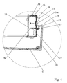
- the latching device for fixing the bezel frame 20 is described in detail with the enlarged partial sections FIGS. 4 to 6 illustrated and explained.
- This locking device consists of attached to an end face of the light chassis 10 locking levers 11, on the latching lugs 12 of the aperture frame 20 with a top web 23 arranged and downwardly directed edge lip 24 rests.
- consisting of elastic plastic locking lever 11 is fixed to the chassis 10 with a support arm 14. Its upper free end protrudes slightly with an actuating button 13 from the top of the light chassis 10 out.
- the locking lever can be deflected in the direction of the arrow A against the chassis 10, so that its locking lug 12 comes out of engagement with the edge lip 24 of the aperture frame 20.
- the bezel frame 20, at the lower webs with the interposition of a seal 22, the transparent panel 21 is mounted are pivoted downwards.
- locking lever 16 are provided on the projecting towards the bezel frame 20 locking lugs 17 of the bezel frame 20 with its edge lip 24th rests.
- These locking webs 16 are made of elastically resilient plastic and are fixed at their upper ends with retaining arms 18 on the light chassis 10, while their lower ends 16 are so pivoted upon depression of the locking lever in the direction of arrow B that their locking lugs 17 with the edge lip 24 of Aperture frame 20 disengaged.
- this is equipped with a guide arm 19, which is guided in a guide slot 19 a of the light chassis 10.
- the locking lever 11 are equipped in a corresponding manner with guide arms 15.
- the locking lug 17 of the locking lever 16 is provided with a serving as a finger receiving recess 16a.
- the panel frame 20 can be swung all the way down and, as related to FIG. 2 already mentioned, removed and z. B. against a differently trained, in FIG. 6 shown aperture frame 20 'are exchanged.
Description
Die Erfindung betrifft eine Leuchte mit einem Leuchtenchassis, welches Leuchtstofflampen trägt und an dessen Lichtaustrittsseite mittels eines lös- und verrastbaren Blendenrahmens eine transparente Blende angebracht ist.The invention relates to a lamp with a light chassis, which carries fluorescent lamps and at the light exit side by means of a detachable and latchable bezel frame, a transparent panel is attached.
Ein derart ausgebildeter Leuchtenkopf kann Teil einer Stehleuchte, aber auch Decken-, Wand- oder Tischleuchte sein.Such a trained lamp head can be part of a floor lamp, but also ceiling, wall or table lamp.
Das Design eines derartigen Leuchtenkopfes ist vor allem durch die Gestaltung der außen liegenden Teile des Leuchtenchassis und des Blendenrahmens geprägt.The design of such a lamp head is mainly characterized by the design of the outer parts of the lamp chassis and the bezel frame.
Um den unterschiedlichen Wünschen der Käufer gerecht zu werden, muss der Hersteller aus Designgründen eine Vielzahl von Leuchten unterschiedlichen Designs herstellen und auf Lager halten.In order to meet the different wishes of the buyers, the manufacturer must design and maintain a large number of luminaires of different designs in stock.
Mit der vorliegenden Erfindung soll die Herstellung der verschiedenen Ausführungsformen von Leuchten vereinfacht und damit verbilligt werden.With the present invention, the production of the various embodiments of lights to be simplified and thus cheapened.
Grundsätzlich geht die Erfindung von einer aus
Eine Änderung des Designs erfordert eine Neugestaltung des Blendenrahmens und des Chassis.Changing the design requires a redesign of the bezel frame and chassis.
Nach der vorliegenden Erfindung, nach welcher der Blendenrahmen das Leuchtenchassis umgibt und an diesem mit Hilfe einer Rasteinrichtung lösbar befestigt ist, braucht im Falle der Design-Änderung lediglich der Blendenrahmen ausgetauscht zu werden. Dieser ist am Leuchtenchassis mit auslenkbar angeordneten Rasthebeln, welche den Blendenrahmen mittels Rastnasen untergreifen und in seiner Gebrauchslage festlegen, schnell und ohne Werkzeuge befestigbar.According to the present invention, according to which the bezel surrounds the luminaire chassis and is releasably secured thereto by means of a latching device, in the case of the design change, only the bezel frame needs to be replaced. This is the light chassis with deflectable locking levers, which engage under the bezel frame by means of locking lugs and set in its position of use, quickly and without tools fastened.
Aus
Die mit der Erfindung vorgeschlagenen Rasthebel können entweder schwenkbar am Leuchtenchassis gelagert sein oder nach dem Vorschlag gemäß Anspruch 9 selbst aus elastisch verformbaren Material bestehen, so dass sie fest mit dem Leuchtenchassis verbunden werden können.The locking lever proposed by the invention may either be pivotally mounted on the light chassis or consist of the proposal according to claim 9 itself of elastically deformable material, so that they can be firmly connected to the light chassis.
Zusätzlich zu den den Blendenrahmen in seiner Gebrauchslage festlegenden Rasten werden mit Anspruch 2 Zwischenrasten vorgeschlagen, welche den Blendenrahmen in einer Zwischenlage halten, so dass dieser nicht unbeabsichtigt herunterfällt und hierdurch beschädigt wird.In addition to the frame fixing in its position of use detents are proposed with
Die Zwischenrasten können zusätzlich zu den erwähnten Rastnasen am Rasthebel vorgesehen sein. Nach dem Vorschlag gemäß Anspruch 3 sind dagegen zusätzliche Rasthebel vorgesehen, an welchen diese Zwischenrasten angebracht sind. Auch diese Rasthebel sind am Leuchtenchassis verschwenkbar angeordnet.The intermediate latches may be provided in addition to the aforementioned locking lugs on the locking lever. According to the proposal of claim 3, however, additional locking lever are provided on which these intermediate latches are attached. These locking levers are pivotally mounted on the light chassis.
Derartige Rasthebel sollten gemäß Anspruch 4 zumindest an einer Seite oder gemäß Anspruch 5 an gegenüberliegenden Seiten des Leuchtenchassis vorgesehen sein.Such locking lever should be provided according to claim 4, at least on one side or according to claim 5 on opposite sides of the light chassis.
Nach dem Vorschlag gemäß Anspruch 6 dagegen ist der Blendenrahmen auf einer Seite mit Rasthebeln und auf der den Rasthebeln gegenüberliegenden Seite des Leuchtenchassis in dieses schwenkbar und lösbar eingehängt.According to the proposal of claim 6, however, the bezel frame is mounted on one side with locking levers and on the opposite side of the locking levers of the lighting chassis in this pivotally and releasably.
Zur einfachen Betätigung des Rasthebels sind diese gemäß Anspruch 7 mit von außen zugänglichen Betätigungstasten versehen.For easy operation of the locking lever these are provided according to claim 7 with externally accessible operating buttons.
Für die Einrastung des Blendenrahmens ist dieser gemäß Anspruch 8 auf der den Rasthebeln zugewandten Seite mit einer den Rastnasen der Rasthebel zugeordneten Rast in Form eines nach innen vorspringenden Steges mit einer Randlippe ausgestattet.For the latching of the bezel this is provided according to claim 8 on the latching levers side facing the locking lugs of the locking lever associated latch in the form of an inwardly projecting web with a lip edge.
In den Zeichnungen zeigen:
Figur 1- perspektivische Darstellung einer erfindungsgemäß ausgebildeten Stehleuchte,
Figur 2- perspektivische Darstellung der Stehleuchte gemäß
Figur 1 - Figur 3
- vergrößerter Teilschnitt des Leuchtenkopfes bei eingerastetem Blendenrahmen im Bereich des Rasthebels 11,
- Figur 4
- Teilschnitt gemäß
Figur 3 im Bereich desRasthebels 16 bei gelöstem Blendenrahmen, - Figur 5
- Teilschnitt gemäß
Figur 4 bei abgeklapptem Blendenrahmen und - Figur 6
- Teilschnitt entsprechend
Figur 3 mit variiertem Blendenrahmen.
- FIG. 1
- perspective view of an inventively designed floor lamp,
- FIG. 2
- perspective view of the floor lamp according to
FIG. 1 with folding frame, - FIG. 3
- enlarged partial section of the lamp head when the frame is engaged in the region of the
locking lever 11, - FIG. 4
- Partial section according to
FIG. 3 in the region of thelocking lever 16 with dissolved frame, - FIG. 5
- Partial section according to
FIG. 4 with folded frame and - FIG. 6
- Partial section accordingly
FIG. 3 with varied aperture frame.
Die erfindungsgemäße Lösung wird anhand der in den
Der Leuchtenkopf 1 besteht im Wesentlichen aus einem Leuchtenchassis 10, an welchem mittels Lampensockeln 34 Leuchtstofflampen 33 angebracht sind. Mit einem auf halber Höhe der Ständersäule 30 angebrachten Schalter 31 können die Leuchtstofflampen 33 geschaltet werden.The
Das Leuchtenchassis 10 ist von einem Blendenrahmen 20 umgeben, welcher, wie die nachfolgenden Figuren zeigen, eine die Unterseite des Leuchtenkopfes 1 abdeckende transparente Blende 21 trägt.The
Der Blendenrahmen 20 kann nach Lösen von den Rahmen haltenden Rasthebeln 11 in die in
Die Rasteinrichtung zur Festlegung des Blendenrahmens 20 ist im Einzelnen mit den vergrößerten Teilschnitten gemäß
Diese Rasteinrichtung besteht aus an einer Stirnseite des Leuchtenchassis 10 angebrachten Rasthebeln 11, auf deren Rastnasen 12 der Blendenrahmen 20 mit einer am oberen Steg 23 angeordneten und nach unten gerichteten Randlippe 24 aufliegt. Bei dem hier dargestellten Ausführungsbeispiel ist der aus elastischem Kunststoff bestehende Rasthebel 11 mit einem Haltearm 14 am Chassis 10 befestigt. Sein oberes freies Ende ragt mit einer Betätigungstaste 13 geringfügig aus der Oberseite des Leuchtenchassis 10 heraus. Mittels dieser Betätigungstaste 13 kann der Rasthebel in Richtung des Pfeiles A gegen das Chassis 10 ausgelenkt werden, so dass seine Rastnase 12 mit der Randlippe 24 des Blendenrahmens 20 außer Eingriff kommt. Damit kann der Blendenrahmen 20, an dessen unteren Stegen unter Zwischenlage einer Dichtung 22 die transparente Blende 21 angebracht ist, nach unten weggeschwenkt werden.This locking device consists of attached to an end face of the
Um zur Erleichterung des Austausches den Blendenrahmen 20 mit der Blende 21 in einer Zwischenposition zu halten, sind seitlich versetzt zu den Rasthebeln 11 am Leuchtenchassis weitere Rasthebel 16 vorgesehen, auf deren in Richtung auf den Blendenrahmen 20 vorspringenden Rastnasen 17 der Blendenrahmen 20 mit seiner Randlippe 24 aufliegt. Auch diese Raststege 16 bestehen aus elastisch federndem Kunststoff und sind an ihren oberen Enden mit Haltearmen 18 am Leuchtenchassis 10 festgelegt, während ihre unteren Enden bei Eindrücken des Rasthebels 16 in Richtung des Pfeiles B derart verschwenkbar sind, dass ihre Rastnasen 17 mit der Randlippe 24 des Blendenrahmens 20 außer Eingriff kommen.In order to facilitate the replacement of the
Zur Lagesicherung des Rasthebels 16 ist dieser mit einem Führungsarm 19 ausgestattet, welcher in einem Führungsschlitz 19a des Leuchtenchassis 10 geführt wird.To secure the position of the
Auch die Rasthebel 11 sind in entsprechender Weise mit Führungsarmen 15 ausgestattet.The
Oberhalb der Rastnase 17 ist der Rasthebel 16 mit einer als Fingeraufnahme dienenden Vertiefung 16a versehen.Above the
Nach Eindrücken des Rasthebels 16 in Richtung des Pfeiles B kann der Blendenrahmen 20 ganz nach unten weggeschwenkt und, wie im Zusammenhang mit
- 11
- Leuchtenkopflamp head
- 1010
- Leuchtenchassisluminaire body
- 1111
- Rasthebellocking lever
- 1212
- Rastnaselocking lug
- 1313
- Betätigungstasteactuating button
- 1414
- Haltearmholding arm
- 1515
- Führungsarmguide
- 1616
- Rasthebellocking lever
- 16a16a
- Vertiefungdeepening
- 1717
- Rastnase, ZwischenrasteLatch, intermediate catch
- 1818
- Haltearmholding arm
- 1919
- Führungsarmguide
- 19a19a
- Führungsschlitzguide slot
- 2020
- Blendenrahmenpanel frame
- 20'20 '
- Blendenrahmenpanel frame
- 2121
- Blendecover
- 2222
- Dichtungpoetry
- 2323
- oberer Stegupper jetty
- 2424
- Randlippeperipheral lip
- 2525
- unterer Steglower jetty
- 2626
- Aufnahmenutreceiving groove
- 3030
- Ständersäuleupright column
- 3131
- Schalterswitch
- 3232
- Fußfoot
- 3333
- Leuchtstofflampenfluorescent lamps
- 3434
- Lampensockellamp base
Claims (9)
- A light fixture with a light fixture frame (10) which carries fluorescent lamps (33), and a transparent screen (21) is attached to the light emission side of the aforesaid light fixture frame (10) by means of a releasable and engageable screen frame (20, 20'), characterized in that the screen frame (20, 20') surrounds the light fixture frame (10) and is fastened to the latter in an interchangeable manner by means of catch levers (11) which are arranged on the light fixture frame (10) in a deflectable manner and which engage under the screen frame (20, 20') by means of catch projections (12) and fix it in its position of use.
- A light fixture according to claim 1, characterized in that, in addition to the catch projections (12) holding the screen frame (20, 20') in its position of use, intermediate catches (17) are provided which hold the screen frame (20, 20') in an intermediate position.
- A light fixture according to claim 2, characterized in that the intermediate catches are provided in the form of catch projections (17) on additional catch levers (16) which are arranged in a pivotable manner on the light fixture frame (10).
- A light fixture according to claim 1, 2 or 3, characterized in that the catch levers (11, 16) are arranged at least on one side of the light fixture frame (10).
- A light fixture according to claim 1, 2 or 3, characterized in that the catch levers (11, 16) are arranged on opposite sides of the light fixture frame (10).
- A light fixture according to claim 4, characterized in that the screen frame (20, 20') is suspended on the side of the light fixture frame (10) opposite the catch levers (11, 16) so as to be releasable and pivotable into the light fixture frame (10).
- A light fixture according to any one of claims 1 to 6, characterized in that the catch levers (11) have actuation buttons (13) accessible from the outside.
- A light fixture according to any one of claims 1 to 7, characterized in that at least on the side facing the catch levers (11, 16) the screen frame (20, 20') has a catch - associated with the catch projections (12, 17) of the catch levers (11, 16) - in the form of an inwardly projecting web (23) with an edge lip (24).
- A light fixture according to any one of the preceding claims, characterized in that the catch levers (11, 16) consist of resiliently deformable material and are connected at one end (14, 18) thereof to the light fixture frame (10) in a fixed manner, whereas the catch projections (12, 17) are provided at the free end.
Applications Claiming Priority (2)
| Application Number | Priority Date | Filing Date | Title |
|---|---|---|---|
| DE202008014799U DE202008014799U1 (en) | 2008-11-07 | 2008-11-07 | lamp |
| PCT/EP2009/006419 WO2010051875A1 (en) | 2008-11-07 | 2009-09-04 | Luminaire |
Publications (2)
| Publication Number | Publication Date |
|---|---|
| EP2342492A1 EP2342492A1 (en) | 2011-07-13 |
| EP2342492B1 true EP2342492B1 (en) | 2014-03-12 |
Family
ID=40279811
Family Applications (1)
| Application Number | Title | Priority Date | Filing Date |
|---|---|---|---|
| EP09778333.6A Not-in-force EP2342492B1 (en) | 2008-11-07 | 2009-09-04 | Luminaire |
Country Status (5)
| Country | Link |
|---|---|
| US (1) | US20110199761A1 (en) |
| EP (1) | EP2342492B1 (en) |
| CN (1) | CN102177396A (en) |
| DE (1) | DE202008014799U1 (en) |
| WO (1) | WO2010051875A1 (en) |
Families Citing this family (2)
| Publication number | Priority date | Publication date | Assignee | Title |
|---|---|---|---|---|
| CN105222031A (en) * | 2015-09-22 | 2016-01-06 | 江苏健享实业有限公司 | A kind of street lamp just overhauled |
| WO2023021015A1 (en) | 2021-08-19 | 2023-02-23 | Signify Holding B.V. | Luminaire latch |
Family Cites Families (7)
| Publication number | Priority date | Publication date | Assignee | Title |
|---|---|---|---|---|
| US2997321A (en) * | 1960-02-01 | 1961-08-22 | Sunbeam Lighting Company | Touch latch for ceiling light fixtures |
| US5172976A (en) * | 1991-09-27 | 1992-12-22 | Cooper Industries, Inc. | Light fixture latch and latch hinge assemblies |
| FR2695983B1 (en) * | 1992-09-22 | 1994-11-25 | Sarlam | Waterproof light porthole, with easy closing. |
| USD417301S (en) * | 1998-09-30 | 1999-11-30 | Hein William A | Light fixture |
| US7585088B2 (en) * | 2007-04-03 | 2009-09-08 | Abl Ip Holding Llc | Fluorescent lamp fixture |
| US20090244908A1 (en) * | 2008-04-01 | 2009-10-01 | Stephen Haight Lydecker | Louver for Light Assembly |
| US8038318B2 (en) * | 2008-05-06 | 2011-10-18 | Koninklijke Philips Electronics N.V. | Door frame mounted reflector system for fluorescent troffer |
-
2008
- 2008-11-07 DE DE202008014799U patent/DE202008014799U1/en not_active Expired - Lifetime
-
2009
- 2009-09-04 WO PCT/EP2009/006419 patent/WO2010051875A1/en active Application Filing
- 2009-09-04 US US13/059,628 patent/US20110199761A1/en not_active Abandoned
- 2009-09-04 CN CN2009801401622A patent/CN102177396A/en active Pending
- 2009-09-04 EP EP09778333.6A patent/EP2342492B1/en not_active Not-in-force
Also Published As
| Publication number | Publication date |
|---|---|
| US20110199761A1 (en) | 2011-08-18 |
| CN102177396A (en) | 2011-09-07 |
| WO2010051875A1 (en) | 2010-05-14 |
| DE202008014799U1 (en) | 2009-01-15 |
| EP2342492A1 (en) | 2011-07-13 |
Similar Documents
| Publication | Publication Date | Title |
|---|---|---|
| DE102007010023A1 (en) | Motor vehicle headlamp e.g. side flash light, has optical fiber arrangement with fasteners that connects arrangement directly with housing, such that arrangement extends between fasteners in self supporting manner | |
| DE202006003392U1 (en) | Motor vehicle headlamp e.g. side flash light, has optical fiber arrangement with fasteners that connects arrangement directly with housing, such that arrangement extends between fasteners in self supporting manner | |
| DE2314416B2 (en) | Fastening device | |
| EP2342492B1 (en) | Luminaire | |
| WO2006027150A1 (en) | Radiator | |
| EP2976969A1 (en) | Combination of a table and a luminaire | |
| DE202007009232U1 (en) | Diffuser for releasably attaching to a reflector screen or the like. | |
| DE202017103159U1 (en) | convection tub | |
| DE2943544C2 (en) | Attachment of a translucent pane | |
| EP2994693A1 (en) | Cover element for flat luminaire | |
| WO2010023047A1 (en) | Drawer | |
| DE202010004780U1 (en) | Luminaire with elongated housing | |
| AT10609U1 (en) | FURNITURE WITH DRAWER | |
| DE202011051616U1 (en) | An LED interior light | |
| EP2208192B1 (en) | Pictogram lamp | |
| DE202018105176U1 (en) | Roof box with lighting device | |
| DE10035528B4 (en) | Light, especially reading light for vehicles | |
| DE202007013177U1 (en) | lamp | |
| EP3395290A1 (en) | Dental light curing apparatus | |
| DE102007054664A1 (en) | Information carrier e.g. name plate, has front wall provided with transparent symbols, and light scattering pane, which is arranged at region of rear side of front wall and is illuminated by light source i.e. LED | |
| DE202012101963U1 (en) | vehicle lamp | |
| DE202011050288U1 (en) | House canopy with LED lighting | |
| DE102023124358A1 (en) | lamp | |
| DE1764421C (en) | Fluorescent tube lamp holder | |
| DE202014103273U1 (en) | Ratchet wrench with a multi-angle mounting structure |
Legal Events
| Date | Code | Title | Description |
|---|---|---|---|
| PUAI | Public reference made under article 153(3) epc to a published international application that has entered the european phase |
Free format text: ORIGINAL CODE: 0009012 |
|
| 17P | Request for examination filed |
Effective date: 20110210 |
|
| AK | Designated contracting states |
Kind code of ref document: A1 Designated state(s): AT BE BG CH CY CZ DE DK EE ES FI FR GB GR HR HU IE IS IT LI LT LU LV MC MK MT NL NO PL PT RO SE SI SK SM TR |
|
| AX | Request for extension of the european patent |
Extension state: AL BA RS |
|
| DAX | Request for extension of the european patent (deleted) | ||
| GRAP | Despatch of communication of intention to grant a patent |
Free format text: ORIGINAL CODE: EPIDOSNIGR1 |
|
| INTG | Intention to grant announced |
Effective date: 20131030 |
|
| GRAS | Grant fee paid |
Free format text: ORIGINAL CODE: EPIDOSNIGR3 |
|
| GRAA | (expected) grant |
Free format text: ORIGINAL CODE: 0009210 |
|
| AK | Designated contracting states |
Kind code of ref document: B1 Designated state(s): AT BE BG CH CY CZ DE DK EE ES FI FR GB GR HR HU IE IS IT LI LT LU LV MC MK MT NL NO PL PT RO SE SI SK SM TR |
|
| REG | Reference to a national code |
Ref country code: GB Ref legal event code: FG4D Free format text: NOT ENGLISH |
|
| REG | Reference to a national code |
Ref country code: CH Ref legal event code: EP |
|
| REG | Reference to a national code |
Ref country code: AT Ref legal event code: REF Ref document number: 656547 Country of ref document: AT Kind code of ref document: T Effective date: 20140315 |
|
| REG | Reference to a national code |
Ref country code: CH Ref legal event code: NV Representative=s name: R. A. EGLI AND CO. PATENTANWAELTE, CH |
|
| REG | Reference to a national code |
Ref country code: IE Ref legal event code: FG4D Free format text: LANGUAGE OF EP DOCUMENT: GERMAN |
|
| REG | Reference to a national code |
Ref country code: DE Ref legal event code: R096 Ref document number: 502009008994 Country of ref document: DE Effective date: 20140424 |
|
| REG | Reference to a national code |
Ref country code: SE Ref legal event code: TRGR |
|
| REG | Reference to a national code |
Ref country code: NL Ref legal event code: T3 |
|
| PG25 | Lapsed in a contracting state [announced via postgrant information from national office to epo] |
Ref country code: LT Free format text: LAPSE BECAUSE OF FAILURE TO SUBMIT A TRANSLATION OF THE DESCRIPTION OR TO PAY THE FEE WITHIN THE PRESCRIBED TIME-LIMIT Effective date: 20140312 Ref country code: NO Free format text: LAPSE BECAUSE OF FAILURE TO SUBMIT A TRANSLATION OF THE DESCRIPTION OR TO PAY THE FEE WITHIN THE PRESCRIBED TIME-LIMIT Effective date: 20140612 |
|
| REG | Reference to a national code |
Ref country code: LT Ref legal event code: MG4D |
|
| PG25 | Lapsed in a contracting state [announced via postgrant information from national office to epo] |
Ref country code: FI Free format text: LAPSE BECAUSE OF FAILURE TO SUBMIT A TRANSLATION OF THE DESCRIPTION OR TO PAY THE FEE WITHIN THE PRESCRIBED TIME-LIMIT Effective date: 20140312 Ref country code: CY Free format text: LAPSE BECAUSE OF FAILURE TO SUBMIT A TRANSLATION OF THE DESCRIPTION OR TO PAY THE FEE WITHIN THE PRESCRIBED TIME-LIMIT Effective date: 20140312 |
|
| PG25 | Lapsed in a contracting state [announced via postgrant information from national office to epo] |
Ref country code: LV Free format text: LAPSE BECAUSE OF FAILURE TO SUBMIT A TRANSLATION OF THE DESCRIPTION OR TO PAY THE FEE WITHIN THE PRESCRIBED TIME-LIMIT Effective date: 20140312 Ref country code: HR Free format text: LAPSE BECAUSE OF FAILURE TO SUBMIT A TRANSLATION OF THE DESCRIPTION OR TO PAY THE FEE WITHIN THE PRESCRIBED TIME-LIMIT Effective date: 20140312 |
|
| PG25 | Lapsed in a contracting state [announced via postgrant information from national office to epo] |
Ref country code: CZ Free format text: LAPSE BECAUSE OF FAILURE TO SUBMIT A TRANSLATION OF THE DESCRIPTION OR TO PAY THE FEE WITHIN THE PRESCRIBED TIME-LIMIT Effective date: 20140312 Ref country code: IS Free format text: LAPSE BECAUSE OF FAILURE TO SUBMIT A TRANSLATION OF THE DESCRIPTION OR TO PAY THE FEE WITHIN THE PRESCRIBED TIME-LIMIT Effective date: 20140712 Ref country code: EE Free format text: LAPSE BECAUSE OF FAILURE TO SUBMIT A TRANSLATION OF THE DESCRIPTION OR TO PAY THE FEE WITHIN THE PRESCRIBED TIME-LIMIT Effective date: 20140312 Ref country code: BG Free format text: LAPSE BECAUSE OF FAILURE TO SUBMIT A TRANSLATION OF THE DESCRIPTION OR TO PAY THE FEE WITHIN THE PRESCRIBED TIME-LIMIT Effective date: 20140612 Ref country code: RO Free format text: LAPSE BECAUSE OF FAILURE TO SUBMIT A TRANSLATION OF THE DESCRIPTION OR TO PAY THE FEE WITHIN THE PRESCRIBED TIME-LIMIT Effective date: 20140312 |
|
| PG25 | Lapsed in a contracting state [announced via postgrant information from national office to epo] |
Ref country code: SK Free format text: LAPSE BECAUSE OF FAILURE TO SUBMIT A TRANSLATION OF THE DESCRIPTION OR TO PAY THE FEE WITHIN THE PRESCRIBED TIME-LIMIT Effective date: 20140312 Ref country code: PL Free format text: LAPSE BECAUSE OF FAILURE TO SUBMIT A TRANSLATION OF THE DESCRIPTION OR TO PAY THE FEE WITHIN THE PRESCRIBED TIME-LIMIT Effective date: 20140312 Ref country code: ES Free format text: LAPSE BECAUSE OF FAILURE TO SUBMIT A TRANSLATION OF THE DESCRIPTION OR TO PAY THE FEE WITHIN THE PRESCRIBED TIME-LIMIT Effective date: 20140312 |
|
| REG | Reference to a national code |
Ref country code: DE Ref legal event code: R097 Ref document number: 502009008994 Country of ref document: DE |
|
| PG25 | Lapsed in a contracting state [announced via postgrant information from national office to epo] |
Ref country code: PT Free format text: LAPSE BECAUSE OF FAILURE TO SUBMIT A TRANSLATION OF THE DESCRIPTION OR TO PAY THE FEE WITHIN THE PRESCRIBED TIME-LIMIT Effective date: 20140714 |
|
| PLBE | No opposition filed within time limit |
Free format text: ORIGINAL CODE: 0009261 |
|
| STAA | Information on the status of an ep patent application or granted ep patent |
Free format text: STATUS: NO OPPOSITION FILED WITHIN TIME LIMIT |
|
| PG25 | Lapsed in a contracting state [announced via postgrant information from national office to epo] |
Ref country code: DK Free format text: LAPSE BECAUSE OF FAILURE TO SUBMIT A TRANSLATION OF THE DESCRIPTION OR TO PAY THE FEE WITHIN THE PRESCRIBED TIME-LIMIT Effective date: 20140312 |
|
| 26N | No opposition filed |
Effective date: 20141215 |
|
| REG | Reference to a national code |
Ref country code: DE Ref legal event code: R097 Ref document number: 502009008994 Country of ref document: DE Effective date: 20141215 |
|
| PG25 | Lapsed in a contracting state [announced via postgrant information from national office to epo] |
Ref country code: MC Free format text: LAPSE BECAUSE OF FAILURE TO SUBMIT A TRANSLATION OF THE DESCRIPTION OR TO PAY THE FEE WITHIN THE PRESCRIBED TIME-LIMIT Effective date: 20140312 |
|
| REG | Reference to a national code |
Ref country code: IE Ref legal event code: MM4A |
|
| PG25 | Lapsed in a contracting state [announced via postgrant information from national office to epo] |
Ref country code: SI Free format text: LAPSE BECAUSE OF FAILURE TO SUBMIT A TRANSLATION OF THE DESCRIPTION OR TO PAY THE FEE WITHIN THE PRESCRIBED TIME-LIMIT Effective date: 20140312 |
|
| PG25 | Lapsed in a contracting state [announced via postgrant information from national office to epo] |
Ref country code: IE Free format text: LAPSE BECAUSE OF NON-PAYMENT OF DUE FEES Effective date: 20140904 |
|
| PG25 | Lapsed in a contracting state [announced via postgrant information from national office to epo] |
Ref country code: SM Free format text: LAPSE BECAUSE OF FAILURE TO SUBMIT A TRANSLATION OF THE DESCRIPTION OR TO PAY THE FEE WITHIN THE PRESCRIBED TIME-LIMIT Effective date: 20140312 |
|
| PG25 | Lapsed in a contracting state [announced via postgrant information from national office to epo] |
Ref country code: GR Free format text: LAPSE BECAUSE OF FAILURE TO SUBMIT A TRANSLATION OF THE DESCRIPTION OR TO PAY THE FEE WITHIN THE PRESCRIBED TIME-LIMIT Effective date: 20140613 Ref country code: MT Free format text: LAPSE BECAUSE OF FAILURE TO SUBMIT A TRANSLATION OF THE DESCRIPTION OR TO PAY THE FEE WITHIN THE PRESCRIBED TIME-LIMIT Effective date: 20140312 |
|
| PG25 | Lapsed in a contracting state [announced via postgrant information from national office to epo] |
Ref country code: HU Free format text: LAPSE BECAUSE OF FAILURE TO SUBMIT A TRANSLATION OF THE DESCRIPTION OR TO PAY THE FEE WITHIN THE PRESCRIBED TIME-LIMIT; INVALID AB INITIO Effective date: 20090904 Ref country code: TR Free format text: LAPSE BECAUSE OF FAILURE TO SUBMIT A TRANSLATION OF THE DESCRIPTION OR TO PAY THE FEE WITHIN THE PRESCRIBED TIME-LIMIT Effective date: 20140312 |
|
| REG | Reference to a national code |
Ref country code: FR Ref legal event code: PLFP Year of fee payment: 8 |
|
| REG | Reference to a national code |
Ref country code: FR Ref legal event code: PLFP Year of fee payment: 9 |
|
| PG25 | Lapsed in a contracting state [announced via postgrant information from national office to epo] |
Ref country code: MK Free format text: LAPSE BECAUSE OF FAILURE TO SUBMIT A TRANSLATION OF THE DESCRIPTION OR TO PAY THE FEE WITHIN THE PRESCRIBED TIME-LIMIT Effective date: 20140312 |
|
| REG | Reference to a national code |
Ref country code: FR Ref legal event code: PLFP Year of fee payment: 10 |
|
| PGFP | Annual fee paid to national office [announced via postgrant information from national office to epo] |
Ref country code: LU Payment date: 20190923 Year of fee payment: 11 Ref country code: IT Payment date: 20190920 Year of fee payment: 11 Ref country code: SE Payment date: 20190924 Year of fee payment: 11 Ref country code: FR Payment date: 20190923 Year of fee payment: 11 Ref country code: NL Payment date: 20190923 Year of fee payment: 11 |
|
| PGFP | Annual fee paid to national office [announced via postgrant information from national office to epo] |
Ref country code: AT Payment date: 20190918 Year of fee payment: 11 Ref country code: GB Payment date: 20190924 Year of fee payment: 11 |
|
| PGFP | Annual fee paid to national office [announced via postgrant information from national office to epo] |
Ref country code: DE Payment date: 20191029 Year of fee payment: 11 Ref country code: CH Payment date: 20190924 Year of fee payment: 11 |
|
| PGFP | Annual fee paid to national office [announced via postgrant information from national office to epo] |
Ref country code: BE Payment date: 20190923 Year of fee payment: 11 |
|
| REG | Reference to a national code |
Ref country code: DE Ref legal event code: R119 Ref document number: 502009008994 Country of ref document: DE |
|
| REG | Reference to a national code |
Ref country code: CH Ref legal event code: PL |
|
| REG | Reference to a national code |
Ref country code: NL Ref legal event code: MM Effective date: 20201001 |
|
| REG | Reference to a national code |
Ref country code: AT Ref legal event code: MM01 Ref document number: 656547 Country of ref document: AT Kind code of ref document: T Effective date: 20200904 |
|
| GBPC | Gb: european patent ceased through non-payment of renewal fee |
Effective date: 20200904 |
|
| REG | Reference to a national code |
Ref country code: BE Ref legal event code: MM Effective date: 20200930 |
|
| PG25 | Lapsed in a contracting state [announced via postgrant information from national office to epo] |
Ref country code: NL Free format text: LAPSE BECAUSE OF NON-PAYMENT OF DUE FEES Effective date: 20201001 Ref country code: LU Free format text: LAPSE BECAUSE OF NON-PAYMENT OF DUE FEES Effective date: 20200904 |
|
| PG25 | Lapsed in a contracting state [announced via postgrant information from national office to epo] |
Ref country code: DE Free format text: LAPSE BECAUSE OF NON-PAYMENT OF DUE FEES Effective date: 20210401 Ref country code: FR Free format text: LAPSE BECAUSE OF NON-PAYMENT OF DUE FEES Effective date: 20200930 |
|
| PG25 | Lapsed in a contracting state [announced via postgrant information from national office to epo] |
Ref country code: BE Free format text: LAPSE BECAUSE OF NON-PAYMENT OF DUE FEES Effective date: 20200930 Ref country code: AT Free format text: LAPSE BECAUSE OF NON-PAYMENT OF DUE FEES Effective date: 20200904 Ref country code: CH Free format text: LAPSE BECAUSE OF NON-PAYMENT OF DUE FEES Effective date: 20200930 Ref country code: SE Free format text: LAPSE BECAUSE OF NON-PAYMENT OF DUE FEES Effective date: 20200905 Ref country code: LI Free format text: LAPSE BECAUSE OF NON-PAYMENT OF DUE FEES Effective date: 20200930 Ref country code: GB Free format text: LAPSE BECAUSE OF NON-PAYMENT OF DUE FEES Effective date: 20200904 |
|
| REG | Reference to a national code |
Ref country code: SE Ref legal event code: EUG |
|
| PG25 | Lapsed in a contracting state [announced via postgrant information from national office to epo] |
Ref country code: IT Free format text: LAPSE BECAUSE OF NON-PAYMENT OF DUE FEES Effective date: 20200904 |